EP2369197A1 - Double actuation system for truck clutch - Google Patents
Double actuation system for truck clutch Download PDFInfo
- Publication number
- EP2369197A1 EP2369197A1 EP10425068A EP10425068A EP2369197A1 EP 2369197 A1 EP2369197 A1 EP 2369197A1 EP 10425068 A EP10425068 A EP 10425068A EP 10425068 A EP10425068 A EP 10425068A EP 2369197 A1 EP2369197 A1 EP 2369197A1
- Authority
- EP
- European Patent Office
- Prior art keywords
- assistance
- pneumatic
- servo
- actuation system
- master
- Prior art date
- Legal status (The legal status is an assumption and is not a legal conclusion. Google has not performed a legal analysis and makes no representation as to the accuracy of the status listed.)
- Granted
Links
Images




Classifications
-
- F—MECHANICAL ENGINEERING; LIGHTING; HEATING; WEAPONS; BLASTING
- F16—ENGINEERING ELEMENTS AND UNITS; GENERAL MEASURES FOR PRODUCING AND MAINTAINING EFFECTIVE FUNCTIONING OF MACHINES OR INSTALLATIONS; THERMAL INSULATION IN GENERAL
- F16D—COUPLINGS FOR TRANSMITTING ROTATION; CLUTCHES; BRAKES
- F16D48/00—External control of clutches
- F16D48/02—Control by fluid pressure
- F16D48/04—Control by fluid pressure providing power assistance
-
- F—MECHANICAL ENGINEERING; LIGHTING; HEATING; WEAPONS; BLASTING
- F16—ENGINEERING ELEMENTS AND UNITS; GENERAL MEASURES FOR PRODUCING AND MAINTAINING EFFECTIVE FUNCTIONING OF MACHINES OR INSTALLATIONS; THERMAL INSULATION IN GENERAL
- F16D—COUPLINGS FOR TRANSMITTING ROTATION; CLUTCHES; BRAKES
- F16D48/00—External control of clutches
- F16D48/02—Control by fluid pressure
- F16D2048/0215—Control by fluid pressure for damping of pulsations within the fluid system
-
- F—MECHANICAL ENGINEERING; LIGHTING; HEATING; WEAPONS; BLASTING
- F16—ENGINEERING ELEMENTS AND UNITS; GENERAL MEASURES FOR PRODUCING AND MAINTAINING EFFECTIVE FUNCTIONING OF MACHINES OR INSTALLATIONS; THERMAL INSULATION IN GENERAL
- F16D—COUPLINGS FOR TRANSMITTING ROTATION; CLUTCHES; BRAKES
- F16D48/00—External control of clutches
- F16D48/02—Control by fluid pressure
- F16D2048/0227—Source of pressure producing the clutch engagement or disengagement action within a circuit; Means for initiating command action in power assisted devices
- F16D2048/0254—Double actuation, i.e. two actuation means can produce independently an engagement or disengagement of the clutch
Definitions
- This invention relates to a clutch actuation system, in particular a clutch actuation system having a double pneumatic component assistance, which confers low clutch pedal effort for use in trucks, mainly median/heavy trucks.
- pneumatic devices were employed to facilitate the actuation in automotive vehicles. These devices provided different ways to aid the user's effort with a servo-assisted system.
- the standard actuation system for median/heavy truck used in the prior art systems comprises a master cylinder, including a single hydraulic system, and a servo-assisted system, having a hydraulic system and pneumatic component assistance.
- the model STRALIS currently available by IVECO uses a clutch actuation system with a master cylinder and a servo assistance. With this configuration, the pedal effort is around 16 kg causing high clutch pedal effort.
- the purpose of the present invention is to provide a comparatively simple and inexpensive double actuation system comprising:
- a double actuation system comprising a master assistance (hydraulic system + pneumatic component assistance) and servo-assistance (hydraulic system + pneumatic component assistance).
- a master assistance hydraulic system + pneumatic component assistance
- servo-assistance hydraulic system + pneumatic component assistance
- the present invention also relates to a new hydraulic pipe with a pressure regulator valve and a muffler, which are specially adapted to prevent clutch pedal trepidation.
- this prior art system uses a standard actuation system comprising a master cylinder (hydraulic system) and a servo assistance (hydraulic system + pneumatic component assistance), which provides a high pedal effort.
- a master cylinder hydraulic system
- a servo assistance hydraulic system + pneumatic component assistance
- FIG. 2 represents a graph of clutch pedal effort according to present invention, using a double actuation system comprising:
- This new configuration provides a reduced pedal effort to approximately 8.5 Kg (having a pedal travel of 140 mm).
- An important feature provided by the configuration of the present invention is that this reduced clutch pedal effort is obtained without increasing the size of pedal.
- the operation of the hydraulic system (H) of the clutch double actuation system occurs as follow: the clutch pedal (1) triggers the master cylinder (2.3), generating the shift of the oil supplied by reservoir (2.1) moving the piston of the servo cylinder (4.1). The rod of the servo cylinder moves the clutch fork (5). Then, the displacement of the bearing (6) occurs and disengages the clutch disc, causing the disconnection of the engine flywheel (8) of transmission (7), allowing smooth engagement of the gear, as shown in Figure 3A .
- the hydraulic pressure is around of 6, 5 bar.
- the operation of the pneumatic component assistance occurs as follows: the beginning of the actuation of pedal opens the feeding to the pneumatic cylinder (2.2) of the master valve (2), reducing the effort to move the hydraulic fluid that also is made by the pneumatic component assistance.
- a similar process occurs in the servo valve (4), the beginning of the actuation generates an increase in hydraulic pressure due to the resistance to uncoupling of the clutch disc, which releases the feeding to the cylinder (4.2).
- the pressure pneumatic system reaches each pneumatic cylinder in a range between 7.0 Bar and 11.0 Bar. In a preferred embodiment, said range is between 8.0 Bar and 9.0 Bar. More preferably, said pressure is reduced to around 8.5 Bar.
- the pneumatic component assistance (P) is disposed according to the following arrangement: atmospheric air enters into the compressor (9), which pressurizes the same. The air passes through a pneumatic manager element (10) and is stored in the reservoir (11).
- the actuation system of the present invention counts on a pneumatic pressure regulator valve (12) and a muffler (13) to equalize the effort and the sensibility in the clutch pedal.
- the present invention includes a muffler (13), which is a component that reduces backpressure by means of a resonating chamber, which is specifically tuned to cause destructive interference in the fluid, where opposite waves cancel each other out for reducing the speed of the fluid.
- the pneumatic feeding in the valve (4) reduces the hydraulic pressure by indirect reduction of the effort and the valve (2) reduces directly the drive's effort.
- the pneumatic feeding at valve (4) reduces the hydraulic pressure by indirect reduction of the effort, and the valve (2) directly reduces the effort. Therefore, the present invention provides a pneumatic pressure of approximately 8,5 bar and a hydraulic pressure of approximately 6,5 bar.
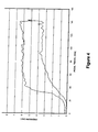
- FIG. 4 shows a graph indicating the measurement results of hydraulic pressure vs. pedal travel of the clutch actuation system according to the present invention.
- the low hydraulic pressure, around 6 bar is an evidence that de servo assistance is working.
- FIG. 5 shows a graph of clutch pedal comparison between the present invention and several models of prior of art.
- VOLVO and SCANIA have a low pedal load, but thanks to a high pedal travel.
- VW offers a very good performance, but with a low plate bearing load.
- Table 1 is a comparative table between the prior art system and the double actuation system regarding air consumption.
- TABLE 1 Prior art system Double actuation system Compressor air mass supplied 9,91 g/s 9,91 g/s Total mass that clutch actuation system demands 2,71 g/action 3,01 g/action Total air mass consumption 2,71 g/s 3,01 g/s Air consumption/air supply 27,4% 30,4%
- An additional advantage of the present invention is that the master assistance and the servo assistance of this double actuation system can operate independently. This means that if one of the assistances of the master assistance or of the servo assistance fails, the actuation system can still work, as the load for actuating the clutch pedal will be about 16 Kg, according to the preferred embodiment. This load of 16 Kg is still acceptable for a safe driving.
- the present invention offers a double actuation system for a median/heavy truck, said double actuation system having master assistance (hydraulic system + pneumatic component assistance) and a servo assistance (hydraulic system + pneumatic component assistance), which provides enhanced durability to the disc clutch and plate.
- master assistance hydraulic system + pneumatic component assistance
- servo assistance hydraulic system + pneumatic component assistance
- a pneumatic pressure regulator valve to be included in the pneumatic component assistance, which feeds the "master assistance” and the "servo assistance” in combination with a muffler (13) specially adapted to prevent clutch pedal (1) trepidation.
Landscapes
- Engineering & Computer Science (AREA)
- General Engineering & Computer Science (AREA)
- Physics & Mathematics (AREA)
- Fluid Mechanics (AREA)
- Mechanical Engineering (AREA)
- Hydraulic Clutches, Magnetic Clutches, Fluid Clutches, And Fluid Joints (AREA)
Abstract
- a "master assistance" (M) that comprises a hydraulic system and pneumatic component assistance;
- a "servo assistance" (S) that comprises a hydraulic system and pneumatic component assistance; and
- a pneumatic pressure regulator valve (12) to be included in the pneumatic component assistance which feeds the "master assistance" (M) and the "servo assistance" (S) in combination with a muffler (13) included in the hydraulic pipe (3), between said "master assistance" (M) and the "servo assistance" (S), which is particularly adapted to prevent clutch pedal trepidation.
Description
- This invention relates to a clutch actuation system, in particular a clutch actuation system having a double pneumatic component assistance, which confers low clutch pedal effort for use in trucks, mainly median/heavy trucks.
- In the past, pneumatic devices were employed to facilitate the actuation in automotive vehicles. These devices provided different ways to aid the user's effort with a servo-assisted system.
- The standard actuation system for median/heavy truck, used in the prior art systems comprises a master cylinder, including a single hydraulic system, and a servo-assisted system, having a hydraulic system and pneumatic component assistance.
- It is currently available in the market several models of heavy truck that uses clutch actuation system, such as SCANIA® R420 or VOLVO® FH 440. These systems provide a clutch actuation system with a pedal effort of at least 9.0 kg and 10.7 Kg, respectively, but to achieve said effort it is necessary to substantially increase the size and the travel of the pedal, which leads to cost increase and ergonomic problems causing discomfort to the driver. Besides, this configuration employed by Scania and Volvo causes wear of the plate and the clutch facing due to extended pedal travel.
- The model STRALIS currently available by IVECO uses a clutch actuation system with a master cylinder and a servo assistance. With this configuration, the pedal effort is around 16 kg causing high clutch pedal effort.
- Therefore, it does not exist in the prior art a clutch actuation system which provides at the same time low clutch pedal effort and low pedal trepidation.
- Against this background, the purpose of the present invention is to provide a comparatively simple and inexpensive double actuation system comprising:
- a "master assistance" that comprises a hydraulic system and pneumatic component assistance;
- a "servo assistance" that comprises a hydraulic system and pneumatic component assistance; and
- a pressure regulator valve to be included in the pneumatic component assistance, which feeds the "master assistance" and the "servo assistance" in combination with a muffler specially adapted to prevent clutch pedal trepidation.
- The above-mentioned drawbacks have been successfully solved by the present invention by means of a clutch actuation system provided with double pneumatic component assistance, which provides low clutch pedal effort and low pedal trepidation for use in median/heavy truck vehicles.
- According to a preferred embodiment of the invention, it is provided a double actuation system comprising a master assistance (hydraulic system + pneumatic component assistance) and servo-assistance (hydraulic system + pneumatic component assistance). With the configuration of the present invention, the pedal effort is reduced to approximately 8.5 Kg (having a pedal travel of 140 mm). A important feature of this arrangement is that this reduced clutch pedal effort is obtained without increasing the dimensions of pedal. By using the present configuration, the driver's comfort is enhanced. Also, if one of pneumatic component assistance fails, the system will not stop working due to the existence of another component pneumatic. Finally, said system will provide more durability to disc clutch and plate.
- The present invention also relates to a new hydraulic pipe with a pressure regulator valve and a muffler, which are specially adapted to prevent clutch pedal trepidation.
- Further areas of applicability will become apparent from the description provided herein. It should be understood that the description and specific examples are intended for purposes of illustration only and are not intended to limit the scope of the present disclosure.
- The present invention will be explained by means of a detailed description of a preferred, but non-exclusive, embodiment shown with the aid of the drawings that are attached hereto, which are merely illustrative and not-limitative, in which:
-
Figure 1 depicts a graphical representation of the load to which the driver is subject upon actuating the clutch pedal of a standard actuation system used in the prior art. -
Figure 2 shows a graphical representation of the load to which the driver is subject upon actuating the clutch pedal in accordance with the present invention. -
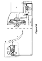
Figures 3A and3B show the operation of clutch double actuation system according to the present invention. -
Figure 4 shows a graph indicating the measurement results of hydraulic pressure x pedal travel of the clutch actuation system according to the present invention. -
Figure 5 shows a graph of clutch pedal comparison between the present invention and commercial available of actuation system the prior of art. - The following description is merely exemplary in nature and is in no way intended to limit the invention, its application, or uses.
- With reference to
Figure 1 , a graph depicting the load versus pedal travel is presented. The load to which the driver is subject upon actuating the clutch pedal of a prior art actuation system is about 16 Kg. This high load imposes an uncomfortable environment to the driver due to an excessive effort to actuate the clutch pedal, in particular for those working many hours a day. - As previously discussed, this prior art system uses a standard actuation system comprising a master cylinder (hydraulic system) and a servo assistance (hydraulic system + pneumatic component assistance), which provides a high pedal effort.
- Referring now to
Figure 2 , which represents a graph of clutch pedal effort according to present invention, using a double actuation system comprising: - a "master assistance" (M) that comprises a hydraulic system (H) and pneumatic component assistance (P);
- a "servo assistance" (S) that comprises a hydraulic system (H) and pneumatic component assistance (P); and
- a pneumatic pressure regulator valve (12) to be included in the pneumatic component assistance (P) which feeds the "master assistance" (M) and the "servo assistance" (S) in combination with a muffler (13) included in the hydraulic pipe (3), between said "master assistance" (M) and the "servo assistance" (S), which is particularly adapted to prevent clutch pedal trepidation.
- This new configuration provides a reduced pedal effort to approximately 8.5 Kg (having a pedal travel of 140 mm). An important feature provided by the configuration of the present invention is that this reduced clutch pedal effort is obtained without increasing the size of pedal.
- According to a preferred embodiment of the invention, the operation of the hydraulic system (H) of the clutch double actuation system occurs as follow: the clutch pedal (1) triggers the master cylinder (2.3), generating the shift of the oil supplied by reservoir (2.1) moving the piston of the servo cylinder (4.1). The rod of the servo cylinder moves the clutch fork (5). Then, the displacement of the bearing (6) occurs and disengages the clutch disc, causing the disconnection of the engine flywheel (8) of transmission (7), allowing smooth engagement of the gear, as shown in
Figure 3A . The hydraulic pressure is around of 6, 5 bar. - According to a preferred embodiment of the invention shown in
Figure 3A , the operation of the pneumatic component assistance (P) occurs as follows: the beginning of the actuation of pedal opens the feeding to the pneumatic cylinder (2.2) of the master valve (2), reducing the effort to move the hydraulic fluid that also is made by the pneumatic component assistance. A similar process occurs in the servo valve (4), the beginning of the actuation generates an increase in hydraulic pressure due to the resistance to uncoupling of the clutch disc, which releases the feeding to the cylinder (4.2). With the configuration of the present invention, the pressure pneumatic system reaches each pneumatic cylinder in a range between 7.0 Bar and 11.0 Bar. In a preferred embodiment, said range is between 8.0 Bar and 9.0 Bar. More preferably, said pressure is reduced to around 8.5 Bar. - As shown in
Figure 3B , the pneumatic component assistance (P) is disposed according to the following arrangement: atmospheric air enters into the compressor (9), which pressurizes the same. The air passes through a pneumatic manager element (10) and is stored in the reservoir (11). - The actuation system of the present invention counts on a pneumatic pressure regulator valve (12) and a muffler (13) to equalize the effort and the sensibility in the clutch pedal.
- In order to reduce the pedal trepidation, as well as obtaining a low pedal effort, the present invention includes a muffler (13), which is a component that reduces backpressure by means of a resonating chamber, which is specifically tuned to cause destructive interference in the fluid, where opposite waves cancel each other out for reducing the speed of the fluid.
- In other words, the pneumatic feeding in the valve (4) reduces the hydraulic pressure by indirect reduction of the effort and the valve (2) reduces directly the drive's effort.
- In summing up, the pneumatic feeding at valve (4) reduces the hydraulic pressure by indirect reduction of the effort, and the valve (2) directly reduces the effort. Therefore, the present invention provides a pneumatic pressure of approximately 8,5 bar and a hydraulic pressure of approximately 6,5 bar.
- Referring now to
Figure 4 , which shows a graph indicating the measurement results of hydraulic pressure vs. pedal travel of the clutch actuation system according to the present invention. The low hydraulic pressure, around 6 bar is an evidence that de servo assistance is working. - Making reference now to
Figure 5 , which shows a graph of clutch pedal comparison between the present invention and several models of prior of art. VOLVO and SCANIA have a low pedal load, but thanks to a high pedal travel. VW offers a very good performance, but with a low plate bearing load. - Table 1 is a comparative table between the prior art system and the double actuation system regarding air consumption.
TABLE 1 Prior art system Double actuation system Compressor air mass supplied 9,91 g/ s 9,91 g/s Total mass that clutch actuation system demands 2,71 g/ action 3,01 g/action Total air mass consumption 2,71 g/ s 3,01 g/s Air consumption/ air supply 27,4% 30,4% - According to table 1, a difference of 3% occurs for air consumption for the double actuation system of the present invention.
- An additional advantage of the present invention is that the master assistance and the servo assistance of this double actuation system can operate independently. This means that if one of the assistances of the master assistance or of the servo assistance fails, the actuation system can still work, as the load for actuating the clutch pedal will be about 16 Kg, according to the preferred embodiment. This load of 16 Kg is still acceptable for a safe driving.
- In conclusion, the present invention offers a double actuation system for a median/heavy truck, said double actuation system having master assistance (hydraulic system + pneumatic component assistance) and a servo assistance (hydraulic system + pneumatic component assistance), which provides enhanced durability to the disc clutch and plate. According to the invention, there is a provision for a pneumatic pressure regulator valve to be included in the pneumatic component assistance, which feeds the "master assistance" and the "servo assistance" in combination with a muffler (13) specially adapted to prevent clutch pedal (1) trepidation.
- Thus, while there have been shown and described and pointed out fundamental novel features of the present invention as applied to a preferred embodiment thereof, it will be understood that various omissions and substitutions and changes in the form and details of the system illustrated, and in its operation, may be made by those skilled in the art without departing from the spirit and scope of the present invention. For example, it is expressly intended that all combinations of those elements which perform substantially the same function in substantially the same way to achieve the same results are within the scope of the invention. Substitutions of elements from one described embodiment to another are also fully intended and contemplated. It is also to be understood that the drawings are not necessarily drawn to scale but that they are merely conceptual in nature. It is the intention, therefore, to be limited only as indicated by the scope of the claims appended hereto.
Claims (6)
- Double actuation system for trucks characterized in that it comprises:- a "master assistance" (M) that comprises a hydraulic system and pneumatic component assistance;- a "servo assistance" (S) that comprises a hydraulic system and pneumatic component assistance; and- a pneumatic pressure regulator valve (12) to be included in the pneumatic component assistance which feeds the "master assistance" (M) and the "servo assistance" (S) in combination with a muffler (13) included in the hydraulic pipe (3), between said "master assistance" (M) and the "servo assistance" (S).
- Double actuation system as in claim 1, wherein said pressure pneumatic assistance reaches each pneumatic cylinder in a range between 7.0 Bar and 11.0 Bar, preferably, in a range between 8.0 Bar and 9.0 Bar, more preferably, said pressure is reduced to around 8.5 Bar.
- Double actuation system as in claim 1, wherein the hydraulic system (H) of the clutch double actuation system works as follow: the clutch pedal (1) triggers the master cylinder (2.3), generating the shift of the oil supplied by reservoir (2.1) moving the piston of the servo cylinder (4.1); the rod of the servo cylinder moves the clutch fork (5); then, the displacement of the bearing (6) occurs and disengages the clutch disc, causing the disconnection of the engine flywheel (8) of transmission (7), allowing smooth engagement of the gear.
- Double actuation system as in claim 1, wherein the pneumatic assistance (P) works as follows: the beginning of the actuation of pedal opens the feeding to the pneumatic cylinder (2.2) of the master valve (2), reducing the effort to move the hydraulic fluid; a similar process occurring in the servo valve (4), the beginning of the actuation generates an increase in hydraulic pressure due to the resistance to uncoupling of the clutch disc, which releases the feeding to the cylinder (4.2).
- Double actuation system as in claim 5, wherein the pneumatic component assistance is disposed according to the following arrangement: atmospheric air enters into the compressor (9), which pressurizes the same; the air passes through a pneumatic manager element (10) and is stored in the reservoir (11); said pressure regulator valve (12) and said muffler (13) being combined to equalize the effort and the sensibility in the clutch pedal.
- Double actuation system as in claim 1, wherein the master assistance and the servo assistance can operate independently.
Priority Applications (3)
| Application Number | Priority Date | Filing Date | Title |
|---|---|---|---|
| EP10425068A EP2369197B1 (en) | 2010-03-12 | 2010-03-12 | Double actuation system for truck clutch |
| ES10425068T ES2395522T3 (en) | 2010-03-12 | 2010-03-12 | Dual drive system for truck clutch |
| BRPI1100975-6A BRPI1100975B1 (en) | 2010-03-12 | 2011-03-14 | double acting system for truck clutch |
Applications Claiming Priority (1)
| Application Number | Priority Date | Filing Date | Title |
|---|---|---|---|
| EP10425068A EP2369197B1 (en) | 2010-03-12 | 2010-03-12 | Double actuation system for truck clutch |
Publications (2)
| Publication Number | Publication Date |
|---|---|
| EP2369197A1 true EP2369197A1 (en) | 2011-09-28 |
| EP2369197B1 EP2369197B1 (en) | 2012-09-19 |
Family
ID=42341510
Family Applications (1)
| Application Number | Title | Priority Date | Filing Date |
|---|---|---|---|
| EP10425068A Active EP2369197B1 (en) | 2010-03-12 | 2010-03-12 | Double actuation system for truck clutch |
Country Status (3)
| Country | Link |
|---|---|
| EP (1) | EP2369197B1 (en) |
| BR (1) | BRPI1100975B1 (en) |
| ES (1) | ES2395522T3 (en) |
Cited By (1)
| Publication number | Priority date | Publication date | Assignee | Title |
|---|---|---|---|---|
| CN104712754A (en) * | 2013-12-17 | 2015-06-17 | 北汽福田汽车股份有限公司 | Vehicle clutch power-assisted mechanism, vehicle clutch mechanism and vehicle |
Citations (3)
| Publication number | Priority date | Publication date | Assignee | Title |
|---|---|---|---|---|
| GB2052002A (en) * | 1979-06-29 | 1981-01-21 | Autoipari Kutato Intezet | Servo actuator for vehicle clutch |
| EP0324553A1 (en) * | 1988-01-13 | 1989-07-19 | Eaton Corporation | Clutch actuator system for automatic/semi-automatic mechanical transmission system |
| DE102009004706A1 (en) * | 2008-01-24 | 2009-07-30 | Luk Lamellen Und Kupplungsbau Beteiligungs Kg | Vibration damper for damping hydraulic vibration of fluid in pressure line of hydraulic clutch actuator in motor vehicle, has damping structure comprising main channel between connectors, and branch channel branching off from main channel |
-
2010
- 2010-03-12 EP EP10425068A patent/EP2369197B1/en active Active
- 2010-03-12 ES ES10425068T patent/ES2395522T3/en active Active
-
2011
- 2011-03-14 BR BRPI1100975-6A patent/BRPI1100975B1/en active IP Right Grant
Patent Citations (3)
| Publication number | Priority date | Publication date | Assignee | Title |
|---|---|---|---|---|
| GB2052002A (en) * | 1979-06-29 | 1981-01-21 | Autoipari Kutato Intezet | Servo actuator for vehicle clutch |
| EP0324553A1 (en) * | 1988-01-13 | 1989-07-19 | Eaton Corporation | Clutch actuator system for automatic/semi-automatic mechanical transmission system |
| DE102009004706A1 (en) * | 2008-01-24 | 2009-07-30 | Luk Lamellen Und Kupplungsbau Beteiligungs Kg | Vibration damper for damping hydraulic vibration of fluid in pressure line of hydraulic clutch actuator in motor vehicle, has damping structure comprising main channel between connectors, and branch channel branching off from main channel |
Cited By (1)
| Publication number | Priority date | Publication date | Assignee | Title |
|---|---|---|---|---|
| CN104712754A (en) * | 2013-12-17 | 2015-06-17 | 北汽福田汽车股份有限公司 | Vehicle clutch power-assisted mechanism, vehicle clutch mechanism and vehicle |
Also Published As
| Publication number | Publication date |
|---|---|
| BRPI1100975A2 (en) | 2012-09-11 |
| BRPI1100975B1 (en) | 2020-11-24 |
| EP2369197B1 (en) | 2012-09-19 |
| ES2395522T3 (en) | 2013-02-13 |
Similar Documents
| Publication | Publication Date | Title |
|---|---|---|
| CN101896742B (en) | Servo-assisted device for motor vehicle switching gearbox | |
| GB485145A (en) | Improvements in and relating to variable speed transmission control mechanisms | |
| CN107429760B (en) | Hydraulic assembly for a hydraulically actuated friction clutch and method for actuating a hydraulically actuated friction clutch | |
| US9278688B2 (en) | Fail-safe device and fail-safe method for engine clutch actuator for hybrid vehicle | |
| CA2503916A1 (en) | Drive system of a working vehicle | |
| US9291173B2 (en) | Hydraulic hybrid vehicle | |
| EP3066355A1 (en) | Hydraulic arrangement | |
| EP2369197B1 (en) | Double actuation system for truck clutch | |
| EP3868620B1 (en) | Vehicle propelled with a hydrostatic drive unit and braking method | |
| CN107110249A (en) | Clutch operating device | |
| DE102011013769A1 (en) | Method for starting a vehicle with hydrostatic auxiliary drive and vehicle with hydrostatic auxiliary drive | |
| CN108082161B (en) | Bidirectional hydraulic braking system | |
| AU2003289988A1 (en) | Hydraulic system | |
| EP1961636A3 (en) | Hydraulic master cylinder and vehicle provided with the same | |
| DE102011014573A1 (en) | Method for controlling an automated clutch | |
| CN202719045U (en) | variable bore clutch main pump | |
| CN203348377U (en) | Clutch booster and vehicle | |
| EP1795420A3 (en) | Interlocking brake system for bar-handle vehicle | |
| JPH03244873A (en) | Differential pressure sensor and automatic transmission | |
| JPH0147644B2 (en) | ||
| EP0916543B1 (en) | Force control for clutch pedal | |
| Chen et al. | Application of clutch booster with hydraulic damping valve | |
| CN206734289U (en) | A kind of used in new energy vehicles master cylinder | |
| JPS62424Y2 (en) | ||
| WO2003019025A1 (en) | Motor vehicle clutch assembly |
Legal Events
| Date | Code | Title | Description |
|---|---|---|---|
| PUAI | Public reference made under article 153(3) epc to a published international application that has entered the european phase |
Free format text: ORIGINAL CODE: 0009012 |
|
| AK | Designated contracting states |
Kind code of ref document: A1 Designated state(s): AT BE BG CH CY CZ DE DK EE ES FI FR GB GR HR HU IE IS IT LI LT LU LV MC MK MT NL NO PL PT RO SE SI SK SM TR |
|
| AX | Request for extension of the european patent |
Extension state: AL BA ME RS |
|
| 17P | Request for examination filed |
Effective date: 20120131 |
|
| RIC1 | Information provided on ipc code assigned before grant |
Ipc: F16D 48/04 20060101AFI20120301BHEP |
|
| GRAP | Despatch of communication of intention to grant a patent |
Free format text: ORIGINAL CODE: EPIDOSNIGR1 |
|
| GRAS | Grant fee paid |
Free format text: ORIGINAL CODE: EPIDOSNIGR3 |
|
| GRAA | (expected) grant |
Free format text: ORIGINAL CODE: 0009210 |
|
| AK | Designated contracting states |
Kind code of ref document: B1 Designated state(s): AT BE BG CH CY CZ DE DK EE ES FI FR GB GR HR HU IE IS IT LI LT LU LV MC MK MT NL NO PL PT RO SE SI SK SM TR |
|
| REG | Reference to a national code |
Ref country code: GB Ref legal event code: FG4D |
|
| REG | Reference to a national code |
Ref country code: CH Ref legal event code: EP |
|
| REG | Reference to a national code |
Ref country code: IE Ref legal event code: FG4D |
|
| REG | Reference to a national code |
Ref country code: AT Ref legal event code: REF Ref document number: 576193 Country of ref document: AT Kind code of ref document: T Effective date: 20121015 |
|
| REG | Reference to a national code |
Ref country code: DE Ref legal event code: R096 Ref document number: 602010002916 Country of ref document: DE Effective date: 20121115 |
|
| REG | Reference to a national code |
Ref country code: SE Ref legal event code: TRGR |
|
| REG | Reference to a national code |
Ref country code: NL Ref legal event code: T3 |
|
| PG25 | Lapsed in a contracting state [announced via postgrant information from national office to epo] |
Ref country code: HR Free format text: LAPSE BECAUSE OF FAILURE TO SUBMIT A TRANSLATION OF THE DESCRIPTION OR TO PAY THE FEE WITHIN THE PRESCRIBED TIME-LIMIT Effective date: 20120919 Ref country code: LT Free format text: LAPSE BECAUSE OF FAILURE TO SUBMIT A TRANSLATION OF THE DESCRIPTION OR TO PAY THE FEE WITHIN THE PRESCRIBED TIME-LIMIT Effective date: 20120919 Ref country code: NO Free format text: LAPSE BECAUSE OF FAILURE TO SUBMIT A TRANSLATION OF THE DESCRIPTION OR TO PAY THE FEE WITHIN THE PRESCRIBED TIME-LIMIT Effective date: 20121219 Ref country code: FI Free format text: LAPSE BECAUSE OF FAILURE TO SUBMIT A TRANSLATION OF THE DESCRIPTION OR TO PAY THE FEE WITHIN THE PRESCRIBED TIME-LIMIT Effective date: 20120919 |
|
| REG | Reference to a national code |
Ref country code: ES Ref legal event code: FG2A Ref document number: 2395522 Country of ref document: ES Kind code of ref document: T3 Effective date: 20130213 |
|
| REG | Reference to a national code |
Ref country code: AT Ref legal event code: MK05 Ref document number: 576193 Country of ref document: AT Kind code of ref document: T Effective date: 20120919 |
|
| REG | Reference to a national code |
Ref country code: LT Ref legal event code: MG4D Effective date: 20120919 |
|
| PG25 | Lapsed in a contracting state [announced via postgrant information from national office to epo] |
Ref country code: SI Free format text: LAPSE BECAUSE OF FAILURE TO SUBMIT A TRANSLATION OF THE DESCRIPTION OR TO PAY THE FEE WITHIN THE PRESCRIBED TIME-LIMIT Effective date: 20120919 Ref country code: GR Free format text: LAPSE BECAUSE OF FAILURE TO SUBMIT A TRANSLATION OF THE DESCRIPTION OR TO PAY THE FEE WITHIN THE PRESCRIBED TIME-LIMIT Effective date: 20121220 Ref country code: LV Free format text: LAPSE BECAUSE OF FAILURE TO SUBMIT A TRANSLATION OF THE DESCRIPTION OR TO PAY THE FEE WITHIN THE PRESCRIBED TIME-LIMIT Effective date: 20120919 |
|
| PG25 | Lapsed in a contracting state [announced via postgrant information from national office to epo] |
Ref country code: BE Free format text: LAPSE BECAUSE OF FAILURE TO SUBMIT A TRANSLATION OF THE DESCRIPTION OR TO PAY THE FEE WITHIN THE PRESCRIBED TIME-LIMIT Effective date: 20120919 Ref country code: CZ Free format text: LAPSE BECAUSE OF FAILURE TO SUBMIT A TRANSLATION OF THE DESCRIPTION OR TO PAY THE FEE WITHIN THE PRESCRIBED TIME-LIMIT Effective date: 20120919 Ref country code: EE Free format text: LAPSE BECAUSE OF FAILURE TO SUBMIT A TRANSLATION OF THE DESCRIPTION OR TO PAY THE FEE WITHIN THE PRESCRIBED TIME-LIMIT Effective date: 20120919 Ref country code: IS Free format text: LAPSE BECAUSE OF FAILURE TO SUBMIT A TRANSLATION OF THE DESCRIPTION OR TO PAY THE FEE WITHIN THE PRESCRIBED TIME-LIMIT Effective date: 20130119 Ref country code: RO Free format text: LAPSE BECAUSE OF FAILURE TO SUBMIT A TRANSLATION OF THE DESCRIPTION OR TO PAY THE FEE WITHIN THE PRESCRIBED TIME-LIMIT Effective date: 20120919 |
|
| PG25 | Lapsed in a contracting state [announced via postgrant information from national office to epo] |
Ref country code: SK Free format text: LAPSE BECAUSE OF FAILURE TO SUBMIT A TRANSLATION OF THE DESCRIPTION OR TO PAY THE FEE WITHIN THE PRESCRIBED TIME-LIMIT Effective date: 20120919 Ref country code: PT Free format text: LAPSE BECAUSE OF FAILURE TO SUBMIT A TRANSLATION OF THE DESCRIPTION OR TO PAY THE FEE WITHIN THE PRESCRIBED TIME-LIMIT Effective date: 20130121 Ref country code: PL Free format text: LAPSE BECAUSE OF FAILURE TO SUBMIT A TRANSLATION OF THE DESCRIPTION OR TO PAY THE FEE WITHIN THE PRESCRIBED TIME-LIMIT Effective date: 20120919 |
|
| PG25 | Lapsed in a contracting state [announced via postgrant information from national office to epo] |
Ref country code: AT Free format text: LAPSE BECAUSE OF FAILURE TO SUBMIT A TRANSLATION OF THE DESCRIPTION OR TO PAY THE FEE WITHIN THE PRESCRIBED TIME-LIMIT Effective date: 20120919 |
|
| PLBE | No opposition filed within time limit |
Free format text: ORIGINAL CODE: 0009261 |
|
| STAA | Information on the status of an ep patent application or granted ep patent |
Free format text: STATUS: NO OPPOSITION FILED WITHIN TIME LIMIT |
|
| PG25 | Lapsed in a contracting state [announced via postgrant information from national office to epo] |
Ref country code: DK Free format text: LAPSE BECAUSE OF FAILURE TO SUBMIT A TRANSLATION OF THE DESCRIPTION OR TO PAY THE FEE WITHIN THE PRESCRIBED TIME-LIMIT Effective date: 20120919 Ref country code: BG Free format text: LAPSE BECAUSE OF FAILURE TO SUBMIT A TRANSLATION OF THE DESCRIPTION OR TO PAY THE FEE WITHIN THE PRESCRIBED TIME-LIMIT Effective date: 20121219 |
|
| 26N | No opposition filed |
Effective date: 20130620 |
|
| REG | Reference to a national code |
Ref country code: DE Ref legal event code: R097 Ref document number: 602010002916 Country of ref document: DE Effective date: 20130620 |
|
| PG25 | Lapsed in a contracting state [announced via postgrant information from national office to epo] |
Ref country code: MC Free format text: LAPSE BECAUSE OF NON-PAYMENT OF DUE FEES Effective date: 20130331 |
|
| PG25 | Lapsed in a contracting state [announced via postgrant information from national office to epo] |
Ref country code: CY Free format text: LAPSE BECAUSE OF FAILURE TO SUBMIT A TRANSLATION OF THE DESCRIPTION OR TO PAY THE FEE WITHIN THE PRESCRIBED TIME-LIMIT Effective date: 20120919 |
|
| REG | Reference to a national code |
Ref country code: IE Ref legal event code: MM4A |
|
| PG25 | Lapsed in a contracting state [announced via postgrant information from national office to epo] |
Ref country code: IE Free format text: LAPSE BECAUSE OF NON-PAYMENT OF DUE FEES Effective date: 20130312 |
|
| PG25 | Lapsed in a contracting state [announced via postgrant information from national office to epo] |
Ref country code: MT Free format text: LAPSE BECAUSE OF FAILURE TO SUBMIT A TRANSLATION OF THE DESCRIPTION OR TO PAY THE FEE WITHIN THE PRESCRIBED TIME-LIMIT Effective date: 20120919 |
|
| REG | Reference to a national code |
Ref country code: CH Ref legal event code: PL |
|
| PG25 | Lapsed in a contracting state [announced via postgrant information from national office to epo] |
Ref country code: CH Free format text: LAPSE BECAUSE OF NON-PAYMENT OF DUE FEES Effective date: 20140331 Ref country code: LI Free format text: LAPSE BECAUSE OF NON-PAYMENT OF DUE FEES Effective date: 20140331 |
|
| REG | Reference to a national code |
Ref country code: FR Ref legal event code: PLFP Year of fee payment: 6 |
|
| PG25 | Lapsed in a contracting state [announced via postgrant information from national office to epo] |
Ref country code: SM Free format text: LAPSE BECAUSE OF FAILURE TO SUBMIT A TRANSLATION OF THE DESCRIPTION OR TO PAY THE FEE WITHIN THE PRESCRIBED TIME-LIMIT Effective date: 20120919 |
|
| PG25 | Lapsed in a contracting state [announced via postgrant information from national office to epo] |
Ref country code: TR Free format text: LAPSE BECAUSE OF FAILURE TO SUBMIT A TRANSLATION OF THE DESCRIPTION OR TO PAY THE FEE WITHIN THE PRESCRIBED TIME-LIMIT Effective date: 20120919 |
|
| PG25 | Lapsed in a contracting state [announced via postgrant information from national office to epo] |
Ref country code: MK Free format text: LAPSE BECAUSE OF FAILURE TO SUBMIT A TRANSLATION OF THE DESCRIPTION OR TO PAY THE FEE WITHIN THE PRESCRIBED TIME-LIMIT Effective date: 20120919 Ref country code: HU Free format text: LAPSE BECAUSE OF FAILURE TO SUBMIT A TRANSLATION OF THE DESCRIPTION OR TO PAY THE FEE WITHIN THE PRESCRIBED TIME-LIMIT; INVALID AB INITIO Effective date: 20100312 Ref country code: LU Free format text: LAPSE BECAUSE OF NON-PAYMENT OF DUE FEES Effective date: 20130312 |
|
| REG | Reference to a national code |
Ref country code: FR Ref legal event code: PLFP Year of fee payment: 7 |
|
| REG | Reference to a national code |
Ref country code: FR Ref legal event code: PLFP Year of fee payment: 8 |
|
| REG | Reference to a national code |
Ref country code: FR Ref legal event code: PLFP Year of fee payment: 9 |
|
| P01 | Opt-out of the competence of the unified patent court (upc) registered |
Effective date: 20230523 |
|
| PGFP | Annual fee paid to national office [announced via postgrant information from national office to epo] |
Ref country code: ES Payment date: 20250415 Year of fee payment: 16 |
|
| PGFP | Annual fee paid to national office [announced via postgrant information from national office to epo] |
Ref country code: SE Payment date: 20260323 Year of fee payment: 17 |
|
| PGFP | Annual fee paid to national office [announced via postgrant information from national office to epo] |
Ref country code: GB Payment date: 20260122 Year of fee payment: 17 |
|
| PGFP | Annual fee paid to national office [announced via postgrant information from national office to epo] |
Ref country code: DE Payment date: 20260320 Year of fee payment: 17 |
|
| PGFP | Annual fee paid to national office [announced via postgrant information from national office to epo] |
Ref country code: IT Payment date: 20260311 Year of fee payment: 17 |
|
| PGFP | Annual fee paid to national office [announced via postgrant information from national office to epo] |
Ref country code: NL Payment date: 20260323 Year of fee payment: 17 |
|
| PGFP | Annual fee paid to national office [announced via postgrant information from national office to epo] |
Ref country code: FR Payment date: 20260323 Year of fee payment: 17 |