EP2369192B1 - Linear motion double guide unit device and relative production process - Google Patents
Linear motion double guide unit device and relative production process Download PDFInfo
- Publication number
- EP2369192B1 EP2369192B1 EP11001932.0A EP11001932A EP2369192B1 EP 2369192 B1 EP2369192 B1 EP 2369192B1 EP 11001932 A EP11001932 A EP 11001932A EP 2369192 B1 EP2369192 B1 EP 2369192B1
- Authority
- EP
- European Patent Office
- Prior art keywords
- guide
- groove
- parallel
- holes
- linear
- Prior art date
- Legal status (The legal status is an assumption and is not a legal conclusion. Google has not performed a legal analysis and makes no representation as to the accuracy of the status listed.)
- Not-in-force
Links
- 238000004519 manufacturing process Methods 0.000 title claims description 9
- 230000000712 assembly Effects 0.000 claims description 12
- 238000000429 assembly Methods 0.000 claims description 12
- 230000008878 coupling Effects 0.000 claims description 7
- 238000010168 coupling process Methods 0.000 claims description 7
- 238000005859 coupling reaction Methods 0.000 claims description 7
- 238000000605 extraction Methods 0.000 claims description 4
- 239000002184 metal Substances 0.000 claims description 4
- 238000000034 method Methods 0.000 claims description 4
- 230000013011 mating Effects 0.000 claims description 2
- 238000006073 displacement reaction Methods 0.000 description 6
- 238000012423 maintenance Methods 0.000 description 2
- 230000000295 complement effect Effects 0.000 description 1
- 230000006835 compression Effects 0.000 description 1
- 238000007906 compression Methods 0.000 description 1
- 230000001419 dependent effect Effects 0.000 description 1
- 238000001125 extrusion Methods 0.000 description 1
- 238000003754 machining Methods 0.000 description 1
Images



Classifications
-
- F—MECHANICAL ENGINEERING; LIGHTING; HEATING; WEAPONS; BLASTING
- F16—ENGINEERING ELEMENTS AND UNITS; GENERAL MEASURES FOR PRODUCING AND MAINTAINING EFFECTIVE FUNCTIONING OF MACHINES OR INSTALLATIONS; THERMAL INSULATION IN GENERAL
- F16C—SHAFTS; FLEXIBLE SHAFTS; ELEMENTS OR CRANKSHAFT MECHANISMS; ROTARY BODIES OTHER THAN GEARING ELEMENTS; BEARINGS
- F16C29/00—Bearings for parts moving only linearly
- F16C29/008—Systems with a plurality of bearings, e.g. four carriages supporting a slide on two parallel rails
-
- B—PERFORMING OPERATIONS; TRANSPORTING
- B23—MACHINE TOOLS; METAL-WORKING NOT OTHERWISE PROVIDED FOR
- B23Q—DETAILS, COMPONENTS, OR ACCESSORIES FOR MACHINE TOOLS, e.g. ARRANGEMENTS FOR COPYING OR CONTROLLING; MACHINE TOOLS IN GENERAL CHARACTERISED BY THE CONSTRUCTION OF PARTICULAR DETAILS OR COMPONENTS; COMBINATIONS OR ASSOCIATIONS OF METAL-WORKING MACHINES, NOT DIRECTED TO A PARTICULAR RESULT
- B23Q1/00—Members which are comprised in the general build-up of a form of machine, particularly relatively large fixed members
- B23Q1/25—Movable or adjustable work or tool supports
- B23Q1/44—Movable or adjustable work or tool supports using particular mechanisms
- B23Q1/56—Movable or adjustable work or tool supports using particular mechanisms with sliding pairs only, the sliding pairs being the first two elements of the mechanism
- B23Q1/58—Movable or adjustable work or tool supports using particular mechanisms with sliding pairs only, the sliding pairs being the first two elements of the mechanism a single sliding pair
-
- F—MECHANICAL ENGINEERING; LIGHTING; HEATING; WEAPONS; BLASTING
- F16—ENGINEERING ELEMENTS AND UNITS; GENERAL MEASURES FOR PRODUCING AND MAINTAINING EFFECTIVE FUNCTIONING OF MACHINES OR INSTALLATIONS; THERMAL INSULATION IN GENERAL
- F16C—SHAFTS; FLEXIBLE SHAFTS; ELEMENTS OR CRANKSHAFT MECHANISMS; ROTARY BODIES OTHER THAN GEARING ELEMENTS; BEARINGS
- F16C29/00—Bearings for parts moving only linearly
- F16C29/04—Ball or roller bearings
- F16C29/06—Ball or roller bearings in which the rolling bodies circulate partly without carrying load
- F16C29/0633—Ball or roller bearings in which the rolling bodies circulate partly without carrying load with a bearing body defining a U-shaped carriage, i.e. surrounding a guide rail or track on three sides
-
- F—MECHANICAL ENGINEERING; LIGHTING; HEATING; WEAPONS; BLASTING
- F16—ENGINEERING ELEMENTS AND UNITS; GENERAL MEASURES FOR PRODUCING AND MAINTAINING EFFECTIVE FUNCTIONING OF MACHINES OR INSTALLATIONS; THERMAL INSULATION IN GENERAL
- F16C—SHAFTS; FLEXIBLE SHAFTS; ELEMENTS OR CRANKSHAFT MECHANISMS; ROTARY BODIES OTHER THAN GEARING ELEMENTS; BEARINGS
- F16C2322/00—Apparatus used in shaping articles
- F16C2322/39—General buildup of machine tools, e.g. spindles, slides, actuators
Definitions
- the present invention relates to a linear motion double guide unit device, with linear motion integrated drive.
- the invention also relates to the production process of this device.
- a linear motion single guide unit device comprises a hollow structural element extending according to a longitudinal axis, hereinafter called beam, and having a bottom wall and two lateral walls, which delimit a guide cavity.
- the aforesaid linear motion single guide unit also comprises a rectilinear guide, called single rail guide, parallel to said axis and secured on the bottom wall inside the guide cavity.
- a slide assembly is superimposed and mounted sliding along said single rail guide and includes an upper carriage part and at least one lower saddle, integral with said carriage and engaged for sliding with respect to the single rail guide.
- linear movement control and drive means for displacement of the slide assembly in the direction of the longitudinal axis along the rectilinear guide.
- said control and drive means comprise a flexible traction member, for example a toothed belt, which starting from one longitudinal end of the carriage, to which it is secured, partially surrounds two guide pulleys respectively provided in proximity of each of the two ends of the guide beam, with essentially transverse axis. Said flexible member is also secured to said carriage, with the other end thereof, in a closed loop configuration.
- Rotation control means for example an electric gear motor, are kinematically connected to one of said pulleys, while the other pulley is mounted idle.
- said control and drive means comprise a screw/nut screw mechanism, wherein the screw extends in the longitudinal direction of the guide beam, is mounted axially fixed and rotating with respect to said beam and is kinematically connected with respect to rotation drive means, for example electric gear motor means. Said screw is engaged by helical coupling with respect to a nut screw, for example of the type with internally threaded nut, secured with respect to the slide assembly.
- control and drive means for displacement of said slide assembly with respect to said single rail rectilinear guide means.
- control and drive means include rack means, extending in said guide cavity parallel to said longitudinal axis, and a drive unit including pinion means meshed with respect to said rack means and controlled in rotation by means of rotation driving means.
- Said rack means are, for example, secured with respect to a wall of said linear guide hollow beam and project with a toothed part thereof inside said guide cavity, while said pinion means are supported by said slide assembly.
- a linear motion double guide unit device comprises a beam element, produced in one piece, extending according to a longitudinal axis and having two longitudinal guide cavities, adjacent and parallel to said axis, and two respective single rail rectilinear guides, each secured parallel to said axis on the bottom wall of a corresponding guide cavity.
- a slide assembly is superimposed and mounted sliding along the two rectilinear guides and includes a single upper carriage part and at least two lower saddles, integral with said carriage and each engaged by sliding along a respective rail rectilinear guide.
- This known linear motion double guide unit device comprises its own control and drive means, of the type with toothed belt on pulleys or of the screw and nut screw type as described above, for displacement of the corresponding slide assembly with respect to the two single rail rectilinear guides.
- the aforesaid known linear motion double guide unit device is advantageously used when the load is applied in a cantilever fashion with respect to the guide unit.
- a load of this kind generates an overturning moment on the single rail guide.
- This overturning moment if applied to a single guide unit device, besides causing possible structural failure of the lower saddle of the slide assembly, considerably reduces the working life of the device.
- the two single rail rectilinear guides and the respective lower saddles of the slide assembly efficiently counteract the overturning moment applied and are mainly subjected to tensile and compression stress, working in an optimal condition. Therefore, the operating precision and working life of the device are considerably increased.
- the aforesaid known linear motion double guide unit device has the drawback that the beam body with double guide cavity and the relative slide assembly are each conceived and produced as a structurally single entity and therefore are not modularly mountable: this fact leads to a relatively high technical and economic expenditure.
- the present invention intends to provide a remedy.
- An object of the invention is to provide a linear motion double guide unit device, with linear motion integrated drive, in which both the beam body with double guide cavity and the relative slide assembly are each modularly mountable, so as to make the device structurally simplified and versatile in use.
- Another object of the present invention is to provide a linear motion double guide unit device, with linear motion integrated drive, which has safe and reliable operation, which is easy to perform maintenance on and which has relatively limited costs.
- Yet another object of the invention is to provide a production process of the aforesaid device, which allows simplification of the machining steps and of any maintenance of the device, with consequent reduction in technical and economic expenditure.
- the present invention provides a linear motion double guide unit device, with linear motion integrated drive, the fundamental characteristic of which is described in claim 1.
- linear motion double guide unit device with linear motion integrated drive, according to the invention is indicated as a whole with 10.
- Said device 10 includes two linear motion guide units 10.1 mutually coupled in parallel and comprises, in particular, a structural body 10.2, wherein two hollow linear guide beams 11, substantially identical, are mutually juxtaposed and secured side by side, in demountable manner, and extend parallel according to a longitudinal axis.
- Each hollow linear guide beam 11 has a substantially horizontal bottom wall 11.1 and two substantially vertical lateral walls 11.2, which delimit a guide cavity 11.3.
- each linear guide beam 11 is formed by a single piece body, with a substantially equilateral U-shaped cross section, obtained by extrusion.
- said single piece body is closed at the longitudinal ends thereof by means of respective heads 11.4.
- each linear motion guide unit forms a structurally autonomous entity and comprises a respective beam of said two hollow linear guide beams 11.
- Each linear guide beam 11 comprises, in turn, a single rail rectilinear guide 12, extending parallel to said longitudinal axis and secured, in demountable manner, with respect to the bottom wall 11.1, along the longitudinal vertical median plane of the unit.
- each slide assembly 13 is mounted sliding along the respective single rail guide 12.
- Each slide assembly 13 forms a structurally autonomous entity and includes an upper carriage part 13.1 and two lower saddles 13.20 integral with said carriage 13.1 and engaged by sliding with respect to the respective single rail rectilinear guide 12.
- Ball races 13.3 are provided in each of said saddles 13.20 in an arrangement partly surrounding said rectilinear guide 12.
- Each linear guide beam 11 has, on the outer lateral face of each of the two longitudinal lateral walls 11.2, a respective pair of assembly grooves 14, extending for the entire length parallel to said longitudinal axis, mutually staggered in height, with an opening on the respective lateral wall 11.2 and wherein the area of the cross section of each groove 14 has a trend increasing toward the inside of the beam
- each groove 14 has a cross section substantially in the shape of a "T" lying on its side.
- the two hollow linear guide beams 11 have the assembly grooves 14 in opposed pairs and with their respective openings substantially mating.
- each of said two longitudinal grooves 14 of a first of said two juxtaposed linear guide beams 11 there is housed with clearance a respective longitudinal key 15, formed by a metal profile, with cross section substantially in the shape of a "T" lying on its side and of a length essentially corresponding to that of said first linear guide beam 11.
- Said key 15 has a shape complementary to that of said groove 14 in which it is inserted and is prevented from extraction in the transverse direction of the same groove.
- said key 15 there is provided an arrangement of threaded holes 15.1, whose axes are mutually spaced in longitudinal direction according to a constant pitch and are directed parallel to the transverse direction with respect to said groove 14 in which the key 15 is inserted.
- said threaded holes 15.1 there are partially screwed the stems of corresponding assembly screws 16, which with the remaining part of their stem and their head partially occupy the opposite groove 14 in the other of said two juxtaposed linear guide beams 11.
- said slides 13 of the two units 10.1 of the device 10 according to the invention are also mutually coupled, side by side, in parallel and integrally, through a pair of transverse blocks 18, arranged bridging the slides 13 and secured with respect to the same in demountable manner.
- each slide 13 has, in the upper face of the carriage 13.1 thereof, a pair of transverse grooves 13.2 extending for the entire width thereof.
- a respective transverse block 18 In each groove 13.2 there is inserted, through positive connection, a corresponding end of a respective transverse block 18, arranged bridging the two coupled slide assemblies 13 and formed by a metal bar provided with assembly through holes 18.1 with axis essentially vertical and corresponding, for position, with respective through holes 13.4 provided in each carriage 13.1 of the same slide 13.
- Corresponding assembly screws 18.2 are inserted, through said holes 18.1 of the blocks 18 and are clamped in said holes 13.4, so as to make said same slide assemblies 13 mutually integral by means of said blocks 18 thus secured.
- said linear motion control and drive means are provided only in one of said linear motion guide units 10.1, as will be more apparent below.
- said control and drive means are provided in a first of said linear motion guide units 10.1 and comprise a flexible traction member 19, for example with toothed belt, which starting from one longitudinal end of the carriage 13.1, to which it is secured, partially surrounds two guide pulleys (not shown) respectively provided in proximity of each of the two ends of the corresponding linear guide beam 11, with essentially transverse axis.
- Said flexible member 19 is further secured to said carriage 13.1, with the other end thereof, forming a closed loop.
- Rotation control means (not shown), for example an electric gear motor, are kinematically connected to one of said pulleys, while the other pulley is mounted idle.
- said control and drive means are provided in a first of said linear motion guide units 10.1 and comprise a screw/nut screw mechanism 20, wherein the screw extends in the longitudinal direction of the corresponding linear guide beam 11, is mounted axially fixed and rotating with respect to said beam and is kinematically connected with respect to rotation drive means, for example electric gear motor means (not shown). Said screw is engaged by helical coupling with respect to a nut screw, for example of the type with internally threaded nut, secured with respect to the respective slide assembly 13 of said first guide unit 10.1.
- control and drive means for displacement of said slide assembly with respect to said single rail rectilinear guide means.
- control and drive means include rack means, extending in said guide cavity parallel to said longitudinal axis, and a drive unit including pinion means meshed with respect to said rack means and controlled in rotation by means of rotation driving means.
- Said rack means are, for example, secured with respect to a wall of said linear guide hollow beam and project with a toothed part thereof inside said guide cavity, while said pinion means are supported by said slide assembly.
- said control and drive means for linear displacement of the corresponding slide 13 are provided in only one of the two linear motion guide units 10.1, whose slide 13 in turn drives with integral motion the slide 13 of the other coupled guide unit 10.1.
- said other guide unit 10.1 without guide means, the structure of the respective slide 13 is structurally simplified and of lesser height.
- the beam 11 of said other linear unit 10.1 there is provided in an integral body a raised double bottom 11.5, on which the respective single rail guide 12 is secured in demountable manner. Operation of the double guide unit device 10 according to the present invention is apparent from the above. Therefore, further description thereof is omitted.
- the production process of the linear motion double guide unit device according to the invention comprises the following assembly steps.
- a first part of the device 10 according to the invention is produced by mutually coupling in parallel two linear motion guide units 10.1 and, in particular, forming a structural body 10.2, wherein two hollow linear guide beams 11, substantially identical, are mutually juxtaposed and secured side by side, parallel according to a longitudinal axis, in demountable manner.
- two linear motion guide units 10.1 and, in particular, forming a structural body 10.2, wherein two hollow linear guide beams 11, substantially identical, are mutually juxtaposed and secured side by side, parallel according to a longitudinal axis, in demountable manner.
- the two slide assemblies 13 of the two units 10.1 of the device 10 according to the invention are mutually coupled, side by side, in parallel and integrally.
- said two slide assemblies 13 are coupled by means of a pair of transverse blocks 18, arranged bridging the same slides and secured with respect thereto in demountable manner.
- each slide assembly 13 is a slide assembly 13:
- the linear motion double unit guide device with linear motion integrated drive, according to the present invention and as claimed, allows the objects set forth above to be achieved in an advantageous manner.
Landscapes
- Engineering & Computer Science (AREA)
- General Engineering & Computer Science (AREA)
- Mechanical Engineering (AREA)
- Bearings For Parts Moving Linearly (AREA)
- Machine Tool Units (AREA)
Description
- The present invention relates to a linear motion double guide unit device, with linear motion integrated drive. The invention also relates to the production process of this device.
- From the document
EP0340751B1 there is known a linear motion single guide unit device. This known device comprises a hollow structural element extending according to a longitudinal axis, hereinafter called beam, and having a bottom wall and two lateral walls, which delimit a guide cavity. The aforesaid linear motion single guide unit also comprises a rectilinear guide, called single rail guide, parallel to said axis and secured on the bottom wall inside the guide cavity. A slide assembly is superimposed and mounted sliding along said single rail guide and includes an upper carriage part and at least one lower saddle, integral with said carriage and engaged for sliding with respect to the single rail guide. In said linear guide unit there are provided linear movement control and drive means for displacement of the slide assembly in the direction of the longitudinal axis along the rectilinear guide. - According to a first embodiment, said control and drive means comprise a flexible traction member, for example a toothed belt, which starting from one longitudinal end of the carriage, to which it is secured, partially surrounds two guide pulleys respectively provided in proximity of each of the two ends of the guide beam, with essentially transverse axis. Said flexible member is also secured to said carriage, with the other end thereof, in a closed loop configuration. Rotation control means, for example an electric gear motor, are kinematically connected to one of said pulleys, while the other pulley is mounted idle. According to another embodiment, said control and drive means comprise a screw/nut screw mechanism, wherein the screw extends in the longitudinal direction of the guide beam, is mounted axially fixed and rotating with respect to said beam and is kinematically connected with respect to rotation drive means, for example electric gear motor means. Said screw is engaged by helical coupling with respect to a nut screw, for example of the type with internally threaded nut, secured with respect to the slide assembly.
- Moreover, the patent application no.
TO2009A000938 of 30.11.2009 - On the other hand, a linear motion double guide unit device is also known. This known double guide unit device comprises a beam element, produced in one piece, extending according to a longitudinal axis and having two longitudinal guide cavities, adjacent and parallel to said axis, and two respective single rail rectilinear guides, each secured parallel to said axis on the bottom wall of a corresponding guide cavity. A slide assembly is superimposed and mounted sliding along the two rectilinear guides and includes a single upper carriage part and at least two lower saddles, integral with said carriage and each engaged by sliding along a respective rail rectilinear guide.
- This known linear motion double guide unit device comprises its own control and drive means, of the type with toothed belt on pulleys or of the screw and nut screw type as described above, for displacement of the corresponding slide assembly with respect to the two single rail rectilinear guides.
- The aforesaid known linear motion double guide unit device is advantageously used when the load is applied in a cantilever fashion with respect to the guide unit. In fact, a load of this kind generates an overturning moment on the single rail guide. This overturning moment, if applied to a single guide unit device, besides causing possible structural failure of the lower saddle of the slide assembly, considerably reduces the working life of the device. However, in a double guide unit device, in the presence of a cantilevered load, the two single rail rectilinear guides and the respective lower saddles of the slide assembly efficiently counteract the overturning moment applied and are mainly subjected to tensile and compression stress, working in an optimal condition. Therefore, the operating precision and working life of the device are considerably increased.
- However, the aforesaid known linear motion double guide unit device has the drawback that the beam body with double guide cavity and the relative slide assembly are each conceived and produced as a structurally single entity and therefore are not modularly mountable: this fact leads to a relatively high technical and economic expenditure.
- Starting from the notion of the aforesaid drawback, the present invention intends to provide a remedy.
- An object of the invention is to provide a linear motion double guide unit device, with linear motion integrated drive, in which both the beam body with double guide cavity and the relative slide assembly are each modularly mountable, so as to make the device structurally simplified and versatile in use.
- Another object of the present invention is to provide a linear motion double guide unit device, with linear motion integrated drive, which has safe and reliable operation, which is easy to perform maintenance on and which has relatively limited costs.
- Yet another object of the invention is to provide a production process of the aforesaid device, which allows simplification of the machining steps and of any maintenance of the device, with consequent reduction in technical and economic expenditure.
- In view of these objects, the present invention provides a linear motion double guide unit device, with linear motion integrated drive, the fundamental characteristic of which is described in claim 1.
- The fundamental characteristic of the process according to the invention is described in claim 7.
- Further advantageous characteristics are described in the dependent claims.
- The aforesaid claims are intended as fully incorporated herein. The present invention will be more apparent from the detailed description below, with reference to the accompanying drawing, provided purely by way of non-limiting example, wherein:
-
Fig. 1 is a top plan view of the linear motion double guide unit device according to an example of embodiment of the present invention, -
Fig. 2 is a front elevation view of the device according toFig. 1 . -
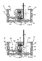
Fig. 3 is a cross-sectional view in a larger scale according to the line III-III ofFig. 1 , showing the aforesaid device with linear motion control and drive means integrated according to a first exemplary embodiment, -
Fig. 4 is a cross-sectional view in a different scale of the aforesaid device, showing the same device with linear motion control and drive means integrated according to a second exemplary embodiment,
Fig. 5 is a cross-sectional view of a structural body of the device according to the invention, comprising two hollow linear guide beams, substantially identical, which are juxtaposed and secured side by side, in demountable manner, according to a first step of a first phase of implementation of the production process of the device according to the present invention, -
Fig. 6 is a view similar to the view ofFig. 5 , but showing a second step of said first phase of the production process of the device according to the invention, -
Fig. 7 is a view similar to the view ofFig. 3 , but showing a second phase of the production process of the device of the present invention. - The accompanying drawings show, purely by way of example, two different embodiments relative to the linear motion double guide unit device of the invention. However, as already stated, these different embodiments of said device differ from each other only in relation to the respective control and drive means for linear displacement of a slide assembly with respect to corresponding single rail rectilinear guide means. Therefore, principally, the description below refers to the device according to the invention, regardless of the particular embodiment of said control and drive means. Nonetheless, a brief description of the different embodiments of said control and drive means is provided below.
- With reference to the drawings, the linear motion double guide unit device, with linear motion integrated drive, according to the invention is indicated as a whole with 10.
- Said device 10 includes two linear motion guide units 10.1 mutually coupled in parallel and comprises, in particular, a structural body 10.2, wherein two hollow
linear guide beams 11, substantially identical, are mutually juxtaposed and secured side by side, in demountable manner, and extend parallel according to a longitudinal axis. Each hollowlinear guide beam 11 has a substantially horizontal bottom wall 11.1 and two substantially vertical lateral walls 11.2, which delimit a guide cavity 11.3. In particular, eachlinear guide beam 11 is formed by a single piece body, with a substantially equilateral U-shaped cross section, obtained by extrusion. Moreover, said single piece body is closed at the longitudinal ends thereof by means of respective heads 11.4. - It will be noted that each linear motion guide unit forms a structurally autonomous entity and comprises a respective beam of said two hollow
linear guide beams 11. Eachlinear guide beam 11 comprises, in turn, a single railrectilinear guide 12, extending parallel to said longitudinal axis and secured, in demountable manner, with respect to the bottom wall 11.1, along the longitudinal vertical median plane of the unit. - In each linear motion guide unit 10.1, a
corresponding slide assembly 13 is mounted sliding along the respectivesingle rail guide 12. Eachslide assembly 13 forms a structurally autonomous entity and includes an upper carriage part 13.1 and two lower saddles 13.20 integral with said carriage 13.1 and engaged by sliding with respect to the respective single railrectilinear guide 12. Ball races 13.3 are provided in each of said saddles 13.20 in an arrangement partly surrounding saidrectilinear guide 12. - Each
linear guide beam 11 has, on the outer lateral face of each of the two longitudinal lateral walls 11.2, a respective pair ofassembly grooves 14, extending for the entire length parallel to said longitudinal axis, mutually staggered in height, with an opening on the respective lateral wall 11.2 and wherein the area of the cross section of eachgroove 14 has a trend increasing toward the inside of the beam In the example shown, eachgroove 14 has a cross section substantially in the shape of a "T" lying on its side. - In the two linear motion guide units 10.1 mutually coupled in parallel, the two hollow
linear guide beams 11 have theassembly grooves 14 in opposed pairs and with their respective openings substantially mating. - In each of said two
longitudinal grooves 14 of a first of said two juxtaposedlinear guide beams 11 there is housed with clearance a respectivelongitudinal key 15, formed by a metal profile, with cross section substantially in the shape of a "T" lying on its side and of a length essentially corresponding to that of said firstlinear guide beam 11. Saidkey 15 has a shape complementary to that of saidgroove 14 in which it is inserted and is prevented from extraction in the transverse direction of the same groove. In saidkey 15 there is provided an arrangement of threaded holes 15.1, whose axes are mutually spaced in longitudinal direction according to a constant pitch and are directed parallel to the transverse direction with respect to saidgroove 14 in which thekey 15 is inserted. In said threaded holes 15.1 there are partially screwed the stems ofcorresponding assembly screws 16, which with the remaining part of their stem and their head partially occupy theopposite groove 14 in the other of said two juxtaposedlinear guide beams 11. - Moreover, in the opposed lateral wall 11.2 of the other of said two juxtaposed
linear guide beams 11, along the tworespective grooves 14 there are provided corresponding arrangements of mounting throughholes 17, with transverse axis and which communicate, on the one side, with the guide cavity 11.3 of said otherlinear guide beam 11 and, on the other side, with the relative groove. The axes of saidholes 17 of each arrangement are mutually spaced in longitudinal direction according to a constant pitch, corresponding to that of the axes of the holes 15.1 of akey 15. Theholes 17 of each arrangement correspond axially to the heads of saidscrews 16 that engage thegroove 14, in which the same holes emerge. Between the head of eachscrew 16 and thegroove 14 in which said head is housed there is interposed a corresponding washer 16.1. Said assembly screws 16 appropriately clamped mutually secure said two hollow linear guide beams 11, connecting them together in integral coupling and in parallel according to said longitudinal axis, producing a single structural body 10.2. - Moreover, said slides 13 of the two units 10.1 of the device 10 according to the invention are also mutually coupled, side by side, in parallel and integrally, through a pair of
transverse blocks 18, arranged bridging theslides 13 and secured with respect to the same in demountable manner. - For this purpose, each slide 13 has, in the upper face of the carriage 13.1 thereof, a pair of transverse grooves 13.2 extending for the entire width thereof. In each groove 13.2 there is inserted, through positive connection, a corresponding end of a respective
transverse block 18, arranged bridging the two coupledslide assemblies 13 and formed by a metal bar provided with assembly through holes 18.1 with axis essentially vertical and corresponding, for position, with respective through holes 13.4 provided in each carriage 13.1 of thesame slide 13. Corresponding assembly screws 18.2 are inserted, through said holes 18.1 of theblocks 18 and are clamped in said holes 13.4, so as to make saidsame slide assemblies 13 mutually integral by means of saidblocks 18 thus secured. - According to the present invention, said linear motion control and drive means are provided only in one of said linear motion guide units 10.1, as will be more apparent below.
- According to a first embodiment, said control and drive means are provided in a first of said linear motion guide units 10.1 and comprise a
flexible traction member 19, for example with toothed belt, which starting from one longitudinal end of the carriage 13.1, to which it is secured, partially surrounds two guide pulleys (not shown) respectively provided in proximity of each of the two ends of the correspondinglinear guide beam 11, with essentially transverse axis. Saidflexible member 19 is further secured to said carriage 13.1, with the other end thereof, forming a closed loop. Rotation control means (not shown), for example an electric gear motor, are kinematically connected to one of said pulleys, while the other pulley is mounted idle. - According to another embodiment, said control and drive means are provided in a first of said linear motion guide units 10.1 and comprise a screw/
nut screw mechanism 20, wherein the screw extends in the longitudinal direction of the correspondinglinear guide beam 11, is mounted axially fixed and rotating with respect to said beam and is kinematically connected with respect to rotation drive means, for example electric gear motor means (not shown). Said screw is engaged by helical coupling with respect to a nut screw, for example of the type with internally threaded nut, secured with respect to therespective slide assembly 13 of said first guide unit 10.1. - Moreover, as taught by the patent application no.
TO2009A000938 of 30.11.2009 - As is apparent from the above, said control and drive means for linear displacement of the
corresponding slide 13 are provided in only one of the two linear motion guide units 10.1, whoseslide 13 in turn drives with integral motion theslide 13 of the other coupled guide unit 10.1. It must be noted that in said other guide unit 10.1, without guide means, the structure of therespective slide 13 is structurally simplified and of lesser height. To compensate this reduction of height of theslide 13, in thebeam 11 of said other linear unit 10.1 there is provided in an integral body a raised double bottom 11.5, on which the respectivesingle rail guide 12 is secured in demountable manner. Operation of the double guide unit device 10 according to the present invention is apparent from the above. Therefore, further description thereof is omitted. - The production process of the linear motion double guide unit device according to the invention comprises the following assembly steps.
- A first part of the device 10 according to the invention is produced by mutually coupling in parallel two linear motion guide units 10.1 and, in particular, forming a structural body 10.2, wherein two hollow linear guide beams 11, substantially identical, are mutually juxtaposed and secured side by side, parallel according to a longitudinal axis, in demountable manner. For this purpose:
- there are produced two hollow linear guide beams 11, substantially identical to each other:
- each comprising a substantially horizontal bottom wall 11.1 and two substantially vertical lateral walls 11.2, which delimit a guide cavity 11.3, and
- each having, on at least an external face of a longitudinal lateral wall thereof 11.2, at least one
assembly groove 14, which runs along the entire length thereof parallel to said longitudinal axis, has the opening thereof on said face and wherein the area of the cross section has a height increasing toward the inside of the same beam,
- said two hollow linear guide beams 11 are juxtaposed side by side, in parallel according to a longitudinal axis, so that the
respective grooves 14 mutually correspond in pairs and the openings of the same grooves mate; - there is produced a key 15 having a length substantially corresponding to that of each
linear guide beam 11 and a shape corresponding to that of a respective groove of a first of said two juxtaposed linear guide beams 11, so as to be housed in said groove and to be prevented from extraction in the transverse direction of the same groove, - said key 15 is provided with an arrangement of threaded holes 15.1, whose axes are mutually spaced according to a pitch in longitudinal direction,
- in said arrangement of threaded holes 15.1 there is mounted a corresponding arrangement of assembly screws 16, whose stems are respectively partially screwed in said threaded holes 15.1,
- while in the opposed lateral wall 11.2 of the other of said two juxtaposed linear guide beams 11, along each
groove 14, there is provided a corresponding arrangement of mounting throughholes 17, which communicate, on one side, with the guide cavity 11.3 of said otherlinear guide beam 11 and, on the other side, with therelative groove 14, and whose axes are mutually spaced in longitudinal direction according to a pitch that corresponds to that of the axes of the threaded holes 15.1 of said key 15, - said key 15 is inserted in the
respective groove 14 of said firstlinear guide beam 11, so that:- the
screws 16 mounted in the same key are arranged according to axes parallel to the transverse direction with respect to saidgroove 14, - a part of the stem of each of said screws 16 is contained
in saidsame groove 14, while substantially the remaining part of the stem and the head are housed in theopposite groove 14 located in the other of said juxtaposed linear guide beams 11, - the head of each of said screws 16 corresponds to a respective mounting through
hole 17 provided in the other of said juxtaposed linear guide beams 11;
- the
- a clamping key tool C is inserted into said guide cavity 11.3 of said other
linear guide beam 11 and an appropriately shaped end thereof is made to pass through each of said mountingholes 17, so as to engage the corresponding head of oneassembly screw 16 at a time, and - operating said tool C each
assembly screw 16 is appropriately clamped, so as to mutually connect said two juxtaposed hollow linear guide beams 11, coupling them integrally and in parallel according to said longitudinal axis, forming the structural body 10.2. - Moreover, the two
slide assemblies 13 of the two units 10.1 of the device 10 according to the invention are mutually coupled, side by side, in parallel and integrally. - In particular, said two
slide assemblies 13 are coupled by means of a pair oftransverse blocks 18, arranged bridging the same slides and secured with respect thereto in demountable manner. - For this purpose, each slide assembly 13:
- is provided in the upper face of the
carriage 13,1 thereof with at least one transverse groove 13.2; - in each groove 13.2 there is inserted, through positive connection, a corresponding end of a respective
transverse block 18, formed by a metal bar provided with assembly through holes 18.1 with axis essentially vertical and corresponding, for position, with respective through holes 13.4 provided in the carriage 13.1 of eachslide assembly 13; - assembly screws 18.2 are inserted, through said holes 18.1 of the
blocks 16 and are clamped in said holes 13.4 in the carriage 13.1, by means of the key C, so as to make said same slide assemblies mutually integral. - As is apparent from the above, the linear motion double unit guide device, with linear motion integrated drive, according to the present invention and as claimed, allows the objects set forth above to be achieved in an advantageous manner.
- Also the production process of the device according to the invention, as described above and as claimed, allows the relative object set forth above to be achieved in an advantageous manner.
Claims (10)
- Linear motion double guide unit device, comprising a body extending according to a longitudinal axis and having two guide cavities (11.3) parallel to said axis, and two respective single rail rectilinear guides (12), each secured parallel to said axis on a wall (11.1) of a corresponding guide cavity (11.3) and comprising at least one slide assembly (13) mounted sliding along said two rectilinear guides (12) and including at least a carriage part (13.1) and at least two saddles (13.20) integral with said carriage and each engaged by sliding along a respective single rail rectilinear guide,- characterized in thatit includes two linear motion single guide units (10.1) mutually coupled in parallel and each comprising:- a hollow structural element (11) extending according to a longitudinal axis, hereinafter called linear guide beam (11), delimiting a respective guide cavity (11.3),- a single rail rectilinear guide (12), parallel to said axis and secured on the bottom wall (11.1) inside said guide cavity (11.3), and- a slide assembly (13) mounted sliding along said single rail guide (12) and including a carriage part (13.1) and at least one saddle (13.20), integral with said carriage and engaged for sliding with respect to said single rail guide,and in that
said two linear motion single guide units (10.1) mutually coupled form a structural body (10.2), wherein said hollow linear guide beams (11) are mutually juxtaposed and secured side by side, in demountable manner, and extend parallel according to said longitudinal axis. - The device according to claim 1, characterized in that:- each linear motion single guide unit (10.1) forms a structurally autonomous entity and comprises a respective of said two hollow linear guide beams (11);- each linear guide beam (11) comprises a single rail rectilinear guide (12), extending parallel to said longitudinal axis and secured, in demountable manner, with respect to said bottom wall (11.1) of the same beam;- in each linear motion single guide unit (10.1), a corresponding slide assembly (13) is mounted sliding along the respective single rail guide (12) and forms a structurally autonomous entity, including a carriage part (13.1) and at least one saddle (13.20), integral with said carriage (13.1) and engaged for sliding with respect to the corresponding single rail rectilinear guide (12).
- The device according to claim 1 and/or 2, characterized:- in that each linear guide beam (11) has, on an external lateral face of at least one of two longitudinal lateral walls thereof (11.2) delimiting said guide cavity (11.3), at least one assembly groove (14), extending for the entire length parallel to said longitudinal axis and having an opening on said external face,- in that in said two linear motion single guide units (10.1) mutually coupled in parallel, said two hollow linear guide beams (11) have the respective assembly grooves (14) in opposed pairs and with their openings substantially mating,- in that:- in at least one longitudinal groove (14) of a first of said two juxtaposed linear guide beams (11) there is housed a respective longitudinal key (15), prevented from extraction in the transverse direction of the same groove,- in said key (15) there is provided an arrangement of threaded holes (15.1), whose axes are mutually spaced in longitudinal direction and are directed parallel to the transverse direction with respect to said groove (14) in which the key (15) is inserted;- in said threaded holes (15.1) there are partially screwed the stems of corresponding assembly screws (16), which substantially with the remaining part of their stem and their head partially occupy the opposite groove (14) in the other of said two juxtaposed linear guide beams (11);so that said assembly screws (16) appropriately clamped mutually secure said two hollow linear guide beams (11), connecting them together in integral coupling and in parallel according to said longitudinal axis, producing a single structural body (10.2).
and in that:- in the opposed lateral wall (11.2) of the other of said two juxtaposed linear guide beams (11), along the groove (14) corresponding to that of said first linear guide beam (11) in which said key (15) is housed, there is provided an arrangement of mounting through holes (17), with transverse axis and which communicate, on the one side, with the guide cavity (11.3) of said other linear guide beam (11) and, on the other side, with the same groove (14);- the axes of said holes (17) are mutually spaced in longitudinal direction, with pitch corresponding to that of the axes of the holes (15.1)of said key (15), and the holes (17) of each arrangement of holes correspond axially to the head of said screws (16) that engage the groove (14), in which the same holes emerge, - The device according to one or more of the preceding claims, characterized in that said slide assemblies (13) of said two linear motion single guide units (10.1) are mutually coupled, side by side, in parallel and integrally, through means (18, 18.1, 18.2, 13.1, 13.2, 13.4) for joining the same in demountable manner.
- The device according to claim 4, characterized in that:- each slide assembly (13) has in the upper face of the carriage thereof (13.1) at least one groove (13,2);- in each groove (13.2) there is inserted a corresponding end of a respective block (18), arranged bridging the two coupled slide assemblies (13) and provided with assembly through holes (18.1) with axis essentially vertical and corresponding, for position, with respective threaded holes (13.4) provided in each carriage (13.1) of the same slide assembly (13);- corresponding assembly screws (18.2) are inserted, through said holes (18.1) of the blocks (18) and are clamped in said holes (13.4), so as to make said same slide assemblies (13) mutually integral by means of said blocks (18).
- The device according to claim 4 and/or 5, characterised in that means (19, 20) to control and drive the linear motion are provided in only one of said two linear motion single guide units (10.1), whose slide assembly (13) drives with integral motion the slide assembly (13) of the other coupled guide unit (10.1).
- A production process of a linear motion double guide unit device, with linear motion integrated drive, according to one or more of the preceding claims, characterized in that there are mutually coupled in parallel two linear motion single guide units (10.1), each comprising:- a hollow structural element (11) extending according to a longitudinal axis, hereinafter called linear guide beam (11), delimiting a guide cavity (11.3),- a single rail rectilinear guide (12), parallel to said axis and secured on the bottom wall (11.1) inside said guide cavity (11.3), and- a slide assembly (13) mounted sliding along said single rail guide (12) and including a carriage part (13.1) and at least one saddle (13.20), integral with said carriage and engaged for sliding with respect to said single rail guide,
and there is formed a structural body (10.2), wherein said two hollow linear guide beams (11) are mutually juxtaposed and secured side by side, parallel according to a longitudinal axis, in demountable manner. - The process according to claim 7, characterized in that it comprises the steps wherein:a) there are produced two hollow linear guide beams (11), in each of which:- there are formed a bottom wall (11.1) and two lateral walls (11.2), which delimit a guide cavity (11.3), and- on at least an external face of a longitudinal lateral wall thereof (11.2), there is formed at least one assembly groove (14), which runs along the entire length thereof parallel to said longitudinal axis and has the opening thereof on said face,b) said two hollow linear guide beams (11) are juxtaposed side by side, in parallel according to said longitudinal axis, so that the respective grooves (14) mutually correspond in pairs and the openings of the pairs of grooves mate;c) there is produced a key (15) having a length substantially corresponding to that of each linear guide beam (11) and a shape adapted to be housed in a respective groove (14) of a first of said two juxtaposed linear guide beams (11) and to be prevented from extraction in the transverse direction of the same groove,d) said key (15) is provided with an arrangement of threaded holes (15.1), whose axes are mutually spaced in longitudinal direction,e) in said arrangement of threaded holes (15.1) there is mounted a corresponding arrangement of assembly screws (16), whose stems are respectively partially screwed in said threaded holes (15.1),f) in the opposed lateral wall (11.2) of the other of said two juxtaposed linear guide beams (11), along each groove (14), there is provided a corresponding arrangement of mounting through holes (17), which communicate, on one side, with the guide cavity (11.3) of said other linear guide beam (11) and, on the other side, with the relative groove (14), and whose axes are mutually spaced in longitudinal direction and according to a pitch that corresponds to that between the axes of the threaded holes (15.1) of said key (15),g) said key (15) is inserted in the respective groove (14) of said first linear guide beam (11), so that:- the screws (16) mounted in the same key are arranged according to axes parallel to the transverse direction with respect to said groove (14),- a part of the stem of each of said screws (16) is contained in said same groove (14), while substantially the remaining part of the stem and the head are housed in the opposite groove (14) located in the other of said juxtaposed linear guide beams (11),- the head of each of said screws (16) corresponds to a respective mounting through hole (17) provided in the other of said juxtaposed linear guide beams (11);h) a clamping key tool (c) is inserted into said guide cavity (11.3) of said other linear guide beam (11) and an appropriately shaped end thereof is made to pass through each of said mounting holes (17), so as to engage the corresponding head of one assembly screw (16) at a time, andi) operating said tool (C) each assembly screw (16) is appropriately clamped, so as to mutually connect said two juxtaposed hollow linear guide beams (11), coupling them integrally and in parallel according to said longitudinal axis, forming a structural body (10.2).
- The process according to claim 7 and/or 8, characterized in that said two slide assemblies (13) of said two linear motion single guide units (10.1) are mutually coupled, side by side, in parallel and integrally.
- The process according to claim 9, characterized in that it comprises the steps wherein:- at least one block (18), composed of a metal bar provided with assembly through holes (18.1) corresponding, in position, with respective threaded holes (13.4) provided in the carriages (13.1) of said two slide assemblies (13), is arranged bridging said coupled slide assemblies (13), and- corresponding assembly screws (18.2) are inserted through said holes (18.1) of said at least one block (18) and are clamped in said holes (13.4) of said carriages (13.1), by means of a key tool (C), so as to make said same slide assemblies (13) mutually integral.
Applications Claiming Priority (1)
| Application Number | Priority Date | Filing Date | Title |
|---|---|---|---|
| ITTO2010A000195A IT1399966B1 (en) | 2009-11-30 | 2010-03-15 | DOUBLE UNIT DRIVER FOR LINEAR HANDLING AND RELATIVE PRODUCTION PROCEDURE |
Publications (2)
| Publication Number | Publication Date |
|---|---|
| EP2369192A1 EP2369192A1 (en) | 2011-09-28 |
| EP2369192B1 true EP2369192B1 (en) | 2013-07-03 |
Family
ID=44012506
Family Applications (1)
| Application Number | Title | Priority Date | Filing Date |
|---|---|---|---|
| EP11001932.0A Not-in-force EP2369192B1 (en) | 2010-03-15 | 2011-03-09 | Linear motion double guide unit device and relative production process |
Country Status (1)
| Country | Link |
|---|---|
| EP (1) | EP2369192B1 (en) |
Family Cites Families (2)
| Publication number | Priority date | Publication date | Assignee | Title |
|---|---|---|---|---|
| DE9011851U1 (en) * | 1990-08-16 | 1990-10-31 | Pies, Gerrit, 5650 Solingen | Linear guide system |
| FR2820070B1 (en) * | 2001-01-31 | 2003-04-25 | Jean Paul Coron | PROFILE BODY MONOBLOCK FOR INCLUDING A MOTOR COMPONENT AND LINEAR MODULE MADE FROM SUCH A BODY |
-
2011
- 2011-03-09 EP EP11001932.0A patent/EP2369192B1/en not_active Not-in-force
Also Published As
| Publication number | Publication date |
|---|---|
| EP2369192A1 (en) | 2011-09-28 |
Similar Documents
| Publication | Publication Date | Title |
|---|---|---|
| CN106239781B (en) | The closing unit of molding machine | |
| CN100403961C (en) | A drive device, preferably for a lifting column of a height-adjustable table, and a lifting column | |
| US8292040B2 (en) | Double screw elevator | |
| DE102010019681B4 (en) | Linear motion device with omega drive | |
| US20070209857A1 (en) | Actuator | |
| US20140346810A1 (en) | Air-guiding device for a vehicle | |
| US9452547B2 (en) | Block mold having moveable liner | |
| KR101280762B1 (en) | Rolling guide device and method of manufacturing the same | |
| KR101381457B1 (en) | Engagement chain type device for forward and backward movement operation | |
| JP6143142B1 (en) | High-precision extruder capable of constant feeding | |
| EP2369192A1 (en) | Linear motion double guide unit device and relative production process | |
| CN114483754B (en) | Open-close type fastening nut and die casting machine | |
| CN114505674B (en) | Pneumatic bolt type positioning and locking device | |
| CN212667179U (en) | Electric long sliding rail assembly | |
| WO2016131462A1 (en) | Hydraulic device | |
| CN120133410A (en) | A steel cage production device for supporting ring reinforcement | |
| CN217784138U (en) | Double-chain tensioning device | |
| KR20090078482A (en) | Clamping Device of Injection Molding Machine | |
| CN210552678U (en) | Motion guiding device of injection molding machine movable mould plate and injection molding machine | |
| CN222114220U (en) | Machine tool beam | |
| CN219188491U (en) | Manufacturing equipment for reinforced concrete pole reinforcement cage | |
| DE102014101246B4 (en) | Ball-bearing spindle provided with a support mechanism | |
| CN114839073A (en) | Resistance to compression detection device of hot work steel mould | |
| DE102007012057A1 (en) | Two plate-locking unit comprises a fixed mould clamping plate at a machine frame and a movable mould clamping plate guided at the machine frame | |
| CN219840516U (en) | Height-adjustable hanging box, pulley hanging box device and door system |
Legal Events
| Date | Code | Title | Description |
|---|---|---|---|
| PUAI | Public reference made under article 153(3) epc to a published international application that has entered the european phase |
Free format text: ORIGINAL CODE: 0009012 |
|
| AK | Designated contracting states |
Kind code of ref document: A1 Designated state(s): AL AT BE BG CH CY CZ DE DK EE ES FI FR GB GR HR HU IE IS IT LI LT LU LV MC MK MT NL NO PL PT RO RS SE SI SK SM TR |
|
| AX | Request for extension of the european patent |
Extension state: BA ME |
|
| 17P | Request for examination filed |
Effective date: 20111207 |
|
| GRAP | Despatch of communication of intention to grant a patent |
Free format text: ORIGINAL CODE: EPIDOSNIGR1 |
|
| GRAS | Grant fee paid |
Free format text: ORIGINAL CODE: EPIDOSNIGR3 |
|
| GRAA | (expected) grant |
Free format text: ORIGINAL CODE: 0009210 |
|
| AK | Designated contracting states |
Kind code of ref document: B1 Designated state(s): AL AT BE BG CH CY CZ DE DK EE ES FI FR GB GR HR HU IE IS IT LI LT LU LV MC MK MT NL NO PL PT RO RS SE SI SK SM TR |
|
| REG | Reference to a national code |
Ref country code: GB Ref legal event code: FG4D |
|
| REG | Reference to a national code |
Ref country code: AT Ref legal event code: REF Ref document number: 619961 Country of ref document: AT Kind code of ref document: T Effective date: 20130715 Ref country code: CH Ref legal event code: EP |
|
| REG | Reference to a national code |
Ref country code: IE Ref legal event code: FG4D |
|
| REG | Reference to a national code |
Ref country code: DE Ref legal event code: R096 Ref document number: 602011002153 Country of ref document: DE Effective date: 20130829 |
|
| PG25 | Lapsed in a contracting state [announced via postgrant information from national office to epo] |
Ref country code: SI Free format text: LAPSE BECAUSE OF FAILURE TO SUBMIT A TRANSLATION OF THE DESCRIPTION OR TO PAY THE FEE WITHIN THE PRESCRIBED TIME-LIMIT Effective date: 20130703 |
|
| REG | Reference to a national code |
Ref country code: AT Ref legal event code: MK05 Ref document number: 619961 Country of ref document: AT Kind code of ref document: T Effective date: 20130703 |
|
| REG | Reference to a national code |
Ref country code: NL Ref legal event code: VDEP Effective date: 20130703 |
|
| REG | Reference to a national code |
Ref country code: LT Ref legal event code: MG4D |
|
| PG25 | Lapsed in a contracting state [announced via postgrant information from national office to epo] |
Ref country code: HR Free format text: LAPSE BECAUSE OF FAILURE TO SUBMIT A TRANSLATION OF THE DESCRIPTION OR TO PAY THE FEE WITHIN THE PRESCRIBED TIME-LIMIT Effective date: 20130703 Ref country code: SE Free format text: LAPSE BECAUSE OF FAILURE TO SUBMIT A TRANSLATION OF THE DESCRIPTION OR TO PAY THE FEE WITHIN THE PRESCRIBED TIME-LIMIT Effective date: 20130703 Ref country code: LT Free format text: LAPSE BECAUSE OF FAILURE TO SUBMIT A TRANSLATION OF THE DESCRIPTION OR TO PAY THE FEE WITHIN THE PRESCRIBED TIME-LIMIT Effective date: 20130703 Ref country code: NO Free format text: LAPSE BECAUSE OF FAILURE TO SUBMIT A TRANSLATION OF THE DESCRIPTION OR TO PAY THE FEE WITHIN THE PRESCRIBED TIME-LIMIT Effective date: 20131003 Ref country code: IS Free format text: LAPSE BECAUSE OF FAILURE TO SUBMIT A TRANSLATION OF THE DESCRIPTION OR TO PAY THE FEE WITHIN THE PRESCRIBED TIME-LIMIT Effective date: 20131103 Ref country code: BE Free format text: LAPSE BECAUSE OF FAILURE TO SUBMIT A TRANSLATION OF THE DESCRIPTION OR TO PAY THE FEE WITHIN THE PRESCRIBED TIME-LIMIT Effective date: 20130703 Ref country code: AT Free format text: LAPSE BECAUSE OF FAILURE TO SUBMIT A TRANSLATION OF THE DESCRIPTION OR TO PAY THE FEE WITHIN THE PRESCRIBED TIME-LIMIT Effective date: 20130703 Ref country code: CY Free format text: LAPSE BECAUSE OF FAILURE TO SUBMIT A TRANSLATION OF THE DESCRIPTION OR TO PAY THE FEE WITHIN THE PRESCRIBED TIME-LIMIT Effective date: 20130619 Ref country code: PT Free format text: LAPSE BECAUSE OF FAILURE TO SUBMIT A TRANSLATION OF THE DESCRIPTION OR TO PAY THE FEE WITHIN THE PRESCRIBED TIME-LIMIT Effective date: 20131104 |
|
| PG25 | Lapsed in a contracting state [announced via postgrant information from national office to epo] |
Ref country code: LV Free format text: LAPSE BECAUSE OF FAILURE TO SUBMIT A TRANSLATION OF THE DESCRIPTION OR TO PAY THE FEE WITHIN THE PRESCRIBED TIME-LIMIT Effective date: 20130703 Ref country code: FI Free format text: LAPSE BECAUSE OF FAILURE TO SUBMIT A TRANSLATION OF THE DESCRIPTION OR TO PAY THE FEE WITHIN THE PRESCRIBED TIME-LIMIT Effective date: 20130703 Ref country code: PL Free format text: LAPSE BECAUSE OF FAILURE TO SUBMIT A TRANSLATION OF THE DESCRIPTION OR TO PAY THE FEE WITHIN THE PRESCRIBED TIME-LIMIT Effective date: 20130703 Ref country code: ES Free format text: LAPSE BECAUSE OF FAILURE TO SUBMIT A TRANSLATION OF THE DESCRIPTION OR TO PAY THE FEE WITHIN THE PRESCRIBED TIME-LIMIT Effective date: 20131014 Ref country code: NL Free format text: LAPSE BECAUSE OF FAILURE TO SUBMIT A TRANSLATION OF THE DESCRIPTION OR TO PAY THE FEE WITHIN THE PRESCRIBED TIME-LIMIT Effective date: 20130703 Ref country code: GR Free format text: LAPSE BECAUSE OF FAILURE TO SUBMIT A TRANSLATION OF THE DESCRIPTION OR TO PAY THE FEE WITHIN THE PRESCRIBED TIME-LIMIT Effective date: 20131004 |
|
| PG25 | Lapsed in a contracting state [announced via postgrant information from national office to epo] |
Ref country code: CY Free format text: LAPSE BECAUSE OF FAILURE TO SUBMIT A TRANSLATION OF THE DESCRIPTION OR TO PAY THE FEE WITHIN THE PRESCRIBED TIME-LIMIT Effective date: 20130703 |
|
| PG25 | Lapsed in a contracting state [announced via postgrant information from national office to epo] |
Ref country code: RO Free format text: LAPSE BECAUSE OF FAILURE TO SUBMIT A TRANSLATION OF THE DESCRIPTION OR TO PAY THE FEE WITHIN THE PRESCRIBED TIME-LIMIT Effective date: 20130703 Ref country code: SK Free format text: LAPSE BECAUSE OF FAILURE TO SUBMIT A TRANSLATION OF THE DESCRIPTION OR TO PAY THE FEE WITHIN THE PRESCRIBED TIME-LIMIT Effective date: 20130703 Ref country code: EE Free format text: LAPSE BECAUSE OF FAILURE TO SUBMIT A TRANSLATION OF THE DESCRIPTION OR TO PAY THE FEE WITHIN THE PRESCRIBED TIME-LIMIT Effective date: 20130703 Ref country code: DK Free format text: LAPSE BECAUSE OF FAILURE TO SUBMIT A TRANSLATION OF THE DESCRIPTION OR TO PAY THE FEE WITHIN THE PRESCRIBED TIME-LIMIT Effective date: 20130703 Ref country code: CZ Free format text: LAPSE BECAUSE OF FAILURE TO SUBMIT A TRANSLATION OF THE DESCRIPTION OR TO PAY THE FEE WITHIN THE PRESCRIBED TIME-LIMIT Effective date: 20130703 |
|
| PLBE | No opposition filed within time limit |
Free format text: ORIGINAL CODE: 0009261 |
|
| STAA | Information on the status of an ep patent application or granted ep patent |
Free format text: STATUS: NO OPPOSITION FILED WITHIN TIME LIMIT |
|
| 26N | No opposition filed |
Effective date: 20140404 |
|
| REG | Reference to a national code |
Ref country code: DE Ref legal event code: R097 Ref document number: 602011002153 Country of ref document: DE Effective date: 20140404 |
|
| REG | Reference to a national code |
Ref country code: DE Ref legal event code: R119 Ref document number: 602011002153 Country of ref document: DE |
|
| PG25 | Lapsed in a contracting state [announced via postgrant information from national office to epo] |
Ref country code: LU Free format text: LAPSE BECAUSE OF FAILURE TO SUBMIT A TRANSLATION OF THE DESCRIPTION OR TO PAY THE FEE WITHIN THE PRESCRIBED TIME-LIMIT Effective date: 20140309 |
|
| REG | Reference to a national code |
Ref country code: CH Ref legal event code: PL |
|
| REG | Reference to a national code |
Ref country code: FR Ref legal event code: ST Effective date: 20141128 |
|
| REG | Reference to a national code |
Ref country code: IE Ref legal event code: MM4A Ref country code: DE Ref legal event code: R119 Ref document number: 602011002153 Country of ref document: DE Effective date: 20141001 |
|
| PG25 | Lapsed in a contracting state [announced via postgrant information from national office to epo] |
Ref country code: IE Free format text: LAPSE BECAUSE OF NON-PAYMENT OF DUE FEES Effective date: 20140309 Ref country code: CH Free format text: LAPSE BECAUSE OF NON-PAYMENT OF DUE FEES Effective date: 20140331 Ref country code: FR Free format text: LAPSE BECAUSE OF NON-PAYMENT OF DUE FEES Effective date: 20140331 Ref country code: LI Free format text: LAPSE BECAUSE OF NON-PAYMENT OF DUE FEES Effective date: 20140331 Ref country code: DE Free format text: LAPSE BECAUSE OF NON-PAYMENT OF DUE FEES Effective date: 20141001 |
|
| PGFP | Annual fee paid to national office [announced via postgrant information from national office to epo] |
Ref country code: IT Payment date: 20150324 Year of fee payment: 5 |
|
| GBPC | Gb: european patent ceased through non-payment of renewal fee |
Effective date: 20150309 |
|
| PG25 | Lapsed in a contracting state [announced via postgrant information from national office to epo] |
Ref country code: GB Free format text: LAPSE BECAUSE OF NON-PAYMENT OF DUE FEES Effective date: 20150309 |
|
| PG25 | Lapsed in a contracting state [announced via postgrant information from national office to epo] |
Ref country code: MT Free format text: LAPSE BECAUSE OF FAILURE TO SUBMIT A TRANSLATION OF THE DESCRIPTION OR TO PAY THE FEE WITHIN THE PRESCRIBED TIME-LIMIT Effective date: 20130703 |
|
| PG25 | Lapsed in a contracting state [announced via postgrant information from national office to epo] |
Ref country code: SM Free format text: LAPSE BECAUSE OF FAILURE TO SUBMIT A TRANSLATION OF THE DESCRIPTION OR TO PAY THE FEE WITHIN THE PRESCRIBED TIME-LIMIT Effective date: 20130703 |
|
| PG25 | Lapsed in a contracting state [announced via postgrant information from national office to epo] |
Ref country code: MC Free format text: LAPSE BECAUSE OF FAILURE TO SUBMIT A TRANSLATION OF THE DESCRIPTION OR TO PAY THE FEE WITHIN THE PRESCRIBED TIME-LIMIT Effective date: 20130703 |
|
| PG25 | Lapsed in a contracting state [announced via postgrant information from national office to epo] |
Ref country code: RS Free format text: LAPSE BECAUSE OF FAILURE TO SUBMIT A TRANSLATION OF THE DESCRIPTION OR TO PAY THE FEE WITHIN THE PRESCRIBED TIME-LIMIT Effective date: 20130703 Ref country code: BG Free format text: LAPSE BECAUSE OF FAILURE TO SUBMIT A TRANSLATION OF THE DESCRIPTION OR TO PAY THE FEE WITHIN THE PRESCRIBED TIME-LIMIT Effective date: 20130703 |
|
| PG25 | Lapsed in a contracting state [announced via postgrant information from national office to epo] |
Ref country code: TR Free format text: LAPSE BECAUSE OF FAILURE TO SUBMIT A TRANSLATION OF THE DESCRIPTION OR TO PAY THE FEE WITHIN THE PRESCRIBED TIME-LIMIT Effective date: 20130703 Ref country code: HU Free format text: LAPSE BECAUSE OF FAILURE TO SUBMIT A TRANSLATION OF THE DESCRIPTION OR TO PAY THE FEE WITHIN THE PRESCRIBED TIME-LIMIT; INVALID AB INITIO Effective date: 20110309 |
|
| PG25 | Lapsed in a contracting state [announced via postgrant information from national office to epo] |
Ref country code: IT Free format text: LAPSE BECAUSE OF NON-PAYMENT OF DUE FEES Effective date: 20160309 |
|
| PG25 | Lapsed in a contracting state [announced via postgrant information from national office to epo] |
Ref country code: MK Free format text: LAPSE BECAUSE OF FAILURE TO SUBMIT A TRANSLATION OF THE DESCRIPTION OR TO PAY THE FEE WITHIN THE PRESCRIBED TIME-LIMIT Effective date: 20130703 |
|
| PG25 | Lapsed in a contracting state [announced via postgrant information from national office to epo] |
Ref country code: AL Free format text: LAPSE BECAUSE OF FAILURE TO SUBMIT A TRANSLATION OF THE DESCRIPTION OR TO PAY THE FEE WITHIN THE PRESCRIBED TIME-LIMIT Effective date: 20130703 |