EP2369147A1 - Filter mounting structure for internal combustion engine - Google Patents
Filter mounting structure for internal combustion engine Download PDFInfo
- Publication number
- EP2369147A1 EP2369147A1 EP11150990A EP11150990A EP2369147A1 EP 2369147 A1 EP2369147 A1 EP 2369147A1 EP 11150990 A EP11150990 A EP 11150990A EP 11150990 A EP11150990 A EP 11150990A EP 2369147 A1 EP2369147 A1 EP 2369147A1
- Authority
- EP
- European Patent Office
- Prior art keywords
- filter
- gasket
- holding portion
- exhaust
- piping
- Prior art date
- Legal status (The legal status is an assumption and is not a legal conclusion. Google has not performed a legal analysis and makes no representation as to the accuracy of the status listed.)
- Granted
Links
Images


Classifications
-
- F—MECHANICAL ENGINEERING; LIGHTING; HEATING; WEAPONS; BLASTING
- F01—MACHINES OR ENGINES IN GENERAL; ENGINE PLANTS IN GENERAL; STEAM ENGINES
- F01N—GAS-FLOW SILENCERS OR EXHAUST APPARATUS FOR MACHINES OR ENGINES IN GENERAL; GAS-FLOW SILENCERS OR EXHAUST APPARATUS FOR INTERNAL-COMBUSTION ENGINES
- F01N13/00—Exhaust or silencing apparatus characterised by constructional features
- F01N13/18—Construction facilitating manufacture, assembly, or disassembly
- F01N13/1805—Fixing exhaust manifolds, exhaust pipes or pipe sections to each other, to engine or to vehicle body
- F01N13/1827—Sealings specially adapted for exhaust systems
-
- F—MECHANICAL ENGINEERING; LIGHTING; HEATING; WEAPONS; BLASTING
- F01—MACHINES OR ENGINES IN GENERAL; ENGINE PLANTS IN GENERAL; STEAM ENGINES
- F01N—GAS-FLOW SILENCERS OR EXHAUST APPARATUS FOR MACHINES OR ENGINES IN GENERAL; GAS-FLOW SILENCERS OR EXHAUST APPARATUS FOR INTERNAL-COMBUSTION ENGINES
- F01N3/00—Exhaust or silencing apparatus having means for purifying, rendering innocuous, or otherwise treating exhaust
- F01N3/02—Exhaust or silencing apparatus having means for purifying, rendering innocuous, or otherwise treating exhaust for cooling, or for removing solid constituents of, exhaust
- F01N3/021—Exhaust or silencing apparatus having means for purifying, rendering innocuous, or otherwise treating exhaust for cooling, or for removing solid constituents of, exhaust by means of filters
- F01N3/0211—Arrangements for mounting filtering elements in housing, e.g. with means for compensating thermal expansion or vibration
-
- F—MECHANICAL ENGINEERING; LIGHTING; HEATING; WEAPONS; BLASTING
- F01—MACHINES OR ENGINES IN GENERAL; ENGINE PLANTS IN GENERAL; STEAM ENGINES
- F01N—GAS-FLOW SILENCERS OR EXHAUST APPARATUS FOR MACHINES OR ENGINES IN GENERAL; GAS-FLOW SILENCERS OR EXHAUST APPARATUS FOR INTERNAL-COMBUSTION ENGINES
- F01N3/00—Exhaust or silencing apparatus having means for purifying, rendering innocuous, or otherwise treating exhaust
- F01N3/02—Exhaust or silencing apparatus having means for purifying, rendering innocuous, or otherwise treating exhaust for cooling, or for removing solid constituents of, exhaust
- F01N3/021—Exhaust or silencing apparatus having means for purifying, rendering innocuous, or otherwise treating exhaust for cooling, or for removing solid constituents of, exhaust by means of filters
- F01N3/022—Exhaust or silencing apparatus having means for purifying, rendering innocuous, or otherwise treating exhaust for cooling, or for removing solid constituents of, exhaust by means of filters characterised by specially adapted filtering structure, e.g. honeycomb, mesh or fibrous
- F01N3/0226—Exhaust or silencing apparatus having means for purifying, rendering innocuous, or otherwise treating exhaust for cooling, or for removing solid constituents of, exhaust by means of filters characterised by specially adapted filtering structure, e.g. honeycomb, mesh or fibrous the structure being fibrous
-
- F—MECHANICAL ENGINEERING; LIGHTING; HEATING; WEAPONS; BLASTING
- F02—COMBUSTION ENGINES; HOT-GAS OR COMBUSTION-PRODUCT ENGINE PLANTS
- F02M—SUPPLYING COMBUSTION ENGINES IN GENERAL WITH COMBUSTIBLE MIXTURES OR CONSTITUENTS THEREOF
- F02M26/00—Engine-pertinent apparatus for adding exhaust gases to combustion-air, main fuel or fuel-air mixture, e.g. by exhaust gas recirculation [EGR] systems
- F02M26/02—EGR systems specially adapted for supercharged engines
- F02M26/04—EGR systems specially adapted for supercharged engines with a single turbocharger
- F02M26/05—High pressure loops, i.e. wherein recirculated exhaust gas is taken out from the exhaust system upstream of the turbine and reintroduced into the intake system downstream of the compressor
-
- F—MECHANICAL ENGINEERING; LIGHTING; HEATING; WEAPONS; BLASTING
- F02—COMBUSTION ENGINES; HOT-GAS OR COMBUSTION-PRODUCT ENGINE PLANTS
- F02M—SUPPLYING COMBUSTION ENGINES IN GENERAL WITH COMBUSTIBLE MIXTURES OR CONSTITUENTS THEREOF
- F02M26/00—Engine-pertinent apparatus for adding exhaust gases to combustion-air, main fuel or fuel-air mixture, e.g. by exhaust gas recirculation [EGR] systems
- F02M26/02—EGR systems specially adapted for supercharged engines
- F02M26/04—EGR systems specially adapted for supercharged engines with a single turbocharger
- F02M26/06—Low pressure loops, i.e. wherein recirculated exhaust gas is taken out from the exhaust downstream of the turbocharger turbine and reintroduced into the intake system upstream of the compressor
-
- F—MECHANICAL ENGINEERING; LIGHTING; HEATING; WEAPONS; BLASTING
- F02—COMBUSTION ENGINES; HOT-GAS OR COMBUSTION-PRODUCT ENGINE PLANTS
- F02M—SUPPLYING COMBUSTION ENGINES IN GENERAL WITH COMBUSTIBLE MIXTURES OR CONSTITUENTS THEREOF
- F02M26/00—Engine-pertinent apparatus for adding exhaust gases to combustion-air, main fuel or fuel-air mixture, e.g. by exhaust gas recirculation [EGR] systems
- F02M26/13—Arrangement or layout of EGR passages, e.g. in relation to specific engine parts or for incorporation of accessories
- F02M26/14—Arrangement or layout of EGR passages, e.g. in relation to specific engine parts or for incorporation of accessories in relation to the exhaust system
- F02M26/15—Arrangement or layout of EGR passages, e.g. in relation to specific engine parts or for incorporation of accessories in relation to the exhaust system in relation to engine exhaust purifying apparatus
-
- F—MECHANICAL ENGINEERING; LIGHTING; HEATING; WEAPONS; BLASTING
- F01—MACHINES OR ENGINES IN GENERAL; ENGINE PLANTS IN GENERAL; STEAM ENGINES
- F01N—GAS-FLOW SILENCERS OR EXHAUST APPARATUS FOR MACHINES OR ENGINES IN GENERAL; GAS-FLOW SILENCERS OR EXHAUST APPARATUS FOR INTERNAL-COMBUSTION ENGINES
- F01N2330/00—Structure of catalyst support or particle filter
- F01N2330/10—Fibrous material, e.g. mineral or metallic wool
-
- Y—GENERAL TAGGING OF NEW TECHNOLOGICAL DEVELOPMENTS; GENERAL TAGGING OF CROSS-SECTIONAL TECHNOLOGIES SPANNING OVER SEVERAL SECTIONS OF THE IPC; TECHNICAL SUBJECTS COVERED BY FORMER USPC CROSS-REFERENCE ART COLLECTIONS [XRACs] AND DIGESTS
- Y02—TECHNOLOGIES OR APPLICATIONS FOR MITIGATION OR ADAPTATION AGAINST CLIMATE CHANGE
- Y02T—CLIMATE CHANGE MITIGATION TECHNOLOGIES RELATED TO TRANSPORTATION
- Y02T10/00—Road transport of goods or passengers
- Y02T10/10—Internal combustion engine [ICE] based vehicles
- Y02T10/12—Improving ICE efficiencies
Definitions
- the present invention relates to a filter mounting structure for an internal combustion engine, for mounting a filter for removing foreign matter from exhaust gases, on an exhaust piping through which exhaust gases from the engine flow.
- Japanese Laid-Open Patent Publication (Kokai) No. H07-71329 discloses provision of a filter for removing foreign matter, such as carbon, from exhaust gases, in an EGR passage for recirculating part of exhaust gases from the engine into an intake pipe.
- FIG. 6 Conventionly, when a light and thin metal filter is mounted on an exhaust piping, there has been widely used a mounting structure shown in FIG. 6 so as to enable the filter to withstand high-temperature, high-flow rate exhaust gases.
- flanges 52 and 52 (only one of which is shown) are provided at a juncture of two exhaust pipes 51 and 51 (only one of which is shown), such that the flanges 52 and 52 are opposed to each other, and two gaskets 53 and 53 are interposed between the flanges 52 and 52.
- an outer peripheral portion of a filter 54 is inserted between the gaskets 53 and 53.
- the flanges 52 and 52 are fastened by a fastener (not shown), whereby the gaskets 53 and 53 are crushed for sandwiching the filter 54. This fixes the filter 54 in a state sealed by the gaskets 53 and 53.
- the filter 54 exists between portions of the flanges 52 and 52 closer to the respective exhaust pipes 51 and 51, the total thickness of these portions is larger than the total thickness of portions outward of these portions by the thickness of the filter 54. Therefore, when the gaskets 53 and 53 are crushed by fastening the flanges 52 and 52, the portions of the flanges 52 and 52 closer to the respective exhaust pipes 51 and 51 are sometimes deformed by the difference between the total thicknesses (by the thickness of the filter 54). In this case, there is a fear that sealing property is degraded by the deformation, causing leakage of exhaust gases from between the surfaces of the deformed flanges 52 and 52.
- the present invention provides a filter mounting structure for an internal combustion engine, for mounting, on exhaust piping through which flow exhaust gases discharged from the engine, a metal filter for removing foreign matter from the exhaust gases, including a pair of flanges provided on an end of the exhaust piping and a piping member to which the end of the exhaust piping is connected, respectively, in a manner opposed to each other, and a gasket sandwiched between the pair of flanges, characterized in that the gasket comprises a sealing portion that is disposed outward of an outer peripheral surface of the exhaust piping in a manner spaced therefrom and is sandwiched between the pair of flanges, for sealing exhaust gases, and a holding portion that extends inwardly from the sealing portion to a vicinity of the outer peripheral surface of the exhaust piping and holds the filter in a state where an outer peripheral portion of the filter is engaged with the holding portion, wherein a thickness of the sealing portion of the gasket is set to be not smaller than a total thickness of the holding portion, which is
- the pair of flanges are provided on the end of the exhaust piping on which the filter should be mounted and the piping member to which the end of the exhaust piping is connected, respectively, in a manner opposed to each other.
- the gasket is sandwiched between the flanges.
- the gasket includes the sealing portion disposed outward of the outer peripheral surface of the exhaust piping in a manner spaced therefrom, and the sealing portion seals exhaust gases by being sandwiched between the pair of flanges.
- the gasket includes the holding portion extending inwardly from the sealing portion to the vicinity of the outer peripheral surface of the exhaust piping, and the holding portion holds the filter by having the outer peripheral portion of the filter engaged therewith.
- the thickness of the sealing portion of the gasket is set to be not smaller than the total thickness of the holding portion, which is the sum of the respective thicknesses of the filter and the holding portion. Because of the above-described relationship between the thicknesses, even in a state where the sealing portion of the gasket is crushed, portions of the flanges corresponding to the holding portion are not deformed. This makes it possible to improve the sealing property of the holding portion to positively prevent exhaust gases from leaking from the holding portion. Further, the basic construction that the filter is mounted by sandwiching the gasket between the pair of flanges is not different from the above-described general mounting structure, so that it is possible to obtain the above-described advantageous effects while maintaining such a simple construction.
- the filter is a metal mesh filter
- the filter mounting structure further comprises a frame that is mounted on an outer peripheral portion of the mesh filter in a manner covering the outer peripheral portion and is engaged with the holding portion of the gasket, wherein the thickness of the sealing portion of the gasket is set to be not smaller than the total thickness of the holding portion, which is a sum of respective thicknesses of the filter, the holding portion, and the frame.
- the metal mesh filter is advantageous in that it is capable of removing foreign matter by a simple construction, there is a fear that due to engagement of the outer peripheral portion of the metal mesh filter with the holding portion of the gasket, metal wires drop off the filter, and are caught in gaps between the gasket and the flanges, which can result in the degraded sealing property.
- the outer peripheral portion of the mesh filter is covered by the frame, and is engaged with the holding portion of the gasket via the frame, so that the metal wires can be prevented from dropping off the filter, and therefore it is possible to maintain an excellent sealing property.
- the thickness of the sealing portion of the gasket is set to be not smaller than the total thickness of the holding portion, which is the sum of the respective thicknesses of the filter, the holding portion, and the frame, and hence even in the state where the sealing portion of the gasket is crushed, the portions of the flanges corresponding to the holding portion of the gasket are not deformed. Therefore, the above-described advantageous effects can also be obtained.
- the holding portion of the gasket includes upstream-side and downstream-side extending portions extending inwardly from the sealing portion in a state spaced from each other in a direction of flow of exhaust gases, the outer peripheral portion of the filter being engaged between the upstream-side and downstream-side extending portions, wherein the thickness of the sealing portion of the gasket is set to be larger than the total thickness of the holding portion, and wherein the upstream-side extending portion of the holding portion has a cover portion formed in a manner inclined toward a downstream side of exhaust gases such that the cover portion covers a gap between the upstream-side extending portion and the filter.
- the holding portion of the gasket includes the upstream-side and downstream-side extending portions provided in the direction of flow of exhaust gases in the state spaced from each other.
- the outer peripheral portion of the filter is engaged between the upstream-side and downstream-side extending portions.
- the thickness of the sealing portion of the gasket is set to be larger than the total thickness of the holding portion. This forms a gap between the upstream-side extending portion of the holding portion and the filter. As a consequence, foreign matter in exhaust gases can flow into this gap, and further enter the gaps between the gasket and the flanges, thereby degrading the sealing property.
- the upstream-side extending portion of the holding portion has the cover portion formed in a manner inclined toward the downstream side of exhaust gases such that it covers the gap between the upstream-side extending portion and the filter. This makes it possible to prevent foreign matter from flowing into the gap, and therefore it is possible to maintain an excellent sealing property.
- the exhaust piping is provided with a turbine for a supercharger for driving a compressor for the supercharger, the compressor being disposed in intake piping for sucking fresh air into the engine, a purifying device for purifying exhaust gases, and an exhaust gas recirculation pipe that branches from a portion of the exhaust piping downstream of the purifying device and joins a portion of the intake piping upstream of the compressor, for recirculating part of exhaust gases into the intake piping, and wherein the filter is mounted on the exhaust gas recirculation pipe.
- the exhaust gas recirculation pipe is connected to a portion of the exhaust piping downstream of the purifying device and a portion of the intake piping upstream of the compressor for the supercharger.
- the filter is mounted on the exhaust gas recirculation pipe. This makes it possible to trap oxides generated in the purifying device and broken pieces dropped off the purifying device in the filter, thereby positively preventing the foreign matter from flowing into the compressor, and preventing damage or breakage of the compressor from occurring due to the foreign matter flowing into the compressor.
- an internal combustion engine (hereinafter referred to as the "engine") 1 is a diesel engine for a vehicle (not shown), which has four cylinders 3.
- Intake piping 4 and exhaust piping 5 are connected to the cylinders 3.
- the intake piping 4 comprises an intake pipe 6, and an intake manifold 8 connected to the intake pipe 6 via an intake chamber 7.
- the intake manifold 8 is connected to the cylinders 3.
- the intake pipe 6 is provided with a throttle valve 9, a compressor 11 of a turbocharger 10, and an intercooler 12, at respective locations from upstream to downstream in the mentioned order.
- the throttle valve 9 is actuated by an actuator (not shown), for adjustment of the amount of fresh air sucked into each cylinder 3.
- the compressor 11 is driven by a turbine 21, referred to hereinafter, for supercharging intake air.
- the intercooler 12 cools the intake air the temperature of which has been raised by the supercharging operation of the compressor 11.
- the exhaust piping 5 comprises an exhaust manifold 13 connected to each cylinder 3, an exhaust pipe 14 connected to the downstream side of the exhaust manifold 13, and a high-pressure EGR pipe 15 and a low-pressure EGR pipe 16 which are connected in parallel with each other between the exhaust pipe 14 and the intake pipe 6.
- the exhaust pipe 14 is provided with the turbine 21 of the turbocharger 10, a NOx catalyst 22, and a DPF (Diesel Particulate Filter) 23, at respective locations from upstream to downstream in the mentioned order.
- the turbine 21 is driven by exhaust gases flowing through the exhaust pipe 14, for causing the compressor 11 to rotate in unison via a turbine shaft 21a such that the compressor 11 performs the supercharging operation.
- the NOx catalyst 22 carries a zeolite or the like thereon.
- the NOx catalyst 22 traps NOx contained in exhaust gases during the lean operation of the engine 1, and releases the trapped NOx in the reduced state by being supplied with reducing agent e.g. during the rich operation of the engine 1, to thereby purify the exhaust gases.
- the DPF 23 comprises a ceramic, and purifies the exhaust gases by collecting particulates, such as soot, from exhaust gases.
- the high-pressure EGR pipe 15 branches from a portion of the exhaust pipe 14 upstream of the turbine 21, and joins a portion of the intake pipe 6 downstream of the intercooler 12. This recirculates high-temperature, high-pressure exhaust gases into the intake pipe 6 as high-pressure EGR gas via the high-pressure EGR pipe 15.
- the high-pressure EGR pipe 15 is provided with a high-pressure EGR control valve 24 for controlling the amount of high-pressure EGR gas.
- the low-pressure EGR pipe 16 branches from a portion of the exhaust pipe 14 downstream of the DPF 23, and joins a portion of the intake pipe 6 upstream of the compressor 11. This recirculates lower-temperature, lower-pressure exhaust gases than the high-pressure EGR gas as low-pressure EGR gas into the intake pipe 6 via the low-pressure EGR pipe 16.
- the low-pressure EGR pipe 16 is provided with a filter 25 for trapping foreign matter contained in the low-pressure EGR gas, an EGR cooler 26 for cooling the low-pressure EGR gas, and a low-pressure EGR control valve 27 for controlling the amount of the low-pressure EGR gas, from upstream to downstream of exhaust gases (from the DPF 23 toward the intake pipe 6) in the mentioned order.
- the foreign matter in the low-pressure EGR gas includes not only oxides generated on the downstream side of the DPF 23 but also ceramic pieces dropped off the DPF 23, etc.
- the filter 25 is a metal mesh filter having shape retainability, and comprises a filter body 25a having a hemispherical shape, and a brim-shaped mounting portion 25b extending continuous with the filter body 25a circumferentially along the outer periphery thereof.
- the filter 25 is mounted on a portion where a connecting pipe 28 that protrudes from a casing 23a accommodating the DPF 23 and the low-pressure EGR pipe 16 are connected, in a state where the filter body 25a blocks a passage extending through the low-pressure EGR pipe 16 with an opening of the filter body 25a facing upstream.
- the filter 25 is mounted using a pair of flanges 31 and 31, a gasket 32 and a frame 33.
- Each flange 31 is formed e.g. by a steel plate, and has a relatively thick annular plate-shape.
- the pair of flanges 31 and 31 are fixed to respective ends of the low-pressure EGR pipe 16 and the connecting pipe 28, and are arranged in a manner opposed to each other.
- the flanges 31 and 31 are fastened by fastening tools 34, such as bolts and nuts.
- the gasket 32 also has an annular plate-shape, and is sandwiched between the fastened flanges 31 and 31.
- the gasket 32 is formed by partially joining and laminating five sheets 32a made e.g. of stainless steel plates. Out of five layers of the sheets 32a, three layers except the top and bottom layers are arranged in a manner spaced outward from an outer peripheral surface of the low-pressure EGR pipe 16. On the other hand, the top and bottom layers extend in a manner overlapping the three layers, and further inward beyond the inner ends of the three layers to the vicinity of the outer peripheral surface of the low-pressure EGR pipe 16.
- a sealing portion 32b is formed by an outer part of the gasket 32 made of the five sheet 32a overlapping each other. Further, the top and bottom layers 32a and 32a extending inwardly from the sealing portion 32b correspond to upstream-side and downstream-side extending portions 32c and 32c, by which is formed a holding portion 32d.
- the frame 33 is made e.g. of a stainless steel plate, and is mounted on a part of the filter 25 from a base portion of the filter body 25a to the mounting portion 25b along the whole length of the filter 25 in the circumferential direction. Further, the extreme end of the frame 33 is folded back into two so as to cover the mounting portion 25b of the filter 25 from opposite sides.
- the thickness t1 of the filter 25 is set to 0.3 mm
- the thickness t2 of each sheet 32a of the gasket 32 is set to 0.3 mm
- the thickness t3 of the frame 33 is set to 0.2 mm, for example.
- the mounting of the filter 25 using these component elements is carried out, for example, as follows: First, as shown in FIG. 3 , the gasket 32 is placed on the flange 31 provided on an end of the low-pressure EGR pipe 16. Next, the mounting portion 25b of the filter 25 having the frame 33 attached thereto is engaged between the extending portions 32c and 32c of the holding portion 32d of the gasket 32. Then, the end of the low-pressure EGR pipe 16 is aligned with an end of the connecting pipe 28, and the flanges 31 and 31 are fastened in a state opposed to each other by the fastening tools 34, whereby the assembly of the component elements and the mounting of the filter 25 are completed.
- the sealing portion 32b of the gasket 32 is crushed by fastening the flanges 31 and 31, whereby the mounting portion 25b of the filter 25 is sealed. Further, the holding portion 32d of the gasket 32 holds the filter 25 with the mounting portion 25b of the filter 25 engaged therewith.
- the sealing portion 32b of the gasket 32 disposed outward of the exhaust piping in a manner spaced therefrom is sandwiched between the flanges 31 and 31, and seals the mounting portion for the filter 25 in the crushed state. Further, the holding portion 32d of the gasket 32 disposed in the vicinity of the exhaust piping holds the filter 25 with the mounting portion 25b of the filter 25 engaged therewith.
- the thickness ts of the sealing portion 32b of the gasket 32 is set to be larger than the total thickness th of the holding portion 32d, which is the sum of the thicknesses of the filter 25, the holding portion 32d and the frame 33, and hence even in the state where the sealing portion 32b of the gasket 32 is crushed, portions of the flanges 31 corresponding to the holding portion 32d are not deformed. This makes it possible to improve the sealing property of the holding portion 32d to positively prevent exhaust gases from leaking from the holding portion 32d.
- the basic construction that the filter 25 is mounted by sandwiching the gasket 32 between the pair of flanges 31 and 31 is not different from the above-described general mounting structure, so that it is possible to obtain the above-described advantageous effects while maintaining such a simple construction.
- the mounting portion 25b of the filter 25 formed by a mesh filter is covered by the frame 33, and is engaged with the holding portion 32d of the gasket 32 via the frame 33. This makes it possible to prevent metal wires from dropping off the filter 25, thereby making it possible to maintain an excellent sealing property.
- the filter 25 is mounted on the low-pressure EGR pipe 16 that branches from the portion of the exhaust pipe 14 downstream of the DPF 23 and joins the portion of the intake pipe 6 upstream of the compressor 11 of the turbocharger 10. This makes it possible to trap oxides generated downstream of the DPF 23, ceramic pieces dropped off the DPF 23, and so forth, in the filter 25, so that it is possible to positively prevent these pieces of foreign matter from flowing into the compressor 11, and prevent damage or breakage of the compressor 11 from occurring due to the foreign matter flowing into the compressor 11.
- the upstream-side extending portion 32c of the holding portion 32d of the gasket 32 has a cover portion 32e formed in a manner inclined toward the downstream side of exhaust gases.
- the remainder of the construction of the variation is the same as that of the above-described embodiment.
- the gap G between the upstream-side extending portion 32c of the gasket 32 and the frame 33 enclosing the mounting portion 25b of the filter 25 is covered by the cover portion 32e, it is possible to prevent foreign matter from flowing into the gap G, and therefore, it is possible to maintain an excellent sealing property.
- the present invention is by no means limited to the embodiment described above, but can be practiced in various forms.
- the thickness ts of the sealing portion 32b is set to a larger value than that of the total thickness th of the holding portion 32d
- the thickness ts of the sealing portion 32b may be set to the same value as that of the total thickness th. In this case as well, it is possible to obtain the same advantageous effects described above.
- the frame 33 is provided on the mounting portion 25b of the filter 25, the frame 33 may be omitted.
- the thickness ts of the sealing portion 32b is set to be not smaller than the total thickness th of the holding portion 32d (the sum of the thicknesses of the filter 25 and the holding portion 32d).
- the filter 25 is mounted on the low-pressure EGR pipe 16, the filter 25 may be mounted on another suitable portion of the exhaust piping 5, such as the high-pressure EGR pipe 15.
- the flange 31 toward the DPF 23 is formed on the connecting pipe 28 protruding from the casing 23a, it may be directly formed on the casing 23a.
- the gasket 32 is formed by the plurality of laminated sheets 32a, the gasket 32 may be integrally formed such that it includes a sealing portion and a holding portions which satisfy the requirements of the present invention.
- the present invention is applied to the diesel engine installed on an automotive vehicle by way of example, this is not limitative, but it can be applied to various types of engines, such as gasoline engines, and engines for other than automotive vehicles, such as engines for ship propulsion machines, e.g. an outboard motor having a vertically-disposed crankshaft.
- a filter mounting structure for an internal combustion engine capable of preventing deformation of flanges when mounting a filter on exhaust piping, thereby improving the sealing property of a filter-mounted portion and positively preventing leakage of exhaust gases, while maintaining a simple construction.
- a pair of flanges are provided on a low-pressure EGR pipe and a connecting pipe, respectively.
- a gasket is sandwiched between the flanges.
- the gasket has a sealing portion for sealing exhaust gases, disposed outward of the outer peripheral surface of the low-pressure EGR pipe in a manner spaced therefrom and sandwiched between the flanges, and a holding portion for holding the filter, engaged with the filter mounting portion and disposed inward of the sealing portion.
- the thickness of the sealing portion is set to be not smaller than the total thickness of the filter and the holding portion.
Landscapes
- Engineering & Computer Science (AREA)
- Chemical & Material Sciences (AREA)
- Combustion & Propulsion (AREA)
- Mechanical Engineering (AREA)
- General Engineering & Computer Science (AREA)
- Exhaust-Gas Circulating Devices (AREA)
- Supercharger (AREA)
- Processes For Solid Components From Exhaust (AREA)
Abstract
Description
- The present invention relates to a filter mounting structure for an internal combustion engine, for mounting a filter for removing foreign matter from exhaust gases, on an exhaust piping through which exhaust gases from the engine flow.
- Japanese Laid-Open Patent Publication (Kokai) No.
H07-71329 - Further, conventionally, when a light and thin metal filter is mounted on an exhaust piping, there has been widely used a mounting structure shown in
FIG. 6 so as to enable the filter to withstand high-temperature, high-flow rate exhaust gases. In this mounting structure,flanges 52 and 52 (only one of which is shown) are provided at a juncture of twoexhaust pipes 51 and 51 (only one of which is shown), such that theflanges gaskets flanges filter 54 is inserted between thegaskets flanges gaskets filter 54. This fixes thefilter 54 in a state sealed by thegaskets - In the above-described conventional mounting structure generally employed, since the
filter 54 exists between portions of theflanges respective exhaust pipes filter 54. Therefore, when thegaskets flanges flanges respective exhaust pipes deformed flanges - It is an object of the present invention to provide a filter mounting structure for an internal combustion engine, which is capable of preventing flanges from being deformed when a filter is mounted on exhaust piping, thereby improving the sealing property of a portion where the filter is mounted and positively preventing leakage of exhaust gases, while maintaining a simple construction.
- To attain the above object, the present invention provides a filter mounting structure for an internal combustion engine, for mounting, on exhaust piping through which flow exhaust gases discharged from the engine, a metal filter for removing foreign matter from the exhaust gases, including a pair of flanges provided on an end of the exhaust piping and a piping member to which the end of the exhaust piping is connected, respectively, in a manner opposed to each other, and a gasket sandwiched between the pair of flanges, characterized in that the gasket comprises a sealing portion that is disposed outward of an outer peripheral surface of the exhaust piping in a manner spaced therefrom and is sandwiched between the pair of flanges, for sealing exhaust gases, and a holding portion that extends inwardly from the sealing portion to a vicinity of the outer peripheral surface of the exhaust piping and holds the filter in a state where an outer peripheral portion of the filter is engaged with the holding portion, wherein a thickness of the sealing portion of the gasket is set to be not smaller than a total thickness of the holding portion, which is a sum of respective thicknesses of the filter and the holding portion.
- According to this filter mounting structure for an internal combustion engine, the pair of flanges are provided on the end of the exhaust piping on which the filter should be mounted and the piping member to which the end of the exhaust piping is connected, respectively, in a manner opposed to each other. The gasket is sandwiched between the flanges. The gasket includes the sealing portion disposed outward of the outer peripheral surface of the exhaust piping in a manner spaced therefrom, and the sealing portion seals exhaust gases by being sandwiched between the pair of flanges. Further, the gasket includes the holding portion extending inwardly from the sealing portion to the vicinity of the outer peripheral surface of the exhaust piping, and the holding portion holds the filter by having the outer peripheral portion of the filter engaged therewith.
- Further, according to the present invention, the thickness of the sealing portion of the gasket is set to be not smaller than the total thickness of the holding portion, which is the sum of the respective thicknesses of the filter and the holding portion. Because of the above-described relationship between the thicknesses, even in a state where the sealing portion of the gasket is crushed, portions of the flanges corresponding to the holding portion are not deformed. This makes it possible to improve the sealing property of the holding portion to positively prevent exhaust gases from leaking from the holding portion. Further, the basic construction that the filter is mounted by sandwiching the gasket between the pair of flanges is not different from the above-described general mounting structure, so that it is possible to obtain the above-described advantageous effects while maintaining such a simple construction.
- Preferably, the filter is a metal mesh filter, and the filter mounting structure further comprises a frame that is mounted on an outer peripheral portion of the mesh filter in a manner covering the outer peripheral portion and is engaged with the holding portion of the gasket, wherein the thickness of the sealing portion of the gasket is set to be not smaller than the total thickness of the holding portion, which is a sum of respective thicknesses of the filter, the holding portion, and the frame.
- Although the metal mesh filter is advantageous in that it is capable of removing foreign matter by a simple construction, there is a fear that due to engagement of the outer peripheral portion of the metal mesh filter with the holding portion of the gasket, metal wires drop off the filter, and are caught in gaps between the gasket and the flanges, which can result in the degraded sealing property. With the arrangement described above, the outer peripheral portion of the mesh filter is covered by the frame, and is engaged with the holding portion of the gasket via the frame, so that the metal wires can be prevented from dropping off the filter, and therefore it is possible to maintain an excellent sealing property. Further, the thickness of the sealing portion of the gasket is set to be not smaller than the total thickness of the holding portion, which is the sum of the respective thicknesses of the filter, the holding portion, and the frame, and hence even in the state where the sealing portion of the gasket is crushed, the portions of the flanges corresponding to the holding portion of the gasket are not deformed. Therefore, the above-described advantageous effects can also be obtained.
- Preferably, the holding portion of the gasket includes upstream-side and downstream-side extending portions extending inwardly from the sealing portion in a state spaced from each other in a direction of flow of exhaust gases, the outer peripheral portion of the filter being engaged between the upstream-side and downstream-side extending portions, wherein the thickness of the sealing portion of the gasket is set to be larger than the total thickness of the holding portion, and wherein the upstream-side extending portion of the holding portion has a cover portion formed in a manner inclined toward a downstream side of exhaust gases such that the cover portion covers a gap between the upstream-side extending portion and the filter.
- According to this arrangement, the holding portion of the gasket includes the upstream-side and downstream-side extending portions provided in the direction of flow of exhaust gases in the state spaced from each other. The outer peripheral portion of the filter is engaged between the upstream-side and downstream-side extending portions. Further, the thickness of the sealing portion of the gasket is set to be larger than the total thickness of the holding portion. This forms a gap between the upstream-side extending portion of the holding portion and the filter. As a consequence, foreign matter in exhaust gases can flow into this gap, and further enter the gaps between the gasket and the flanges, thereby degrading the sealing property. According to the present invention, the upstream-side extending portion of the holding portion has the cover portion formed in a manner inclined toward the downstream side of exhaust gases such that it covers the gap between the upstream-side extending portion and the filter. This makes it possible to prevent foreign matter from flowing into the gap, and therefore it is possible to maintain an excellent sealing property.
- Preferably, the exhaust piping is provided with a turbine for a supercharger for driving a compressor for the supercharger, the compressor being disposed in intake piping for sucking fresh air into the engine, a purifying device for purifying exhaust gases, and an exhaust gas recirculation pipe that branches from a portion of the exhaust piping downstream of the purifying device and joins a portion of the intake piping upstream of the compressor, for recirculating part of exhaust gases into the intake piping, and wherein the filter is mounted on the exhaust gas recirculation pipe.
- With this arrangement, the exhaust gas recirculation pipe is connected to a portion of the exhaust piping downstream of the purifying device and a portion of the intake piping upstream of the compressor for the supercharger. The filter is mounted on the exhaust gas recirculation pipe. This makes it possible to trap oxides generated in the purifying device and broken pieces dropped off the purifying device in the filter, thereby positively preventing the foreign matter from flowing into the compressor, and preventing damage or breakage of the compressor from occurring due to the foreign matter flowing into the compressor.
- The above and other objects, features, and advantages of the present invention will become more apparent from the following detailed description taken in conjunction with the accompanying drawings.
-
-
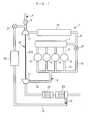
FIG. 1 is a schematic diagram of an internal combustion engine to which is applied the present invention; -
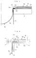
FIG. 2 is an enlarged view of a portion of theFIG. 1 engine, where a filter is mounted; -
FIG. 3 is a further enlarged view of a filter mounting structure; -
FIG. 4 is a further enlarged view of a part ofFIG. 3 , in a state where a gasket is crushed; -
FIG. 5 is a view similar toFIG. 4 , which shows a variation of the filter mounting structure; and -
FIG. 6 is a view similar toFIG. 3 , which shows a conventional filter mounting structure. - The present invention will now be described in detail with reference to the drawings showing preferred embodiments thereof. As shown in
FIG. 1 , an internal combustion engine (hereinafter referred to as the "engine") 1 is a diesel engine for a vehicle (not shown), which has fourcylinders 3. - Intake piping 4 and exhaust piping 5 are connected to the
cylinders 3. The intake piping 4 comprises anintake pipe 6, and anintake manifold 8 connected to theintake pipe 6 via anintake chamber 7. Theintake manifold 8 is connected to thecylinders 3. - The
intake pipe 6 is provided with athrottle valve 9, acompressor 11 of aturbocharger 10, and anintercooler 12, at respective locations from upstream to downstream in the mentioned order. Thethrottle valve 9 is actuated by an actuator (not shown), for adjustment of the amount of fresh air sucked into eachcylinder 3. Thecompressor 11 is driven by aturbine 21, referred to hereinafter, for supercharging intake air. Further, theintercooler 12 cools the intake air the temperature of which has been raised by the supercharging operation of thecompressor 11. - On the other hand, the exhaust piping 5 comprises an
exhaust manifold 13 connected to eachcylinder 3, anexhaust pipe 14 connected to the downstream side of theexhaust manifold 13, and a high-pressure EGR pipe 15 and a low-pressure EGR pipe 16 which are connected in parallel with each other between theexhaust pipe 14 and theintake pipe 6. - The
exhaust pipe 14 is provided with theturbine 21 of theturbocharger 10, aNOx catalyst 22, and a DPF (Diesel Particulate Filter) 23, at respective locations from upstream to downstream in the mentioned order. Theturbine 21 is driven by exhaust gases flowing through theexhaust pipe 14, for causing thecompressor 11 to rotate in unison via aturbine shaft 21a such that thecompressor 11 performs the supercharging operation. - The
NOx catalyst 22 carries a zeolite or the like thereon. TheNOx catalyst 22 traps NOx contained in exhaust gases during the lean operation of the engine 1, and releases the trapped NOx in the reduced state by being supplied with reducing agent e.g. during the rich operation of the engine 1, to thereby purify the exhaust gases. Further, theDPF 23 comprises a ceramic, and purifies the exhaust gases by collecting particulates, such as soot, from exhaust gases. - Further, the high-
pressure EGR pipe 15 branches from a portion of theexhaust pipe 14 upstream of theturbine 21, and joins a portion of theintake pipe 6 downstream of theintercooler 12. This recirculates high-temperature, high-pressure exhaust gases into theintake pipe 6 as high-pressure EGR gas via the high-pressure EGR pipe 15. The high-pressure EGR pipe 15 is provided with a high-pressureEGR control valve 24 for controlling the amount of high-pressure EGR gas. - On the other hand, the low-
pressure EGR pipe 16 branches from a portion of theexhaust pipe 14 downstream of theDPF 23, and joins a portion of theintake pipe 6 upstream of thecompressor 11. This recirculates lower-temperature, lower-pressure exhaust gases than the high-pressure EGR gas as low-pressure EGR gas into theintake pipe 6 via the low-pressure EGR pipe 16. - Further, the low-
pressure EGR pipe 16 is provided with afilter 25 for trapping foreign matter contained in the low-pressure EGR gas, anEGR cooler 26 for cooling the low-pressure EGR gas, and a low-pressureEGR control valve 27 for controlling the amount of the low-pressure EGR gas, from upstream to downstream of exhaust gases (from theDPF 23 toward the intake pipe 6) in the mentioned order. The foreign matter in the low-pressure EGR gas includes not only oxides generated on the downstream side of theDPF 23 but also ceramic pieces dropped off theDPF 23, etc. - Next, the construction of the
filter 25 and a mounting structure for thefilter 25 will be described with reference toFIGS. 2 to 4 . Thefilter 25 is a metal mesh filter having shape retainability, and comprises afilter body 25a having a hemispherical shape, and a brim-shaped mountingportion 25b extending continuous with thefilter body 25a circumferentially along the outer periphery thereof. - The
filter 25 is mounted on a portion where a connectingpipe 28 that protrudes from acasing 23a accommodating theDPF 23 and the low-pressure EGR pipe 16 are connected, in a state where thefilter body 25a blocks a passage extending through the low-pressure EGR pipe 16 with an opening of thefilter body 25a facing upstream. Thefilter 25 is mounted using a pair offlanges gasket 32 and aframe 33. - Each
flange 31 is formed e.g. by a steel plate, and has a relatively thick annular plate-shape. The pair offlanges pressure EGR pipe 16 and the connectingpipe 28, and are arranged in a manner opposed to each other. Theflanges fastening tools 34, such as bolts and nuts. - The
gasket 32 also has an annular plate-shape, and is sandwiched between the fastenedflanges gasket 32 is formed by partially joining and laminating fivesheets 32a made e.g. of stainless steel plates. Out of five layers of thesheets 32a, three layers except the top and bottom layers are arranged in a manner spaced outward from an outer peripheral surface of the low-pressure EGR pipe 16. On the other hand, the top and bottom layers extend in a manner overlapping the three layers, and further inward beyond the inner ends of the three layers to the vicinity of the outer peripheral surface of the low-pressure EGR pipe 16. - With the above arrangement, a sealing
portion 32b is formed by an outer part of thegasket 32 made of the fivesheet 32a overlapping each other. Further, the top andbottom layers portion 32b correspond to upstream-side and downstream-side extending portions portion 32d. - The
frame 33 is made e.g. of a stainless steel plate, and is mounted on a part of thefilter 25 from a base portion of thefilter body 25a to the mountingportion 25b along the whole length of thefilter 25 in the circumferential direction. Further, the extreme end of theframe 33 is folded back into two so as to cover the mountingportion 25b of thefilter 25 from opposite sides. - Now, the thicknesses of the above-described component elements are collectively shown. The thickness t1 of the
filter 25 is set to 0.3 mm, the thickness t2 of eachsheet 32a of thegasket 32 is set to 0.3 mm, and the thickness t3 of theframe 33 is set to 0.2 mm, for example. - The mounting of the
filter 25 using these component elements is carried out, for example, as follows: First, as shown inFIG. 3 , thegasket 32 is placed on theflange 31 provided on an end of the low-pressure EGR pipe 16. Next, the mountingportion 25b of thefilter 25 having theframe 33 attached thereto is engaged between the extendingportions portion 32d of thegasket 32. Then, the end of the low-pressure EGR pipe 16 is aligned with an end of the connectingpipe 28, and theflanges fastening tools 34, whereby the assembly of the component elements and the mounting of thefilter 25 are completed. - In the state where the
filter 25 is mounted as described above, the sealingportion 32b of thegasket 32 is crushed by fastening theflanges portion 25b of thefilter 25 is sealed. Further, the holdingportion 32d of thegasket 32 holds thefilter 25 with the mountingportion 25b of thefilter 25 engaged therewith. - Further, since the thickness t1 of the
filter 25, the thickness t2 of eachsheet 32a of thegasket 32, and the thickness t3 of theframe 33 are set as described above, the thickness ts (= 5 x t2) of the sealingportion 32b is larger than the total thickness th (= t1 + 2 x t2 + 2 x t3) of the holdingportion 32d. Because of this relationship, even when the sealingportion 32b is crushed as described above, the holdingportion 32d is not crushed, whereby a gap G approximately equal to the difference between the thicknesses (= ts - th) is formed between the upstream-side extending portion 32c and thefilter 25. - As described hereinabove, according to the mounting structure for the
filter 25 of the present embodiment, the sealingportion 32b of thegasket 32 disposed outward of the exhaust piping in a manner spaced therefrom is sandwiched between theflanges filter 25 in the crushed state. Further, the holdingportion 32d of thegasket 32 disposed in the vicinity of the exhaust piping holds thefilter 25 with the mountingportion 25b of thefilter 25 engaged therewith. - Further, the thickness ts of the sealing
portion 32b of thegasket 32 is set to be larger than the total thickness th of the holdingportion 32d, which is the sum of the thicknesses of thefilter 25, the holdingportion 32d and theframe 33, and hence even in the state where the sealingportion 32b of thegasket 32 is crushed, portions of theflanges 31 corresponding to the holdingportion 32d are not deformed. This makes it possible to improve the sealing property of the holdingportion 32d to positively prevent exhaust gases from leaking from the holdingportion 32d. Further, the basic construction that thefilter 25 is mounted by sandwiching thegasket 32 between the pair offlanges - Further, the mounting
portion 25b of thefilter 25 formed by a mesh filter is covered by theframe 33, and is engaged with the holdingportion 32d of thegasket 32 via theframe 33. This makes it possible to prevent metal wires from dropping off thefilter 25, thereby making it possible to maintain an excellent sealing property. - Furthermore, the
filter 25 is mounted on the low-pressure EGR pipe 16 that branches from the portion of theexhaust pipe 14 downstream of theDPF 23 and joins the portion of theintake pipe 6 upstream of thecompressor 11 of theturbocharger 10. This makes it possible to trap oxides generated downstream of theDPF 23, ceramic pieces dropped off theDPF 23, and so forth, in thefilter 25, so that it is possible to positively prevent these pieces of foreign matter from flowing into thecompressor 11, and prevent damage or breakage of thecompressor 11 from occurring due to the foreign matter flowing into thecompressor 11. - Next, a variation of the mounting structure for the
filter 25 will be described with reference toFIG. 5 . As shown inFIG. 5 , in this variation, the upstream-side extending portion 32c of the holdingportion 32d of thegasket 32 has acover portion 32e formed in a manner inclined toward the downstream side of exhaust gases. The remainder of the construction of the variation is the same as that of the above-described embodiment. - According to the above variation, the gap G between the upstream-
side extending portion 32c of thegasket 32 and theframe 33 enclosing the mountingportion 25b of thefilter 25 is covered by thecover portion 32e, it is possible to prevent foreign matter from flowing into the gap G, and therefore, it is possible to maintain an excellent sealing property. - It should be noted that the present invention is by no means limited to the embodiment described above, but can be practiced in various forms. For example, although in the above-described embodiment, to prevent the portions of the
flanges 31 corresponding to the holdingportion 32d from being deformed even in the state where the sealingportion 32b of thegasket 32 is crushed, the thickness ts of the sealingportion 32b is set to a larger value than that of the total thickness th of the holdingportion 32d, the thickness ts of the sealingportion 32b may be set to the same value as that of the total thickness th. In this case as well, it is possible to obtain the same advantageous effects described above. - Further, although in the above-described embodiment, to protect the
filter 25, theframe 33 is provided on the mountingportion 25b of thefilter 25, theframe 33 may be omitted. In this case, the thickness ts of the sealingportion 32b is set to be not smaller than the total thickness th of the holdingportion 32d (the sum of the thicknesses of thefilter 25 and the holdingportion 32d). - Furthermore, although in the above-described embodiment, the
filter 25 is mounted on the low-pressure EGR pipe 16, thefilter 25 may be mounted on another suitable portion of the exhaust piping 5, such as the high-pressure EGR pipe 15. Further, although in the above-described embodiment, theflange 31 toward theDPF 23 is formed on the connectingpipe 28 protruding from thecasing 23a, it may be directly formed on thecasing 23a. Furthermore, although in the above-described embodiment, thegasket 32 is formed by the plurality oflaminated sheets 32a, thegasket 32 may be integrally formed such that it includes a sealing portion and a holding portions which satisfy the requirements of the present invention. - Further, although in the above-described embodiment, the present invention is applied to the diesel engine installed on an automotive vehicle by way of example, this is not limitative, but it can be applied to various types of engines, such as gasoline engines, and engines for other than automotive vehicles, such as engines for ship propulsion machines, e.g. an outboard motor having a vertically-disposed crankshaft.
- It is further understood by those skilled in the art that the foregoing are preferred embodiments of the invention, and that various changes and modifications may be made without departing from the spirit and scope thereof.
- A filter mounting structure for an internal combustion engine, capable of preventing deformation of flanges when mounting a filter on exhaust piping, thereby improving the sealing property of a filter-mounted portion and positively preventing leakage of exhaust gases, while maintaining a simple construction. In the filter mounting structure, a pair of flanges are provided on a low-pressure EGR pipe and a connecting pipe, respectively. A gasket is sandwiched between the flanges. The gasket has a sealing portion for sealing exhaust gases, disposed outward of the outer peripheral surface of the low-pressure EGR pipe in a manner spaced therefrom and sandwiched between the flanges, and a holding portion for holding the filter, engaged with the filter mounting portion and disposed inward of the sealing portion. The thickness of the sealing portion is set to be not smaller than the total thickness of the filter and the holding portion.
Claims (4)
- A filter mounting structure for an internal combustion engine, for mounting, on exhaust piping (16) through which flow exhaust gases discharged from the engine (1), a metal filter (25) for removing foreign matter from the exhaust gases, including:a pair of flanges (31, 31) provided on an end of the exhaust piping and a piping member (28) to which the end of the exhaust piping is connected, respectively, in a manner opposed to each other; anda gasket (32) sandwiched between said pair of flanges (31, 31),characterized in that said gasket (32) comprises:a sealing portion (32b) that is disposed outward of an outer peripheral surface of the exhaust piping in a manner spaced therefrom and is sandwiched between said pair of flanges (31, 31), for sealing exhaust gases; anda holding portion (32d) that extends inwardly from said sealing portion (32b) to a vicinity of the outer peripheral surface of the exhaust piping and holds said filter (25) in a state where an outer peripheral portion (25b) of said filter (25) is engaged with said holding portion (32d),wherein a thickness (ts) of said sealing portion (32b) of said gasket (32) is set to be not smaller than a total thickness (th) of said holding portion, which is a sum of respective thicknesses of said filter (25) and said holding portion (32d).
- The filter mounting structure as claimed in claim 1, wherein said filter (25) is a metal mesh filter,
the filter mounting structure further comprising a frame (33) that is mounted on an outer peripheral portion of said mesh filter in a manner covering the outer peripheral portion and is engaged with said holding portion (32d) of said gasket (32),
wherein the thickness (ts) of said sealing portion (32b) of said gasket (32) is set to be not smaller than the total thickness (th) of said holding portion, which is a sum of respective thicknesses of said filter (25), said holding portion (32d), and said frame (33). - The filter mounting structure as claimed in claim 1 or 2, wherein said holding portion (32d) of said gasket (32) includes upstream-side and downstream-side extending portions (32c, 32c) extending inwardly from said sealing portion (32b) in a state spaced from each other in a direction of flow of exhaust gases, said outer peripheral portion of said filter (25) being engaged between said upstream-side and downstream-side extending portions (32c, 32c),
wherein the thickness (ts) of said sealing portion (32b) of said gasket (32) is set to be larger than the total thickness (th) of said holding portion, and
wherein said upstream-side extending portion (32c) of said holding portion (32d) has a cover portion (32e) formed in a manner inclined toward a downstream side of exhaust gases such that said cover portion (32e) covers a gap (G) between said upstream-side extending portion (32c) and said filter (25). - The filter mounting structure as claimed in any one of claims 1 to 3, wherein the exhaust piping is provided with a turbine (21) for a supercharger (10) for driving a compressor (11) for the supercharger (10), the compressor (11) being disposed in intake piping (6) for sucking fresh air into the engine (1),
a purifying device (23) for purifying exhaust gases, and
an exhaust gas recirculation pipe (16) that branches from a portion of the exhaust piping downstream of said purifying device and joins a portion of the intake piping upstream of the compressor (11), for recirculating part of exhaust gases into the intake piping, and
wherein said filter (25) is mounted on said exhaust gas recirculation pipe.
Applications Claiming Priority (1)
| Application Number | Priority Date | Filing Date | Title |
|---|---|---|---|
| JP2010068502A JP5535715B2 (en) | 2010-03-24 | 2010-03-24 | Internal combustion engine filter mounting structure |
Publications (2)
| Publication Number | Publication Date |
|---|---|
| EP2369147A1 true EP2369147A1 (en) | 2011-09-28 |
| EP2369147B1 EP2369147B1 (en) | 2013-03-06 |
Family
ID=43859248
Family Applications (1)
| Application Number | Title | Priority Date | Filing Date |
|---|---|---|---|
| EP11150990A Not-in-force EP2369147B1 (en) | 2010-03-24 | 2011-01-14 | Filter mounting structure for internal combustion engine |
Country Status (2)
| Country | Link |
|---|---|
| EP (1) | EP2369147B1 (en) |
| JP (1) | JP5535715B2 (en) |
Cited By (5)
| Publication number | Priority date | Publication date | Assignee | Title |
|---|---|---|---|---|
| CN105473909A (en) * | 2013-08-01 | 2016-04-06 | 爱尔铃克铃尔股份公司 | EGR seal with a sieve insert and manufacturing method |
| CN111156112A (en) * | 2020-01-17 | 2020-05-15 | 温州盛广机电有限公司 | EGR valve assembly |
| CN112752896A (en) * | 2018-10-09 | 2021-05-04 | 沃尔沃卡车集团 | Exhaust gas aftertreatment device for an exhaust gas system of an internal combustion engine |
| CN113339104A (en) * | 2020-02-18 | 2021-09-03 | 马勒国际有限公司 | Filter device |
| US20210370207A1 (en) * | 2020-05-27 | 2021-12-02 | Hyundai Motor Company | EM Filter for EGR Cooler |
Families Citing this family (4)
| Publication number | Priority date | Publication date | Assignee | Title |
|---|---|---|---|---|
| JP5924688B2 (en) | 2012-10-29 | 2016-05-25 | 本田技研工業株式会社 | Exhaust gas recirculation device for internal combustion engine |
| JP2015055189A (en) * | 2013-09-12 | 2015-03-23 | マルヤス工業株式会社 | Filter mounting structure of internal combustion engine |
| JP6588208B2 (en) * | 2015-01-06 | 2019-10-09 | フタバ産業株式会社 | Manufacturing method of EGR pipe with filter and EGR pipe |
| KR101993165B1 (en) * | 2017-09-14 | 2019-07-09 | 동아공업 주식회사 | Filtering assembly structure of exhaust gas recirculation system |
Citations (5)
| Publication number | Priority date | Publication date | Assignee | Title |
|---|---|---|---|---|
| US5027781A (en) * | 1990-03-28 | 1991-07-02 | Lewis Calvin C | EGR valve carbon control screen and gasket |
| JPH0771329A (en) | 1993-09-01 | 1995-03-14 | Hino Motors Ltd | Exhaust gas recirculation device of engine with supercharger |
| WO1998012424A1 (en) * | 1996-09-19 | 1998-03-26 | Precision Combustion Inc. | Catalyst protection filter |
| JP2002364333A (en) * | 2001-06-05 | 2002-12-18 | Toyota Motor Corp | Exhaust gas purification device |
| US20070151231A1 (en) * | 2005-12-29 | 2007-07-05 | Rinaldi Fabrizio C | Woven metal fiber diesel particulate filter |
Family Cites Families (4)
| Publication number | Priority date | Publication date | Assignee | Title |
|---|---|---|---|---|
| JPS5898651A (en) * | 1981-12-08 | 1983-06-11 | Ngk Spark Plug Co Ltd | Exhaust-gas purifying apparatus for diesel engine |
| JPH11350368A (en) * | 1998-06-09 | 1999-12-21 | Yokogawa Electric Corp | White liquor continuous measurement device |
| JP2004340253A (en) * | 2003-05-15 | 2004-12-02 | Tlv Co Ltd | Temporary strainer |
| JPWO2007034675A1 (en) * | 2005-09-26 | 2009-03-19 | 三桜工業株式会社 | EGR pipe |
-
2010
- 2010-03-24 JP JP2010068502A patent/JP5535715B2/en not_active Expired - Fee Related
-
2011
- 2011-01-14 EP EP11150990A patent/EP2369147B1/en not_active Not-in-force
Patent Citations (5)
| Publication number | Priority date | Publication date | Assignee | Title |
|---|---|---|---|---|
| US5027781A (en) * | 1990-03-28 | 1991-07-02 | Lewis Calvin C | EGR valve carbon control screen and gasket |
| JPH0771329A (en) | 1993-09-01 | 1995-03-14 | Hino Motors Ltd | Exhaust gas recirculation device of engine with supercharger |
| WO1998012424A1 (en) * | 1996-09-19 | 1998-03-26 | Precision Combustion Inc. | Catalyst protection filter |
| JP2002364333A (en) * | 2001-06-05 | 2002-12-18 | Toyota Motor Corp | Exhaust gas purification device |
| US20070151231A1 (en) * | 2005-12-29 | 2007-07-05 | Rinaldi Fabrizio C | Woven metal fiber diesel particulate filter |
Cited By (8)
| Publication number | Priority date | Publication date | Assignee | Title |
|---|---|---|---|---|
| CN105473909A (en) * | 2013-08-01 | 2016-04-06 | 爱尔铃克铃尔股份公司 | EGR seal with a sieve insert and manufacturing method |
| CN112752896A (en) * | 2018-10-09 | 2021-05-04 | 沃尔沃卡车集团 | Exhaust gas aftertreatment device for an exhaust gas system of an internal combustion engine |
| US11555435B2 (en) | 2018-10-09 | 2023-01-17 | Volvo Truck Corporation | Exhaust aftertreatment unit for an exhaust system of an internal combustion engine |
| CN112752896B (en) * | 2018-10-09 | 2024-02-06 | 沃尔沃卡车集团 | Exhaust gas aftertreatment device for an exhaust system of an internal combustion engine |
| CN111156112A (en) * | 2020-01-17 | 2020-05-15 | 温州盛广机电有限公司 | EGR valve assembly |
| CN113339104A (en) * | 2020-02-18 | 2021-09-03 | 马勒国际有限公司 | Filter device |
| US20210370207A1 (en) * | 2020-05-27 | 2021-12-02 | Hyundai Motor Company | EM Filter for EGR Cooler |
| US11779868B2 (en) * | 2020-05-27 | 2023-10-10 | Hyundai Motor Company | EM filter for EGR cooler |
Also Published As
| Publication number | Publication date |
|---|---|
| EP2369147B1 (en) | 2013-03-06 |
| JP2011202536A (en) | 2011-10-13 |
| JP5535715B2 (en) | 2014-07-02 |
Similar Documents
| Publication | Publication Date | Title |
|---|---|---|
| EP2369147B1 (en) | Filter mounting structure for internal combustion engine | |
| CN102472134B (en) | Exhaust gas purification device | |
| JP5136654B2 (en) | Control device for internal combustion engine | |
| US20140366533A1 (en) | Supercharger-equipped internal combustion engine | |
| EP1770270A3 (en) | EGR system having reverse flow, internal combustion engine and method | |
| US8950179B2 (en) | Engine exhaust aftertreatment component including aftertreatment brick module | |
| JP2012149558A (en) | Exhaust gas recirculation system of internal combustion engine | |
| US12203430B2 (en) | Engine | |
| KR101968369B1 (en) | Exhaust gas purifier | |
| US20150240751A1 (en) | Intake and exhaust system for internal combustion engine | |
| JP2016094888A (en) | Blowby gas recirculation system | |
| JP7095234B2 (en) | Exhaust gas recirculation device | |
| JP5786662B2 (en) | Exhaust device for internal combustion engine | |
| CN105452745A (en) | High temperature valve shaft seal | |
| JP7102747B2 (en) | Engine exhaust purification device | |
| JP5168268B2 (en) | Exhaust gas recirculation device for internal combustion engine | |
| JP2010223077A (en) | Internal combustion engine | |
| JP7206945B2 (en) | internal combustion engine for vehicle | |
| JP4710725B2 (en) | Turbocharged engine | |
| JP2010190176A (en) | Abnormality determination device for internal combustion engine | |
| JP7234649B2 (en) | internal combustion engine for vehicle | |
| JP5262992B2 (en) | Control device for internal combustion engine | |
| JP2015055189A (en) | Filter mounting structure of internal combustion engine | |
| JP2009091905A (en) | Exhaust gas purification device for internal combustion engine | |
| EP2105596A3 (en) | Pre-turbine exhaust filtration system for internal combustion engines |
Legal Events
| Date | Code | Title | Description |
|---|---|---|---|
| PUAI | Public reference made under article 153(3) epc to a published international application that has entered the european phase |
Free format text: ORIGINAL CODE: 0009012 |
|
| 17P | Request for examination filed |
Effective date: 20110114 |
|
| AK | Designated contracting states |
Kind code of ref document: A1 Designated state(s): AL AT BE BG CH CY CZ DE DK EE ES FI FR GB GR HR HU IE IS IT LI LT LU LV MC MK MT NL NO PL PT RO RS SE SI SK SM TR |
|
| AX | Request for extension of the european patent |
Extension state: BA ME |
|
| GRAP | Despatch of communication of intention to grant a patent |
Free format text: ORIGINAL CODE: EPIDOSNIGR1 |
|
| RIC1 | Information provided on ipc code assigned before grant |
Ipc: F01N 3/021 20060101AFI20120823BHEP Ipc: F02M 25/07 20060101ALI20120823BHEP Ipc: F01N 3/022 20060101ALI20120823BHEP Ipc: F01N 13/18 20100101ALI20120823BHEP |
|
| GRAS | Grant fee paid |
Free format text: ORIGINAL CODE: EPIDOSNIGR3 |
|
| GRAA | (expected) grant |
Free format text: ORIGINAL CODE: 0009210 |
|
| AK | Designated contracting states |
Kind code of ref document: B1 Designated state(s): AL AT BE BG CH CY CZ DE DK EE ES FI FR GB GR HR HU IE IS IT LI LT LU LV MC MK MT NL NO PL PT RO RS SE SI SK SM TR |
|
| REG | Reference to a national code |
Ref country code: GB Ref legal event code: FG4D |
|
| REG | Reference to a national code |
Ref country code: AT Ref legal event code: REF Ref document number: 599750 Country of ref document: AT Kind code of ref document: T Effective date: 20130315 Ref country code: CH Ref legal event code: EP |
|
| REG | Reference to a national code |
Ref country code: IE Ref legal event code: FG4D |
|
| REG | Reference to a national code |
Ref country code: DE Ref legal event code: R096 Ref document number: 602011000944 Country of ref document: DE Effective date: 20130502 |
|
| REG | Reference to a national code |
Ref country code: AT Ref legal event code: MK05 Ref document number: 599750 Country of ref document: AT Kind code of ref document: T Effective date: 20130306 |
|
| PG25 | Lapsed in a contracting state [announced via postgrant information from national office to epo] |
Ref country code: BG Free format text: LAPSE BECAUSE OF FAILURE TO SUBMIT A TRANSLATION OF THE DESCRIPTION OR TO PAY THE FEE WITHIN THE PRESCRIBED TIME-LIMIT Effective date: 20130606 Ref country code: LT Free format text: LAPSE BECAUSE OF FAILURE TO SUBMIT A TRANSLATION OF THE DESCRIPTION OR TO PAY THE FEE WITHIN THE PRESCRIBED TIME-LIMIT Effective date: 20130306 Ref country code: NO Free format text: LAPSE BECAUSE OF FAILURE TO SUBMIT A TRANSLATION OF THE DESCRIPTION OR TO PAY THE FEE WITHIN THE PRESCRIBED TIME-LIMIT Effective date: 20130606 Ref country code: SE Free format text: LAPSE BECAUSE OF FAILURE TO SUBMIT A TRANSLATION OF THE DESCRIPTION OR TO PAY THE FEE WITHIN THE PRESCRIBED TIME-LIMIT Effective date: 20130306 Ref country code: ES Free format text: LAPSE BECAUSE OF FAILURE TO SUBMIT A TRANSLATION OF THE DESCRIPTION OR TO PAY THE FEE WITHIN THE PRESCRIBED TIME-LIMIT Effective date: 20130617 Ref country code: AT Free format text: LAPSE BECAUSE OF FAILURE TO SUBMIT A TRANSLATION OF THE DESCRIPTION OR TO PAY THE FEE WITHIN THE PRESCRIBED TIME-LIMIT Effective date: 20130306 |
|
| REG | Reference to a national code |
Ref country code: NL Ref legal event code: VDEP Effective date: 20130306 |
|
| REG | Reference to a national code |
Ref country code: LT Ref legal event code: MG4D |
|
| PG25 | Lapsed in a contracting state [announced via postgrant information from national office to epo] |
Ref country code: FI Free format text: LAPSE BECAUSE OF FAILURE TO SUBMIT A TRANSLATION OF THE DESCRIPTION OR TO PAY THE FEE WITHIN THE PRESCRIBED TIME-LIMIT Effective date: 20130306 Ref country code: SI Free format text: LAPSE BECAUSE OF FAILURE TO SUBMIT A TRANSLATION OF THE DESCRIPTION OR TO PAY THE FEE WITHIN THE PRESCRIBED TIME-LIMIT Effective date: 20130306 Ref country code: LV Free format text: LAPSE BECAUSE OF FAILURE TO SUBMIT A TRANSLATION OF THE DESCRIPTION OR TO PAY THE FEE WITHIN THE PRESCRIBED TIME-LIMIT Effective date: 20130306 Ref country code: GR Free format text: LAPSE BECAUSE OF FAILURE TO SUBMIT A TRANSLATION OF THE DESCRIPTION OR TO PAY THE FEE WITHIN THE PRESCRIBED TIME-LIMIT Effective date: 20130607 |
|
| PG25 | Lapsed in a contracting state [announced via postgrant information from national office to epo] |
Ref country code: RS Free format text: LAPSE BECAUSE OF FAILURE TO SUBMIT A TRANSLATION OF THE DESCRIPTION OR TO PAY THE FEE WITHIN THE PRESCRIBED TIME-LIMIT Effective date: 20130306 Ref country code: BE Free format text: LAPSE BECAUSE OF FAILURE TO SUBMIT A TRANSLATION OF THE DESCRIPTION OR TO PAY THE FEE WITHIN THE PRESCRIBED TIME-LIMIT Effective date: 20130306 Ref country code: HR Free format text: LAPSE BECAUSE OF FAILURE TO SUBMIT A TRANSLATION OF THE DESCRIPTION OR TO PAY THE FEE WITHIN THE PRESCRIBED TIME-LIMIT Effective date: 20130306 |
|
| PG25 | Lapsed in a contracting state [announced via postgrant information from national office to epo] |
Ref country code: EE Free format text: LAPSE BECAUSE OF FAILURE TO SUBMIT A TRANSLATION OF THE DESCRIPTION OR TO PAY THE FEE WITHIN THE PRESCRIBED TIME-LIMIT Effective date: 20130306 Ref country code: SK Free format text: LAPSE BECAUSE OF FAILURE TO SUBMIT A TRANSLATION OF THE DESCRIPTION OR TO PAY THE FEE WITHIN THE PRESCRIBED TIME-LIMIT Effective date: 20130306 Ref country code: CZ Free format text: LAPSE BECAUSE OF FAILURE TO SUBMIT A TRANSLATION OF THE DESCRIPTION OR TO PAY THE FEE WITHIN THE PRESCRIBED TIME-LIMIT Effective date: 20130306 Ref country code: PT Free format text: LAPSE BECAUSE OF FAILURE TO SUBMIT A TRANSLATION OF THE DESCRIPTION OR TO PAY THE FEE WITHIN THE PRESCRIBED TIME-LIMIT Effective date: 20130708 Ref country code: NL Free format text: LAPSE BECAUSE OF FAILURE TO SUBMIT A TRANSLATION OF THE DESCRIPTION OR TO PAY THE FEE WITHIN THE PRESCRIBED TIME-LIMIT Effective date: 20130306 Ref country code: IS Free format text: LAPSE BECAUSE OF FAILURE TO SUBMIT A TRANSLATION OF THE DESCRIPTION OR TO PAY THE FEE WITHIN THE PRESCRIBED TIME-LIMIT Effective date: 20130706 Ref country code: RO Free format text: LAPSE BECAUSE OF FAILURE TO SUBMIT A TRANSLATION OF THE DESCRIPTION OR TO PAY THE FEE WITHIN THE PRESCRIBED TIME-LIMIT Effective date: 20130306 |
|
| PG25 | Lapsed in a contracting state [announced via postgrant information from national office to epo] |
Ref country code: PL Free format text: LAPSE BECAUSE OF FAILURE TO SUBMIT A TRANSLATION OF THE DESCRIPTION OR TO PAY THE FEE WITHIN THE PRESCRIBED TIME-LIMIT Effective date: 20130306 |
|
| PLBE | No opposition filed within time limit |
Free format text: ORIGINAL CODE: 0009261 |
|
| STAA | Information on the status of an ep patent application or granted ep patent |
Free format text: STATUS: NO OPPOSITION FILED WITHIN TIME LIMIT |
|
| PG25 | Lapsed in a contracting state [announced via postgrant information from national office to epo] |
Ref country code: DK Free format text: LAPSE BECAUSE OF FAILURE TO SUBMIT A TRANSLATION OF THE DESCRIPTION OR TO PAY THE FEE WITHIN THE PRESCRIBED TIME-LIMIT Effective date: 20130306 |
|
| 26N | No opposition filed |
Effective date: 20131209 |
|
| PG25 | Lapsed in a contracting state [announced via postgrant information from national office to epo] |
Ref country code: IT Free format text: LAPSE BECAUSE OF FAILURE TO SUBMIT A TRANSLATION OF THE DESCRIPTION OR TO PAY THE FEE WITHIN THE PRESCRIBED TIME-LIMIT Effective date: 20130306 |
|
| REG | Reference to a national code |
Ref country code: DE Ref legal event code: R097 Ref document number: 602011000944 Country of ref document: DE Effective date: 20131209 |
|
| PG25 | Lapsed in a contracting state [announced via postgrant information from national office to epo] |
Ref country code: LU Free format text: LAPSE BECAUSE OF FAILURE TO SUBMIT A TRANSLATION OF THE DESCRIPTION OR TO PAY THE FEE WITHIN THE PRESCRIBED TIME-LIMIT Effective date: 20140114 |
|
| REG | Reference to a national code |
Ref country code: CH Ref legal event code: PL |
|
| PG25 | Lapsed in a contracting state [announced via postgrant information from national office to epo] |
Ref country code: CH Free format text: LAPSE BECAUSE OF NON-PAYMENT OF DUE FEES Effective date: 20140131 Ref country code: LI Free format text: LAPSE BECAUSE OF NON-PAYMENT OF DUE FEES Effective date: 20140131 |
|
| REG | Reference to a national code |
Ref country code: FR Ref legal event code: ST Effective date: 20140930 |
|
| REG | Reference to a national code |
Ref country code: IE Ref legal event code: MM4A |
|
| REG | Reference to a national code |
Ref country code: DE Ref legal event code: R084 Ref document number: 602011000944 Country of ref document: DE |
|
| PG25 | Lapsed in a contracting state [announced via postgrant information from national office to epo] |
Ref country code: FR Free format text: LAPSE BECAUSE OF NON-PAYMENT OF DUE FEES Effective date: 20140131 |
|
| REG | Reference to a national code |
Ref country code: DE Ref legal event code: R084 Ref document number: 602011000944 Country of ref document: DE Effective date: 20141120 |
|
| PG25 | Lapsed in a contracting state [announced via postgrant information from national office to epo] |
Ref country code: IE Free format text: LAPSE BECAUSE OF NON-PAYMENT OF DUE FEES Effective date: 20140114 |
|
| PG25 | Lapsed in a contracting state [announced via postgrant information from national office to epo] |
Ref country code: MC Free format text: LAPSE BECAUSE OF FAILURE TO SUBMIT A TRANSLATION OF THE DESCRIPTION OR TO PAY THE FEE WITHIN THE PRESCRIBED TIME-LIMIT Effective date: 20130306 |
|
| GBPC | Gb: european patent ceased through non-payment of renewal fee |
Effective date: 20150114 |
|
| PG25 | Lapsed in a contracting state [announced via postgrant information from national office to epo] |
Ref country code: GB Free format text: LAPSE BECAUSE OF NON-PAYMENT OF DUE FEES Effective date: 20150114 |
|
| PG25 | Lapsed in a contracting state [announced via postgrant information from national office to epo] |
Ref country code: MT Free format text: LAPSE BECAUSE OF FAILURE TO SUBMIT A TRANSLATION OF THE DESCRIPTION OR TO PAY THE FEE WITHIN THE PRESCRIBED TIME-LIMIT Effective date: 20130306 |
|
| PG25 | Lapsed in a contracting state [announced via postgrant information from national office to epo] |
Ref country code: SM Free format text: LAPSE BECAUSE OF FAILURE TO SUBMIT A TRANSLATION OF THE DESCRIPTION OR TO PAY THE FEE WITHIN THE PRESCRIBED TIME-LIMIT Effective date: 20130306 |
|
| PG25 | Lapsed in a contracting state [announced via postgrant information from national office to epo] |
Ref country code: CY Free format text: LAPSE BECAUSE OF FAILURE TO SUBMIT A TRANSLATION OF THE DESCRIPTION OR TO PAY THE FEE WITHIN THE PRESCRIBED TIME-LIMIT Effective date: 20130306 |
|
| PG25 | Lapsed in a contracting state [announced via postgrant information from national office to epo] |
Ref country code: TR Free format text: LAPSE BECAUSE OF FAILURE TO SUBMIT A TRANSLATION OF THE DESCRIPTION OR TO PAY THE FEE WITHIN THE PRESCRIBED TIME-LIMIT Effective date: 20130306 Ref country code: HU Free format text: LAPSE BECAUSE OF FAILURE TO SUBMIT A TRANSLATION OF THE DESCRIPTION OR TO PAY THE FEE WITHIN THE PRESCRIBED TIME-LIMIT; INVALID AB INITIO Effective date: 20110114 |
|
| PGFP | Annual fee paid to national office [announced via postgrant information from national office to epo] |
Ref country code: DE Payment date: 20180103 Year of fee payment: 8 |
|
| PG25 | Lapsed in a contracting state [announced via postgrant information from national office to epo] |
Ref country code: MK Free format text: LAPSE BECAUSE OF FAILURE TO SUBMIT A TRANSLATION OF THE DESCRIPTION OR TO PAY THE FEE WITHIN THE PRESCRIBED TIME-LIMIT Effective date: 20130306 |
|
| PG25 | Lapsed in a contracting state [announced via postgrant information from national office to epo] |
Ref country code: AL Free format text: LAPSE BECAUSE OF FAILURE TO SUBMIT A TRANSLATION OF THE DESCRIPTION OR TO PAY THE FEE WITHIN THE PRESCRIBED TIME-LIMIT Effective date: 20130306 |
|
| REG | Reference to a national code |
Ref country code: DE Ref legal event code: R119 Ref document number: 602011000944 Country of ref document: DE |
|
| PG25 | Lapsed in a contracting state [announced via postgrant information from national office to epo] |
Ref country code: DE Free format text: LAPSE BECAUSE OF NON-PAYMENT OF DUE FEES Effective date: 20190801 |