EP2369036A1 - Coating apparatus and method - Google Patents
Coating apparatus and method Download PDFInfo
- Publication number
- EP2369036A1 EP2369036A1 EP11250293A EP11250293A EP2369036A1 EP 2369036 A1 EP2369036 A1 EP 2369036A1 EP 11250293 A EP11250293 A EP 11250293A EP 11250293 A EP11250293 A EP 11250293A EP 2369036 A1 EP2369036 A1 EP 2369036A1
- Authority
- EP
- European Patent Office
- Prior art keywords
- susceptor
- coating
- work piece
- process chamber
- electron beam
- Prior art date
- Legal status (The legal status is an assumption and is not a legal conclusion. Google has not performed a legal analysis and makes no representation as to the accuracy of the status listed.)
- Withdrawn
Links
- 238000000576 coating method Methods 0.000 title claims abstract description 89
- 239000011248 coating agent Substances 0.000 title claims abstract description 79
- 238000000034 method Methods 0.000 title claims description 53
- 239000000463 material Substances 0.000 claims abstract description 38
- 238000010894 electron beam technology Methods 0.000 claims abstract description 22
- 230000008569 process Effects 0.000 claims description 43
- 238000005086 pumping Methods 0.000 claims description 11
- 238000000151 deposition Methods 0.000 claims description 4
- 229910010293 ceramic material Inorganic materials 0.000 claims description 2
- 238000010438 heat treatment Methods 0.000 claims description 2
- 239000007921 spray Substances 0.000 claims description 2
- 238000009718 spray deposition Methods 0.000 claims 1
- 239000012720 thermal barrier coating Substances 0.000 description 17
- 238000005240 physical vapour deposition Methods 0.000 description 7
- 239000000919 ceramic Substances 0.000 description 6
- 238000011144 upstream manufacturing Methods 0.000 description 6
- 238000000926 separation method Methods 0.000 description 4
- 230000008901 benefit Effects 0.000 description 3
- 238000010276 construction Methods 0.000 description 3
- 238000001816 cooling Methods 0.000 description 3
- 230000006641 stabilisation Effects 0.000 description 3
- 238000011105 stabilization Methods 0.000 description 3
- 125000004122 cyclic group Chemical group 0.000 description 2
- 230000008021 deposition Effects 0.000 description 2
- 230000001627 detrimental effect Effects 0.000 description 2
- 230000000694 effects Effects 0.000 description 2
- 230000007613 environmental effect Effects 0.000 description 2
- 238000000605 extraction Methods 0.000 description 2
- 230000007246 mechanism Effects 0.000 description 2
- 230000009286 beneficial effect Effects 0.000 description 1
- 230000015556 catabolic process Effects 0.000 description 1
- 238000005524 ceramic coating Methods 0.000 description 1
- 238000006731 degradation reaction Methods 0.000 description 1
- 238000005137 deposition process Methods 0.000 description 1
- 230000002708 enhancing effect Effects 0.000 description 1
- 238000009413 insulation Methods 0.000 description 1
- 239000007769 metal material Substances 0.000 description 1
- 239000000203 mixture Substances 0.000 description 1
- 238000012986 modification Methods 0.000 description 1
- 230000004048 modification Effects 0.000 description 1
- 229910052574 oxide ceramic Inorganic materials 0.000 description 1
- 239000000843 powder Substances 0.000 description 1
- -1 that is Substances 0.000 description 1
- 239000012808 vapor phase Substances 0.000 description 1
- 239000002699 waste material Substances 0.000 description 1
- XLYOFNOQVPJJNP-UHFFFAOYSA-N water Substances O XLYOFNOQVPJJNP-UHFFFAOYSA-N 0.000 description 1
Images

Classifications
-
- C—CHEMISTRY; METALLURGY
- C23—COATING METALLIC MATERIAL; COATING MATERIAL WITH METALLIC MATERIAL; CHEMICAL SURFACE TREATMENT; DIFFUSION TREATMENT OF METALLIC MATERIAL; COATING BY VACUUM EVAPORATION, BY SPUTTERING, BY ION IMPLANTATION OR BY CHEMICAL VAPOUR DEPOSITION, IN GENERAL; INHIBITING CORROSION OF METALLIC MATERIAL OR INCRUSTATION IN GENERAL
- C23C—COATING METALLIC MATERIAL; COATING MATERIAL WITH METALLIC MATERIAL; SURFACE TREATMENT OF METALLIC MATERIAL BY DIFFUSION INTO THE SURFACE, BY CHEMICAL CONVERSION OR SUBSTITUTION; COATING BY VACUUM EVAPORATION, BY SPUTTERING, BY ION IMPLANTATION OR BY CHEMICAL VAPOUR DEPOSITION, IN GENERAL
- C23C14/00—Coating by vacuum evaporation, by sputtering or by ion implantation of the coating forming material
- C23C14/22—Coating by vacuum evaporation, by sputtering or by ion implantation of the coating forming material characterised by the process of coating
- C23C14/54—Controlling or regulating the coating process
- C23C14/541—Heating or cooling of the substrates
-
- C—CHEMISTRY; METALLURGY
- C23—COATING METALLIC MATERIAL; COATING MATERIAL WITH METALLIC MATERIAL; CHEMICAL SURFACE TREATMENT; DIFFUSION TREATMENT OF METALLIC MATERIAL; COATING BY VACUUM EVAPORATION, BY SPUTTERING, BY ION IMPLANTATION OR BY CHEMICAL VAPOUR DEPOSITION, IN GENERAL; INHIBITING CORROSION OF METALLIC MATERIAL OR INCRUSTATION IN GENERAL
- C23C—COATING METALLIC MATERIAL; COATING MATERIAL WITH METALLIC MATERIAL; SURFACE TREATMENT OF METALLIC MATERIAL BY DIFFUSION INTO THE SURFACE, BY CHEMICAL CONVERSION OR SUBSTITUTION; COATING BY VACUUM EVAPORATION, BY SPUTTERING, BY ION IMPLANTATION OR BY CHEMICAL VAPOUR DEPOSITION, IN GENERAL
- C23C4/00—Coating by spraying the coating material in the molten state, e.g. by flame, plasma or electric discharge
- C23C4/12—Coating by spraying the coating material in the molten state, e.g. by flame, plasma or electric discharge characterised by the method of spraying
- C23C4/137—Spraying in vacuum or in an inert atmosphere
-
- Y—GENERAL TAGGING OF NEW TECHNOLOGICAL DEVELOPMENTS; GENERAL TAGGING OF CROSS-SECTIONAL TECHNOLOGIES SPANNING OVER SEVERAL SECTIONS OF THE IPC; TECHNICAL SUBJECTS COVERED BY FORMER USPC CROSS-REFERENCE ART COLLECTIONS [XRACs] AND DIGESTS
- Y02—TECHNOLOGIES OR APPLICATIONS FOR MITIGATION OR ADAPTATION AGAINST CLIMATE CHANGE
- Y02T—CLIMATE CHANGE MITIGATION TECHNOLOGIES RELATED TO TRANSPORTATION
- Y02T50/00—Aeronautics or air transport
- Y02T50/60—Efficient propulsion technologies, e.g. for aircraft
Definitions
- the present invention relates to coating apparatuses and methods of applying coatings.
- Coatings are utilized in a variety of settings to provide a variety of benefits.
- modem gas turbine engines can include thermal barrier coatings (TBCs), environmental coatings, etc. to help promote efficient and reliable operation.
- TBCs thermal barrier coatings
- Application of coatings can involve a variety of different application methods, such as plasma-based physical vapor deposition (PVD).
- PVD plasma-based physical vapor deposition
- TBCs When TBCs are applied to gas turbine engine components, such as blades and vanes, using plasma-based-PVD, the components being coated are rotated within a process chamber while a plasma stream directs the coating material at the components. Examples of such known coating processes are disclosed in U.S. Pat. No. 7,482,035 and in U.S. Pat. App. Pub. Nos. 2007/0259173A1 and 2008/0226837A1 .
- a significant problem with known plasma-based PVD processes is the loss of work-piece temperature to down-stream portions of the plasma-based PVD equipment.
- a plasma gun generating the plasma stream is the only source of heat in the system.
- the walls of the process chamber are typically cooled to approximately 15-20°C, and thereby remove heat from the process chamber, and a downstream end of the process chamber includes equipment to collect and cool excess coating material, thereby also removing thermal energy from the process chamber.
- Components being coated tend to be cyclically heated and cooled as they rotate because portions of the components that face downstream and away from the plasma stream cool to lower temperatures.
- TBCs are sensitive to thermal conditions during the coating application process, and undesirable thermal conditions can cause detrimental changes to the microstructure of the TBC.
- the TBC develops striations and a cauliflower-like structure due to poor temperature control. While in a typical application it is desired to maintain the components being coated at a temperature of approximately 1038°C (1900°F), temperatures can range from approximately 871-1093°C (1600-2000°F). Moreover, as portions of the components being coated are rotated back to face the plasma stream, separation between new, hot layers of the coating and the cooler interface of previously-applied coating material can make the resultant coating undesirably friable and prone to separation between layers of the coating. These microstructural characteristics are known to cause a debit in service life for the turbine engine component.
- passive thermal shielding mitigates only off-axis heat loss to a relatively cold process chamber.
- the core reason for this effect is the flow-through nature of the coating vapor stream created via the plasma stream.
- Laterally-oriented passive spray shielding is incapable of ensuring heat-loss from down-stream areas of the process chamber where the plasma plume and waste ceramic vapor are cooled and collected for extraction from the process chamber.
- An apparatus includes a work piece support for holding and selectively rotating a work piece, a coating delivery apparatus configured to apply a coating material to the work piece, a susceptor positioned adjacent to the work piece support, and a first electron gun configured to direct a first electron beam at the susceptor such that the susceptor radiates heat toward the work piece.
- FIG. 1 is a schematic illustration of a coating apparatus according to the present invention.
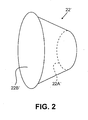
- FIG. 2 is a perspective view of an alternative embodiment of a susceptor suitable for use with the coating apparatus of FIG. 1 .
- the present invention provides an apparatus and method for coating work pieces while providing indirect thermal stabilization.
- One or more electron beams are directed at a susceptor that in turn radiates heat towards at least one work piece to help promote thermal stability during coating.
- the susceptor can be positioned downstream of the work piece, relative to a source of coating material, and can be shaped to include a central opening to allow excess coating material to pass through.
- the susceptor can be made from an oxide-ceramic material, or other suitable materials, and can have either a one-piece or multi-piece (e.g., segmented) construction.
- TBCs thermal barrier coatings
- FIG. 1 is a schematic illustration of one embodiment of a coating apparatus 10 that includes a process chamber 12, a plasma gun 14, a pumping assembly 16, a work piece support fixture 18, electron guns 20A and 20B, a susceptor 22 and a thermal hood 24.
- One or more work pieces 26 desired to be coated can be secured to the work piece support fixture 18.
- the work pieces 26 are turbine blades for a gas turbine engine, though it will be understood that the work pieces 26 can be nearly any type of component in further embodiments.
- the process chamber 12 provides a contained environment for application of the coating material to the work pieces 26.
- the process chamber 12 includes fluid-cooled walls, which can be cooled with water at approximately 15-20°C (60-70°F). Suitable passive thermal insulation (not shown) can be provided adjacent to the walls of the process chamber 12 in a known manner.
- the process chamber 12 defines an interior space that is held in a vacuum (i.e., a partial vacuum), with the vacuum in the range of approximately 66.66 Pa (0.5 Torr) to approximately 1.33 kPa (10 Torr).
- Aerodynamic windows 28 can be valve-like structures formed through the walls of the process chamber 12 that provide physical passageways through the walls of the process chamber 12 while still helping to maintain a desired pressure differential (e.g., maintaining the vacuum inside the process chamber 12).
- the plasma gun 14 is typically positioned within the process chamber 12.
- the plasma gun 14 can be of a known type that produces a plasma jet into which a coating material, such as a ceramic TBC powder, is introduced to produce a stream 30 that includes the coating material in a vapor phase.
- the stream 30 is directed toward the work pieces 26 and the work piece support fixture 18 to provide plasma-based physical vapor deposition (PVD) coating application.
- PVD physical vapor deposition
- the plasma gun 14 generates an immense amount of thermal energy within the process chamber 12, with temperatures typically ranging from approximately 871-1093°C (1600-2000°F) near the work pieces 26.
- temperatures typically ranging from approximately 871-1093°C (1600-2000°F) near the work pieces 26.
- the plasma gun 14 is the primary source of thermal energy used to heat the work pieces 26 to the desired temperature.
- the particular composition of the coating material can vary as desired for particular applications.
- the coating material can be nearly any type of TBC, bond coating, environmental coating, etc.
- Optimal coating process temperatures can vary for different coating materials.
- a different type of coating supply and delivery apparatus can be substituted for the plasma gun 14, as desired for particular applications.
- Excess coating material that is, coating material not deposited on the work pieces 26, can be cooled and collected by the pumping assembly 16.
- the pumping assembly is of a conventional configuration that allows for extraction and collection of excess coating material from the process chamber 12, as well as cooling of that excess coating material.
- the pumping assembly 16 is typically located at an end of the process chamber opposite the plasma gun 14. Because the pumping assembly 16 cools and removes the excess coating material, an end of the process chamber 12 where the pumping assembly 16 is located tends to exhibit cooler temperatures than in areas near the plasma gun 14.
- the work pieces 26 desired to be coated are secured to the work piece support fixture 18 in the path of the stream 30, downstream from the plasma gun 14.
- the work piece support fixture 18 can selectively index the work pieces 26 relative to the stream 30 and the plasma gun 14, in order to expose different portions of the work pieces 26 to the stream 30 in a uniform manner so that the coating material can cover all sides of the work pieces 26 substantially equally.
- the work piece support fixture 18 is configured to rotate the work pieces 26 in a planetary fashion, with all of the work pieces 26 commonly rotating about a central axis A and each of the work pieces 26 individually rotating about a dedicated axis A' or A".
- TBCs are sensitive to thermal conditions during the coating application process, and undesirable thermal conditions can cause detrimental microstructural properties of the TBCs formed on the work pieces 26.
- TBCs can develop striations and a cauliflower-like structure if temperature control at or near the work pieces 26 is poor.
- cyclic temperature variations common to prior art coating processes can cause separation between new, hot "layers" of the coating material from the stream 30 and cooler interfaces of previously-applied coating material already deposited on the work pieces 26, making resultant coatings undesirably friable and prone to separation.
- Temperature variations of 38°C (100°F) or more in process chambers are common with prior art plasma coating processes, and such large temperature variations tend to produce undesirable coating microstructures.
- the susceptor 22 and the thermal hood 24 can help reduce such temperature variations and help improve the resultant coating microstructure.
- the electron guns 20A and 20B can be positioned outside the process chamber 12, and can generate electron beams 32 directed into the process chamber 12 through the aerodynamic windows 28.
- the electron guns 20A and 20B can be differentially-pumped. Furthermore, locating the electron guns 20A and 20B outside of the process chamber 12 allows those guns 20A and 20B to be maintained at a different-and typically lower-operating pressure than the vacuum maintained inside the process chamber 12.
- Each of the electron guns 20A and 20B can have magnetic coils or other mechanisms used to control and direct the electron beams 32 in a desired manner, such as to allow scanning of the electron beams 32 in a rasterized fashion.
- two electron guns 20A and 20B are shown in the illustrated embodiment, any number of electron guns can be utilized in further embodiments, and only a single electron gun can be used in some embodiments.
- the susceptor 22 is positioned within the process chamber 12 generally adjacent to the work piece support fixture 18 at a location downstream from the work pieces 26.
- the work pieces 26 and the work piece support fixture 18 can be positioned in between the plasma gun 14 and the susceptor 22, with the susceptor 22 at an opposite side of the work pieces 26 from the plasma gun 14 (i.e., at a downstream side of the work pieces 26 that faces away from the oncoming stream 30) and with the susceptor 22 positioned in between the work pieces 26 and the pumping assembly 16.
- Any suitable means can be used to secure the susceptor 22 within the process chamber 12.
- the susceptor 22 defines a central opening 22A and an upstream face 22B.
- the susceptor 22 can have a one-piece (i.e., unitary) construction or can have a multi-piece configuration (e.g., as an assembly made up of a plurality of discrete segments). In the embodiment illustrated in FIG. 1 , the susceptor 22 has a substantially annular shape. In alternative embodiments the susceptor 22 can have other shapes.
- the susceptor 22 can be made of an oxide-based ceramic material.
- oxide-based ceramic susceptors are generally not degraded by deposition of ceramic coating material, thereby enhancing compatibility of the susceptor 22 with a ceramic deposition process such as with ceramic-based TBC deposition.
- Other materials, such as metallic materials, can also be used to make the susceptor 22 in further embodiments.
- the electron guns 20A and 20B direct the electron beams 32 at the upstream face 22B of the susceptor 22.
- the electron guns 20A and 20B can scan the electron beams 32 across at least portions of the upstream face 22B of the susceptor 22, thereby allowing the electron beams 32 to remain relatively focused while still directing energy to a relatively large area of the upstream face 22B.
- the electron beams 32 cause the susceptor 22 to radiate heat, designated by an arrow H in FIG. 1 .
- the susceptor 22 can be positioned such that the heat H radiating is directed toward the work piece support fixture 18 to heat the work pieces 26.
- the susceptor 22 can be positioned such that the heat H is radiated in a generally axial direction relative to the stream 30 to heat portions of the work pieces 26 facing away from the plasma gun 14 and the oncoming stream 30 (i.e., downstream portions of the work pieces 26).
- the additional heat generated by the susceptor 22 helps to thermally stabilize the work pieces 26, and reduce cyclical heat and cooling effects caused by rotation of the work pieces 26 relative to the plasma gun 14 and the stream 30.
- the heat H that is radiated from the susceptor 22 helps reduce or prevent temperature loss as the work pieces 26 rotate and face an aft, downstream portion of the process chamber 12 where the pumping assembly 16 is located.
- the electron guns 20A and 20B can be positioned such that the electron beams 32 can reach the susceptor 22 without crossing the stream 30, including related plumes of the coating material present inside the process chamber 12.
- the coating material in the stream 30 would tend to obstruct the electron beams 32 and thereby decrease the amount of energy delivered to the susceptor 22.
- viewing angles of the electron guns 20A and 20B relative to the susceptor 22 can be provided so that the electron beams 32 need not cross or otherwise intersect or partially pass through the stream 30.
- the thermal hood 24 is positioned inside the process chamber 12 to partially surround the work piece support fixture 18 and the work pieces 26 to provide thermal shielding to help maintain thermal stabilization of the work pieces 26.
- the thermal hood 24 is configured to provide reflective infrared shielding.
- the thermal hood 24 includes upstream and downstream openings for accepting the stream 30 from the plasma gun 14, and also allowing excess coating material to pass through toward the pumping assembly 16.
- the thermal hood 24 can be moveable (using any suitable actuation mechanism) to further help regulate thermal conditions in the process chamber 12.
- the thermal hood 24 can be omitted.
- FIG. 2 is a perspective view of an alternative embodiment of a susceptor 22' that is suitable for use with the coating apparatus 10.
- the susceptor 22' includes a central opening 22A' and an upstream face 22B'. Operation and construction of the susceptor 22' is generally similar to that of the susceptor 22 described above. However, in the embodiment shown in FIG. 2 , the susceptor 22' has a substantially frusto-conical shape. It is generally beneficial to maintain a perpendicular orientation between the susceptor 22' and each of the work pieces 26, regardless of the particular orientation of the work pieces 26 over time as they are rotated. The frusto-conical shape of the susceptor 22' helps maintain such a perpendicular orientation relative to the work pieces 26, such that the radiated heat from the susceptor 22' is distributed relatively evenly to the work pieces 26.
- heat provided by a susceptor according to the present invention helps reduce or prevent microstructure degradation caused by cyclic cooling and heating of an applied coating as the coating is deposited on a work piece. More specifically, an approximately 38°C (100°F) or greater surface temperature variation on work pieces can be reduced to approximately 12°C (10°F) or less.
- the present invention helps to maintain work pieces at a desired and relatively uniform temperature to help ensure that the deposited coating (e.g., TBC) is of dependably aircraft quality and suitable for flight service.
- the present invention can help provide desirable columnar TBC microstructures on work pieces.
Landscapes
- Chemical & Material Sciences (AREA)
- Engineering & Computer Science (AREA)
- Chemical Kinetics & Catalysis (AREA)
- Materials Engineering (AREA)
- Mechanical Engineering (AREA)
- Metallurgy (AREA)
- Organic Chemistry (AREA)
- Physics & Mathematics (AREA)
- Plasma & Fusion (AREA)
- Coating By Spraying Or Casting (AREA)
- Physical Vapour Deposition (AREA)
Abstract
Description
- The present invention relates to coating apparatuses and methods of applying coatings.
- Coatings are utilized in a variety of settings to provide a variety of benefits. For example, modem gas turbine engines can include thermal barrier coatings (TBCs), environmental coatings, etc. to help promote efficient and reliable operation. Application of coatings can involve a variety of different application methods, such as plasma-based physical vapor deposition (PVD). When TBCs are applied to gas turbine engine components, such as blades and vanes, using plasma-based-PVD, the components being coated are rotated within a process chamber while a plasma stream directs the coating material at the components. Examples of such known coating processes are disclosed in
U.S. Pat. No. 7,482,035 and inU.S. Pat. App. Pub. Nos. 2007/0259173A1 and2008/0226837A1 . - A significant problem with known plasma-based PVD processes is the loss of work-piece temperature to down-stream portions of the plasma-based PVD equipment. A plasma gun generating the plasma stream is the only source of heat in the system. The walls of the process chamber are typically cooled to approximately 15-20°C, and thereby remove heat from the process chamber, and a downstream end of the process chamber includes equipment to collect and cool excess coating material, thereby also removing thermal energy from the process chamber. Components being coated tend to be cyclically heated and cooled as they rotate because portions of the components that face downstream and away from the plasma stream cool to lower temperatures. TBCs are sensitive to thermal conditions during the coating application process, and undesirable thermal conditions can cause detrimental changes to the microstructure of the TBC. In particular, the TBC develops striations and a cauliflower-like structure due to poor temperature control. While in a typical application it is desired to maintain the components being coated at a temperature of approximately 1038°C (1900°F), temperatures can range from approximately 871-1093°C (1600-2000°F). Moreover, as portions of the components being coated are rotated back to face the plasma stream, separation between new, hot layers of the coating and the cooler interface of previously-applied coating material can make the resultant coating undesirably friable and prone to separation between layers of the coating. These microstructural characteristics are known to cause a debit in service life for the turbine engine component.
- One approach known in the art for providing temperature control involves passive thermal shielding. However, passive thermal shielding mitigates only off-axis heat loss to a relatively cold process chamber. The core reason for this effect is the flow-through nature of the coating vapor stream created via the plasma stream. Laterally-oriented passive spray shielding is incapable of ensuring heat-loss from down-stream areas of the process chamber where the plasma plume and waste ceramic vapor are cooled and collected for extraction from the process chamber.
- Thus, it is desired to provide a coating apparatus and method with improved thermal stabilization.
- An apparatus according to the present invention includes a work piece support for holding and selectively rotating a work piece, a coating delivery apparatus configured to apply a coating material to the work piece, a susceptor positioned adjacent to the work piece support, and a first electron gun configured to direct a first electron beam at the susceptor such that the susceptor radiates heat toward the work piece.
-
FIG. 1 is a schematic illustration of a coating apparatus according to the present invention. -
FIG. 2 is a perspective view of an alternative embodiment of a susceptor suitable for use with the coating apparatus ofFIG. 1 . - In general, the present invention provides an apparatus and method for coating work pieces while providing indirect thermal stabilization. One or more electron beams are directed at a susceptor that in turn radiates heat towards at least one work piece to help promote thermal stability during coating. The susceptor can be positioned downstream of the work piece, relative to a source of coating material, and can be shaped to include a central opening to allow excess coating material to pass through. The susceptor can be made from an oxide-ceramic material, or other suitable materials, and can have either a one-piece or multi-piece (e.g., segmented) construction. The present invention is suitable for applying thermal barrier coatings (TBCs) to gas turbine engine components, in addition to other uses.
-
FIG. 1 is a schematic illustration of one embodiment of acoating apparatus 10 that includes aprocess chamber 12, aplasma gun 14, apumping assembly 16, a workpiece support fixture 18,electron guns susceptor 22 and athermal hood 24. One ormore work pieces 26 desired to be coated can be secured to the workpiece support fixture 18. In the illustrated embodiment, thework pieces 26 are turbine blades for a gas turbine engine, though it will be understood that thework pieces 26 can be nearly any type of component in further embodiments. - The
process chamber 12 provides a contained environment for application of the coating material to thework pieces 26. In the illustrated embodiment, theprocess chamber 12 includes fluid-cooled walls, which can be cooled with water at approximately 15-20°C (60-70°F). Suitable passive thermal insulation (not shown) can be provided adjacent to the walls of theprocess chamber 12 in a known manner. Theprocess chamber 12 defines an interior space that is held in a vacuum (i.e., a partial vacuum), with the vacuum in the range of approximately 66.66 Pa (0.5 Torr) to approximately 1.33 kPa (10 Torr).Aerodynamic windows 28 can be valve-like structures formed through the walls of theprocess chamber 12 that provide physical passageways through the walls of theprocess chamber 12 while still helping to maintain a desired pressure differential (e.g., maintaining the vacuum inside the process chamber 12). - The
plasma gun 14 is typically positioned within theprocess chamber 12. Theplasma gun 14 can be of a known type that produces a plasma jet into which a coating material, such as a ceramic TBC powder, is introduced to produce astream 30 that includes the coating material in a vapor phase. Thestream 30 is directed toward thework pieces 26 and the work piece supportfixture 18 to provide plasma-based physical vapor deposition (PVD) coating application. During operation, theplasma gun 14 generates an immense amount of thermal energy within theprocess chamber 12, with temperatures typically ranging from approximately 871-1093°C (1600-2000°F) near thework pieces 26. For a typical ceramic TBC, it is desirable to coat thework pieces 26 at a temperature of approximately 1038°C (1900°F). Theplasma gun 14 is the primary source of thermal energy used to heat thework pieces 26 to the desired temperature. It will be appreciated by those of ordinary skill in the art that the particular composition of the coating material can vary as desired for particular applications. For instance, the coating material can be nearly any type of TBC, bond coating, environmental coating, etc. Optimal coating process temperatures can vary for different coating materials. Moreover, in alternative embodiments a different type of coating supply and delivery apparatus can be substituted for theplasma gun 14, as desired for particular applications. - Excess coating material, that is, coating material not deposited on the
work pieces 26, can be cooled and collected by thepumping assembly 16. In the illustrated embodiment, the pumping assembly is of a conventional configuration that allows for extraction and collection of excess coating material from theprocess chamber 12, as well as cooling of that excess coating material. Thepumping assembly 16 is typically located at an end of the process chamber opposite theplasma gun 14. Because thepumping assembly 16 cools and removes the excess coating material, an end of theprocess chamber 12 where thepumping assembly 16 is located tends to exhibit cooler temperatures than in areas near theplasma gun 14. - In the illustrated embodiment, the
work pieces 26 desired to be coated are secured to the workpiece support fixture 18 in the path of thestream 30, downstream from theplasma gun 14. The work piece supportfixture 18 can selectively index thework pieces 26 relative to thestream 30 and theplasma gun 14, in order to expose different portions of thework pieces 26 to thestream 30 in a uniform manner so that the coating material can cover all sides of thework pieces 26 substantially equally. In one embodiment, the workpiece support fixture 18 is configured to rotate thework pieces 26 in a planetary fashion, with all of thework pieces 26 commonly rotating about a central axis A and each of thework pieces 26 individually rotating about a dedicated axis A' or A". - Because portions of the
work pieces 26 are rotated away from theplasma gun 14 and thestream 30 at times, those portions are generally not heated by theplasma gun 14 and thestream 30 as much as those portions facing theplasma gun 14 and thestream 30. Coatings like TBCs are sensitive to thermal conditions during the coating application process, and undesirable thermal conditions can cause detrimental microstructural properties of the TBCs formed on thework pieces 26. In particular, TBCs can develop striations and a cauliflower-like structure if temperature control at or near thework pieces 26 is poor. Moreover, cyclic temperature variations common to prior art coating processes can cause separation between new, hot "layers" of the coating material from thestream 30 and cooler interfaces of previously-applied coating material already deposited on thework pieces 26, making resultant coatings undesirably friable and prone to separation. Temperature variations of 38°C (100°F) or more in process chambers are common with prior art plasma coating processes, and such large temperature variations tend to produce undesirable coating microstructures. As explained further below, thesusceptor 22 and thethermal hood 24 can help reduce such temperature variations and help improve the resultant coating microstructure. - The
electron guns process chamber 12, and can generateelectron beams 32 directed into theprocess chamber 12 through theaerodynamic windows 28. Theelectron guns electron guns process chamber 12 allows thoseguns process chamber 12. Each of theelectron guns electron beams 32 in a desired manner, such as to allow scanning of theelectron beams 32 in a rasterized fashion. Although twoelectron guns - The
susceptor 22 is positioned within theprocess chamber 12 generally adjacent to the workpiece support fixture 18 at a location downstream from thework pieces 26. In other words, thework pieces 26 and the workpiece support fixture 18 can be positioned in between theplasma gun 14 and thesusceptor 22, with thesusceptor 22 at an opposite side of thework pieces 26 from the plasma gun 14 (i.e., at a downstream side of thework pieces 26 that faces away from the oncoming stream 30) and with thesusceptor 22 positioned in between thework pieces 26 and the pumpingassembly 16. Any suitable means can be used to secure thesusceptor 22 within theprocess chamber 12. Thesusceptor 22 defines acentral opening 22A and anupstream face 22B. Excess coating material from thestream 30 can pass through theopening 22A, thereby allowing that excess coating material to be collected downstream by the pumpingassembly 16. Thesusceptor 22 can have a one-piece (i.e., unitary) construction or can have a multi-piece configuration (e.g., as an assembly made up of a plurality of discrete segments). In the embodiment illustrated inFIG. 1 , thesusceptor 22 has a substantially annular shape. In alternative embodiments thesusceptor 22 can have other shapes. Thesusceptor 22 can be made of an oxide-based ceramic material. The effectiveness of oxide-based ceramic susceptors is generally not degraded by deposition of ceramic coating material, thereby enhancing compatibility of thesusceptor 22 with a ceramic deposition process such as with ceramic-based TBC deposition. Other materials, such as metallic materials, can also be used to make thesusceptor 22 in further embodiments. - During operation, the
electron guns electron beams 32 at theupstream face 22B of thesusceptor 22. Theelectron guns electron beams 32 across at least portions of theupstream face 22B of thesusceptor 22, thereby allowing theelectron beams 32 to remain relatively focused while still directing energy to a relatively large area of theupstream face 22B. The electron beams 32 cause thesusceptor 22 to radiate heat, designated by an arrow H inFIG. 1 . Thesusceptor 22 can be positioned such that the heat H radiating is directed toward the workpiece support fixture 18 to heat thework pieces 26. Furthermore, thesusceptor 22 can be positioned such that the heat H is radiated in a generally axial direction relative to thestream 30 to heat portions of thework pieces 26 facing away from theplasma gun 14 and the oncoming stream 30 (i.e., downstream portions of the work pieces 26). The additional heat generated by thesusceptor 22 helps to thermally stabilize thework pieces 26, and reduce cyclical heat and cooling effects caused by rotation of thework pieces 26 relative to theplasma gun 14 and thestream 30. In other words, the heat H that is radiated from thesusceptor 22 helps reduce or prevent temperature loss as thework pieces 26 rotate and face an aft, downstream portion of theprocess chamber 12 where the pumpingassembly 16 is located. - The
electron guns electron beams 32 can reach thesusceptor 22 without crossing thestream 30, including related plumes of the coating material present inside theprocess chamber 12. The coating material in thestream 30 would tend to obstruct theelectron beams 32 and thereby decrease the amount of energy delivered to thesusceptor 22. By positioning theelectron guns process chamber 12, viewing angles of theelectron guns susceptor 22 can be provided so that theelectron beams 32 need not cross or otherwise intersect or partially pass through thestream 30. - The
thermal hood 24 is positioned inside theprocess chamber 12 to partially surround the workpiece support fixture 18 and thework pieces 26 to provide thermal shielding to help maintain thermal stabilization of thework pieces 26. In one embodiment, thethermal hood 24 is configured to provide reflective infrared shielding. Thethermal hood 24 includes upstream and downstream openings for accepting thestream 30 from theplasma gun 14, and also allowing excess coating material to pass through toward the pumpingassembly 16. In some embodiments, thethermal hood 24 can be moveable (using any suitable actuation mechanism) to further help regulate thermal conditions in theprocess chamber 12. In further embodiments, thethermal hood 24 can be omitted. -
FIG. 2 is a perspective view of an alternative embodiment of a susceptor 22' that is suitable for use with thecoating apparatus 10. The susceptor 22' includes acentral opening 22A' and anupstream face 22B'. Operation and construction of the susceptor 22' is generally similar to that of thesusceptor 22 described above. However, in the embodiment shown inFIG. 2 , the susceptor 22' has a substantially frusto-conical shape. It is generally beneficial to maintain a perpendicular orientation between the susceptor 22' and each of thework pieces 26, regardless of the particular orientation of thework pieces 26 over time as they are rotated. The frusto-conical shape of the susceptor 22' helps maintain such a perpendicular orientation relative to thework pieces 26, such that the radiated heat from the susceptor 22' is distributed relatively evenly to thework pieces 26. - It will be recognized that the present invention provides numerous advantages and benefits. For example, heat provided by a susceptor according to the present invention helps reduce or prevent microstructure degradation caused by cyclic cooling and heating of an applied coating as the coating is deposited on a work piece. More specifically, an approximately 38°C (100°F) or greater surface temperature variation on work pieces can be reduced to approximately 12°C (10°F) or less. Thus, the present invention helps to maintain work pieces at a desired and relatively uniform temperature to help ensure that the deposited coating (e.g., TBC) is of dependably aircraft quality and suitable for flight service. For instance, the present invention can help provide desirable columnar TBC microstructures on work pieces.
- While the invention has been described with reference to an exemplary embodiment(s), it will be understood by those skilled in the art that various changes may be made and equivalents may be substituted for elements thereof without departing from the scope of the invention, which is defined by the claims. In addition, many modifications may be made to adapt a particular situation or material to the teachings of the invention without departing from the essential scope thereof. Therefore, it is intended that the invention not be limited to the particular embodiment(s) disclosed, but that the invention will include all embodiments falling within the scope of the appended claims. For example, components of the coating apparatus described above can be positioned only partially within the process chamber. Moreover, the particular configuration and arrangement of components of the coating apparatus can vary as desired for particular applications.
Claims (15)
- An apparatus (10) comprising:a work piece support (18) for holding and rotating a work piece (26);a coating delivery apparatus (14) configured to apply a coating material to the work piece;a susceptor (22,22') positioned adjacent to the work piece support; anda first electron gun (20A) configured to direct a first electron beam at the susceptor such that the susceptor radiates heat toward the work piece.
- The apparatus of claim 1, wherein the coating delivery apparatus comprises a plasma gun (14) for plasma-based spray deposition of the coating material on the work piece; and/or wherein the work piece support (18) is positioned between the coating delivery apparatus (14) and the susceptor (22,22').
- The apparatus of claim 1 or 2, wherein the susceptor (22) has an annular shape; wherein the susceptor (22') has a frusto-conical shape.
- The apparatus of claim 1, 2 or 3, wherein the susceptor (22,22') is formed as a single piece; or wherein the susceptor (22,22') has a segmented configuration.
- The apparatus of claim 1, 2, 3, or 4, wherein the susceptor has a central opening (22A,22A') configured to allow excess coating material to pass through the susceptor; and or wherein the susceptor (22,22') comprises an oxide-based ceramic material.
- The apparatus of any preceding claim and further comprising:a process chamber (12), wherein the coating delivery apparatus, the work piece support and the susceptor are each positioned at least partially within the process chamber; and preferably further comprising:a pumping assembly for maintaining an interior of the process chamber in a vacuum during applying of the coating material, preferably in a range from approximately 66.66 Pa (0.5 Torr) to approximately 1.33 kPa (10 Torr).
- The apparatus of claim 6 and further comprising:an aerodynamic window (28) defined through a wall of the process chamber, wherein the first electron gun is located outside the process chamber and positioned to direct the first electron beam through the aerodynamic window to the susceptor.
- The apparatus of claim 6 or 7 and further comprising:a thermal hood (24) located at least partially inside the process chamber, wherein the thermal hood partially surrounds the work piece support to provide thermal shielding, and wherein the thermal hood includes an opening for accepting a stream of the coating material from the coating apparatus; preferably wherein the thermal hood provides reflective infrared shielding.
- The apparatus of any preceding claim and further comprising:a second electron gun (20B) configured to direct a second electron beam at the susceptor, wherein the second electron gun is arranged at an opposite side of the work piece support from the first electron gun.
- The apparatus of any preceding claim, wherein the or each electron gun is positioned such that its electron beam can reach the susceptor without crossing a stream of the coating material from the coating delivery apparatus.
- A method of coating a workpiece comprising:positioning a work piece in between a coating supply location and a susceptor;rotating the work piece;depositing a coating from the coating supply location onto the rotating work piece;heating the work piece with thermal energy emanating from the coating supply location; anddirecting a first electron beam at the susceptor to cause heat to be radiated from the susceptor to the work piece.
- The method of claim 11, wherein the step of depositing a coating onto the rotating work piece is performed using a plasma gun to spray the coating onto the work piece in a plasma-based jet; and or wherein the work piece is rotated more than 360° such that the coating is deposited over previously-deposited material of the coating.
- The method of claim 11 or 12, wherein the heat radiated from the susceptor to the work piece thermally stabilizes previously-deposited material of the coating rotated away from the coating supply location emanating thermal energy.
- The method of claim 11, 12 or 13 and further comprising:directing a second electron beam at the susceptor, wherein neither the first electron beam nor the second electron beam crosses a stream of the coating emanating from the coating supply location.
- The method of claim 11, 12, 13 or 14 and further comprising:scanning the or each electron beam across a surface of the susceptor.
Applications Claiming Priority (1)
| Application Number | Priority Date | Filing Date | Title |
|---|---|---|---|
| US12/723,436 US8328945B2 (en) | 2010-03-12 | 2010-03-12 | Coating apparatus and method with indirect thermal stabilization |
Publications (1)
| Publication Number | Publication Date |
|---|---|
| EP2369036A1 true EP2369036A1 (en) | 2011-09-28 |
Family
ID=43855997
Family Applications (1)
| Application Number | Title | Priority Date | Filing Date |
|---|---|---|---|
| EP11250293A Withdrawn EP2369036A1 (en) | 2010-03-12 | 2011-03-11 | Coating apparatus and method |
Country Status (2)
| Country | Link |
|---|---|
| US (1) | US8328945B2 (en) |
| EP (1) | EP2369036A1 (en) |
Families Citing this family (3)
| Publication number | Priority date | Publication date | Assignee | Title |
|---|---|---|---|---|
| US9109289B2 (en) | 2011-06-27 | 2015-08-18 | United Technologies Corporation | Manipulator for coating application |
| US20170218505A1 (en) | 2016-02-03 | 2017-08-03 | United Technologies Corporation | System and Method for Low Thermal Shock-Fast Cooling of Thermal Barrier Coating |
| CN106399903A (en) * | 2016-06-22 | 2017-02-15 | 南通东方科技有限公司 | Rotating system for plasma cladding of substrate |
Citations (9)
| Publication number | Priority date | Publication date | Assignee | Title |
|---|---|---|---|---|
| US3560252A (en) * | 1968-08-13 | 1971-02-02 | Air Reduction | Vapor deposition method including specified solid angle of radiant heater |
| DE4135326C1 (en) * | 1991-10-25 | 1993-06-09 | Siemens Ag, 8000 Muenchen, De | Coating components by thermal spraying - using preheating kiln to heat workpiece before plasma spraying in vacuum chamber |
| GB2323855A (en) * | 1997-04-01 | 1998-10-07 | Ion Coat Ltd | Depositing a coating on a conductive substrate using positive bias and electron bombardment |
| US20030203127A1 (en) * | 2002-04-30 | 2003-10-30 | General Electric Company | Method of controlling temperature during coating deposition by EBPVD |
| US6946034B1 (en) * | 1999-08-04 | 2005-09-20 | General Electric Company | Electron beam physical vapor deposition apparatus |
| US20070259173A1 (en) | 2006-05-05 | 2007-11-08 | Sulzer Metco Ag | Method for the manufacture of a coating |
| US20080226837A1 (en) | 2006-10-02 | 2008-09-18 | Sulzer Metco Ag | Method for the manufacture of a coating having a columnar structure |
| US7482035B2 (en) | 2003-05-23 | 2009-01-27 | Sulzer Metco Ag | Method of coating a substrate by a thermal application of the coating material |
| EP2157204A1 (en) * | 2008-08-22 | 2010-02-24 | United Technologies Corporation | Deposition apparatus having thermal hood |
Family Cites Families (28)
| Publication number | Priority date | Publication date | Assignee | Title |
|---|---|---|---|---|
| GB1500701A (en) * | 1974-01-24 | 1978-02-08 | Atomic Energy Authority Uk | Vapour deposition apparatus |
| US4481237A (en) | 1981-12-14 | 1984-11-06 | United Technologies Corporation | Method of applying ceramic coatings on a metallic substrate |
| US4795656A (en) * | 1986-08-26 | 1989-01-03 | Kozo Iizuka, Director-General, Agency Of Industrial Science And Technology | Cluster ion plating method for producing electrically conductive carbon film |
| US4876114A (en) * | 1987-09-23 | 1989-10-24 | International Business Machines Corporation | Process for the self fractionation deposition of a metallic layer on a workpiece |
| US5047612A (en) * | 1990-02-05 | 1991-09-10 | General Electric Company | Apparatus and method for controlling powder deposition in a plasma spray process |
| JP3255469B2 (en) * | 1992-11-30 | 2002-02-12 | 三菱電機株式会社 | Laser thin film forming equipment |
| US5792521A (en) | 1996-04-18 | 1998-08-11 | General Electric Company | Method for forming a multilayer thermal barrier coating |
| DE59702062D1 (en) | 1996-05-30 | 2000-08-24 | Siemens Ag | COATING DEVICE AND METHOD FOR COATING A COMPONENT WITH A THERMAL INSULATION LAYER |
| US6054184A (en) | 1996-06-04 | 2000-04-25 | General Electric Company | Method for forming a multilayer thermal barrier coating |
| US6245152B1 (en) * | 1996-07-05 | 2001-06-12 | Super Silicon Crystal Research Institute Corp. | Method and apparatus for producing epitaxial wafer |
| US6083322A (en) | 1997-03-06 | 2000-07-04 | United Technologies Corporation | Modular coating fixture |
| US6217662B1 (en) | 1997-03-24 | 2001-04-17 | Cree, Inc. | Susceptor designs for silicon carbide thin films |
| EP1029103B1 (en) | 1997-11-03 | 2001-09-19 | Siemens Aktiengesellschaft | Coating method and device |
| JP3796030B2 (en) * | 1997-11-16 | 2006-07-12 | キヤノンアネルバ株式会社 | Thin film production equipment |
| US5998003A (en) | 1998-09-10 | 1999-12-07 | Electric Power Research Institute, Inc. | Multilayer nanostructured ceramic thermal barrier coatings |
| US5986233A (en) * | 1998-12-30 | 1999-11-16 | The United States Of America As Represented By The United States Department Of Energy | Susceptor heating device for electron beam brazing |
| US6983718B1 (en) | 1999-08-04 | 2006-01-10 | General Electric Company | Electron beam physical vapor deposition apparatus |
| US6365236B1 (en) | 1999-12-20 | 2002-04-02 | United Technologies Corporation | Method for producing ceramic coatings containing layered porosity |
| US6605352B1 (en) | 2000-01-06 | 2003-08-12 | Saint-Gobain Ceramics & Plastics, Inc. | Corrosion and erosion resistant thin film diamond coating and applications therefor |
| DE10102991C2 (en) | 2000-02-19 | 2003-11-20 | Ald Vacuum Techn Ag | Device for heating a metal workpiece |
| SG106639A1 (en) * | 2000-10-10 | 2004-10-29 | Gen Electric | Apparatus and method for introducing small amounts of refractory elements into a vapor deposition coating |
| EP1293587A1 (en) * | 2001-09-14 | 2003-03-19 | Kabushiki Kaisha Kobe Seiko Sho | Vacuum coating apparatus with central heater |
| JP2004055401A (en) * | 2002-07-22 | 2004-02-19 | Sony Corp | Organic film forming equipment |
| US6635124B1 (en) | 2002-08-29 | 2003-10-21 | General Electric Company | Method of depositing a thermal barrier coating |
| JP4361747B2 (en) * | 2003-03-04 | 2009-11-11 | 東京エレクトロン株式会社 | Thin film formation method |
| JP2005183834A (en) * | 2003-12-22 | 2005-07-07 | Toshiba Ceramics Co Ltd | Barrel type susceptor |
| US7732739B2 (en) * | 2004-10-19 | 2010-06-08 | Canon Anelva Corporation | Substrate heat treatment apparatus and substrate transfer tray used in substrate heat treatment |
| US20080166489A1 (en) | 2005-08-04 | 2008-07-10 | United Technologies Corporation | Method for microstructure control of ceramic thermal spray coating |
-
2010
- 2010-03-12 US US12/723,436 patent/US8328945B2/en not_active Expired - Fee Related
-
2011
- 2011-03-11 EP EP11250293A patent/EP2369036A1/en not_active Withdrawn
Patent Citations (9)
| Publication number | Priority date | Publication date | Assignee | Title |
|---|---|---|---|---|
| US3560252A (en) * | 1968-08-13 | 1971-02-02 | Air Reduction | Vapor deposition method including specified solid angle of radiant heater |
| DE4135326C1 (en) * | 1991-10-25 | 1993-06-09 | Siemens Ag, 8000 Muenchen, De | Coating components by thermal spraying - using preheating kiln to heat workpiece before plasma spraying in vacuum chamber |
| GB2323855A (en) * | 1997-04-01 | 1998-10-07 | Ion Coat Ltd | Depositing a coating on a conductive substrate using positive bias and electron bombardment |
| US6946034B1 (en) * | 1999-08-04 | 2005-09-20 | General Electric Company | Electron beam physical vapor deposition apparatus |
| US20030203127A1 (en) * | 2002-04-30 | 2003-10-30 | General Electric Company | Method of controlling temperature during coating deposition by EBPVD |
| US7482035B2 (en) | 2003-05-23 | 2009-01-27 | Sulzer Metco Ag | Method of coating a substrate by a thermal application of the coating material |
| US20070259173A1 (en) | 2006-05-05 | 2007-11-08 | Sulzer Metco Ag | Method for the manufacture of a coating |
| US20080226837A1 (en) | 2006-10-02 | 2008-09-18 | Sulzer Metco Ag | Method for the manufacture of a coating having a columnar structure |
| EP2157204A1 (en) * | 2008-08-22 | 2010-02-24 | United Technologies Corporation | Deposition apparatus having thermal hood |
Also Published As
| Publication number | Publication date |
|---|---|
| US8328945B2 (en) | 2012-12-11 |
| US20110223356A1 (en) | 2011-09-15 |
Similar Documents
| Publication | Publication Date | Title |
|---|---|---|
| EP3483394B1 (en) | Spray nozzle device for delivering a restorative coating through a hole in a case of a turbine engine | |
| EP2157204B1 (en) | Deposition apparatus having thermal hood | |
| EP2233599B1 (en) | Method for microstructure control of ceramic thermally sprayed coatings | |
| JP6203475B2 (en) | Component manipulator, coating method, and use of component manipulator for dynamically positioning a substrate | |
| US20210323008A1 (en) | Spray nozzle device for delivering a restorative coating through a hole in a case of a turbine engine | |
| US20200095666A1 (en) | Abradable coating | |
| JP2012082519A (en) | Method of manufacturing thermal barrier coating structure | |
| CN112063962B (en) | Method for preparing uniform coating on complex profile surface by PS-PVD | |
| CN102443752A (en) | Thermal spraying process for keeping cooling air hole smooth | |
| SG182119A1 (en) | Coating deposition apparatus and method therefor | |
| US8328945B2 (en) | Coating apparatus and method with indirect thermal stabilization | |
| US10151245B2 (en) | Fixturing for thermal spray coating of gas turbine components | |
| US8350180B2 (en) | High pressure pre-oxidation for deposition of thermal barrier coating with hood | |
| EP1008669A1 (en) | Apparatus for electron beam physical vapor deposition | |
| EP2369027B1 (en) | Thermal stabilization of coating material vapor stream | |
| EP2369037A1 (en) | Coating method and apparatus | |
| CN114059020A (en) | A device and method for improving gas phase ratio in PS-PVD deposition process | |
| EP3719168B1 (en) | Electron beam vapor deposition process | |
| KR20220011696A (en) | Methods for producing dense improved coatings of increased crystalline | |
| EP3061844B1 (en) | Methods for optimal source material deposition along hole edges | |
| KR20070016943A (en) | Microstructure Control Method of Ceramic Thermal Spray Coating |
Legal Events
| Date | Code | Title | Description |
|---|---|---|---|
| PUAI | Public reference made under article 153(3) epc to a published international application that has entered the european phase |
Free format text: ORIGINAL CODE: 0009012 |
|
| AK | Designated contracting states |
Kind code of ref document: A1 Designated state(s): AL AT BE BG CH CY CZ DE DK EE ES FI FR GB GR HR HU IE IS IT LI LT LU LV MC MK MT NL NO PL PT RO RS SE SI SK SM TR |
|
| AX | Request for extension of the european patent |
Extension state: BA ME |
|
| 17P | Request for examination filed |
Effective date: 20111219 |
|
| 17Q | First examination report despatched |
Effective date: 20130830 |
|
| GRAP | Despatch of communication of intention to grant a patent |
Free format text: ORIGINAL CODE: EPIDOSNIGR1 |
|
| INTG | Intention to grant announced |
Effective date: 20150122 |
|
| STAA | Information on the status of an ep patent application or granted ep patent |
Free format text: STATUS: THE APPLICATION IS DEEMED TO BE WITHDRAWN |
|
| 18D | Application deemed to be withdrawn |
Effective date: 20150602 |