EP2368855A2 - Apparatus for heating glass sheets for tempering - Google Patents
Apparatus for heating glass sheets for tempering Download PDFInfo
- Publication number
- EP2368855A2 EP2368855A2 EP11153994A EP11153994A EP2368855A2 EP 2368855 A2 EP2368855 A2 EP 2368855A2 EP 11153994 A EP11153994 A EP 11153994A EP 11153994 A EP11153994 A EP 11153994A EP 2368855 A2 EP2368855 A2 EP 2368855A2
- Authority
- EP
- European Patent Office
- Prior art keywords
- furnace
- nozzle
- heating
- degrees
- enclosures
- Prior art date
- Legal status (The legal status is an assumption and is not a legal conclusion. Google has not performed a legal analysis and makes no representation as to the accuracy of the status listed.)
- Withdrawn
Links
- 239000011521 glass Substances 0.000 title claims abstract description 33
- 238000010438 heat treatment Methods 0.000 title claims abstract description 18
- 238000005496 tempering Methods 0.000 title claims abstract description 9
- 230000001154 acute effect Effects 0.000 claims abstract description 4
- 238000005422 blasting Methods 0.000 claims abstract description 4
- 238000004891 communication Methods 0.000 claims description 2
- 238000009826 distribution Methods 0.000 claims description 2
- 238000010791 quenching Methods 0.000 description 5
- 230000000171 quenching effect Effects 0.000 description 5
- 238000007664 blowing Methods 0.000 description 2
- 238000002360 preparation method Methods 0.000 description 2
- 239000005341 toughened glass Substances 0.000 description 2
- 230000001419 dependent effect Effects 0.000 description 1
- 230000018109 developmental process Effects 0.000 description 1
- 238000000034 method Methods 0.000 description 1
- 230000011218 segmentation Effects 0.000 description 1
- 238000004904 shortening Methods 0.000 description 1
Images
Classifications
-
- C—CHEMISTRY; METALLURGY
- C03—GLASS; MINERAL OR SLAG WOOL
- C03B—MANUFACTURE, SHAPING, OR SUPPLEMENTARY PROCESSES
- C03B25/00—Annealing glass products
- C03B25/04—Annealing glass products in a continuous way
- C03B25/10—Annealing glass products in a continuous way with vertical displacement of the glass products
- C03B25/12—Annealing glass products in a continuous way with vertical displacement of the glass products of glass sheets
-
- C—CHEMISTRY; METALLURGY
- C03—GLASS; MINERAL OR SLAG WOOL
- C03B—MANUFACTURE, SHAPING, OR SUPPLEMENTARY PROCESSES
- C03B29/00—Reheating glass products for softening or fusing their surfaces; Fire-polishing; Fusing of margins
- C03B29/04—Reheating glass products for softening or fusing their surfaces; Fire-polishing; Fusing of margins in a continuous way
- C03B29/06—Reheating glass products for softening or fusing their surfaces; Fire-polishing; Fusing of margins in a continuous way with horizontal displacement of the products
- C03B29/08—Glass sheets
-
- C—CHEMISTRY; METALLURGY
- C03—GLASS; MINERAL OR SLAG WOOL
- C03B—MANUFACTURE, SHAPING, OR SUPPLEMENTARY PROCESSES
- C03B27/00—Tempering or quenching glass products
- C03B27/04—Tempering or quenching glass products using gas
- C03B27/044—Tempering or quenching glass products using gas for flat or bent glass sheets being in a horizontal position
Definitions
- the present invention relates to an apparatus for heating glass sheets for tempering, said apparatus comprising:
- the nozzle enclosures are positioned in an almost longitudinal direction relative to the glass direction and at a distance of about 120 mm from each other.
- the jet orifices present in the nozzle deck are about 10 mm in diameter.
- the orifices are typically arranged in three rows. Each row of orifices is spaced from the next one.
- the nozzle enclosure, including its open resistor, is about 2 meters in length.
- an object of the present invention is to reduce substantially or at least to minimize the foregoing problem with tempering furnaces.
- an object of the invention is to reduce in tempered glass the occurrence of anisotropy taking place during the course of tempering.
- the above-mentioned object of the invention is attained according to the present invention in such a way that the nozzle enclosures lengthwise of the furnace are disposed at an acute angle relative to the glass traveling direction, said angle being at least 2 degrees, preferably 2-10 degrees, most preferably about 3-5 degrees.
- the apparatus according to the invention enables avoiding the development of temperature differences in those parts of glass to be tempered which exist between nozzle enclosures or whose positions coincide with areas between the jet orifices of the nozzle enclosures, which are disposed in lengthwise rows.
- a result of diverting the nozzle enclosures is that there will be a presence of jet orifices in a cross-apparatus direction also at locations in which such orifices have thus far been non-existent. Consequently, the glass sheet heats up more consistently, which reduces the foregoing drawbacks.
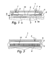
- figs. 1 and 2 depict an apparatus of the invention for heating glass sheets in preparation of tempering.
- the apparatus comprises a heating furnace, indicated with reference numeral 1.
- the heating furnace 1 has a longitudinal direction and a lateral direction.
- the heating furnace is provided with a conveyor 2, comprising e.g. rolls 2, which is capable of carrying glass sheets G in the longitudinal furnace direction.
- nozzle enclosures 6 whose downward facing side, a so-called nozzle deck 6a, is formed with jet orifices 9 (see also fig. 3 ) for blasting heated convection air towards the conveyor, and specifically towards a glass sheet G carried on the conveyor.
- the heating furnace 1 is provided with means 3-8.
- Such means for setting convection air in circulation include air ducts 3 above each nozzle enclosure 6 and in communication with the nozzle enclosures 6 by way of perforated plates 10.
- the air ducts 3 are in connection with transverse cross-furnace distribution channels 5, which are fitted with an air circulation fan 4 present inside the furnace.
- a drive motor 7 for the air circulation fan 4 is disposed outside the furnace 1.
- the nozzle enclosures 6 are provided with open resistors 8, across which the air delivered into the nozzle enclosure 6 finds its way further through the jet orifices 9 towards the rolls 2 and the glass sheet G.
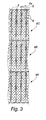
- FIG. 3 From fig. 3 can be seen an apparatus of the invention in one preferred embodiment.
- fig. 3 are seen in a view from below the nozzle enclosures 6 and the air ducts 3 disposed thereabove.
- each nozzle enclosure 6 is divided into successive enclosure segments 6A, 6B and 6C and each of these successive enclosure segments 6A, 6B, 6C is set at an acute angle ⁇ with respect to the glass traveling direction, resulting in a staggered configuration despite the fact that the enclosure segments are in alignment with each other in terms of the glass traveling direction.
- the above-mentioned angle ⁇ is preferably 2-10 degrees, most preferably about 3-5 degrees.
- the nozzle enclosure 6 it is not absolutely necessary to divide the nozzle enclosure 6 into enclosure segments, but it can be diverted to the above-mentioned angle ⁇ also as an undivided unit. In this case, however, the demand of space for the nozzle enclosures 6 increases in a lateral direction of the furnace 1 as compared to the embodiment of fig. 3 . It is obvious that by shortening the enclosure segmentation length, the angle can be broadened, even up to more than 10 degrees. Between diagonally directed enclosure segments can be present rectilinear enclosure segments or the directions of various enclosure segments may divert on either side of the traveling direction.
- the jet orifices 9 are disposed relative to a glass sheet in such positions that the hot air blasted onto the glass sheet G becomes more evenly distributed over the surface of the glass sheet 6 and the above-mentioned problems shall be substantially eliminated or at least mitigated.
Landscapes
- Chemical & Material Sciences (AREA)
- Engineering & Computer Science (AREA)
- Materials Engineering (AREA)
- Organic Chemistry (AREA)
- Physics & Mathematics (AREA)
- Thermal Sciences (AREA)
- Re-Forming, After-Treatment, Cutting And Transporting Of Glass Products (AREA)
Abstract
Description
- The present invention relates to an apparatus for heating glass sheets for tempering, said apparatus comprising:
- a heating furnace having a longitudinal direction and a lateral direction
- a conveyor in the furnace for carrying glass sheets in the longitudinal furnace direction
- means for circulating and heating convection air, said means comprising nozzle enclosures provided with jet orifices for blasting heated convection air towards the conveyor.
- There are prior known apparatuses of this type for heating glass sheets in preparation of tempering, wherein the air overlying a glass sheet is circulated in a space to be heated. Air is drawn in by fans inside the space from a top section of the furnace, followed by pressurizing and blowing the air further into nozzle enclosures set above the glass sheet. Inside the nozzle enclosures are open resistors, the air being blown across these and further through nozzle covers to a top surface of the glass. This is preceded, however, by blowing the air into an air duct, the position of which, with respect to the glass sheet, is above the nozzle enclosures. Between the air duct and the nozzle enclosure is a perforated plate capable of equalizing pressure differences before the air reaches the nozzle enclosure, in which the open resistor is also located.
- In currently available equipment, the nozzle enclosures are positioned in an almost longitudinal direction relative to the glass direction and at a distance of about 120 mm from each other. The jet orifices present in the nozzle deck are about 10 mm in diameter. In each nozzle deck, the orifices are typically arranged in three rows. Each row of orifices is spaced from the next one. The nozzle enclosure, including its open resistor, is about 2 meters in length. A problem with the foregoing type of equipment is anisotropy which occurs at the tempering stage. Anisotropy is a phenomenon, in which, prior to quenching (the glass temperature being 600-630°C), the glass has excessive temperature differences or the quenching produces temperature differences in the glass. In tempered glass, such a phenomenon is most easily observable e.g. in automotive rear window in the weather which is sunny, yet the sun is setting. This is when the rear window displays typically circular marks which are sometimes quite regular indeed. Such marks are the result of quenching.
- The phenomenon appears also whenever e.g. heat streaks are left on the glass by heating (resulting from the distance between adjacent rows of orifices), which then become visible during the quenching process or, at worst, accentuate even more the nozzle jet marks inflicted by quenching.
- It is an object of the present invention to reduce substantially or at least to minimize the foregoing problem with tempering furnaces. In other words, an object of the invention is to reduce in tempered glass the occurrence of anisotropy taking place during the course of tempering.
- The above-mentioned object of the invention is attained according to the present invention in such a way that the nozzle enclosures lengthwise of the furnace are disposed at an acute angle relative to the glass traveling direction, said angle being at least 2 degrees, preferably 2-10 degrees, most preferably about 3-5 degrees.
- The apparatus according to the invention enables avoiding the development of temperature differences in those parts of glass to be tempered which exist between nozzle enclosures or whose positions coincide with areas between the jet orifices of the nozzle enclosures, which are disposed in lengthwise rows. In other words, a result of diverting the nozzle enclosures is that there will be a presence of jet orifices in a cross-apparatus direction also at locations in which such orifices have thus far been non-existent. Consequently, the glass sheet heats up more consistently, which reduces the foregoing drawbacks.
- Preferred embodiments of the present invention are presented in the dependent claims.
- The invention will now be described more precisely with reference to the accompanying drawings, in which:
- Fig. 1
- shows an apparatus according to one preferred embodiment of the invention in a side view,
- fig. 2
- shows an apparatus according to the figure from the direction of an arrow 2 depicted in
fig. 1 , and - fig. 3
- shows nozzle enclosures and nozzle frames according to the embodiment of
fig. 1 in a view from below. - Hence,
figs. 1 and 2 depict an apparatus of the invention for heating glass sheets in preparation of tempering. The apparatus comprises a heating furnace, indicated with reference numeral 1. The heating furnace 1 has a longitudinal direction and a lateral direction. The heating furnace is provided with a conveyor 2, comprising e.g. rolls 2, which is capable of carrying glass sheets G in the longitudinal furnace direction. - Above the conveyor, preferably a short distance therefrom, e.g. 2-10 cm, preferably about 4 cm therefrom, are disposed
nozzle enclosures 6, whose downward facing side, a so-callednozzle deck 6a, is formed with jet orifices 9 (see alsofig. 3 ) for blasting heated convection air towards the conveyor, and specifically towards a glass sheet G carried on the conveyor. - In order to circulate the convection air blasted to the glass sheet G, the heating furnace 1 is provided with means 3-8. Such means for setting convection air in circulation include
air ducts 3 above eachnozzle enclosure 6 and in communication with thenozzle enclosures 6 by way of perforatedplates 10. Theair ducts 3 are in connection with transversecross-furnace distribution channels 5, which are fitted with anair circulation fan 4 present inside the furnace. Adrive motor 7 for theair circulation fan 4 is disposed outside the furnace 1. - The
nozzle enclosures 6 are provided withopen resistors 8, across which the air delivered into thenozzle enclosure 6 finds its way further through thejet orifices 9 towards the rolls 2 and the glass sheet G. - From
fig. 3 can be seen an apparatus of the invention in one preferred embodiment. Infig. 3 are seen in a view from below thenozzle enclosures 6 and theair ducts 3 disposed thereabove. Here, eachnozzle enclosure 6 is divided intosuccessive enclosure segments successive enclosure segments nozzle enclosure 6 into enclosure segments, but it can be diverted to the above-mentioned angle α also as an undivided unit. In this case, however, the demand of space for thenozzle enclosures 6 increases in a lateral direction of the furnace 1 as compared to the embodiment offig. 3 . It is obvious that by shortening the enclosure segmentation length, the angle can be broadened, even up to more than 10 degrees. Between diagonally directed enclosure segments can be present rectilinear enclosure segments or the directions of various enclosure segments may divert on either side of the traveling direction. - In an apparatus of the invention, the
jet orifices 9 are disposed relative to a glass sheet in such positions that the hot air blasted onto the glass sheet G becomes more evenly distributed over the surface of theglass sheet 6 and the above-mentioned problems shall be substantially eliminated or at least mitigated. - The present invention is not limited to just to the presented embodiment, but it finds a multitude of applications within the scope of protection defined by the claims.
Claims (5)
- An apparatus for heating glass sheets for tempering, said apparatus comprising:- a heating furnace (1) having a longitudinal direction and a lateral direction- a conveyor (2) in the furnace for carrying glass sheets (G) in the longitudinal furnace direction- means (3-8) for circulating and heating convection air, said means including nozzle enclosures (6) provided with jet orifices (9) for blasting heated convection air towards the conveyor, characterized in that the nozzle enclosures (6) lengthwise of the furnace are disposed at an acute angle relative to the glass traveling direction, said angle being at least 2 degrees, preferably 2-10 degrees, most preferably about 3-5 degrees.
- An apparatus as set forth in claim 1, characterized in that the nozzle enclosures (6) are divided into successive enclosure segments (6A, 6B, 6C), each of which is individually disposed in a staggered fashion at said small angle relative to the glass traveling direction.
- An apparatus as set forth in claim 1-2, characterized in that convection air heating elements (8) are located in the nozzle enclosures (6).
- An apparatus as set forth in claim 1-3, characterized in that the means for setting convection air in circulation include air ducts (3) above each nozzle enclosure (6) and in communication with the nozzle enclosures (6) by way of perforated plates (10).
- An apparatus as set forth in claim 1-4, characterized in that the air ducts (3) are in connection with transverse cross-furnace distribution channels (5), which are fitted with an air circulation fan (4) present inside the furnace (1).
Applications Claiming Priority (1)
| Application Number | Priority Date | Filing Date | Title |
|---|---|---|---|
| FI20105257A FI20105257A7 (en) | 2010-03-15 | 2010-03-15 | Apparatus for heating glass sheets for tempering |
Publications (2)
| Publication Number | Publication Date |
|---|---|
| EP2368855A2 true EP2368855A2 (en) | 2011-09-28 |
| EP2368855A3 EP2368855A3 (en) | 2012-10-10 |
Family
ID=42074370
Family Applications (1)
| Application Number | Title | Priority Date | Filing Date |
|---|---|---|---|
| EP11153994A Withdrawn EP2368855A3 (en) | 2010-03-15 | 2011-02-10 | Apparatus for heating glass sheets for tempering |
Country Status (4)
| Country | Link |
|---|---|
| US (1) | US20110219822A1 (en) |
| EP (1) | EP2368855A3 (en) |
| CN (1) | CN102190433A (en) |
| FI (1) | FI20105257A7 (en) |
Cited By (3)
| Publication number | Priority date | Publication date | Assignee | Title |
|---|---|---|---|---|
| EP2805927A1 (en) * | 2013-05-23 | 2014-11-26 | TaiFin Glass Machinery Oy | Glass tempering furnace |
| EP2805926B1 (en) | 2013-05-23 | 2016-12-21 | TaiFin Glass Machinery Oy | Glass tempering furnace and method for heating glass sheets |
| WO2020188147A1 (en) * | 2019-03-21 | 2020-09-24 | Glaston Finland Oy | Tempering furnace for glass sheets |
Families Citing this family (3)
| Publication number | Priority date | Publication date | Assignee | Title |
|---|---|---|---|---|
| WO2019002672A1 (en) * | 2017-06-27 | 2019-01-03 | Glaston Finland Oy | Method for tempering glass sheets |
| FI129544B (en) * | 2019-07-03 | 2022-04-14 | Glaston Finland Oy | Tempering furnace for glass sheets |
| CN111099816A (en) * | 2020-01-13 | 2020-05-05 | 洛阳德勤机械设备有限公司 | Forced convection method and device for toughened glass heating furnace |
Citations (2)
| Publication number | Priority date | Publication date | Assignee | Title |
|---|---|---|---|---|
| JP2005097033A (en) | 2003-09-24 | 2005-04-14 | Asahi Glass Co Ltd | Heating method for plate |
| CN1861535A (en) | 2006-03-08 | 2006-11-15 | 姚敏 | Energy saving strong convection sheet glass heating oven |
Family Cites Families (10)
| Publication number | Priority date | Publication date | Assignee | Title |
|---|---|---|---|---|
| US3223499A (en) * | 1962-06-04 | 1965-12-14 | Pittsburgh Plate Glass Co | Method of treating and conveying glass sheets |
| US3293015A (en) * | 1961-09-22 | 1966-12-20 | Pittsburgh Plate Glass Co | Method and apparatus for tempering glass sheets on a gas support bed |
| US3332759A (en) * | 1963-11-29 | 1967-07-25 | Permaglass | Method of and apparatus for manufacturing glass sheets on a gas support bed |
| US4178414A (en) * | 1977-06-23 | 1979-12-11 | Triplex Safety Glass Company Limited | Method of toughening glass sheets |
| US4157910A (en) * | 1978-01-24 | 1979-06-12 | Ppg Industries, Inc. | Apparatus for tempering flat or curved glass sheets |
| US4200446A (en) * | 1979-01-29 | 1980-04-29 | Ppg Industries, Inc. | Gas hearth electrical heating supplement and method of operation |
| JP2001026434A (en) * | 1999-07-13 | 2001-01-30 | Nippon Sheet Glass Co Ltd | Glass quenching equipment |
| FI109292B (en) * | 1999-11-01 | 2002-06-28 | Uniglass Engineering Oy | Method and apparatus for heating glass |
| JP4680395B2 (en) * | 2001-01-24 | 2011-05-11 | 日本板硝子株式会社 | Sheet glass bending apparatus and sheet glass bending method |
| FI126760B (en) * | 2010-01-11 | 2017-05-15 | Glaston Services Ltd Oy | Method and apparatus for supporting glass sheets and heating them with hot gas pad |
-
2010
- 2010-03-15 FI FI20105257A patent/FI20105257A7/en not_active IP Right Cessation
-
2011
- 2011-02-10 EP EP11153994A patent/EP2368855A3/en not_active Withdrawn
- 2011-03-07 US US13/041,824 patent/US20110219822A1/en not_active Abandoned
- 2011-03-15 CN CN201110061601XA patent/CN102190433A/en active Pending
Patent Citations (2)
| Publication number | Priority date | Publication date | Assignee | Title |
|---|---|---|---|---|
| JP2005097033A (en) | 2003-09-24 | 2005-04-14 | Asahi Glass Co Ltd | Heating method for plate |
| CN1861535A (en) | 2006-03-08 | 2006-11-15 | 姚敏 | Energy saving strong convection sheet glass heating oven |
Cited By (6)
| Publication number | Priority date | Publication date | Assignee | Title |
|---|---|---|---|---|
| EP2805927A1 (en) * | 2013-05-23 | 2014-11-26 | TaiFin Glass Machinery Oy | Glass tempering furnace |
| US9422183B2 (en) | 2013-05-23 | 2016-08-23 | Taifin Glass Machinery Oy | Glass tempering furnace |
| EP2805926B1 (en) | 2013-05-23 | 2016-12-21 | TaiFin Glass Machinery Oy | Glass tempering furnace and method for heating glass sheets |
| WO2020188147A1 (en) * | 2019-03-21 | 2020-09-24 | Glaston Finland Oy | Tempering furnace for glass sheets |
| US11852413B2 (en) | 2019-03-21 | 2023-12-26 | Glaston Finland Oy | Tempering furnace for glass sheets |
| EP3941883B1 (en) * | 2019-03-21 | 2025-10-29 | Glaston Finland Oy | Tempering furnace for glass sheets |
Also Published As
| Publication number | Publication date |
|---|---|
| FI20105257L (en) | 2011-09-16 |
| EP2368855A3 (en) | 2012-10-10 |
| FI20105257A7 (en) | 2011-09-16 |
| FI20105257A0 (en) | 2010-03-15 |
| CN102190433A (en) | 2011-09-21 |
| US20110219822A1 (en) | 2011-09-15 |
Similar Documents
| Publication | Publication Date | Title |
|---|---|---|
| US20110219822A1 (en) | Apparatus for heating glass sheets for tempering | |
| US6470711B1 (en) | Furnace for heat treatments of glass sheets | |
| PL206430B1 (en) | System and method for simultaneously meating and cooling glass to produce tempered glass | |
| TWI850351B (en) | Tempering furnace for glass sheets | |
| EP2805926B1 (en) | Glass tempering furnace and method for heating glass sheets | |
| CN101223113A (en) | Flat glass stove | |
| EP3994103B1 (en) | Tempering furnace for a glass sheet and a method for heating a glass sheet for tempering | |
| TW201808838A (en) | Method and apparatus for tempering glass sheets | |
| EP1626938B1 (en) | Method and furnace for bending glass panels | |
| CN100593021C (en) | Convection Furnaces for Tempering Glass Sheets | |
| EP2805927B1 (en) | Glass tempering furnace | |
| EP1648835B1 (en) | Method for observing a glass and controlling heating effect in a hardening oven for a glass sheet | |
| EP0416332A1 (en) | Method and apparatus for preventing the arching of glass sheets in the roller-equipped furnace of a horizontal tempering plant | |
| JP2010234383A (en) | Method of cooling ring-like hot-rolled wire rod and apparatus therefor | |
| EP2433912B1 (en) | Nozzle housing assembly | |
| FI111006B (en) | Heat conducting method of glass sheet, involves blowing air sucked for suction chamber into pressure chamber from which air flows on glass | |
| CN101868427B (en) | Apparatus and method for blowing fluid onto the surface of thin glass components | |
| FI127879B (en) | Device for tempering planar glass sheets | |
| FI20215179A1 (en) | Tempering furnace for glass sheets |
Legal Events
| Date | Code | Title | Description |
|---|---|---|---|
| PUAI | Public reference made under article 153(3) epc to a published international application that has entered the european phase |
Free format text: ORIGINAL CODE: 0009012 |
|
| AK | Designated contracting states |
Kind code of ref document: A2 Designated state(s): AL AT BE BG CH CY CZ DE DK EE ES FI FR GB GR HR HU IE IS IT LI LT LU LV MC MK MT NL NO PL PT RO RS SE SI SK SM TR |
|
| AX | Request for extension of the european patent |
Extension state: BA ME |
|
| TPAC | Observations by third parties |
Free format text: ORIGINAL CODE: EPIDOSNTIPA |
|
| PUAL | Search report despatched |
Free format text: ORIGINAL CODE: 0009013 |
|
| AK | Designated contracting states |
Kind code of ref document: A3 Designated state(s): AL AT BE BG CH CY CZ DE DK EE ES FI FR GB GR HR HU IE IS IT LI LT LU LV MC MK MT NL NO PL PT RO RS SE SI SK SM TR |
|
| AX | Request for extension of the european patent |
Extension state: BA ME |
|
| RIC1 | Information provided on ipc code assigned before grant |
Ipc: C03B 29/08 20060101AFI20120831BHEP |
|
| STAA | Information on the status of an ep patent application or granted ep patent |
Free format text: STATUS: THE APPLICATION IS DEEMED TO BE WITHDRAWN |
|
| 18D | Application deemed to be withdrawn |
Effective date: 20130411 |