EP2368794A2 - Aircraft slat disconnect sensor - Google Patents
Aircraft slat disconnect sensor Download PDFInfo
- Publication number
- EP2368794A2 EP2368794A2 EP11250338A EP11250338A EP2368794A2 EP 2368794 A2 EP2368794 A2 EP 2368794A2 EP 11250338 A EP11250338 A EP 11250338A EP 11250338 A EP11250338 A EP 11250338A EP 2368794 A2 EP2368794 A2 EP 2368794A2
- Authority
- EP
- European Patent Office
- Prior art keywords
- arms
- fuse
- slat
- sensor according
- disconnect
- Prior art date
- Legal status (The legal status is an assumption and is not a legal conclusion. Google has not performed a legal analysis and makes no representation as to the accuracy of the status listed.)
- Withdrawn
Links
- 239000012212 insulator Substances 0.000 claims description 10
- 238000004519 manufacturing process Methods 0.000 claims 1
- 239000004696 Poly ether ether ketone Substances 0.000 description 2
- JUPQTSLXMOCDHR-UHFFFAOYSA-N benzene-1,4-diol;bis(4-fluorophenyl)methanone Chemical compound OC1=CC=C(O)C=C1.C1=CC(F)=CC=C1C(=O)C1=CC=C(F)C=C1 JUPQTSLXMOCDHR-UHFFFAOYSA-N 0.000 description 2
- 238000009413 insulation Methods 0.000 description 2
- 229920002530 polyetherether ketone Polymers 0.000 description 2
- 235000014676 Phragmites communis Nutrition 0.000 description 1
- 239000012774 insulation material Substances 0.000 description 1
- 239000000463 material Substances 0.000 description 1
- 239000002184 metal Substances 0.000 description 1
- 230000004048 modification Effects 0.000 description 1
- 238000012986 modification Methods 0.000 description 1
Images




Classifications
-
- B—PERFORMING OPERATIONS; TRANSPORTING
- B64—AIRCRAFT; AVIATION; COSMONAUTICS
- B64C—AEROPLANES; HELICOPTERS
- B64C9/00—Adjustable control surfaces or members, e.g. rudders
- B64C9/14—Adjustable control surfaces or members, e.g. rudders forming slots
- B64C9/16—Adjustable control surfaces or members, e.g. rudders forming slots at the rear of the wing
- B64C9/18—Adjustable control surfaces or members, e.g. rudders forming slots at the rear of the wing by single flaps
-
- B—PERFORMING OPERATIONS; TRANSPORTING
- B64—AIRCRAFT; AVIATION; COSMONAUTICS
- B64D—EQUIPMENT FOR FITTING IN OR TO AIRCRAFT; FLIGHT SUITS; PARACHUTES; ARRANGEMENT OR MOUNTING OF POWER PLANTS OR PROPULSION TRANSMISSIONS IN AIRCRAFT
- B64D45/00—Aircraft indicators or protectors not otherwise provided for
- B64D45/0005—Devices specially adapted to indicate the position of a movable element of the aircraft, e.g. landing gear
-
- B—PERFORMING OPERATIONS; TRANSPORTING
- B64—AIRCRAFT; AVIATION; COSMONAUTICS
- B64D—EQUIPMENT FOR FITTING IN OR TO AIRCRAFT; FLIGHT SUITS; PARACHUTES; ARRANGEMENT OR MOUNTING OF POWER PLANTS OR PROPULSION TRANSMISSIONS IN AIRCRAFT
- B64D45/00—Aircraft indicators or protectors not otherwise provided for
- B64D45/0005—Devices specially adapted to indicate the position of a movable element of the aircraft, e.g. landing gear
- B64D2045/001—Devices specially adapted to indicate the position of a movable element of the aircraft, e.g. landing gear for indicating symmetry of flaps deflection
-
- Y—GENERAL TAGGING OF NEW TECHNOLOGICAL DEVELOPMENTS; GENERAL TAGGING OF CROSS-SECTIONAL TECHNOLOGIES SPANNING OVER SEVERAL SECTIONS OF THE IPC; TECHNICAL SUBJECTS COVERED BY FORMER USPC CROSS-REFERENCE ART COLLECTIONS [XRACs] AND DIGESTS
- Y10—TECHNICAL SUBJECTS COVERED BY FORMER USPC
- Y10T—TECHNICAL SUBJECTS COVERED BY FORMER US CLASSIFICATION
- Y10T29/00—Metal working
- Y10T29/49—Method of mechanical manufacture
- Y10T29/49002—Electrical device making
- Y10T29/49227—Insulator making
Definitions
- This disclosure relates to a slat disconnect sensor for use in aircraft airfoil applications.
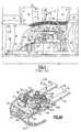
- the underside of a prior art slat 16 with a disconnect sensor 32 is shown in Figure 1 , and which is also described in United States Patent No. 6,483;436 .
- the disconnect sensor 32 includes first and second arms 36, 38 that straddle a striker pin 34 provided on one of the slat sections 28.
- the first and second arms 36, 38 are supported for pivotal movement about pivots 42 and are supported on a bracket 40 mounted to one of the slat sections 28.
- a spring 44 is provided between the first and second arms 36, 38 to bias the arms apart from one another during the disconnect condition.
- a disconnect condition occurs when the adjoining slat sections 28 move relative to one another causing the striker pin 34 to engage and apply a load to one of the first and second arms 36, 38.
- a mechanical link 46 includes opposing ends secured to each of the first and second arms 36, 38 by fasteners 48. When a sufficient amount of force has been applied by the striker pin 34 to one of the first and second arms 36, 38, the mechanical link 46 will fracture at a weakened area along the mechanical link 46, enabling the first and second arms 36 38 to move apart from one another about their respective pivots 42. The spring 44 keeps the first and second arms 36, 38 apart from one another when the mechanical link 46 has broken.
- the first arm 36 supports a magnet 50 that is adjacent to an end 52 of the second arm 38.
- the end 52 supports a sensor 54, such as a Reed switch, that acts as a proximity sensor to detect the proximity of the magnet 50.
- the magnet 50 moves out of alignment with the sensor 54, which sends a signal via wires 56 connected to a controller via a harness 58 to indicate that the slat sections 28 have moved undesirably relative to one another, indicating a failure in the airfoil surface control system 12.
- a slat disconnect sensor includes a base. First and second arms are spaced apart from one another and are operatively supported by the base. At least one of the first and second arms have an end mounted to the base and is rotatable relative thereto at a pivot between connect and disconnect conditions.
- a mechanical link includes first and second link portions respectively secured to the first and second arms. The link interconnects the first and second arms and includes a weakened area providing a frangible connection in the connect condition and is configured to break at the frangible connection in the disconnect condition.
- a fuse includes first and second fuse portions operatively mounted to the first and second arms. The fuse is interconnected between the first and second arms to provide continuity in the connected condition, and continuity is broken between the first and second portions in the disconnect condition.
- the mechanical link and the fuse are the same, and the fuse is insulated from the first and second arms. In another example, the mechanical link and fuse are different from one another and spaced apart along from one another on the arms.
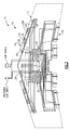
- FIG. 2 An aircraft 10 is depicted in a highly schematic fashion in Figure 2 .
- the aircraft 10 includes an airfoil surface control system 12 (a portion of which is also depicted in Figure 3 ) for a wing 14 under the aircraft 10.
- the wing 14 includes slats ' 16 and flaps 18 that are actuated using drivers 22 and actuators 24 that are commanded by controllers 20.
- One or more gear boxes 26 may be provided between the drivers 22 and actuators 24.
- the slats 16 include multiple slat sections 28 that are arranged adjacent to one another at joints 30 so that the slat sections 28 move in unison with one another in response to an input.
- one or more of the slat sections 28 may become jammed and, thus, the slats 16 are designed such that the slat sections 28 can be moved independently from one another so that complete control of the airfoil surface is not lost.
- one or more disconnect sensors 32 are arranged to detect the relative movement of slat sections 28 from a connect condition to a disconnect condition as a result of this undesired condition.
- the disconnect sensors 32 communicate a loss of electrical continuity-in the disconnect condition in the example.
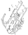
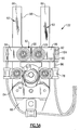
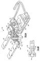
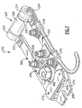
- a first example disconnect sensor 132 is illustrated in Figures 4A-6A .
- the disconnect sensor 132 includes first and second arms 60, 62 pivotally supported by first ends 64, which provide holes 70.
- a base 68 having a pivot 72 for each of the first and second arms 60, 62 supports the first ends 64. Although both arms pivot in the example, another arrangement may only include one pivoting arm.
- a spring 74 is supported by the base 68 and arranged between the first and second arms 60, 62. Other biasing means may be used, for example, the spring may be integrated into one of the arms.
- a lug 76 is supported on the base 68 and provides an aperture that may be used to secure the disconnect sensor 132 to the bracket 40 (not shown).
- the first and second arms 60, 62 include second ends 66 opposite the first ends 64 that provide surfaces 98, which may engage with the striker pin 34 (shown in Figure 1 ) during a disconnect condition.
- a pair of fuses 82 serve not only as a mechanical link but also as an electrical switch or fuse. While a pair of fuses 82 is illustrated, it should be understood that one or more fuses may be used. Using multiple fuses enables redundancy such that the electrical continuity state of the fuses can be communicated to the controller(s) over multiple channels, such as by using the configuration illustrated in Figure 3 .
- the fuse 82 includes first and second portions 84, 86 secured to first and second arms 60, 62 respectively by a fastener 106 and interconnected by a neck 88 that provides frangible connection or weakened area that breaks during a disconnect condition. Each fastener 106 includes a stud and a nut in the example.
- Wires 94 are connected to both of the first and second portions 84, 86 such that when the fuse 82 breaks at the neck 88, continuity is lost between the wires 94, which indicates that a disconnect condition has occurred.
- Clips 78 and fasteners 80 are used to support the wires 94 at various locations.
- Ends of the first and second portions 84, 86 include first and second crimps 90, 92 that respectively crimps the bare wire and wire insulation 96 of the wires 94 to provide the mechanical and electrical connection between the wires 94 and the fuse 82.
- the base 68 may extend in a manner so as to provide a bracket (not shown) that supports an electrical connector (not shown) connected to the wires 94.
- the fuses 82 must be insulated from the first and second arms 60, 62.
- the fuses 82, fasteners 106 and first and second arms 60, 62 are metal. Although threaded fasteners are illustrated, other fasteners, such as rivets, may be used.
- first, second and third insulators 100, 102, 104 are used to electrically insulate the fuses 82 and the fasteners 106 used to secure the first and second portions 84, 86 to the arms 60, 62 from one another. To ensure proper assembly of the disconnect sensor 132 and sufficient insulation various nesting locating features are used.
- the first insulator 100 includes a first collar 108 that is in close proximity to the fastener 106.
- the second insulator 102 includes a second collar 110 that is coaxial and in engagement with the first collar 108.
- the third insulator 104 includes a diameter 112 that is sufficient to accommodate the diameters of the first and second collars 108, 110.
- the first insulator 100 may be provided by two discreet sections with adjacent ends.
- the third insulator 104 is also illustrated as being provided by two discreet sections, however, they include a lapped joint 114 where the adjacent ends of the third insulator 104 meet.
- Another example sensor 132 shown in Figure 6B , includes a fuse 182 encapsulated in an insulation material 101, such as PEEK.
- PEEK is the same material used to insulate the wires 194.
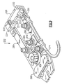
- FIG. 7-9 Another disconnect sensor 232 is illustrated in Figures 7-9 . Like numerals are used to indicate like elements.
- the disconnect sensor 232 is similar to the disconnect sensor 132 except that a mechanical link 246 is discreet from an electrical sensor 226, which senses the disconnect condition when the first and second arms 260, 262 have fractured the weakened area of the mechanical link 246.
- a holder 224 is mounted on each one of the first and second arms 260, 262 via fasteners (not shown) that are received in apertures 220, 222 respectively provided in the first and second arms 260, 262 and the holders 224.
- the sensor 226 includes first and second portions 228, 230 that are respectively secured to a holder 224.
- the first and second portions 228, 230 include pins 231 and receptacles 233, for example, schematically illustrated in Figure 9 , that cooperate to electrically engage with one another to maintain continuity while the slat sections 28 move in unison with one another.
- the second portion 230 is pulled out of the first portion 228, which breaks electrical continuity between the pins 231 and the receptacles 233.
Landscapes
- Engineering & Computer Science (AREA)
- Aviation & Aerospace Engineering (AREA)
- Fuses (AREA)
- Details Of Connecting Devices For Male And Female Coupling (AREA)
Abstract
A slat disconnect sensor (32;32;232) includes a base (68). First and second arms (60,62;260,262) are spaced apart from one another and are operatively supported by the base. (68) At least one of the first and second arms have an end (64) mounted to the base and is rotatable relative thereto at a pivot (72) between connect and disconnect conditions. A mechanical link (82;246) includes first and second link portions (84,86) respectively secured to the first and second arms. The link interconnects the first and second arms and includes a weakened area (88) providing a frangible connection in the connect condition and is configured to break at the frangible connection in the disconnect condition. A fuse (82;182;226) includes first and second fuse portions (84,86;228,230) operatively mounted to the first and second arms. The fuse is interconnected between the first and second arms providing continuity in the connected condition, and continuity is broken between the first and second portions in the disconnect condition.
Description
- This disclosure relates to a slat disconnect sensor for use in aircraft airfoil applications.
- The underside of a
prior art slat 16 with adisconnect sensor 32 is shown inFigure 1 , and which is also described in United States Patent No.6,483;436 . Thedisconnect sensor 32 includes first andsecond arms striker pin 34 provided on one of theslat sections 28. The first andsecond arms pivots 42 and are supported on abracket 40 mounted to one of theslat sections 28. Aspring 44 is provided between the first andsecond arms - A disconnect condition occurs when the adjoining
slat sections 28 move relative to one another causing thestriker pin 34 to engage and apply a load to one of the first andsecond arms mechanical link 46 includes opposing ends secured to each of the first andsecond arms fasteners 48. When a sufficient amount of force has been applied by thestriker pin 34 to one of the first andsecond arms mechanical link 46 will fracture at a weakened area along themechanical link 46, enabling the first andsecond arms 36 38 to move apart from one another about theirrespective pivots 42. Thespring 44 keeps the first andsecond arms mechanical link 46 has broken. - In the example shown, the
first arm 36 supports amagnet 50 that is adjacent to anend 52 of thesecond arm 38. Theend 52 supports asensor 54, such as a Reed switch, that acts as a proximity sensor to detect the proximity of themagnet 50. During the disconnect condition, themagnet 50 moves out of alignment with thesensor 54, which sends a signal viawires 56 connected to a controller via aharness 58 to indicate that theslat sections 28 have moved undesirably relative to one another, indicating a failure in the airfoilsurface control system 12. - A slat disconnect sensor includes a base. First and second arms are spaced apart from one another and are operatively supported by the base. At least one of the first and second arms have an end mounted to the base and is rotatable relative thereto at a pivot between connect and disconnect conditions. A mechanical link includes first and second link portions respectively secured to the first and second arms. The link interconnects the first and second arms and includes a weakened area providing a frangible connection in the connect condition and is configured to break at the frangible connection in the disconnect condition. A fuse includes first and second fuse portions operatively mounted to the first and second arms. The fuse is interconnected between the first and second arms to provide continuity in the connected condition, and continuity is broken between the first and second portions in the disconnect condition.
- In one example, the mechanical link and the fuse are the same, and the fuse is insulated from the first and second arms. In another example, the mechanical link and fuse are different from one another and spaced apart along from one another on the arms.
- The disclosure can be further understood by reference to the following detailed description when considered in connection with the accompanying drawings wherein:
-
Figure 1 is a schematic view of a prior art slat disconnect system. -
Figure 2 is a schematic of an airfoil surface control system. -
Figure 3 is a schematic of a portion of the airfoil surface control system shown inFigure 2 . -
Figures 4A and4B are perspective top and bottom views, respectively, of a first slat disconnect sensor. -
Figures 5A and5B are top and side elevational views, respectively, of the first slat disconnect sensor. -
Figure 6A is a partial cross-sectional view of the first slat disconnect sensor. -
Figure 6B is a partial cross-sectional view of another example fuse for the first slat disconnect sensor. -
Figure 7 is a top perspective view of a second slat disconnect sensor. -
Figures 8A and8B are top and side elevational views, respectively, of the second slat disconnect sensor. -
Figure 9 is a partial cross-sectional perspective view of the second slat disconnect sensor. - An
aircraft 10 is depicted in a highly schematic fashion inFigure 2 . Theaircraft 10 includes an airfoil surface control system 12 (a portion of which is also depicted inFigure 3 ) for awing 14 under theaircraft 10. Thewing 14 includes slats ' 16 andflaps 18 that are actuated using drivers 22 andactuators 24 that are commanded bycontrollers 20. One ormore gear boxes 26 may be provided between the drivers 22 andactuators 24. - The
slats 16 include multipleslat sections 28 that are arranged adjacent to one another atjoints 30 so that theslat sections 28 move in unison with one another in response to an input. During an undesired condition, one or more of theslat sections 28 may become jammed and, thus, theslats 16 are designed such that theslat sections 28 can be moved independently from one another so that complete control of the airfoil surface is not lost. To this end, one or moredisconnect sensors 32 are arranged to detect the relative movement ofslat sections 28 from a connect condition to a disconnect condition as a result of this undesired condition. Thedisconnect sensors 32 communicate a loss of electrical continuity-in the disconnect condition in the example. - A first
example disconnect sensor 132 is illustrated inFigures 4A-6A . Thedisconnect sensor 132 includes first andsecond arms first ends 64, which provideholes 70. Abase 68 having apivot 72 for each of the first andsecond arms first ends 64. Although both arms pivot in the example, another arrangement may only include one pivoting arm. Aspring 74 is supported by thebase 68 and arranged between the first andsecond arms lug 76 is supported on thebase 68 and provides an aperture that may be used to secure thedisconnect sensor 132 to the bracket 40 (not shown). The first andsecond arms second ends 66 opposite thefirst ends 64 that providesurfaces 98, which may engage with the striker pin 34 (shown inFigure 1 ) during a disconnect condition. - With the
disconnect sensor 132, a pair offuses 82 serve not only as a mechanical link but also as an electrical switch or fuse. While a pair offuses 82 is illustrated, it should be understood that one or more fuses may be used. Using multiple fuses enables redundancy such that the electrical continuity state of the fuses can be communicated to the controller(s) over multiple channels, such as by using the configuration illustrated inFigure 3 . Thefuse 82 includes first andsecond portions second arms fastener 106 and interconnected by aneck 88 that provides frangible connection or weakened area that breaks during a disconnect condition. Eachfastener 106 includes a stud and a nut in the example. -
Wires 94 are connected to both of the first andsecond portions fuse 82 breaks at theneck 88, continuity is lost between thewires 94, which indicates that a disconnect condition has occurred.Clips 78 and fasteners 80 are used to support thewires 94 at various locations. Ends of the first andsecond portions second crimps wire insulation 96 of thewires 94 to provide the mechanical and electrical connection between thewires 94 and thefuse 82. Thebase 68 may extend in a manner so as to provide a bracket (not shown) that supports an electrical connector (not shown) connected to thewires 94. - The
fuses 82 must be insulated from the first andsecond arms fuses 82,fasteners 106 and first andsecond arms third insulators Figure 6A ) are used to electrically insulate thefuses 82 and thefasteners 106 used to secure the first andsecond portions arms disconnect sensor 132 and sufficient insulation various nesting locating features are used. Thefirst insulator 100 includes afirst collar 108 that is in close proximity to thefastener 106. Thesecond insulator 102 includes a second collar 110 that is coaxial and in engagement with thefirst collar 108. Thethird insulator 104 includes adiameter 112 that is sufficient to accommodate the diameters of the first andsecond collars 108, 110. As illustrated inFigure 4B , thefirst insulator 100 may be provided by two discreet sections with adjacent ends. Thethird insulator 104 is also illustrated as being provided by two discreet sections, however, they include a lapped joint 114 where the adjacent ends of thethird insulator 104 meet. - Another
example sensor 132, shown inFigure 6B , includes afuse 182 encapsulated in aninsulation material 101, such as PEEK. Thus, the need for discrete insulating members can be eliminated. In one example, PEEK is the same material used to insulate thewires 194. - Another
disconnect sensor 232 is illustrated inFigures 7-9 . Like numerals are used to indicate like elements. Thedisconnect sensor 232 is similar to thedisconnect sensor 132 except that amechanical link 246 is discreet from anelectrical sensor 226, which senses the disconnect condition when the first andsecond arms mechanical link 246. Aholder 224 is mounted on each one of the first andsecond arms apertures second arms holders 224. - The
sensor 226 includes first andsecond portions holder 224. The first andsecond portions pins 231 andreceptacles 233, for example, schematically illustrated inFigure 9 , that cooperate to electrically engage with one another to maintain continuity while theslat sections 28 move in unison with one another. During a disconnect condition thesecond portion 230 is pulled out of thefirst portion 228, which breaks electrical continuity between thepins 231 and thereceptacles 233. - Although example embodiments have been disclosed, a worker of ordinary skill in this art would recognize that certain modifications would come within the scope of the claims. For that reason, the following claims should be studied to determine their true scope and content.
Claims (15)
- A slat disconnect sensor (32; 132;232) comprising:a base (68);first and second arms (60,62;260,262) spaced apart from one another and operatively supported by the base, at least one of the first and second arms having an end (64) mounted to the base and rotatable relative thereto at a pivot (72) between connect and disconnect conditions;a mechanical link (82;246) including first and second link portions (84,86) respectively secured to the first and second arms, the link interconnecting the first and second arms and including a weakened area (88) providing a frangible connection in the connect condition and being configured to break at the frangible connection in the disconnect condition; anda fuse (82;182;226) including first and second fuse portions (84,86;228,230) operatively mounted to the first and second arms, the fuse being interconnected between the first and second arms providing continuity in the connected condition, continuity being broken between the first and second fuse portions in the disconnect condition.
- The slat disconnect sensor according to claim 1, wherein the first and second fuse portions (84,86) are respectively the same as the first and second link portions (84,86).
- The slat disconnect sensor according to claim 2, comprising first and second wires (94;194) electrically connected respectively to the first and second fuse portions (84,86) with the link (82) providing continuity between the first and second wires (94) in the connected condition, continuity being broken between the first and second wires in the disconnect condition.
- The slat disconnect sensor according to claim 3, wherein the first and second portions (84,86) provide crimps (90,92) about the first and second wires.
- The slat disconnect sensor according to claim 2, comprising a pair of mechanical links (82) providing a pair of fuses (82) corresponding to first and second channels.
- The slat disconnect sensor according to claim 2, wherein each of the first and second fuse portions (84,86) are secured to the first and second arms (60,62) respectively by a fastener (106).
- The slat disconnect sensor according to claim 6, wherein the fuse (82) is insulated from the first and second arms (60,62).
- The slat disconnect sensor according to claim 7, comprising first and second insulators (100,102) are respectively provided on opposing sides of the fuse (82) and between the fuse and each fastener (106).
- The slat disconnect sensor according to claim 8, wherein the first and second insulators (100,102) are nested relative to one another.
- The slat disconnect sensor according to claim 9, comprising a pair of mechanical links (82) providing a pair of fuses (82) corresponding to first and second channels, and a third insulator (104) provided between the fuses.
- The slat disconnect sensor according to any preceding claim, wherein the first and second arms (60,62) are symmetrical with one another.
- The slat disconnect sensor according to claim 1, wherein the mechanical link (246) is spaced from the fuse (226) along the first and second arms (260,262).
- The slat disconnect sensor according to claim 12, wherein the first and second fuse portions (228,230) respectively correspond to a pin (231) and a receptacle (233) that engagingly cooperate with one another to maintain continuity receptacle (233) that engagingly cooperate with one another to maintain continuity in the connect condition.
- The slat disconnect sensor according to claim 13, wherein the mechanical link (82) is in engagement with the first and second arms (260,262).
- A method of manufacturing a slat disconnect sensor (32;132;232) comprising:providing spaced apart arms (60,62;260,262) pivotally supported relative to a base (68);securing a link (82;246) between the arms;providing a weakened area (88) in the linkinsulating the link from the arms;providing a fuse (82;182;262);securing the fuse between the spaced apart arms; andproviding continuity across the fuse in a connect condition.
Applications Claiming Priority (2)
| Application Number | Priority Date | Filing Date | Title |
|---|---|---|---|
| US31700810P | 2010-03-24 | 2010-03-24 | |
| US12/890,769 US8516898B2 (en) | 2010-03-24 | 2010-09-27 | Aircraft slat disconnect sensor |
Publications (1)
| Publication Number | Publication Date |
|---|---|
| EP2368794A2 true EP2368794A2 (en) | 2011-09-28 |
Family
ID=44166488
Family Applications (1)
| Application Number | Title | Priority Date | Filing Date |
|---|---|---|---|
| EP11250338A Withdrawn EP2368794A2 (en) | 2010-03-24 | 2011-03-18 | Aircraft slat disconnect sensor |
Country Status (2)
| Country | Link |
|---|---|
| US (1) | US8516898B2 (en) |
| EP (1) | EP2368794A2 (en) |
Cited By (2)
| Publication number | Priority date | Publication date | Assignee | Title |
|---|---|---|---|---|
| EP3006344A1 (en) * | 2014-10-09 | 2016-04-13 | Hamilton Sundstrand Corporation | Differential motion sensor |
| EP3025966A1 (en) * | 2014-11-26 | 2016-06-01 | Hamilton Sundstrand Corporation | Sensor system for a wing panel assembly and method of monitoring a wing panel assembly |
Families Citing this family (7)
| Publication number | Priority date | Publication date | Assignee | Title |
|---|---|---|---|---|
| US8820174B2 (en) * | 2012-11-21 | 2014-09-02 | Hamilton Sundstrand Corporation | Dual threshold sensor for detecting relative movement |
| US20150332881A1 (en) * | 2014-05-19 | 2015-11-19 | Hamilton Sundstrand Corporation | Electromechanical fuse for differential motion sensing |
| US9726516B2 (en) | 2015-08-06 | 2017-08-08 | Hamilton Sundstrand Corporation | Differential motion sensor |
| US10359346B1 (en) * | 2016-06-24 | 2019-07-23 | Rockwell Collins, Inc. | Sensors for monitoring aircraft secondary load paths |
| US10577122B2 (en) | 2016-06-28 | 2020-03-03 | Hamilton Sundstrand Corporation | Slat disconnect sensor |
| US10351257B2 (en) * | 2017-09-28 | 2019-07-16 | Hamilton Sundstrand Corporation | Retention member monitoring system for slat-flap control lever |
| EP4491510A1 (en) * | 2023-07-13 | 2025-01-15 | Airbus Operations GmbH | Single flap drive system for decentralized flap architectures |
Citations (1)
| Publication number | Priority date | Publication date | Assignee | Title |
|---|---|---|---|---|
| US6483436B1 (en) | 2001-05-21 | 2002-11-19 | Hamilton Sundstrand Corporation | Method and apparatus for sensing skews and disconnects of adjacent movable components |
Family Cites Families (34)
| Publication number | Priority date | Publication date | Assignee | Title |
|---|---|---|---|---|
| CH662006A5 (en) * | 1984-02-24 | 1987-08-31 | Schurter Ag | FUSE HOLDER CLIP AND FUSE HOLDER THEREOF. |
| US4608548A (en) * | 1985-01-04 | 1986-08-26 | Littelfuse, Inc. | Miniature fuse |
| GB8711252D0 (en) * | 1987-05-13 | 1987-07-15 | British Aerospace | High lift device |
| US5209429A (en) * | 1991-05-16 | 1993-05-11 | United Technologies Corporation | Helicopter with retractable rotor for transport |
| JP3068262B2 (en) | 1991-07-22 | 2000-07-24 | 高砂工業株式会社 | Cutting line disconnection detection device in a cutting machine for cutting kneaded raw products |
| US5144851A (en) * | 1991-08-01 | 1992-09-08 | Sundstrand Corp. | Jam tolerant linear actuator |
| US5628477A (en) * | 1995-02-13 | 1997-05-13 | The Boeing Company | Auxiliary airfoil lost motion detector and actuator |
| US5680124A (en) * | 1995-05-15 | 1997-10-21 | The Boeing Company | Skew and loss detection system for adjacent high lift devices |
| US5686907A (en) * | 1995-05-15 | 1997-11-11 | The Boeing Company | Skew and loss detection system for individual high lift devices |
| US5743490A (en) * | 1996-02-16 | 1998-04-28 | Sundstrand Corporation | Flap/slat actuation system for an aircraft |
| US5950774A (en) * | 1997-10-02 | 1999-09-14 | Sundstrand Corporation | Load limiter |
| US6299108B1 (en) * | 1997-12-12 | 2001-10-09 | Jeffrey V. Lindstrom | Method and apparatus for detecting skew and asymmetry of an airplane flap |
| US6007267A (en) * | 1998-07-16 | 1999-12-28 | Kenneth Roberts | Mechanical load fuse assembly |
| JP3655135B2 (en) * | 1999-08-23 | 2005-06-02 | 株式会社東芝 | Switch device |
| JP2001101468A (en) | 1999-09-27 | 2001-04-13 | Akira Tsukahara | Rescue signal generator for disaster occurrence |
| US6466141B1 (en) * | 1999-09-28 | 2002-10-15 | Lucas Industries Limited | Skew detection system |
| GB2360201A (en) * | 2000-03-17 | 2001-09-19 | Duplex Cleaning Machines | Steam cleaning for surfaces |
| US6488434B1 (en) * | 2000-08-30 | 2002-12-03 | Westinghouse Electric Company Llc | Overload indicator |
| GB0127254D0 (en) * | 2001-11-13 | 2002-01-02 | Lucas Industries Ltd | Aircraft flight surface control system |
| DE10326799B3 (en) * | 2003-06-13 | 2004-12-16 | Airbus Deutschland Gmbh | Device for actuating flap elements on the wings of an aircraft |
| JP2005147712A (en) | 2003-11-11 | 2005-06-09 | Akihisa Inoue | Hydrogen gas sensor |
| DE10353672A1 (en) * | 2003-11-12 | 2005-06-23 | Airbus Deutschland Gmbh | Method for load limitation in drive systems |
| US7059182B1 (en) * | 2004-03-03 | 2006-06-13 | Gary Dean Ragner | Active impact protection system |
| WO2005115903A1 (en) * | 2004-05-28 | 2005-12-08 | Mitsubishi Denki Kabushiki Kaisha | Elevator rope slip detector and elevator system |
| DE102004063018B4 (en) * | 2004-12-22 | 2007-08-02 | Airbus Deutschland Gmbh | Device for monitoring pivotable flaps on aircraft wings |
| TWI255342B (en) * | 2005-02-04 | 2006-05-21 | Benq Corp | Portable electronic device with an impact-detecting function |
| US7610828B2 (en) * | 2005-11-15 | 2009-11-03 | Honeywell International Inc. | Flight control surface actuator assembly including a free trial mechanism |
| US7556224B2 (en) * | 2005-12-27 | 2009-07-07 | Honeywell International Inc. | Distributed flight control surface actuation system |
| US7402045B2 (en) * | 2006-09-20 | 2008-07-22 | United Technologies Corporation | Electrical interconnection having magnetic conductive elements |
| US20110027007A1 (en) * | 2007-12-03 | 2011-02-03 | David Tunno | Retrofittable cable mechanical fuse |
| US7921729B2 (en) * | 2008-03-10 | 2011-04-12 | Hamilton Sundstrand Corporation | Disconnect sensor |
| US8393442B2 (en) * | 2008-08-14 | 2013-03-12 | Hamilton Sundstrand Corporation | High gain asymmetry brake |
| US7775817B2 (en) * | 2008-09-04 | 2010-08-17 | The Boeing Company | Electrical contacts for leading edge control surfaces on an aircraft |
| CN102103949B (en) * | 2009-12-18 | 2015-01-14 | 庄嘉明 | Fuse element with connection buffer structure and power module with the fuse |
-
2010
- 2010-09-27 US US12/890,769 patent/US8516898B2/en active Active
-
2011
- 2011-03-18 EP EP11250338A patent/EP2368794A2/en not_active Withdrawn
Patent Citations (1)
| Publication number | Priority date | Publication date | Assignee | Title |
|---|---|---|---|---|
| US6483436B1 (en) | 2001-05-21 | 2002-11-19 | Hamilton Sundstrand Corporation | Method and apparatus for sensing skews and disconnects of adjacent movable components |
Cited By (4)
| Publication number | Priority date | Publication date | Assignee | Title |
|---|---|---|---|---|
| EP3006344A1 (en) * | 2014-10-09 | 2016-04-13 | Hamilton Sundstrand Corporation | Differential motion sensor |
| US9638592B2 (en) | 2014-10-09 | 2017-05-02 | Hamilton Sundstrand Corporation | Differential motion sensor |
| EP3025966A1 (en) * | 2014-11-26 | 2016-06-01 | Hamilton Sundstrand Corporation | Sensor system for a wing panel assembly and method of monitoring a wing panel assembly |
| US10059463B2 (en) | 2014-11-26 | 2018-08-28 | Hamilton Sundstrand Corporation | Sensor system for a wing panel assembly and method of monitoring a wing panel assembly |
Also Published As
| Publication number | Publication date |
|---|---|
| US20110234237A1 (en) | 2011-09-29 |
| US8516898B2 (en) | 2013-08-27 |
Similar Documents
| Publication | Publication Date | Title |
|---|---|---|
| US8516898B2 (en) | Aircraft slat disconnect sensor | |
| EP2116339B1 (en) | Parallel mechanism | |
| JP6189585B2 (en) | Electrical fuse with torque limiting terminal | |
| CA2731018C (en) | Aircraft slat disconnect sensor | |
| CN103210460A (en) | Single-row emergency-stop switch-contact device | |
| FI3765325T3 (en) | Fast charging system and method for electrically connecting a vehicle to a charging station | |
| CA2829521C (en) | Dual threshold sensor for detecting relative movement | |
| EP3156334A1 (en) | Differential motion sensor | |
| US7507100B2 (en) | Method and apparatus and method for connecting a first flat conductor with a second conductor | |
| US20210091553A1 (en) | Wire brace | |
| US9638592B2 (en) | Differential motion sensor | |
| KR101872836B1 (en) | Supporting jig for wire harness | |
| US5709553A (en) | Flexible connector for high-current conductors | |
| US20170349303A1 (en) | Separation device | |
| CN206379663U (en) | A kind of fixing device of switch mechanism drive link | |
| US20250183559A1 (en) | Insulation piercing tap connectorsfor electrical conductors | |
| JP7699622B2 (en) | Connection cooling structure | |
| CN106024542A (en) | Apparatus for auxiliary contact of circuit breaker | |
| CN217882327U (en) | Bus connecting device with temperature rise detection function and switch cabinet assembly | |
| EP1973199B1 (en) | A method for connecting together contact surfaces for electric connections | |
| CN1936592A (en) | Testing electric clip | |
| KR20220021302A (en) | Copper Pipe Terminal With Have Stress Distribution Function Semi-circle Connection And Railbond Using Thereof | |
| JP2014230395A (en) | Work supporting tool | |
| JP2004039413A (en) | Design method of connection part between flat cable and flat cable connection fitting and connection part between flat cable and flat cable connection fitting | |
| HK1173000A1 (en) | Multifork pressing pin |
Legal Events
| Date | Code | Title | Description |
|---|---|---|---|
| PUAI | Public reference made under article 153(3) epc to a published international application that has entered the european phase |
Free format text: ORIGINAL CODE: 0009012 |
|
| AK | Designated contracting states |
Kind code of ref document: A2 Designated state(s): AL AT BE BG CH CY CZ DE DK EE ES FI FR GB GR HR HU IE IS IT LI LT LU LV MC MK MT NL NO PL PT RO RS SE SI SK SM TR |
|
| AX | Request for extension of the european patent |
Extension state: BA ME |
|
| STAA | Information on the status of an ep patent application or granted ep patent |
Free format text: STATUS: THE APPLICATION HAS BEEN WITHDRAWN |
|
| 18W | Application withdrawn |
Effective date: 20131128 |