EP2368769A1 - Vehicle wiring structure - Google Patents
Vehicle wiring structure Download PDFInfo
- Publication number
- EP2368769A1 EP2368769A1 EP09833143A EP09833143A EP2368769A1 EP 2368769 A1 EP2368769 A1 EP 2368769A1 EP 09833143 A EP09833143 A EP 09833143A EP 09833143 A EP09833143 A EP 09833143A EP 2368769 A1 EP2368769 A1 EP 2368769A1
- Authority
- EP
- European Patent Office
- Prior art keywords
- metal pipe
- vehicle
- wiring structure
- bottommost part
- power
- Prior art date
- Legal status (The legal status is an assumption and is not a legal conclusion. Google has not performed a legal analysis and makes no representation as to the accuracy of the status listed.)
- Granted
Links
- 239000002184 metal Substances 0.000 claims abstract description 60
- 238000010438 heat treatment Methods 0.000 claims description 13
- 238000009833 condensation Methods 0.000 description 11
- 230000005494 condensation Effects 0.000 description 11
- 238000010586 diagram Methods 0.000 description 9
- 230000005611 electricity Effects 0.000 description 4
- 230000005540 biological transmission Effects 0.000 description 2
- 239000011248 coating agent Substances 0.000 description 2
- 238000000576 coating method Methods 0.000 description 2
- JEIPFZHSYJVQDO-UHFFFAOYSA-N iron(III) oxide Inorganic materials O=[Fe]O[Fe]=O JEIPFZHSYJVQDO-UHFFFAOYSA-N 0.000 description 2
- 239000000463 material Substances 0.000 description 2
- 230000005855 radiation Effects 0.000 description 2
- 238000004378 air conditioning Methods 0.000 description 1
- 239000003054 catalyst Substances 0.000 description 1
- 230000000881 depressing effect Effects 0.000 description 1
- 238000000746 purification Methods 0.000 description 1
- 238000004381 surface treatment Methods 0.000 description 1
Images


Classifications
-
- B—PERFORMING OPERATIONS; TRANSPORTING
- B60—VEHICLES IN GENERAL
- B60R—VEHICLES, VEHICLE FITTINGS, OR VEHICLE PARTS, NOT OTHERWISE PROVIDED FOR
- B60R16/00—Electric or fluid circuits specially adapted for vehicles and not otherwise provided for; Arrangement of elements of electric or fluid circuits specially adapted for vehicles and not otherwise provided for
- B60R16/02—Electric or fluid circuits specially adapted for vehicles and not otherwise provided for; Arrangement of elements of electric or fluid circuits specially adapted for vehicles and not otherwise provided for electric constitutive elements
- B60R16/0207—Wire harnesses
-
- B—PERFORMING OPERATIONS; TRANSPORTING
- B60—VEHICLES IN GENERAL
- B60K—ARRANGEMENT OR MOUNTING OF PROPULSION UNITS OR OF TRANSMISSIONS IN VEHICLES; ARRANGEMENT OR MOUNTING OF PLURAL DIVERSE PRIME-MOVERS IN VEHICLES; AUXILIARY DRIVES FOR VEHICLES; INSTRUMENTATION OR DASHBOARDS FOR VEHICLES; ARRANGEMENTS IN CONNECTION WITH COOLING, AIR INTAKE, GAS EXHAUST OR FUEL SUPPLY OF PROPULSION UNITS IN VEHICLES
- B60K13/00—Arrangement in connection with combustion air intake or gas exhaust of propulsion units
- B60K13/04—Arrangement in connection with combustion air intake or gas exhaust of propulsion units concerning exhaust
-
- B—PERFORMING OPERATIONS; TRANSPORTING
- B62—LAND VEHICLES FOR TRAVELLING OTHERWISE THAN ON RAILS
- B62D—MOTOR VEHICLES; TRAILERS
- B62D21/00—Understructures, i.e. chassis frame on which a vehicle body may be mounted
- B62D21/17—Understructures, i.e. chassis frame on which a vehicle body may be mounted forming fluid or electrical conduit means or having other means to accommodate the transmission of a force or signal
Definitions
- the present invention relates to a wiring structure for a vehicle to connect between a power source and an electrical load equipped in a vehicle by a power cable.
- a vehicle wiring structure for connecting between the motor disposed in the engine room in the front portion of the vehicle and the battery or PDU (Power Drive Unit) provided in the vicinity of the trunk room in the rear portion of the vehicle, by a power cable which is inserted through a metal pipe disposed in the under surface of the floor of the vehicle (for example, refer to Japanese Patent Laid-Open Publication No. 2005-218189 ).
- the present invention was made to fulfill the above object and relates to a vehicle wiring structure which uses a power cable to connect between a power source and an electrical load disposed, inside a vehicle, with a space therebetween in a vehicle front-to-back direction, comprising a metal pipe disposed on vehicle floor under surface between a position below where the power source is installed and a position below where the electrical load is installed, and two ends thereof are inserted into the vehicle, and a power cable inserted through an inside of the metal pipe and which connects the power source and the electrical load.
- the present invention is characterized in that the metal pipe is provided slanting from the two ends toward a bottommost part, in the vertical direction, and comprising a heating unit to heat the bottommost part.
- the dew condensation formed inside the metal pipe flows towards the bottommost part in the vertical direction of the metal pipe. Since the bottommost part is being heated by the heating unit, the dew condensation reaching the vicinity of the bottommost part is heated and evaporated. Therefore, it is able to prevent the metal pipe from rusting due to dew condensation. Further, in such case, there is no need to take countermeasures of coating in order to prevent the metal pipe from rusting or using materials with high durability against rust, or the like, thereby being able to suppress the cost of the metal pipe.
- the present invention is characterized in that the heating unit is an exhaust pipe of an engine installed in the vehicle, and a part including the bottommost part of the metal pipe and the exhaust pipe is proximately disposed within a recessed portion formed in the vehicle floor undersurface.
- the present invention is able to evaporate dew condensation reaching the vicinity of the bottommost part of the metal pipe by effectively using the heat radiation from the exhaust pipe without additionally providing a heating unit.
- the present invention is characterized in that the heating unit is an electric heater provided at the bottommost part of the metal pipe.
- the present invention is able to evaporate dew condensation reaching the vicinity of the bottommost part of the metal pipe by effectively heating the bottommost part of the metal pipe by the electric heater provided at the bottommost part.
- the present invention is characterized in that at least one end of the metal pipe is released to air.
- the evaporated moisture heated by the heating unit can be discharged from the end part of the metal pulp by having at least one end of the metal pipe being released to air. Therefore, it is able to prevent the evaporated moisture from condensing again.
- the present invention is characterized in that a plurality of power cables are provided inside the metal pipe, and at least one end of the metal pipe is released to air through a space between the plurality of power cables, and then is covered by a covering member.
- the present invention is able to release to air at least one end of the metal pipe through the space between the plurality of power cables, and then retain the plurality of power cables at the end part of the metal pipe.
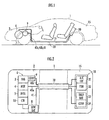
- Figure 1 is a configuration diagram of a vehicle wiring structure of the present invention applied to a hybrid vehicle
- figure 2 is a configuration diagram of main parts of the hybrid vehicle shown in figure 1 .
- a power unit 6 comprising an engine 3, a motor generator 4 (which corresponds to the electrical load of the present invention), an automatic transmission 5, an electric compressor 9 for an air-conditioning unit 9 (which corresponds to the electrical load of the present invention), a low voltage battery 8, and a controller 10 for controlling the operation and the like of the engine 3, is disposed in an engine room 2 at the vehicle front portion of the hybrid vehicle 1.
- the motor generator 4 is a three-phase DC brushless motor, and the driving force of the motor generator 4 and the engine 3 is transmitted to a front wheel 7, which is the drive wheel, via the automatic transmission 5. Furthermore, when the speed of the hybrid vehicle 1 is reduced and the like, the driving force is transmitted from the front wheel 7 to the motor generator 4, and the motor generator 4 functions as the power generator. Then, the generated electric power of the motor generator 4 is collected at a high voltage battery 33 via a motor inverter 32.
- the electric compressor 9 is provided with a compressor motor (not illustrated), and the driving shaft of the compressor motor is linkable with the crankshaft of the engine 3.
- the compressor motor is a three-phase motor, and electric power is provided to the compressor motor from a compressor inverter 31.
- An electric unit 30 (which corresponds to the power source of the present invention) is disposed in a trunk room 15 at the rear portion of the hybrid vehicle 1.
- the motor inverter 32 converts the direct current electricity provided form the high voltage battery 33 to a three-phase alternating current electricity and drives the motor generator 4. Furthermore, the compressor inverter 31 also converts the direct current electricity provided form the high voltage battery 33 to a three-phase alternating current electricity and drives the compressor 9.
- the motor generator 4 and the motor inverter 32 are connected by a three-phase power cable 40a for the motor.
- the compressor 9 and the compressor inverter 31 are connected by a three-phase power cable 40b for the compressor.
- the DC/DC converter 34 and the low voltage battery 8 are connected by a low voltage power cable 41 for providing electric power used for the operation of the controller or the like and for charging the low voltage battery 8.
- a metal pipe 20 with its one end inserted in the engine room 2 and the other end inserted in the trunk room 15. And the power cable 40a for the motor, the power cable 40b for the compressor, and the low voltage power cable 41 are inserted through the metal pipe 20, thereby connecting between the power unit 6 of the engine room 2 and the electric unit 30 of the trunk room 15.
- Figure 3(a) shows the configuration of the undersurface of the floor 19 of the hybrid vehicle 1, wherein one of the end part 22a of the metal pipe 20 is inserted to reach the vicinity of the power unit 6 disposed in the engine room 2, and the other end part 22b is inserted to reach the vicinity of the electric unit 30 disposed in the trunk room 15.
- an exhaust pipe 50 of the engine 3 is disposed at the floor undersurface 19, and the bottommost part 21 of the exhaust pipe 21 in the vertical direction is arranged at a position adjacent to an exhaust gas purification CAT 51 (catalyzer, catalyst) provided at a point along the exhaust pipe 50.
- CAT 51 catalyzer, catalyst
- a muffler 52 is provided at a rear position of the exhaust pipe 50.
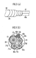
- Figure 3(b) is a cross-section diagram of the metal pipe 20, and as described above, the metal pipe 20 is inserted with the power cable 40a for the motor, the power cable 40b for the compressor, and the low voltage power cable 41.
- the metal pipe 20 is provided slanting from the two ends to the bottommost part 21 (a part where the height H from the ground surface G is lowest) in the vertical direction. Therefore, the dew condensation formed within the metal pipe 20 flows towards the bottommost part 21. And since the CAT 51 is disposed adjacent to the bottommost part 21 of the metal pipe 20, the dew condensation flown to the bottommost part 21 is heated by the heat radiation from the CAT 51 and evaporated.
- the CAT 51 corresponds to the heating unit of the present invention.
- figure 4(b) is a longitudinal sectional view of the place where the CAT 51 is disposed, and the bottommost part 21 of the metal pipe 20 is housed together with the exhaust pipe 50 and the CAT 51 within the concaved groove 61 formed to dispose the exhaust pipe 50 and the CAT 51 at the floor undersurface 60.
- the bottommost part 21 of the metal pipe 20 and the CAT 51 are arranged adjacently.
- the end part of the metal pipe 20 may be covered with a covering member such as a tape 70 or a corrugated tube or the like, in order to retain a plurality of power cables.
- a covering member such as a tape 70 or a corrugated tube or the like
- the evaporated moisture is released from spaces 7 1 a, 7 1 b, 71 c, 71 d, and 7 1 e between the power cables.
- the CAT 51 provided at the exhaust pipe 50 of the engine 3 is used as the heating unit of the present invention
- a muffler 52 provided at the exhaust pipe 50 may be used, or an electric heater for heating the bottommost part of the electric pipe 20 may be provided.
- the metal pipe in which the power cable is inserted is prevented from rusting by dew condensation, and therefore it is useful for vehicle wiring.
Landscapes
- Engineering & Computer Science (AREA)
- Mechanical Engineering (AREA)
- Chemical & Material Sciences (AREA)
- Combustion & Propulsion (AREA)
- Transportation (AREA)
- Electric Propulsion And Braking For Vehicles (AREA)
- Details Of Indoor Wiring (AREA)
- Air-Conditioning For Vehicles (AREA)
- Arrangement Or Mounting Of Propulsion Units For Vehicles (AREA)
Abstract

Description
- The present invention relates to a wiring structure for a vehicle to connect between a power source and an electrical load equipped in a vehicle by a power cable.
- Conventionally, for example, in a hybrid vehicle having an engine and a motor as a driving source, there is known a vehicle wiring structure for connecting between the motor disposed in the engine room in the front portion of the vehicle and the battery or PDU (Power Drive Unit) provided in the vicinity of the trunk room in the rear portion of the vehicle, by a power cable which is inserted through a metal pipe disposed in the under surface of the floor of the vehicle (for example, refer to Japanese Patent Laid-Open Publication No.
2005-218189 - As described above, in case of wiring by using a metal pipe, there are cases where the metal pipe is rusted (be electrically corrosive) due to dew condensation formed inside the metal pipe. In order to prevent this, it is necessary to take countermeasures to provide surface treatment to the inner surface of the metal pipe such as coating or the like, or to use a metal pipe using materials having high durability against rust, or the like.
- In this regard, it is the object of the present invention to provide a vehicle wiring structure which prevents the metal pipe from rusting due to dew condensation formed inside the metal pipe in which the power cable is inserted through, in a suppressed cost.
- The present invention was made to fulfill the above object and relates to a vehicle wiring structure which uses a power cable to connect between a power source and an electrical load disposed, inside a vehicle, with a space therebetween in a vehicle front-to-back direction, comprising a metal pipe disposed on vehicle floor under surface between a position below where the power source is installed and a position below where the electrical load is installed, and two ends thereof are inserted into the vehicle, and a power cable inserted through an inside of the metal pipe and which connects the power source and the electrical load.
- Moreover, the present invention is characterized in that the metal pipe is provided slanting from the two ends toward a bottommost part, in the vertical direction, and comprising a heating unit to heat the bottommost part.
- According to the present invention, the dew condensation formed inside the metal pipe flows towards the bottommost part in the vertical direction of the metal pipe. Since the bottommost part is being heated by the heating unit, the dew condensation reaching the vicinity of the bottommost part is heated and evaporated. Therefore, it is able to prevent the metal pipe from rusting due to dew condensation. Further, in such case, there is no need to take countermeasures of coating in order to prevent the metal pipe from rusting or using materials with high durability against rust, or the like, thereby being able to suppress the cost of the metal pipe.
- Moreover, the present invention is characterized in that the heating unit is an exhaust pipe of an engine installed in the vehicle, and a part including the bottommost part of the metal pipe and the exhaust pipe is proximately disposed within a recessed portion formed in the vehicle floor undersurface.
- According to the present invention, it is able to evaporate dew condensation reaching the vicinity of the bottommost part of the metal pipe by effectively using the heat radiation from the exhaust pipe without additionally providing a heating unit.
- Moreover, the present invention is characterized in that the heating unit is an electric heater provided at the bottommost part of the metal pipe.
- According to the present invention, it is able to evaporate dew condensation reaching the vicinity of the bottommost part of the metal pipe by effectively heating the bottommost part of the metal pipe by the electric heater provided at the bottommost part.
- Moreover, the present invention is characterized in that at least one end of the metal pipe is released to air.
- According to the present invention, the evaporated moisture heated by the heating unit can be discharged from the end part of the metal pulp by having at least one end of the metal pipe being released to air. Therefore, it is able to prevent the evaporated moisture from condensing again.
- Moreover, the present invention is characterized in that a plurality of power cables are provided inside the metal pipe, and at least one end of the metal pipe is released to air through a space between the plurality of power cables, and then is covered by a covering member.
- According to the present invention, it is able to release to air at least one end of the metal pipe through the space between the plurality of power cables, and then retain the plurality of power cables at the end part of the metal pipe.
-
- [
Fig. 1 ] A configuration diagram of a vehicle wiring structure of the present invention applied to a hybrid vehicle. - [
Fig. 2 ] A configuration diagram of main parts of the hybrid vehicle shown infigure 1 . - [
Fig. 3 ] A configuration diagram of floor undersurface of the hybrid vehicle, and a cross-section diagram of the metal pipe inserted with the power cables. - [
Fig. 4 ] An explanatory diagram of an embodiment showing the alignment of the metal pipe and the CAT. - [
Fig. 5 ] An explanatory diagram of the treatment at the end part of the metal pipe. - An embodiment of the present invention will be explained referring to
figures 1 to 5 .Figure 1 is a configuration diagram of a vehicle wiring structure of the present invention applied to a hybrid vehicle, andfigure 2 is a configuration diagram of main parts of the hybrid vehicle shown infigure 1 . - Referring to
figures 1 and 2 , apower unit 6 comprising anengine 3, a motor generator 4 (which corresponds to the electrical load of the present invention), anautomatic transmission 5, anelectric compressor 9 for an air-conditioning unit 9 (which corresponds to the electrical load of the present invention), alow voltage battery 8, and acontroller 10 for controlling the operation and the like of theengine 3, is disposed in an engine room 2 at the vehicle front portion of the hybrid vehicle 1. - The
motor generator 4 is a three-phase DC brushless motor, and the driving force of themotor generator 4 and theengine 3 is transmitted to a front wheel 7, which is the drive wheel, via theautomatic transmission 5. Furthermore, when the speed of the hybrid vehicle 1 is reduced and the like, the driving force is transmitted from the front wheel 7 to themotor generator 4, and themotor generator 4 functions as the power generator. Then, the generated electric power of themotor generator 4 is collected at ahigh voltage battery 33 via amotor inverter 32. - The
electric compressor 9 is provided with a compressor motor (not illustrated), and the driving shaft of the compressor motor is linkable with the crankshaft of theengine 3. The compressor motor is a three-phase motor, and electric power is provided to the compressor motor from acompressor inverter 31. - An electric unit 30 (which corresponds to the power source of the present invention) is disposed in a
trunk room 15 at the rear portion of the hybrid vehicle 1. The motor inverter 32 for a rotational control of themotor generator 4, thecompressor inverter 31 for a rotational control of theelectric compressor 9, thehigh voltage battery 33, and a DC/DC converter 34 for depressing the output voltage of thehigh voltage battery 33, is housed in theelectric unit 30. - The
motor inverter 32 converts the direct current electricity provided form thehigh voltage battery 33 to a three-phase alternating current electricity and drives themotor generator 4. Furthermore, thecompressor inverter 31 also converts the direct current electricity provided form thehigh voltage battery 33 to a three-phase alternating current electricity and drives thecompressor 9. - The
motor generator 4 and themotor inverter 32 are connected by a three-phase power cable 40a for the motor. Similarly, thecompressor 9 and thecompressor inverter 31 are connected by a three-phase power cable 40b for the compressor. Furthermore, the DC/DC converter 34 and thelow voltage battery 8 are connected by a lowvoltage power cable 41 for providing electric power used for the operation of the controller or the like and for charging thelow voltage battery 8. - At the undersurface of a
floor 19 of the hybrid vehicle 1, there is disposed ametal pipe 20 with its one end inserted in the engine room 2 and the other end inserted in thetrunk room 15. And thepower cable 40a for the motor, thepower cable 40b for the compressor, and the lowvoltage power cable 41 are inserted through themetal pipe 20, thereby connecting between thepower unit 6 of the engine room 2 and theelectric unit 30 of thetrunk room 15. -
Figure 3(a) shows the configuration of the undersurface of thefloor 19 of the hybrid vehicle 1, wherein one of the end part 22a of themetal pipe 20 is inserted to reach the vicinity of thepower unit 6 disposed in the engine room 2, and the other end part 22b is inserted to reach the vicinity of theelectric unit 30 disposed in thetrunk room 15. - Furthermore, an
exhaust pipe 50 of theengine 3 is disposed at thefloor undersurface 19, and thebottommost part 21 of theexhaust pipe 21 in the vertical direction is arranged at a position adjacent to an exhaust gas purification CAT 51 (catalyzer, catalyst) provided at a point along theexhaust pipe 50. In addition, amuffler 52 is provided at a rear position of theexhaust pipe 50. -
Figure 3(b) is a cross-section diagram of themetal pipe 20, and as described above, themetal pipe 20 is inserted with thepower cable 40a for the motor, thepower cable 40b for the compressor, and the lowvoltage power cable 41. - Next, referring to
figure 4(a) , themetal pipe 20 is provided slanting from the two ends to the bottommost part 21 (a part where the height H from the ground surface G is lowest) in the vertical direction. Therefore, the dew condensation formed within themetal pipe 20 flows towards thebottommost part 21. And since theCAT 51 is disposed adjacent to thebottommost part 21 of themetal pipe 20, the dew condensation flown to thebottommost part 21 is heated by the heat radiation from theCAT 51 and evaporated. - Therefore, it is able to prevent the
metal pipe 20 form rusting by the dew condensation formed in themetal pipe 20 being remained in themetal pipe 20. In this case, theCAT 51 corresponds to the heating unit of the present invention. - And then, since the moisture evaporated at the
bottommost part 21 is discharged from both ends of themetal pipe 20 which is released to air, it is able to prevent the evaporated moisture from condensing again in themetal pipe 20. Furthermore,figure 4(b) is a longitudinal sectional view of the place where theCAT 51 is disposed, and thebottommost part 21 of themetal pipe 20 is housed together with theexhaust pipe 50 and theCAT 51 within theconcaved groove 61 formed to dispose theexhaust pipe 50 and theCAT 51 at thefloor undersurface 60. By this, thebottommost part 21 of themetal pipe 20 and theCAT 51 are arranged adjacently. - As shown in
figure 5(a) , the end part of themetal pipe 20 may be covered with a covering member such as atape 70 or a corrugated tube or the like, in order to retain a plurality of power cables. In such case, as shown infigure 5(b) , the evaporated moisture is released from spaces 7 1 a, 7 1 b, 71 c, 71 d, and 7 1 e between the power cables. - Furthermore, in the present embodiment, although the
CAT 51 provided at theexhaust pipe 50 of theengine 3 is used as the heating unit of the present invention, alternatively amuffler 52 provided at theexhaust pipe 50 may be used, or an electric heater for heating the bottommost part of theelectric pipe 20 may be provided. Industrial Application - As described above, according to the vehicle wiring structure of the present invention, the metal pipe in which the power cable is inserted, is prevented from rusting by dew condensation, and therefore it is useful for vehicle wiring.
Claims (5)
- A vehicle wiring structure which uses a power cable to connect between a power source and an electrical load disposed, inside a vehicle, with a space therebetween in a vehicle front-to-back direction, comprising;
a metal pipe disposed on a vehicle floor undersurface between a position below where the power source is installed and a position below where the electrical load is installed, and two ends thereof are inserted into the vehicle; and
a power cable inserted through an inside of the metal pipe and which connects the power source and the electrical load;
wherein the metal pipe is provided slanting from the two ends toward a bottommost part in a vertical direction, and
wherein a heating unit is provided to heat the bottommost part. - The vehicle wiring structure according to claim 1, wherein the heating unit is an exhaust pipe of an engine installed in the vehicle, and
wherein a part including the bottommost part of the metal pipe and the exhaust pipe are proximately disposed within a recessed portion formed on the vehicle floor undersurface. - The vehicle wiring structure according to claim 1, wherein the heating unit is an electric heater provided at the bottommost part of the metal pipe.
- The vehicle wiring structure according to claim 1, wherein at least one end of the metal pipe is released to air.
- The vehicle wiring structure according to claim 1, wherein a plurality of power cables are provided inside the metal pipe, and
wherein at least one end of the metal pipe is released to air through a space between the plurality of power cables, and then is covered by a covering member.
Applications Claiming Priority (2)
| Application Number | Priority Date | Filing Date | Title |
|---|---|---|---|
| JP2008322891A JP5047143B2 (en) | 2008-12-18 | 2008-12-18 | Vehicle wiring structure |
| PCT/JP2009/006600 WO2010070833A1 (en) | 2008-12-18 | 2009-12-03 | Vehicle wiring structure |
Publications (3)
| Publication Number | Publication Date |
|---|---|
| EP2368769A1 true EP2368769A1 (en) | 2011-09-28 |
| EP2368769A4 EP2368769A4 (en) | 2012-05-09 |
| EP2368769B1 EP2368769B1 (en) | 2013-11-13 |
Family
ID=42268516
Family Applications (1)
| Application Number | Title | Priority Date | Filing Date |
|---|---|---|---|
| EP09833143.2A Not-in-force EP2368769B1 (en) | 2008-12-18 | 2009-12-03 | Vehicle wiring structure |
Country Status (6)
| Country | Link |
|---|---|
| US (1) | US8481856B2 (en) |
| EP (1) | EP2368769B1 (en) |
| JP (1) | JP5047143B2 (en) |
| CN (1) | CN102245438B (en) |
| BR (1) | BRPI0923163A8 (en) |
| WO (1) | WO2010070833A1 (en) |
Families Citing this family (8)
| Publication number | Priority date | Publication date | Assignee | Title |
|---|---|---|---|---|
| JP5645075B2 (en) | 2011-02-28 | 2014-12-24 | 株式会社オートネットワーク技術研究所 | Shield conductor |
| JP5691642B2 (en) * | 2011-02-28 | 2015-04-01 | 株式会社オートネットワーク技術研究所 | Shield conductor |
| JP5970870B2 (en) | 2012-03-06 | 2016-08-17 | スズキ株式会社 | Electric parts mounting structure for hybrid vehicle |
| EP2899073A4 (en) * | 2012-09-18 | 2015-11-04 | Nissan Motor | Harness routing structure for electric vehicle |
| JP6357512B2 (en) * | 2016-09-13 | 2018-07-11 | 本田技研工業株式会社 | Harness holder, power equipment unit and vehicle |
| JP7107669B2 (en) * | 2017-12-04 | 2022-07-27 | 矢崎総業株式会社 | In-vehicle control system and wire harness |
| JP6673399B2 (en) * | 2018-05-25 | 2020-03-25 | 株式会社オートネットワーク技術研究所 | Wiring member fixing structure |
| JP7409124B2 (en) * | 2020-02-04 | 2024-01-09 | 住友電装株式会社 | wire harness |
Family Cites Families (10)
| Publication number | Priority date | Publication date | Assignee | Title |
|---|---|---|---|---|
| US4214147A (en) * | 1978-06-19 | 1980-07-22 | Kraver Richard A | Electric heating system for controlling temperature of pipes to prevent freezing and condensation |
| JPH09267734A (en) * | 1996-04-03 | 1997-10-14 | Nissan Motor Co Ltd | Anti-lock brake device |
| JP3909763B2 (en) * | 2002-11-20 | 2007-04-25 | 株式会社オートネットワーク技術研究所 | Vehicle conductive path with shield function |
| JP4015120B2 (en) | 2004-01-28 | 2007-11-28 | 本田技研工業株式会社 | Power cable holding structure for vehicle and method for assembling power cable assembly for vehicle |
| JP2005306104A (en) * | 2004-04-19 | 2005-11-04 | Nissan Motor Co Ltd | Fuel cell automobile |
| JP2006303376A (en) * | 2005-04-25 | 2006-11-02 | Auto Network Gijutsu Kenkyusho:Kk | Shield conductive path |
| JP2007008423A (en) * | 2005-07-04 | 2007-01-18 | Auto Network Gijutsu Kenkyusho:Kk | Shield conductor |
| WO2007004674A1 (en) * | 2005-07-05 | 2007-01-11 | Autonetworks Technologies, Ltd. | Shielded electrically conductive body |
| JPWO2007032391A1 (en) | 2005-09-13 | 2009-03-19 | 株式会社オートネットワーク技術研究所 | Conductor for vehicle |
| JP4238899B2 (en) * | 2006-08-30 | 2009-03-18 | トヨタ自動車株式会社 | Exhaust heat exchanger mounting structure |
-
2008
- 2008-12-18 JP JP2008322891A patent/JP5047143B2/en not_active Expired - Fee Related
-
2009
- 2009-12-03 BR BRPI0923163A patent/BRPI0923163A8/en active Search and Examination
- 2009-12-03 CN CN2009801505617A patent/CN102245438B/en not_active Expired - Fee Related
- 2009-12-03 WO PCT/JP2009/006600 patent/WO2010070833A1/en not_active Ceased
- 2009-12-03 US US13/131,012 patent/US8481856B2/en not_active Expired - Fee Related
- 2009-12-03 EP EP09833143.2A patent/EP2368769B1/en not_active Not-in-force
Also Published As
| Publication number | Publication date |
|---|---|
| BRPI0923163A2 (en) | 2016-02-10 |
| CN102245438A (en) | 2011-11-16 |
| JP2010143408A (en) | 2010-07-01 |
| CN102245438B (en) | 2013-12-04 |
| JP5047143B2 (en) | 2012-10-10 |
| US20110232958A1 (en) | 2011-09-29 |
| EP2368769B1 (en) | 2013-11-13 |
| US8481856B2 (en) | 2013-07-09 |
| WO2010070833A1 (en) | 2010-06-24 |
| EP2368769A4 (en) | 2012-05-09 |
| BRPI0923163A8 (en) | 2017-09-12 |
Similar Documents
| Publication | Publication Date | Title |
|---|---|---|
| EP2368769B1 (en) | Vehicle wiring structure | |
| EP2380780B1 (en) | Vehicle wiring structure | |
| US7497284B2 (en) | Power cable holding structure for vehicle and method of assembling power cable assembly for vehicle | |
| EP1440834B1 (en) | Vehicle power cables retaining structure | |
| CN204451974U (en) | The integrated driving assembly of battery-driven car | |
| JP4935567B2 (en) | housing | |
| JP4285405B2 (en) | Hybrid car | |
| CN108667178B (en) | Rotor end plate for an electric machine | |
| EP2613398A1 (en) | Shovel | |
| EP2772394A1 (en) | Wiring protective cover structure for electric vehicle | |
| US8110938B2 (en) | Line connection structure for electric equipment and electric vehicle | |
| WO2017110138A1 (en) | Mounting structure for high-voltage control device unit | |
| EP1068976A3 (en) | Shift position indicating device for hybrid vehicle | |
| CN103847499B (en) | Cable wiring structure | |
| JP4835192B2 (en) | Vehicle drive device | |
| WO2007105465A1 (en) | Structure for mounting electrical machinery and electric vehicle | |
| CN111293269A (en) | Electric vehicle bus bars secured using deformed regions of attachment structures | |
| US9131629B2 (en) | Cooling apparatus for a motor vehicle having a drive which comprises two motors | |
| JP3876798B2 (en) | Power converter for vehicle | |
| US20070203629A1 (en) | Vehicle Axle System, Torque Tube, Vehicle Axle, And Vehicle | |
| JP6720843B2 (en) | Battery heater system | |
| US11865982B2 (en) | Vehicle wiring harness housing | |
| CA3116990A1 (en) | Design of powertrain system assembly for ev |
Legal Events
| Date | Code | Title | Description |
|---|---|---|---|
| PUAI | Public reference made under article 153(3) epc to a published international application that has entered the european phase |
Free format text: ORIGINAL CODE: 0009012 |
|
| 17P | Request for examination filed |
Effective date: 20110616 |
|
| AK | Designated contracting states |
Kind code of ref document: A1 Designated state(s): AT BE BG CH CY CZ DE DK EE ES FI FR GB GR HR HU IE IS IT LI LT LU LV MC MK MT NL NO PL PT RO SE SI SK SM TR |
|
| DAX | Request for extension of the european patent (deleted) | ||
| A4 | Supplementary search report drawn up and despatched |
Effective date: 20120405 |
|
| RIC1 | Information provided on ipc code assigned before grant |
Ipc: B60L 11/14 20060101ALI20120330BHEP Ipc: B60R 16/02 20060101AFI20120330BHEP |
|
| 17Q | First examination report despatched |
Effective date: 20120608 |
|
| GRAP | Despatch of communication of intention to grant a patent |
Free format text: ORIGINAL CODE: EPIDOSNIGR1 |
|
| INTG | Intention to grant announced |
Effective date: 20130614 |
|
| GRAS | Grant fee paid |
Free format text: ORIGINAL CODE: EPIDOSNIGR3 |
|
| GRAA | (expected) grant |
Free format text: ORIGINAL CODE: 0009210 |
|
| AK | Designated contracting states |
Kind code of ref document: B1 Designated state(s): AT BE BG CH CY CZ DE DK EE ES FI FR GB GR HR HU IE IS IT LI LT LU LV MC MK MT NL NO PL PT RO SE SI SK SM TR |
|
| REG | Reference to a national code |
Ref country code: GB Ref legal event code: FG4D |
|
| REG | Reference to a national code |
Ref country code: CH Ref legal event code: EP |
|
| REG | Reference to a national code |
Ref country code: AT Ref legal event code: REF Ref document number: 640428 Country of ref document: AT Kind code of ref document: T Effective date: 20131215 |
|
| REG | Reference to a national code |
Ref country code: IE Ref legal event code: FG4D |
|
| REG | Reference to a national code |
Ref country code: DE Ref legal event code: R096 Ref document number: 602009020133 Country of ref document: DE Effective date: 20140109 |
|
| REG | Reference to a national code |
Ref country code: NL Ref legal event code: T3 |
|
| REG | Reference to a national code |
Ref country code: AT Ref legal event code: MK05 Ref document number: 640428 Country of ref document: AT Kind code of ref document: T Effective date: 20131113 |
|
| REG | Reference to a national code |
Ref country code: LT Ref legal event code: MG4D |
|
| PG25 | Lapsed in a contracting state [announced via postgrant information from national office to epo] |
Ref country code: LT Free format text: LAPSE BECAUSE OF FAILURE TO SUBMIT A TRANSLATION OF THE DESCRIPTION OR TO PAY THE FEE WITHIN THE PRESCRIBED TIME-LIMIT Effective date: 20131113 Ref country code: HR Free format text: LAPSE BECAUSE OF FAILURE TO SUBMIT A TRANSLATION OF THE DESCRIPTION OR TO PAY THE FEE WITHIN THE PRESCRIBED TIME-LIMIT Effective date: 20131113 Ref country code: FI Free format text: LAPSE BECAUSE OF FAILURE TO SUBMIT A TRANSLATION OF THE DESCRIPTION OR TO PAY THE FEE WITHIN THE PRESCRIBED TIME-LIMIT Effective date: 20131113 Ref country code: NO Free format text: LAPSE BECAUSE OF FAILURE TO SUBMIT A TRANSLATION OF THE DESCRIPTION OR TO PAY THE FEE WITHIN THE PRESCRIBED TIME-LIMIT Effective date: 20140213 Ref country code: SE Free format text: LAPSE BECAUSE OF FAILURE TO SUBMIT A TRANSLATION OF THE DESCRIPTION OR TO PAY THE FEE WITHIN THE PRESCRIBED TIME-LIMIT Effective date: 20131113 Ref country code: IS Free format text: LAPSE BECAUSE OF FAILURE TO SUBMIT A TRANSLATION OF THE DESCRIPTION OR TO PAY THE FEE WITHIN THE PRESCRIBED TIME-LIMIT Effective date: 20140313 |
|
| PG25 | Lapsed in a contracting state [announced via postgrant information from national office to epo] |
Ref country code: ES Free format text: LAPSE BECAUSE OF FAILURE TO SUBMIT A TRANSLATION OF THE DESCRIPTION OR TO PAY THE FEE WITHIN THE PRESCRIBED TIME-LIMIT Effective date: 20131113 Ref country code: AT Free format text: LAPSE BECAUSE OF FAILURE TO SUBMIT A TRANSLATION OF THE DESCRIPTION OR TO PAY THE FEE WITHIN THE PRESCRIBED TIME-LIMIT Effective date: 20131113 Ref country code: CY Free format text: LAPSE BECAUSE OF FAILURE TO SUBMIT A TRANSLATION OF THE DESCRIPTION OR TO PAY THE FEE WITHIN THE PRESCRIBED TIME-LIMIT Effective date: 20131113 Ref country code: LV Free format text: LAPSE BECAUSE OF FAILURE TO SUBMIT A TRANSLATION OF THE DESCRIPTION OR TO PAY THE FEE WITHIN THE PRESCRIBED TIME-LIMIT Effective date: 20131113 Ref country code: BE Free format text: LAPSE BECAUSE OF FAILURE TO SUBMIT A TRANSLATION OF THE DESCRIPTION OR TO PAY THE FEE WITHIN THE PRESCRIBED TIME-LIMIT Effective date: 20131113 |
|
| PG25 | Lapsed in a contracting state [announced via postgrant information from national office to epo] |
Ref country code: PT Free format text: LAPSE BECAUSE OF FAILURE TO SUBMIT A TRANSLATION OF THE DESCRIPTION OR TO PAY THE FEE WITHIN THE PRESCRIBED TIME-LIMIT Effective date: 20140313 |
|
| PG25 | Lapsed in a contracting state [announced via postgrant information from national office to epo] |
Ref country code: EE Free format text: LAPSE BECAUSE OF FAILURE TO SUBMIT A TRANSLATION OF THE DESCRIPTION OR TO PAY THE FEE WITHIN THE PRESCRIBED TIME-LIMIT Effective date: 20131113 |
|
| REG | Reference to a national code |
Ref country code: CH Ref legal event code: PL |
|
| REG | Reference to a national code |
Ref country code: DE Ref legal event code: R097 Ref document number: 602009020133 Country of ref document: DE |
|
| REG | Reference to a national code |
Ref country code: DE Ref legal event code: R084 Ref document number: 602009020133 Country of ref document: DE |
|
| PG25 | Lapsed in a contracting state [announced via postgrant information from national office to epo] |
Ref country code: CZ Free format text: LAPSE BECAUSE OF FAILURE TO SUBMIT A TRANSLATION OF THE DESCRIPTION OR TO PAY THE FEE WITHIN THE PRESCRIBED TIME-LIMIT Effective date: 20131113 Ref country code: SK Free format text: LAPSE BECAUSE OF FAILURE TO SUBMIT A TRANSLATION OF THE DESCRIPTION OR TO PAY THE FEE WITHIN THE PRESCRIBED TIME-LIMIT Effective date: 20131113 Ref country code: RO Free format text: LAPSE BECAUSE OF FAILURE TO SUBMIT A TRANSLATION OF THE DESCRIPTION OR TO PAY THE FEE WITHIN THE PRESCRIBED TIME-LIMIT Effective date: 20131113 Ref country code: PL Free format text: LAPSE BECAUSE OF FAILURE TO SUBMIT A TRANSLATION OF THE DESCRIPTION OR TO PAY THE FEE WITHIN THE PRESCRIBED TIME-LIMIT Effective date: 20131113 |
|
| REG | Reference to a national code |
Ref country code: GB Ref legal event code: 746 Effective date: 20140813 |
|
| PLBE | No opposition filed within time limit |
Free format text: ORIGINAL CODE: 0009261 |
|
| STAA | Information on the status of an ep patent application or granted ep patent |
Free format text: STATUS: NO OPPOSITION FILED WITHIN TIME LIMIT |
|
| REG | Reference to a national code |
Ref country code: IE Ref legal event code: MM4A |
|
| PG25 | Lapsed in a contracting state [announced via postgrant information from national office to epo] |
Ref country code: DK Free format text: LAPSE BECAUSE OF FAILURE TO SUBMIT A TRANSLATION OF THE DESCRIPTION OR TO PAY THE FEE WITHIN THE PRESCRIBED TIME-LIMIT Effective date: 20131113 |
|
| REG | Reference to a national code |
Ref country code: DE Ref legal event code: R084 Ref document number: 602009020133 Country of ref document: DE Effective date: 20140821 |
|
| 26N | No opposition filed |
Effective date: 20140814 |
|
| PG25 | Lapsed in a contracting state [announced via postgrant information from national office to epo] |
Ref country code: LI Free format text: LAPSE BECAUSE OF NON-PAYMENT OF DUE FEES Effective date: 20131231 Ref country code: CH Free format text: LAPSE BECAUSE OF NON-PAYMENT OF DUE FEES Effective date: 20131231 Ref country code: IE Free format text: LAPSE BECAUSE OF NON-PAYMENT OF DUE FEES Effective date: 20131203 |
|
| REG | Reference to a national code |
Ref country code: DE Ref legal event code: R097 Ref document number: 602009020133 Country of ref document: DE Effective date: 20140814 |
|
| PG25 | Lapsed in a contracting state [announced via postgrant information from national office to epo] |
Ref country code: SI Free format text: LAPSE BECAUSE OF FAILURE TO SUBMIT A TRANSLATION OF THE DESCRIPTION OR TO PAY THE FEE WITHIN THE PRESCRIBED TIME-LIMIT Effective date: 20131113 |
|
| PG25 | Lapsed in a contracting state [announced via postgrant information from national office to epo] |
Ref country code: MC Free format text: LAPSE BECAUSE OF FAILURE TO SUBMIT A TRANSLATION OF THE DESCRIPTION OR TO PAY THE FEE WITHIN THE PRESCRIBED TIME-LIMIT Effective date: 20131113 |
|
| PG25 | Lapsed in a contracting state [announced via postgrant information from national office to epo] |
Ref country code: SM Free format text: LAPSE BECAUSE OF FAILURE TO SUBMIT A TRANSLATION OF THE DESCRIPTION OR TO PAY THE FEE WITHIN THE PRESCRIBED TIME-LIMIT Effective date: 20131113 |
|
| PG25 | Lapsed in a contracting state [announced via postgrant information from national office to epo] |
Ref country code: TR Free format text: LAPSE BECAUSE OF FAILURE TO SUBMIT A TRANSLATION OF THE DESCRIPTION OR TO PAY THE FEE WITHIN THE PRESCRIBED TIME-LIMIT Effective date: 20131113 |
|
| PG25 | Lapsed in a contracting state [announced via postgrant information from national office to epo] |
Ref country code: BG Free format text: LAPSE BECAUSE OF FAILURE TO SUBMIT A TRANSLATION OF THE DESCRIPTION OR TO PAY THE FEE WITHIN THE PRESCRIBED TIME-LIMIT Effective date: 20131113 Ref country code: LU Free format text: LAPSE BECAUSE OF NON-PAYMENT OF DUE FEES Effective date: 20131203 Ref country code: MK Free format text: LAPSE BECAUSE OF FAILURE TO SUBMIT A TRANSLATION OF THE DESCRIPTION OR TO PAY THE FEE WITHIN THE PRESCRIBED TIME-LIMIT Effective date: 20131113 Ref country code: HU Free format text: LAPSE BECAUSE OF FAILURE TO SUBMIT A TRANSLATION OF THE DESCRIPTION OR TO PAY THE FEE WITHIN THE PRESCRIBED TIME-LIMIT; INVALID AB INITIO Effective date: 20091203 |
|
| PG25 | Lapsed in a contracting state [announced via postgrant information from national office to epo] |
Ref country code: IT Free format text: LAPSE BECAUSE OF FAILURE TO SUBMIT A TRANSLATION OF THE DESCRIPTION OR TO PAY THE FEE WITHIN THE PRESCRIBED TIME-LIMIT Effective date: 20131113 Ref country code: GR Free format text: LAPSE BECAUSE OF NON-PAYMENT OF DUE FEES Effective date: 20131113 Ref country code: MT Free format text: LAPSE BECAUSE OF FAILURE TO SUBMIT A TRANSLATION OF THE DESCRIPTION OR TO PAY THE FEE WITHIN THE PRESCRIBED TIME-LIMIT Effective date: 20131113 |
|
| REG | Reference to a national code |
Ref country code: FR Ref legal event code: PLFP Year of fee payment: 7 |
|
| PGFP | Annual fee paid to national office [announced via postgrant information from national office to epo] |
Ref country code: DE Payment date: 20151125 Year of fee payment: 7 Ref country code: GB Payment date: 20151202 Year of fee payment: 7 |
|
| PGFP | Annual fee paid to national office [announced via postgrant information from national office to epo] |
Ref country code: NL Payment date: 20151210 Year of fee payment: 7 Ref country code: FR Payment date: 20151110 Year of fee payment: 7 |
|
| PG25 | Lapsed in a contracting state [announced via postgrant information from national office to epo] |
Ref country code: GR Free format text: LAPSE BECAUSE OF FAILURE TO SUBMIT A TRANSLATION OF THE DESCRIPTION OR TO PAY THE FEE WITHIN THE PRESCRIBED TIME-LIMIT Effective date: 20140214 |
|
| REG | Reference to a national code |
Ref country code: DE Ref legal event code: R119 Ref document number: 602009020133 Country of ref document: DE |
|
| REG | Reference to a national code |
Ref country code: NL Ref legal event code: MM Effective date: 20170101 |
|
| GBPC | Gb: european patent ceased through non-payment of renewal fee |
Effective date: 20161203 |
|
| PG25 | Lapsed in a contracting state [announced via postgrant information from national office to epo] |
Ref country code: NL Free format text: LAPSE BECAUSE OF NON-PAYMENT OF DUE FEES Effective date: 20170101 |
|
| REG | Reference to a national code |
Ref country code: FR Ref legal event code: ST Effective date: 20170831 |
|
| PG25 | Lapsed in a contracting state [announced via postgrant information from national office to epo] |
Ref country code: FR Free format text: LAPSE BECAUSE OF NON-PAYMENT OF DUE FEES Effective date: 20170102 |
|
| PG25 | Lapsed in a contracting state [announced via postgrant information from national office to epo] |
Ref country code: GB Free format text: LAPSE BECAUSE OF NON-PAYMENT OF DUE FEES Effective date: 20161203 Ref country code: DE Free format text: LAPSE BECAUSE OF NON-PAYMENT OF DUE FEES Effective date: 20170701 |