EP2368753A1 - Child safety seat with energy absorbing apparatus - Google Patents
Child safety seat with energy absorbing apparatus Download PDFInfo
- Publication number
- EP2368753A1 EP2368753A1 EP11001951A EP11001951A EP2368753A1 EP 2368753 A1 EP2368753 A1 EP 2368753A1 EP 11001951 A EP11001951 A EP 11001951A EP 11001951 A EP11001951 A EP 11001951A EP 2368753 A1 EP2368753 A1 EP 2368753A1
- Authority
- EP
- European Patent Office
- Prior art keywords
- seat
- safety
- cavity
- safety seat
- energy absorbing
- Prior art date
- Legal status (The legal status is an assumption and is not a legal conclusion. Google has not performed a legal analysis and makes no representation as to the accuracy of the status listed.)
- Granted
Links
- 238000000034 method Methods 0.000 claims description 6
- 239000003112 inhibitor Substances 0.000 claims description 5
- 230000000007 visual effect Effects 0.000 claims description 5
- 230000000694 effects Effects 0.000 claims description 4
- 238000009434 installation Methods 0.000 abstract description 14
- 208000014674 injury Diseases 0.000 description 13
- 208000027418 Wounds and injury Diseases 0.000 description 12
- 230000006378 damage Effects 0.000 description 12
- 230000005484 gravity Effects 0.000 description 12
- 230000008859 change Effects 0.000 description 10
- 239000000463 material Substances 0.000 description 10
- 239000011358 absorbing material Substances 0.000 description 8
- 230000037361 pathway Effects 0.000 description 6
- 238000010521 absorption reaction Methods 0.000 description 5
- 230000001133 acceleration Effects 0.000 description 5
- 230000008901 benefit Effects 0.000 description 4
- 239000002184 metal Substances 0.000 description 4
- 239000004033 plastic Substances 0.000 description 4
- 229920003023 plastic Polymers 0.000 description 4
- 230000002459 sustained effect Effects 0.000 description 3
- 230000002411 adverse Effects 0.000 description 2
- 230000007246 mechanism Effects 0.000 description 2
- 238000012986 modification Methods 0.000 description 2
- 230000004048 modification Effects 0.000 description 2
- -1 padding Substances 0.000 description 2
- 230000009467 reduction Effects 0.000 description 2
- 206010019196 Head injury Diseases 0.000 description 1
- 239000004743 Polypropylene Substances 0.000 description 1
- 239000006096 absorbing agent Substances 0.000 description 1
- 239000003086 colorant Substances 0.000 description 1
- 239000002131 composite material Substances 0.000 description 1
- 230000001010 compromised effect Effects 0.000 description 1
- 230000005489 elastic deformation Effects 0.000 description 1
- 229920001971 elastomer Polymers 0.000 description 1
- 239000004794 expanded polystyrene Substances 0.000 description 1
- 239000004744 fabric Substances 0.000 description 1
- 239000012530 fluid Substances 0.000 description 1
- 239000006260 foam Substances 0.000 description 1
- 229920001821 foam rubber Polymers 0.000 description 1
- 238000003780 insertion Methods 0.000 description 1
- 230000037431 insertion Effects 0.000 description 1
- 238000005259 measurement Methods 0.000 description 1
- 230000000116 mitigating effect Effects 0.000 description 1
- 239000000203 mixture Substances 0.000 description 1
- 229920001084 poly(chloroprene) Polymers 0.000 description 1
- 229920001155 polypropylene Polymers 0.000 description 1
- 239000005060 rubber Substances 0.000 description 1
- 230000035939 shock Effects 0.000 description 1
- 238000004904 shortening Methods 0.000 description 1
- 230000008733 trauma Effects 0.000 description 1
Images


Classifications
-
- B—PERFORMING OPERATIONS; TRANSPORTING
- B60—VEHICLES IN GENERAL
- B60N—SEATS SPECIALLY ADAPTED FOR VEHICLES; VEHICLE PASSENGER ACCOMMODATION NOT OTHERWISE PROVIDED FOR
- B60N2/00—Seats specially adapted for vehicles; Arrangement or mounting of seats in vehicles
- B60N2/24—Seats specially adapted for vehicles; Arrangement or mounting of seats in vehicles for particular purposes or particular vehicles
- B60N2/26—Seats specially adapted for vehicles; Arrangement or mounting of seats in vehicles for particular purposes or particular vehicles for children
- B60N2/28—Seats readily mountable on, and dismountable from, existing seats or other parts of the vehicle
- B60N2/2887—Fixation to a transversal anchorage bar, e.g. isofix
-
- B—PERFORMING OPERATIONS; TRANSPORTING
- B60—VEHICLES IN GENERAL
- B60N—SEATS SPECIALLY ADAPTED FOR VEHICLES; VEHICLE PASSENGER ACCOMMODATION NOT OTHERWISE PROVIDED FOR
- B60N2/00—Seats specially adapted for vehicles; Arrangement or mounting of seats in vehicles
- B60N2/24—Seats specially adapted for vehicles; Arrangement or mounting of seats in vehicles for particular purposes or particular vehicles
- B60N2/26—Seats specially adapted for vehicles; Arrangement or mounting of seats in vehicles for particular purposes or particular vehicles for children
- B60N2/28—Seats readily mountable on, and dismountable from, existing seats or other parts of the vehicle
- B60N2/2803—Adaptations for seat belts
- B60N2/2806—Adaptations for seat belts for securing the child seat to the vehicle
- B60N2/2809—Adaptations for seat belts for securing the child seat to the vehicle with additional tether connected to the top of the child seat and passing above the top of the back-rest
-
- B—PERFORMING OPERATIONS; TRANSPORTING
- B60—VEHICLES IN GENERAL
- B60N—SEATS SPECIALLY ADAPTED FOR VEHICLES; VEHICLE PASSENGER ACCOMMODATION NOT OTHERWISE PROVIDED FOR
- B60N2/00—Seats specially adapted for vehicles; Arrangement or mounting of seats in vehicles
- B60N2/24—Seats specially adapted for vehicles; Arrangement or mounting of seats in vehicles for particular purposes or particular vehicles
- B60N2/26—Seats specially adapted for vehicles; Arrangement or mounting of seats in vehicles for particular purposes or particular vehicles for children
- B60N2/28—Seats readily mountable on, and dismountable from, existing seats or other parts of the vehicle
- B60N2/2821—Seats readily mountable on, and dismountable from, existing seats or other parts of the vehicle having a seat and a base part
-
- B—PERFORMING OPERATIONS; TRANSPORTING
- B60—VEHICLES IN GENERAL
- B60N—SEATS SPECIALLY ADAPTED FOR VEHICLES; VEHICLE PASSENGER ACCOMMODATION NOT OTHERWISE PROVIDED FOR
- B60N2/00—Seats specially adapted for vehicles; Arrangement or mounting of seats in vehicles
- B60N2/24—Seats specially adapted for vehicles; Arrangement or mounting of seats in vehicles for particular purposes or particular vehicles
- B60N2/26—Seats specially adapted for vehicles; Arrangement or mounting of seats in vehicles for particular purposes or particular vehicles for children
- B60N2/28—Seats readily mountable on, and dismountable from, existing seats or other parts of the vehicle
- B60N2/2857—Seats readily mountable on, and dismountable from, existing seats or other parts of the vehicle characterised by the peculiar orientation of the child
- B60N2/286—Seats readily mountable on, and dismountable from, existing seats or other parts of the vehicle characterised by the peculiar orientation of the child forward facing
-
- B—PERFORMING OPERATIONS; TRANSPORTING
- B60—VEHICLES IN GENERAL
- B60N—SEATS SPECIALLY ADAPTED FOR VEHICLES; VEHICLE PASSENGER ACCOMMODATION NOT OTHERWISE PROVIDED FOR
- B60N2/00—Seats specially adapted for vehicles; Arrangement or mounting of seats in vehicles
- B60N2/24—Seats specially adapted for vehicles; Arrangement or mounting of seats in vehicles for particular purposes or particular vehicles
- B60N2/26—Seats specially adapted for vehicles; Arrangement or mounting of seats in vehicles for particular purposes or particular vehicles for children
- B60N2/28—Seats readily mountable on, and dismountable from, existing seats or other parts of the vehicle
- B60N2/2884—Seats readily mountable on, and dismountable from, existing seats or other parts of the vehicle with protection systems against abnormal g-forces
Definitions
- the motion guide may provide a visual indication of the seat bottom moving along the path into the cavity during a frontal impact.
- the seat may be pivotally coupled to the base about the axis and the seat may be configurable between at least two angles of recline with respect to the base.
- the energy absorbing member disposed within the cavity may be configured to allow the seat to adjust between at least two angles of recline with respect to the base.
- the top surface of the energy absorbing member may include a concave curvature wherein the concave curvature is configured to cradle and support the convex curvature of the bottom of the seat.
- FIG. 3 A side view of an example embodiment of the present invention is illustrated in FIG. 3 .
- the side view illustrated is substantially a mirror image of the opposite side such that references herein are made to like elements on both sides of the safety seat.
- the seat support 180 extends at least partially adjacent each side of the seat portion 110 with the bottom 117 therebetween, as compared to extending below the bottom 117 of the seat portion as in the state of the art (i.e., between the bottom 117 and the vehicle seat).
- the seat support 180 may extend below the seat bottom 117; however, this may prevent the seat bottom 117 from being situated as close to the vehicle seat as desired.
- the seat support 180 of either aforementioned embodiment may extend along the back 119 of the seat portion, for example, at least as far as the top of the harness that would engage the shoulders of an occupant.
- the seat support 180 may extend across the seat proximate point 184 at the front of the seat such that the support passes under the leg path of an occupant.
- the belt of the vehicle passes over the seat support 180 such that when the belt is fastened, the seat support 180 is secured to the vehicle.
- This configuration applies the tension of the safety belt or attachment belt to the seat support and may prevent applying significant tension or force to the seat portion 110 of the safety seat 100.
- the safety belt is secured by the locking portion in the seat-belt lock-off 191, 193.
- the locking portion may securely snap in to the recess when in the closed position.
- the recess portions may optionally be separately molded and installed into the seat portion.
- the locking portions and/or the recess portions may be made of a different color material than the seat portion 110 to alert the user of their presence and to clearly differentiate the locking portions from the seating area 115.
- the seat-belt lock-offs 191, 193 may be molded of a bright color or color that contrasts with the seat portion 110 to attract the attention of a user and indicate the significance of such a part.
- Reducing the pressure exerted on the surface of the energy absorbing member 500 may allow the energy to be more evenly distributed throughout the energy absorbing member 500 which may improve their effectiveness.
- a contact area that extends from the front 506 of the energy absorbing member 500 to the back 508 of the energy absorbing member 500 may reduce the pressure exerted on the energy absorbing member 500 during an impact and more evenly distribute the energy throughout the energy absorbing member 500.
Abstract
Description
- The present invention relates to child safety seats used in motor vehicles and airplanes to protect children and, more particularly, to child safety seats that reduce the forces observed by the occupant of the child safety seat relative to the surrounding environment in the event of a sudden change in motion, such as an impact accident causing a rapid forward movement deceleration.
- Child safety seats are designed to protect children in vehicles from the effects of impacts or other sudden changes in motion. Child safety seats, commonly referred to simply as car seats, may be used in a variety of vehicles with a variety of seating configurations. It is important for a child safety seat to securely retain an occupant and limit movement of that occupant, particularly during an impact. Another function of a child safety seat is to reduce the impact forces on an occupant of the seat to reduce the likelihood of injury.
- Child safety seats are typically configured with a harness that secures the child within the seat and the seat is securely attached to a fixed location within a vehicle, such as with the international standard for attachment points for child safety seats, ISOFIX or in the U.S., LATCH (Lower Anchors and Tethers for Children) attachments. Proper installation of a child safety seat within a vehicle is necessary to achieve the maximum protection afforded by the seat. Improper installation can lead to increased risk of injury in an impact. One of the most dangerous injuries sustained during an impact, particularly for children, are head injuries. Head excursion, or the distance a head travels from a child safety seat, should be minimized to reduce the potential for serious injury from an impact. Additional injuries may also be sustained during an impact due to high forces exerted upon the body, which also are preferably minimized.
- Various embodiments of the present invention are directed to child safety seats that may reduce the likelihood of injury to an occupant of the seat resulting from an impact. A safety seat may be configured for installation in a vehicle in a forward-facing and/or a rearward-facing position.
- A safety seat according to example embodiments of the present invention may include a base and a seat that includes a bottom, whereby the seat is connected to the base along an axis. The base and the seat together define a cavity that is disposed therebetween and the seat bottom is configured to rotate about the axis that connects the seat to the base during a frontal impact such that the seat bottom advances into the cavity. The axis may be disposed forward of the cavity with the forward direction defined by the direction an occupant of the safety seat is facing. The safety seat may include an energy absorbing member disposed within the cavity wherein the energy absorbing member is configured to be deformed as the seat bottom advances into the cavity during frontal impact. The energy absorbing member may be deformed by substantially vertical movement of the seat bottom into the cavity.
- Example embodiments of a safety seat according to the present invention may further include a motion guide configured to direct the motion of the seat bottom along a path into the cavity during the frontal impact. The path of the seat bottom with respect to the base may be substantially perpendicular to the direction of the frontal impact. The motion guide may also include a motion inhibitor that precludes motion of the seat bottom along the path when the deceleration from the frontal impact is below a threshold value. The motion guide may be fixed relative to the base and the motion guide may include a groove. The seat may include a pin that is fixed relative to the seat and the pin may be arranged within the groove of the motion guide. The pin may cooperate with the motion guide to define the path of the seat bottom into the cavity during the frontal impact. The motion guide may provide a visual indication of the seat bottom moving along the path into the cavity during a frontal impact. The seat may be pivotally coupled to the base about the axis and the seat may be configurable between at least two angles of recline with respect to the base. The energy absorbing member disposed within the cavity may be configured to allow the seat to adjust between at least two angles of recline with respect to the base. The top surface of the energy absorbing member may include a concave curvature wherein the concave curvature is configured to cradle and support the convex curvature of the bottom of the seat.
- A safety seat according to example embodiments of the present invention may include a base and a seat that includes a bottom. The base and the seat define a cavity disposed therebetween and the seat bottom is configured to advance into the cavity during a frontal impact when the safety seat is installed in a vehicle in a forward-facing position. The seat may be configured to attach to the vehicle by at least one strap which may include at least one of a vehicle seatbelt or a LATCH attachment strap. The at least one strap may be configured to urge the seat bottom into the cavity during a frontal impact when the safety seat is installed in a vehicle in a forward-facing position. An energy absorbing member may be disposed within the cavity wherein the material is configured to be deformed as the seat bottom advances into the cavity. The seat bottom may be configured to remain fixed relative to the base during a frontal impact when the safety seat is installed in a vehicle in a rearward facing position. The safety seat may further include a motion guide configured to direct motion of the seat bottom into the cavity during the frontal impact and the motion guide may include a ridge that prevents the seat bottom from advancing into the cavity when the force of the frontal impact is below a threshold value. The safety seat may be pivotally coupled to the base such that the seat is configurable between at least two angles of recline with respect to the base.
- A safety seat according to further example embodiments of the present invention may include a seat that includes a bottom, a base, an energy absorbing member disposed between the bottom of the seat and the base and a motion guide. The motion guide may be configured to direct the bottom of the seat into the energy absorbing member and deforming the energy absorbing member during a frontal impact when the safety seat is installed in a forward-facing position, and the motion guide may preclude the bottom of the seat from deforming the energy absorbing member during a frontal impact when the safety seat is installed in a rearward-facing position. The seat may be pivotally coupled to the base, and the seat may be configurable between at least two angles of recline with respect to the base. The motion guide may further be configured to prevent the bottom of the seat from deforming the energy absorbing member during a frontal impact producing a force below a threshold value. The safety seat may further include attachment straps that attach the seat to the vehicle and cooperate with the motion guide to direct the bottom of the seat into the energy absorbing member during a frontal impact.
- A method of reducing the effects of a frontal impact on an occupant of a safety seat according to various embodiments of the present invention where the safety seat includes a seat, a base, and a cavity disposed therebetween may include attaching the seat to a fixed location within a vehicle, directing motion of the seat into the cavity during a frontal impact, and compressing an energy absorbing member disposed within the cavity. The directing of the seat into the cavity may include advancing a pin of a motion guide past a motion inhibitor and directing the pin of the motion guide through at least a portion of a groove of the motion guide. Compressing the energy absorbing member may include extending the duration of the motion of the seat into the cavity. Attaching the seat to a fixed location within a vehicle may include attaching the seat to the fixed location in the vehicle with an attachment strap.
- Reference will now be made to the accompanying drawings, which are not necessarily drawn to scale, and wherein:
-
FIG. 1 is a child safety seat according to an example embodiment of the present invention as installed in a vehicle; -
FIG. 2 is a child safety seat according to an example embodiment of the present invention as viewed from the top; -
FIG. 3 is a child safety seat according to an example embodiment of the present invention as installed in a forward-facing position; -
FIG. 4 is a child safety seat according to an example embodiment of the present invention as installed in a rearward-facing position; -
FIG. 5A is an illustration of the center of gravity of a child safety seat according to the state of the art; -
FIG. 5B is an illustration of the center of gravity of a child safety seat according to an example embodiment of the present invention; -
FIG. 6 is an illustration of a force of a typical frontal crash impact on a child safety seat in a forward-facing position according to an example embodiment of the present invention; -
FIG. 7 is an illustration of a force of a typical frontal crash impact on a child safety seat in a rearward-facing position according to an example embodiment of the present invention; -
FIG. 8 is an illustration of the environment of a motion guide according to an example embodiment of the present invention; -
FIG. 9 is a detail view of the motion guide according to the example embodiment of theFIG. 8 ; -
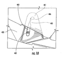
FIG. 10 is a detail view of the motion guide according to the example embodiment ofFIG. 8 after experiencing a frontal impact. -
FIG. 11 is an exploded view of a child safety seat according to an example embodiment of the present invention; and -
FIG. 12 is a section view of a child safety seat according to an example embodiment of the present invention. - The present invention will be described more fully hereinafter with reference to the accompanying drawings, in which some, but not all embodiments of the inventions are shown. Indeed, these inventions may be embodied in many different forms and should not be construed as limited to the embodiments set forth herein; rather, these embodiments are provided so that this disclosure will satisfy applicable legal requirements. Like numbers refer to like elements throughout. The terms top, bottom, side, up, down, upwards, downwards, vertical, horizontal, and the like as used below do not imply a required limitation in all embodiments of the present invention but rather are used herein to help describe relative direction or orientation in the example embodiments illustrated in the figures. The drawings omit illustration of certain energy absorbing materials, padding, fabric, and other coverings to facilitate ease of visibility and understanding of features of the invention.
- Various embodiments of the present invention provide a child safety seat configured for attachment to a seat in a variety of vehicles. The child safety seat may be configured for installation in a forward-facing position or in a rearward-facing position to accommodate children in the appropriate position based on the height and weight of a child, such as according to the guidelines and standards of the United States National Highway Transportation Safety Administration (NHTSA) and similar authorities in other countries.
- As illustrated in
FIG. 1 , thechild safety seat 100 may include aseat portion 110 also referred to as a seat shell pivotably coupled to abase 120. Theseat portion 110 andbase 120 may pivot relative to each other, for example, to ensure a desired angle of recline for a child secured within the seat in the forward-facing or rearward-facing positions. As different vehicles have different seat configurations, the child safety seat may have an adjustable recline such that the base 120 may be situated squarely on thevehicle seat 200 while theseat portion 110 may be adjusted to a desired recline angle by pivoting or rocking on the base. Optionally, the base may be fixed to the seat portion or a unitary part of the seat portion and the base configured with an adjustment to achieve a desired angle in the installed position. - Positioning a child properly in a child safety seat is important to minimize the adverse affect an impact may have on an occupant of the child safety seat. Positioning includes the proper attachment of the safety seat to the vehicle and setting the angle of the
seat portion 110 of the safety seat. Positioning the safety seat is also desirable to ensure the occupant maintains a proper seating position in the seat, such as when asleep. - The
seat portion 110 may define aseating area 115 that includes a bottom 117 and aback 119. The seating area may further include aharness 150 to secure a child within the seat. The harness may include abuckle 152 and twostraps buckle 152 when the harness is fastened. Thestraps adjustment strap 156 for tightening (i.e. shortening) of theharness 150 around an occupant of the seat. - The
buckle strap 153 that attaches thebuckle 152 to the seat may be configured to extend from anopening 157 in thebottom 119 of the seat between the legs of an occupant of the safety seat as illustrated further inFIG. 2 , which illustrates a view of theseating area 115 of theseat portion 110 as viewed from above the seat. Thebuckle strap 153 may be configured to be adjustable between distinct positions within thebottom 117 of the seat. The example embodiment ofFIG. 2 shows that theopening 157 through which thebuckle strap 153 extends in a relatively lateral configuration may also include alongitudinal repositioning portion 158 and at least a second relativelylateral opening 159. Thebuckle strap 153 may be made of a flexible webbing and may be adjusted by manipulating the flexible webbing from the firstlateral opening 157, through thelongitudinal repositioning opening 158, and into the secondlateral opening 159. The adjustability of thebuckle strap 153 may benefit an occupant by being positioned closer to the occupant allowing a tighter, more secure fit around the occupant. While a two-position adjustment is illustrated and described, three or more adjustable positions may be possible using similar configurations. - The safety seat may further include an
energy absorbing material 148 that lines at least a portion of theseating area 115 shown inFIG. 1 . Theenergy absorbing material 148 within theseating area 115 may be arranged to minimize the trauma sustained by an occupant of the safety seat during an impact when a body part, such as a head, shoulder, or hip, impacts the side of theseating area 115. Theenergy absorbing material 148 may be any known or future developed or discovered energy absorbing material such as including foam rubber (e.g. neoprene) and expanded polystyrene (EPS), or expanded polypropylene (EPP) among others. Additional energy absorbing material may be provided in regions which an occupant's head may contact during an impact. - The
safety seat 100 may further include padding provided for comfort and/or safety of the occupant. Such padding may be attached to theseating area 115 of thesafety seat 100 and/or the padding may be included in a cover that is provided-to cover theseat 110 and provide an aesthetically pleasing exterior with colors or patterns. - The
child safety seat 100 may be installed in a vehicle seat, such as by use of the vehicle seat-belt, a Lower Anchors and Tethers for Children (LATCH) system, or an ISOFix system. For example, LATCH attachment points have been standard on vehicles manufactured after September 1, 2002 for sale in the U.S. and are intended to accommodate all child safety seats sold in the U.S. The LATCH attachment points typically include a metal anchor that is securely and permanently fastened to a structural member of the vehicle thereby providing a secure anchor point for attachment of the safety seat. - As illustrated in the example embodiments of
FIGS. 1 ,3 , and4 , the child safety seat is attached to thevehicle seat 200 through the use of LATCH attachment straps 130. A first end of theattachment strap 130 includes aLATCH connector 172, while a second end of the attachment strap is secured to thesafety seat 100. TheLATCH connector 172 may be secured to aLATCH attachment point 170 of the vehicle. Alternative means for installing the safety seat will be detailed further below. Atether 140 may be included that is secured at one end to the top-portion of thesafety seat 142 and at the other end to atether anchor 144 that is permanently secured to the vehicle as shown inFIGS. 1 and3 . - Child safety seats are frequently moved in and out of vehicles such that a low-weight safety seat may be desirable for portability while maintaining the structural rigidity necessary for safety. Further, LATCH attachment points are rated for a maximum weight such that reducing the weight of the seat may increase the permissible weight of a child that may be secured in the seat while attached to the LATCH anchors and adhering to the maximum rated weight. In view of the above, the
seat portion 110 may be formed of a light-weight plastic or composite. Theseat portion 110 may be made of a single piece of molded material or possibly separate pieces for the back 119 andbottom 117. Theseat portion 110 may not have the necessary structural rigidity necessary for adequately securing the seat within a vehicle or for adequate protection of an occupant. Therefore, the safety seat may include additional structural support to provide added rigidity to theseat portion 110 for proper installation and adequate occupant protection. The safety seat may include aseat support 180 made of a rigid material that is attached to theseat portion 110. Theseat support 180 may be a frame or portion of a frame that at least partially surrounds theseat portion 110 and provides rigidity to the seat portion and attachment points for installation within a vehicle. As defined herein and by comparison to the prior art, theseat support 180 is not solely an attachment means for installing the safety seat in a vehicle, but rather a structural element that enhances the rigidity of theseat portion 110 while also serving as a secure location for attachment to a vehicle. Seat supports according to embodiments of the present invention reduce or eliminate the need for large plastic supports that are often used in the prior art to provide structural rigidity to a safety seat and that are located behind and below the seat shell. - A side view of an example embodiment of the present invention is illustrated in
FIG. 3 . The side view illustrated is substantially a mirror image of the opposite side such that references herein are made to like elements on both sides of the safety seat. As shown, theseat support 180 extends at least partially adjacent each side of theseat portion 110 with the bottom 117 therebetween, as compared to extending below thebottom 117 of the seat portion as in the state of the art (i.e., between the bottom 117 and the vehicle seat). Theseat support 180 may extend below theseat bottom 117; however, this may prevent theseat bottom 117 from being situated as close to the vehicle seat as desired. By virtue of the seat support extending at least partially adjacent to the sides of theseat portion 110 with the bottom 117 therebetween, theseat portion 110 may be situated lower with respect to the vehicle seat. Additionally, the seat supports 180 extending at least partially adjacent to the sides of theseat portion 110 may provide a rigid attachment point for the lower attachment straps 130. - In the illustrated embodiment of
FIG. 3 , theseat support 180 is securely attached to theseat portion 110 atpoint 184 on a first side of the seat. The seat support extends frompoint 184 adjacent to thebottom 117 of theseat portion 110. The seat support further extends along the back 119 of the seat portion where it may be attached to the base. Theseat support 180 may be at least partially enclosed by theseat portion 110 as illustrated beginning at 182. Further, theseat support 180 may extend across the back 119 of theseat portion 110 and meet the seat support on the opposite side of the safety seat in a mirror image configuration of the seat support on the first side of the seat. The seat support may be a single, unitary element such as a single metal tube or bar that extends frompoint 184 adjacent to the bottom 117, along the back 119, adjacent the opposite side of the bottom 117, and terminate at a point opposite of 184. Alternatively, theseat support 180 may include two individual support members that each extend on a respective side frompoint 184 adjacent to thebottom 117 of theseat portion 110 and extend along the back 119 of theseat portion 110. In an example embodiment wherein theseat support 180 includes two individual support members, said support members may be identical parts constructed such that either support member could be used on either side of the safety seat. Theseat support 180 of either aforementioned embodiment may extend along the back 119 of the seat portion, for example, at least as far as the top of the harness that would engage the shoulders of an occupant. Optionally, theseat support 180 may extend across the seatproximate point 184 at the front of the seat such that the support passes under the leg path of an occupant. - According to an example embodiment of the present invention wherein the
seat support 180 is arranged on the side of theseat portion 110, adjacent theseat bottom 117, theseat bottom 117 may extend below the seat support as illustrated at 121. Lowering thebottom 117 of the seat helps to lower the center of gravity of thesafety seat 100. Lowering the center of gravity of the seat may improve the safety seat performance during an impact as will be described further below. - The lower attachment straps 130 may be configured to attach to the
seat support 180 at any point along the length. The seat support may be configured with twobends bend seat support 180 may include a relatively smooth surface to permit sliding of theattachment strap 130 on the seat support and into abend FIG. 3 , the lower attachment straps 130 will move towards and intobend 176 as the attachment straps are tightened. When the safety seat is installed in a rearward-facing position, as shown inFIG. 4 , the lower attachment straps 130 will move towards and intobend 174 as the attachment straps are tightened. Desired attachment strap location may be a critical factor in occupant safety and mitigating adverse effects of an impact. Additionally, since theseat support 180 is unimpeded between thefirst bend 174 and thesecond bend 176, theattachment strap 130 may be moved between the forward-facing installation position and the rearward-facing installation position without removal of the attachment straps from the safety seat. This feature, together with strategically configured and located bends, may help to prevent common installation errors by a user. - Example embodiments of a safety seat according to the present invention may further include
safety belt pathways seat portion 110 to facilitate securing the safety seat in a vehicle using the vehicle safety belt or an attachment belt that includes latch connectors on both ends. Referring toFIG. 3 ,safety belt pathway 190 includes two apertures, one on each side of theseat portion 110 proximate theseat bend 176, for insertion of a safety belt through a first side of theseat portion 110 and out through the other side of theseat portion 110. Thesafety belt pathway 190 may be configured to accept a lap-belt only, a lap-belt and shoulder-belt doubled together, or an attachment belt with latch connectors at either end. When installed using a safety belt or attachment belt, the belt of the vehicle passes over theseat support 180 such that when the belt is fastened, theseat support 180 is secured to the vehicle. This configuration applies the tension of the safety belt or attachment belt to the seat support and may prevent applying significant tension or force to theseat portion 110 of thesafety seat 100. - Similarly, with regard to
FIG. 4 , asafety belt pathway 192 for the rearward-facing position extends through thesafety seat 110 proximate thesecond bends 174 for use when the safety seat is installed in the rear-facing position with a safety belt. As with the forward-facing safety belt installation, the safety belt extends over theseat support 180 such that tension applied to the belt is exerted on theseat support 180 in addition to theseat portion 110. - Referring again to
FIG. 2 , the safety seat may includesafety belt pathways FIGS. 3 and4 . Between the apertures in theseat 110 that define each of thepathways seat portion 110 and retain the safety belt in a desired location. The seat-belt lock-offs seat portion 110. The second piece may be a locking portion that hingedly attaches to the integrally molded recess. In the open position, the safety belt may be placed across the recess. In the closed position, the safety belt is secured by the locking portion in the seat-belt lock-off 191, 193. The locking portion may securely snap in to the recess when in the closed position. The recess portions may optionally be separately molded and installed into the seat portion. The locking portions and/or the recess portions may be made of a different color material than theseat portion 110 to alert the user of their presence and to clearly differentiate the locking portions from theseating area 115. For example, the seat-belt lock-offs seat portion 110 to attract the attention of a user and indicate the significance of such a part. - As previously noted in accordance with some embodiments of the present invention, the
seat support 180 located adjacent to theseat portion 110 allows thebottom 117 of the seat portion to be configured in a lower position with respect to thebase 120. Whether the safety seat is attached to the vehicle via the safety belt or the lower anchor attachment points, thesafety seat 100 is substantially fixed at a point that is low on the seat, generally between thelower seat cushion 201 and the back seat cushion 202 (seeFIG. 1 ). An example of the benefit of a lower center of gravity is illustrated inFIGS. 5A and 5B . The safety seats ofFIGS. 5A and 5B are included only to provide visual references and are not intended to illustrate actual measurements.FIG. 5A illustrates a state-of-the art child safety seat that includes a higher center ofgravity 311 whereasFIG. 5B illustrates a child safety seat according to an example embodiment of the present invention that includes a lower center ofgravity 301. The X and Y coordinate moment arms of each embodiment (302, 303 and 312, 313) are frompoints FIGS. 5A and 5B illustrate the child safety seat in a forward-facing position, the same geometry regarding the center of gravity and rotation about the fixed point holds true for the rearward-facing position. - Multiple features of embodiments of the safety seat of the present invention are configured to allow for and encourage the desired movements or kinematics of the seat to decrease impact forces experienced by an occupant of the seat as described further below. As noted above, during a frontal impact involving a forward-facing child safety seat, forward rotation of the child safety seat may cause head excursion of an occupant of the safety seat. As the forward rotation of the child safety seat is normally undesirable, it would be preferable for the bottom rear of the
seat portion 110 to advance down and/or forward during a frontal impact to reduce rotation. The location of the attachment points 174, 176 on thesafety seat 110 from which the attachment straps 130 extend may help to minimize or reduce the amount of forward rotation experienced by asafety seat 110 and an occupant during a frontal impact. Translating the forward rotational motion of a safety seat into a downward motion may benefit a safety seat occupant by reducing head excursion and altering the forces exerted on an occupant into a direction that is better tolerated by the body of an occupant, resulting in a lower likelihood of injury. - The location of the attachment straps 130 along the
seat support 180 at thebends FIG. 6 . During a frontal impact, the safety seat would tend to travel forward (arrow 330) as the vehicle experiences abrupt deceleration where deceleration is the change in velocity as measured over time. The length of theattachment strap 130 is fixed when installed in a vehicle. As the seat is urged forward by the impact, theattachment point 170, fixed within the vehicle, remains stationary relative to the vehicle. Thus, theattachment strap 130 is pulled forward in the direction ofarrow 330. As the attachment strap is pulled forward, the strap may only travel along the radius defined by the fixed length of the strap and shown byarrow 340. Therefore, as the safety seat continues forward, the strap is urging the seat downward, along the radius defined by the length of thestrap 340, thus urging the bottom of theseat 310 towards thebase 320. -
FIG. 7 illustrates the forces involved in an example embodiment of the present invention in which the child safety seat is installed in a rearward-facing position. When installed in a rearward-facing position, the safety seat is typically more reclined with respect to the base or vehicle seat. If a safety seat in a rearward-facing position is subject to a frontal impact, the seat is urged forward by the impact alongarrow 360 and theattachment point 170 remains stationary with respect to the vehicle. The motion of theseat 310 in the direction ofarrow 360 results in the attachment strap being pulled forward and traveling along the radius defined by the length of thestrap 130. Since thebend 174 that locates the point of attachment for theattachment strap 130 in the rearward-facing position is lower (with respect to the attachment point 170) than thebend 176 that locates theattachment strap 130 in the forward-facing position, the downward motion of thestrap 130 generated by the frontal impact is less than in the forward-facing position. The resultant downward force of theseat 310 into the base 320 in a frontal impact for the rearward-facing safety seat is lower than the comparable force in the forward-facing position. -
FIG. 8 illustrates the side view of a safety seat illustrated without theseat support 180 according to an example embodiment of the present invention. Theseat support 180 is omitted for ease of illustration and clarity of understanding features obstructed by theseat support 180. Thebase 400 of the illustrated embodiment includes amotion guide 401 which also functions as a crash indicator. Themotion guide 401 is configured to guide the motion of theseat portion 420 when installed in a forward-facing position during a frontal impact and provide a visual indication to a user that the child safety seat has been involved in an impact and the performance or safety of the seat may be compromised. -
FIG. 9 illustrates a detail view of amotion guide 401 according to an example embodiment of the present invention. Themotion guide 401 is configured to carry apin 402 within agroove 403 of themotion guide 401. Thepin 402 is attached to theseat portion 420 such that thepin 402 andseat portion 420 move in unison. Thepin 402 is configured to rest upon a motion inhibitor orridge 405 within thegroove 403. Upon experiencing a frontal impact of sufficient force when the seat is in a forward-facing position, thepin 402 is urged past theridge 405 and through thegroove 403. While the illustrated embodiment shows thepin 402 coupled to the movement of theseat portion 420 while themotion guide 401 is fixed relative to thebase 400, the converse may function equally well. Themotion guide 401 may be coupled to theseat portion 420 while thepin 402 may be coupled to thebase 400. - The
motion guide 401 and thepin 402 may be visible from the side of the safety seat. The pin may be colored or include a cap made of metal or of another material or color that increases visibility of the pin when viewed from the side of the safety seat. This may allow a user to more easily view the location of thepin 402 within themotion guide 401. Once the safety seat has experienced a frontal impact in a forward-facing position sufficient to cause thepin 402 to pass over theridge 405 and through thegroove 403, the unseated position of the pin or cap within thegroove 403 visibly indicates that the safety seat has experienced a significant impact as illustrated inFIG. 10 . Once a safety seat has experienced a significant impact, the materials and attachment points may be weakened and compromise the future performance of the safety seat. Themotion guide 401 may therefore provide a visual indication that the safety seat should no longer be used. - The direction of the force caused by a frontal impact when the child safety seat is in the forward-facing position may cause the
pin 402 to travel towards the direction of thearrow 450 ofFIG. 9 as the seat is caused to pivot aboutaxis 410 as shown inFIG. 8 . When the frontal impact causes the seat to experience a force above a predetermined threshold in the direction ofarrow 450, the force causes thepin 402 to pass over theridge 405 and through thegroove 403. The ridge may help to prevent motion of thepin 402 into thegroove 403 during an event, such as a hard braking event, that is unlikely to cause injury to an occupant of the vehicle. In such a hard braking event or mild "fender-bender" type impact, such as a frontal impact in which the vehicle airbags do not deploy, the force may be below the predetermined threshold and not be sufficient to cause thepin 402 to pass over theridge 405. During a frontal impact causing sufficient force to dislodge the pin from therecess 406, the motion of thepin 402 at least partially through thegroove 403 translates into theseat portion 110 pivoting around anaxis 410 proximate the front of the base (shown inFIG. 8 ) and theseat bottom 117 moving down towards the vehicle seat bottom and towards or into thebase 400.Axis 410 corresponds to a fixed forward position of the seat shell relative to the base, which may be adjusted if the seat shell is configured to recline, such as for a rear-ward facing position. The movement of thepin 402 at least partially through thegroove 403, as illustrated inFIG. 10 , translates at least a portion of the forward motion resulting from the impact into a downward motion into thesafety seat base 400. During a frontal impact when the safety seat is installed in a forward-facing position, themotion guide 401, together with theappropriate location 176 of the attachment straps 130 along theseat support 180, encourage a downward motion of the seat into the base reducing the rotational motion of the seat and better protecting an occupant from injury. - Referring again to
FIG. 9 , theridge 405 of themotion guide 401 may serve a separate purpose when the child safety seat is installed in a vehicle in the rearward-facing position as compared to the function in the forward-facing position described above. When the safety seat is installed in the rearward-facing position, a frontal impact may cause the pin to be forced deeper in to therecess 406 along the path of arrow 460 (as the seat portion is caused to pivot around axis 410). The kinematics of theseat 420 in the forward-facing position are different than the kinematics of the seat in the rearward-facing position such that motion of thepin 402 through thegroove 403 may not be necessary, or may be undesirable for the performance of the safety seat. The shapes ofrecess 406 andridge 403 may be configured to retain thepin 402 alongpath 460 in the rearward-facing position, rather than allowing thepin 402 to move alonggroove 403. - A safety seat according to various embodiments of the present invention may further include an additional safety feature to reduce the likelihood of injury to an occupant of the safety seat when the seat is installed in a forward-facing position. As noted above, translating the forward motion resulting from a frontal impact into a substantially downward motion with respect to the vehicle seat may reduce head excursion from the safety seat, reducing the likelihood of injury. It may also be desirable to both translate the forward motion of the frontal impact into a downward motion and simultaneously reduce the rate of deceleration of the seat, thereby reducing the force observed by an occupant of the seat. To this end, safety seats according to embodiments of the present invention may be further configured with an energy absorption feature with mechanisms and component members arranged to reduce the forces observed by an occupant of the safety seat caused by a frontal impact when the safety seat is in a forward-facing position. As force is equal to an object's mass multiplied by the acceleration of the object, a reduction in the acceleration (or negative acceleration, also called deceleration) will reduce the force on the object. During an impact, the change in velocity of the vehicle will be equal to the change in velocity of the safety seat and as they are attached to one another. While the change in velocity is equal, deceleration is not necessarily equal since deceleration is the change in velocity over time as noted above. Thus, altering the time or duration of the change in velocity will alter the rate of deceleration (i.e., increasing the duration of the change in velocity will decrease the rate of deceleration). As such, it may be desirable to extend the duration of the change in velocity as observed by the
seat 310 and an occupant therein, thereby reducing the deceleration and thus the force. -
FIG. 11 illustrates an exploded view of a safety seat with an energy absorbing feature according to an example embodiment of the present invention. The depicted embodiment includes aseat 310 with aseat bottom 317, abase 320 and acavity 340 defined therebetween. Thecavity 340 is configured to receive an energy absorbing feature, such as the depictedenergy absorbing members energy absorbing members cavity 340 between the base 320 and theseat 310. Eachenergy absorbing member top surface bottom surface - It may be desirable for the
energy absorption members base 320, along abottom surface energy absorption member seat bottom 317, along atop surface energy absorption member seat 310 advancing into thebase 320 and minimize the peak force (e.g., by reducing the maximum rate of deceleration) observed by the seat 310 (and thereby an occupant thereof), locating the energy absorbing material close to or in contact with thebase 320 and theseat bottom 317 may reduce or eliminate a momentary spike in the acceleration of theseat 310 as it advances from a non-contact position to a contact position. For example, the greater the distance between theseat bottom 317 and theenergy absorbing members seat bottom 317 before contacting theenergy absorbing material -
FIG. 12 illustrates a cross-section of a safety seat incorporating various features of the present invention. As depicted, thetop surface 502 of theenergy absorbing member 500 is in contact with theseat bottom 317. Thetop surface 502 of theenergy absorbing member 500 includes a concave curvature that is configured to cradle and support the convex curvature of theseat bottom 317, thereby increasing the contact area between theseat bottom 317 and theenergy absorbing member 500. The concave curvature of thetop surface 502 of theenergy absorbing member 500 also allows theseat 310 to be moved between angles of recline relative to the base while maintaining contact with thetop surface 502 of theenergy absorbing member 500. In the example embodiment ofFIG. 12 , a recline mechanism is depicted that includes achannel 602 and abar 604 that defines an axis. Thebar 604 is disposed within thechannel 602 and is configured to remain fixed within thechannel 602 until the recline handle 606 is pulled. When the recline handle 606 is pulled, thebar 604 may travel within thechannel 602, which may be an arcuate radius about a point proximate to the of middle of the concave curvature of thetop surface 502 of theenergy absorbing member 500. Such a configuration may allow theseat bottom 317 to rotate with respect to theenergy absorbing member 500 while maintaining surface contact with thetop surface 502 of theenergy absorbing member 500. Further, thebar 604 may be the axis about which theseat 310 rotates (reference number 410 ofFIG. 8 ) when the seat is installed in a forward-facing position and experiences a frontal impact. - As depicted in
FIG. 12 , thebottom surface 504 of theenergy absorbing member 500 is in contact with thebase 320. The base may include attachment points 322, 324 configured to receive theenergy absorbing member 500 and maintain the position of theenergy absorbing member 500 within the base during normal use and during an impact. It may be desirable for the contact areas between thebottom surface 504 and thebase 320 and between thetop surface 502 and theseat 310 to be of sufficient area to minimize the pressure exerted on thetop surface 502 andbottom surface 504 of theenergy absorbing member 500. As pressure is equal to a force per unit of area, increasing the contact area while maintaining the same force results in a reduction of pressure. Reducing the pressure exerted on the surface of theenergy absorbing member 500 may allow the energy to be more evenly distributed throughout theenergy absorbing member 500 which may improve their effectiveness. Thus, a contact area that extends from thefront 506 of theenergy absorbing member 500 to the back 508 of theenergy absorbing member 500 may reduce the pressure exerted on theenergy absorbing member 500 during an impact and more evenly distribute the energy throughout theenergy absorbing member 500. - The
energy absorbing member 500 ofFIG. 12 and themotion guide 401 ofFIG. 9 may function in a cooperative manner to reduce the forces experienced by an occupant of the safety seat during a frontal impact when the safety seat is installed in a forward-facing position as described herein. While the following description is directed to asingle motion guide 401 and a singleenergy absorbing member 500, it is to be appreciated that the safety seat may include motion guides on each side of the seat and multiple energy absorbing members may be used. Theseat bottom 317 may be configured to be in contact with thetop surface 506 of theenergy absorbing member 500 while thepin 402 of themotion guide 401 is above theridge 405. During normal use (i.e., installed in a vehicle and occupied by a child), theenergy absorbing members 500, in cooperation with themotion guide 401 maintain thepin 402 above theridge 405. While theenergy absorbing members 500 may provide support to theseat 310 during normal use, the amount of force exerted upon theenergy absorbing member 500 during normal use is not sufficient to deform them. Similarly, during installation and removal of the safety seat and during hard-braking events or very minor impacts, the threshold amount of force required to move thepin 402 past theridge 405 and to deform theenergy absorbing member 500 may not be achieved. - During an impact, when the safety seat is installed in a vehicle in a forward-facing position, the attachment straps resist the forward movement of the seat. By virtue of their radius of rotation described above with reference to
FIG. 6 , the attachment straps are configured to apply a force to theseat 310 about the axis of therecline bar 604 in the direction ofarrow 450 ofFIG. 9 . If the frontal impact is of sufficient force, the force applied to theseat 310 by the attachment straps alongarrow 450 may exceed the threshold required to begin the deformation of the energy absorbing member(s) 500 and urge thepin 402 past theridge 405 of themotion guide 401. The force in the direction ofarrow 450 further moves thepin 402 at least partially through thegroove 403 as theseat bottom 317 further deforms the energy absorbing member(s) 500. The motion of theseat 310, as guided by the attachment straps andmotion guide 401 is substantially vertically down with respect to thebase 320. - As will be appreciated by one of ordinary skill in the art, without the
energy absorbing members seat base 317 reaches its maximum downward travel point within thecavity 340. Theenergy absorbing members seat 310 and reducing the likelihood of a relatively brief duration, high deceleration rate impact which is more likely to cause injury to an occupant of the safety seat. A slower rate of deceleration may also reduce the maximum head excursion experienced by an occupant of the safety seat. - The
energy absorbing members FIG. 12 ), a closed cell structure, an air-bag, a fluid filled damper or shock absorber, or other structures known in the art. The materials used may include a deformable plastic, foam, rubber, or metal among others. The material may be selected for elastic deformation or for plastic deformation. However, it may be preferable to select a material that will not return to the original shape after experiencing an impact. - Many modifications and other embodiments of the inventions set forth herein will come to mind to one skilled in the art to which these inventions pertain having the benefit of the teachings presented in the foregoing descriptions and the associated drawings. Therefore, it is to be understood that the inventions are not to be limited to the specific embodiments disclosed and that modifications and other embodiments are intended to be included within the scope of the appended claims. Although specific terms are employed herein, they are used in a generic and descriptive sense only and not for purposes of limitation.
Claims (24)
- A safety seat comprising:a base; anda seat including a bottom and configured with an axis connecting the base and the seat;wherein the base and seat define a cavity disposed therebetween; and wherein the seat bottom is configured to rotate about the axis and advance into the cavity during a frontal impact.
- The safety seat of claim 1, wherein the forward direction of the seat is defined by the direction an occupant of the safety seat is facing and the axis is disposed forward of the cavity.
- The safety seat of claim 1, further comprising an energy absorbing member disposed within the cavity, wherein the energy absorbing member is configured to be deformed as the seat bottom advances into the cavity during the frontal impact.
- The safety seat of claim 3, wherein the energy absorbing member is deformed by substantially vertical movement of the seat bottom into the cavity.
- The safety seat of claim 1, wherein the base and the seat are configured with a motion guide to direct the motion of the seat bottom along a path into the cavity during the frontal impact.
- The safety seat of claim 5, wherein the path of the seat bottom with respect to the base is substantially perpendicular to the direction of the frontal impact.
- The safety seat of claim 5, wherein the motion guide includes a motion inhibitor that precludes motion of the seat bottom along the path when force from the frontal impact is below a threshold value.
- The safety seat of claim 5, wherein the motion guide is fixed relative to the base and includes a groove, wherein the seat includes a pin that is fixed relative to the seat, wherein the pin is arranged within the groove, and wherein the pin and the groove cooperate to define the path of the seat bottom into the cavity during the frontal impact.
- The safety seat of claim 5, wherein the motion guide is configured to provide a visual indication of the seat bottom moving along the path into the cavity during a frontal impact.
- The safety seat of claim 1, wherein the seat is pivotally coupled to the base about the axis and the seat is configurable between at least two angles of recline with respect to the base.
- The safety seat of claim 3, wherein the energy absorbing member disposed within the cavity is configured to allow the seat to adjust between at least two angles of recline with respect to the base.
- The safety seat of claim 11, wherein a top surface of the energy absorbing member includes a concave curvature and wherein the concave curvature is configured to cradle the convex curvature of the bottom of the seat.
- A safety seat comprising:a base; anda seat including a bottom;wherein the base and seat define a cavity disposed therebetween;wherein the seat bottom is configured to advance into the cavity during a frontal impact producing a force when the safety seat is installed in a vehicle in a forward-facing position; andwherein the seat is configured to attach to a vehicle by at least one strap.
- The safety seat of claim 13, wherein the at least one strap is configured to restrict the motion of the seat during a frontal impact and cause the seat bottom to advance towards the cavity when the safety seat is installed in a forward-facing position.
- The safety seat of claim 13, further comprising energy absorbing member disposed within the cavity, wherein the energy absorbing member is configured to be deformed as the seat bottom advances into the cavity.
- The safety seat of claim 13, wherein the seat bottom is configured to remain fixed relative to the base during a frontal impact when the safety seat is installed in a vehicle in a rearward facing position.
- The safety seat of claim 13, further comprising a motion guide configured to direct motion of the seat bottom into the cavity during the frontal impact and wherein the motion guide comprises a pin ridge that prevents the seat bottom from advancing into the cavity when the force of the frontal impact is below a threshold value.
- A safety seat comprising:a seat including a bottom;a base;an energy absorbing member disposed between the bottom of the seat and the base; anda motion guide configured to direct the bottom of the seat into the energy absorbing member and deforming the energy absorbing member during a frontal impact when the safety seat is installed in a vehicle in a forward-facing position and wherein the motion guide is configured to preclude the bottom of the seat from deforming the energy absorbing member during a frontal impact when the safety seat is installed in a vehicle in a rearward-facing position.
- The safety seat of claim 18, wherein the motion guide is further configured to prevent the bottom of the seat from deforming the energy absorbing member during a frontal impact producing a force below a threshold value.
- The safety seat of claim 18, further comprising attachment straps that attach the seat to the vehicle and cooperate with the motion guide to direct the bottom of the seat into the energy absorbing member during a frontal impact.
- A method of reducing the effects of a frontal impact on an occupant of a safety seat, the safety seat defining a seat, a base, and a cavity disposed therebetween, the method comprising:attaching the seat to a fixed location within a vehicle;directing motion of the seat into the cavity during a frontal impact; andcompressing an energy absorbing member disposed within the cavity.
- The method according to claim 21, wherein the directing motion of the seat into the cavity comprises advancing a pin of a motion guide past a motion inhibitor and directing the pin of the motion guide through at least a portion of a groove of the motion guide.
- The method according to claim 21, wherein compressing the energy absorbing member includes extending the duration of the motion of the seat into the cavity.
- The method according to claim 21, wherein the attaching the seat to a fixed location within a vehicle comprises attaching the seat to the fixed location within the vehicle with an attachment strap.
Applications Claiming Priority (1)
| Application Number | Priority Date | Filing Date | Title |
|---|---|---|---|
| US12/725,907 US8348337B2 (en) | 2010-03-17 | 2010-03-17 | Child safety seat with energy absorbing apparatus |
Publications (2)
| Publication Number | Publication Date |
|---|---|
| EP2368753A1 true EP2368753A1 (en) | 2011-09-28 |
| EP2368753B1 EP2368753B1 (en) | 2016-11-16 |
Family
ID=43923575
Family Applications (1)
| Application Number | Title | Priority Date | Filing Date |
|---|---|---|---|
| EP11001951.0A Active EP2368753B1 (en) | 2010-03-17 | 2011-03-09 | Child safety seat with energy absorbing apparatus |
Country Status (7)
| Country | Link |
|---|---|
| US (1) | US8348337B2 (en) |
| EP (1) | EP2368753B1 (en) |
| JP (1) | JP5420579B2 (en) |
| KR (1) | KR101332737B1 (en) |
| CN (1) | CN102189946B (en) |
| AU (1) | AU2011200691B2 (en) |
| ES (1) | ES2615859T3 (en) |
Cited By (3)
| Publication number | Priority date | Publication date | Assignee | Title |
|---|---|---|---|---|
| WO2013061308A3 (en) * | 2011-10-27 | 2013-08-01 | Leatt Corporation | Child restraint system |
| WO2021055337A1 (en) * | 2019-09-16 | 2021-03-25 | Monahan Products, LLC | Child carrier with side impact protection |
| US11511656B2 (en) | 2021-03-24 | 2022-11-29 | Monahan Products, LLC | Child restraint system with side impact bumper |
Families Citing this family (48)
| Publication number | Priority date | Publication date | Assignee | Title |
|---|---|---|---|---|
| WO2008137156A2 (en) * | 2007-05-07 | 2008-11-13 | Rajasingham Arjuna Indraeswara | Occupant support system |
| US9440563B2 (en) * | 2007-05-07 | 2016-09-13 | Arjuna Indraeswaran Rajasingham | Occupant support system |
| WO2012034585A1 (en) * | 2010-09-14 | 2012-03-22 | Cybex Industrial Ltd. | Child seat |
| US9221366B2 (en) | 2011-06-02 | 2015-12-29 | Dorel Juvenile Group, Inc. | Energy-dissipation system |
| EP2758272B1 (en) * | 2011-09-22 | 2019-08-21 | Clek Inc. | Child safety seat |
| AU2013267054B2 (en) * | 2013-12-05 | 2017-07-13 | Dorel Australia Pty Ltd | Energy-dissipation system |
| USRE47971E1 (en) * | 2012-06-01 | 2020-05-05 | Dorel Juvenile Group, Inc. | Energy-dissipation system |
| US8960789B2 (en) * | 2012-06-13 | 2015-02-24 | F Delta T Llc | Child vehicle safety seat |
| US9211820B2 (en) | 2012-11-01 | 2015-12-15 | Graco Children's Products Inc. | Child safety seat with side impact energy redirection |
| KR101421876B1 (en) * | 2013-01-10 | 2014-07-22 | 이지현 | Front and Rear Two Way Type Clamp Device for ISOFIX Car Seat |
| US9487110B2 (en) | 2014-03-05 | 2016-11-08 | Pidyon Controls Inc. | Car seat |
| US8911015B2 (en) | 2013-03-05 | 2014-12-16 | Yochanan Cohen | Car seat |
| US10220734B2 (en) | 2013-03-05 | 2019-03-05 | Pidyon Controls Inc. | Car seat |
| US9061611B2 (en) | 2013-03-14 | 2015-06-23 | Phillip W. Love | Impact dispersal system for a child safety seat |
| CN203637613U (en) * | 2013-08-29 | 2014-06-11 | 好孩子儿童用品有限公司 | Energy-absorbing and vibration-reducing device for child car seat |
| US9499074B2 (en) * | 2013-10-25 | 2016-11-22 | Britax Child Safety, Inc. | Forward and rearward facing child seat with belt tensioning mechanism for improved installation |
| CN103692939B (en) * | 2013-11-26 | 2015-12-23 | 郑州宇通客车股份有限公司 | Energy absorption device and use the safety seat of this energy absorption device |
| WO2015176165A1 (en) * | 2014-05-21 | 2015-11-26 | Clek Inc. | Child safety seat |
| EP3158358B1 (en) * | 2014-06-17 | 2020-12-16 | Mobius Protection Systems Ltd. | Impact handling and ultrasound alerting methods |
| US9616782B2 (en) | 2014-08-29 | 2017-04-11 | Pidyon Controls Inc. | Car seat vehicle connection system, apparatus, and method |
| US10011199B2 (en) | 2014-10-30 | 2018-07-03 | Diono, Llc | Rear facing ride down safety seat |
| EP3023293B1 (en) * | 2014-11-20 | 2017-12-27 | Britax Römer Kindersicherheit GmbH | Child safety seat |
| CA2985645A1 (en) * | 2015-05-12 | 2016-11-17 | Pidyon Controls Inc. | Car seat and connection system |
| US10040377B2 (en) | 2015-05-27 | 2018-08-07 | Wonderland Nurserygoods Company Limited | Child safety seat |
| CA2930939C (en) | 2015-05-27 | 2019-02-26 | Wonderland Nurserygoods Company Limited | Child safety seat and support base thereof |
| CN105034871A (en) * | 2015-07-10 | 2015-11-11 | 苍安国 | Device for restraining child passenger on motor vehicle |
| US9487157B1 (en) * | 2015-07-10 | 2016-11-08 | Ford Global Technologies, Llc | Vehicle display assembly including an energy absorption element |
| US10086722B2 (en) * | 2015-10-30 | 2018-10-02 | Dorel Juvenile Group, Inc. | Child restraint |
| CN105620416A (en) * | 2016-01-28 | 2016-06-01 | 好孩子儿童用品有限公司 | Safety belt energy absorption device and automobile seat for children |
| US10518671B2 (en) * | 2016-09-15 | 2019-12-31 | Graco Children's Products Inc. | Car seat with energy managing frame |
| US10293713B2 (en) | 2016-10-19 | 2019-05-21 | Dorel Juvenile Group, Inc. | Child-restraint harness |
| CN107901801B (en) * | 2017-12-05 | 2023-06-09 | 杭州琴侣高新技术有限公司 | Light safety seat capable of damping and adjusting space for helping sleep |
| ES2864710T3 (en) * | 2017-12-14 | 2021-10-14 | Britax Roemer Kindersicherheit Gmbh | Child safety seat |
| CN114801923B (en) * | 2017-12-21 | 2023-12-15 | 宝钜儿童用品香港股份有限公司 | Automobile safety seat |
| CA3047971C (en) * | 2018-07-05 | 2023-06-27 | Britax Child Safety, Inc. | Multi-functional energy absorber |
| NO344434B1 (en) * | 2018-09-19 | 2019-12-09 | Torgersen Hans & Soenn | Child safety seat with side impact energy absorption |
| CA3126293A1 (en) * | 2019-01-10 | 2020-07-16 | Clek Inc. | Child safety seat with energy absorber |
| AU2020201572B2 (en) * | 2019-03-13 | 2021-11-25 | Britax Child Safety, Inc. | Child safety seat |
| US11603019B2 (en) * | 2019-06-17 | 2023-03-14 | Zoox, Inc. | Seat crush structure |
| EP4028284A4 (en) * | 2019-09-12 | 2023-10-25 | Wonderland Switzerland AG | Child restraint with rotating seat |
| EP4054891A4 (en) * | 2019-11-04 | 2023-12-13 | BabyArk LTD | Methods and systems for safety seat |
| WO2021090316A1 (en) | 2019-11-04 | 2021-05-14 | Babyark Ltd | Methods and systems for generating training and executing a model for detecting safety seat events |
| CN117068012A (en) | 2019-12-30 | 2023-11-17 | 宝钜瑞士股份有限公司 | child safety seat |
| CN111845493B (en) * | 2020-07-31 | 2024-04-12 | 南京理工大学 | Manual adjustment buffering isolation device for lightning protection seat of military vehicle and use method |
| US20220144406A1 (en) * | 2020-11-10 | 2022-05-12 | Bell Textron Inc. | Energy attenuating pod carrier system for vertical lift aircraft |
| EP4011691A1 (en) * | 2020-12-14 | 2022-06-15 | George TFE SCP | Child safety seat |
| US11427113B1 (en) * | 2021-04-21 | 2022-08-30 | Institute For Injury Research | Wrap-around shield |
| CN113665446B (en) * | 2021-08-20 | 2022-11-01 | 湖南富明户外运动股份有限公司 | Child safety seat with buffering function |
Citations (4)
| Publication number | Priority date | Publication date | Assignee | Title |
|---|---|---|---|---|
| EP0403853A2 (en) * | 1989-06-20 | 1990-12-27 | PEG Kinderwagen Vertriebs- und Service GmbH | Device and method for protecting a person, in particular an infant, in a motor vehicle |
| DE19604094A1 (en) * | 1996-01-25 | 1997-07-31 | Kurt Dipl Ing Stroeer | Arrangement for hanging and fixing of child seat in vehicle |
| WO2001038130A1 (en) * | 1999-11-26 | 2001-05-31 | Igc (Australia) Pty Ltd | Child safety seat |
| EP1209025A1 (en) * | 2000-11-18 | 2002-05-29 | Toshiya Yoshida | Safety device for car seat |
Family Cites Families (79)
| Publication number | Priority date | Publication date | Assignee | Title |
|---|---|---|---|---|
| US67A (en) * | 1836-10-24 | robert mayo and robert mills | ||
| US2102979A (en) * | 1934-11-26 | 1937-12-21 | Harry M Smith | Motor vehicle safety seat |
| FR823912A (en) * | 1937-07-05 | 1938-01-28 | Accessoires En Tube Pour Autom | Reclining seat back, especially applicable to vehicles |
| GB1039080A (en) * | 1965-06-15 | 1966-08-17 | George Grammer | Vehicle seat, especially for agricultural vehicles |
| US3767259A (en) * | 1971-10-07 | 1973-10-23 | P Blake | Child{3 s vehicle safety seat assembly |
| US3858930A (en) * | 1972-07-11 | 1975-01-07 | Donald A Calandra | Safety vehicle seat system and trigger means for the same |
| US3998291A (en) * | 1975-08-06 | 1976-12-21 | Edwin George Davis | Automotive safety seat |
| US3985388A (en) * | 1975-08-11 | 1976-10-12 | Uop Inc. | Vertically adjustable seat with energy absorbing means |
| US4033622A (en) | 1976-06-29 | 1977-07-05 | Hedstrom Co. | Infant's car seat |
| US4215900A (en) * | 1978-02-10 | 1980-08-05 | Joseph Coult | Child's safety seat for vehicles |
| US4662597A (en) * | 1982-06-01 | 1987-05-05 | Milsco Manufacturing Company | Suspension for vehicle seat |
| DE3422695C2 (en) * | 1984-06-19 | 1995-03-30 | Roemer Britax Autogurte Gmbh | Child restraint |
| US4826246A (en) | 1987-08-04 | 1989-05-02 | Spalding & Evenflo Companies, Inc. | Child safety seat |
| US5449218A (en) * | 1988-01-07 | 1995-09-12 | Life Force, Inc. | Vehicle safety device |
| US5462333A (en) | 1988-10-21 | 1995-10-31 | Life Forece Associates, Lp | Child safety seat |
| US5286085A (en) | 1989-06-30 | 1994-02-15 | Takata Corporation | Restraining protective seat for infants |
| JPH0721389Y2 (en) * | 1989-12-21 | 1995-05-17 | コンビ株式会社 | Auxiliary seat for vehicle |
| US5244252A (en) * | 1990-10-29 | 1993-09-14 | Hector Serber | Seat assembly and method |
| EP0639124A1 (en) * | 1991-07-19 | 1995-02-22 | Massachusetts Institute Of Technology | Safety seat |
| US5437494A (en) * | 1992-10-29 | 1995-08-01 | Life Force Associates, L.P. | Rearward moving seat |
| US5290089A (en) * | 1992-12-28 | 1994-03-01 | General Motors Corporation | Seat bellows energy absorber |
| DE4303247C2 (en) | 1993-02-04 | 1995-11-16 | Osann Design Entwicklungs Und | Child safety seat |
| NO300260B1 (en) * | 1993-05-05 | 1997-05-05 | Torgersen Hans & Soenn | Children's car seat |
| JP3295183B2 (en) * | 1993-06-30 | 2002-06-24 | アップリカ▲葛▼西株式会社 | Automotive child safety seat |
| GB9320169D0 (en) | 1993-09-30 | 1993-11-17 | Britax Excelsior | Child safety seat |
| US5567006A (en) * | 1993-10-01 | 1996-10-22 | Mccarthy; Joseph | Vehicle seat with articulated sections |
| US5639144A (en) | 1994-06-27 | 1997-06-17 | Ford Motor Company | Energy absorbing child seat fastener |
| US5551751A (en) * | 1994-07-12 | 1996-09-03 | Century Products Company | Reclining restraint (smart move) |
| US5468044A (en) | 1994-07-13 | 1995-11-21 | Hoover Universal, Inc. | Energy absorbing child seat |
| US5468045A (en) | 1994-07-28 | 1995-11-21 | Hoover Universal, Inc. | Energy absorbing child seat |
| US5609393A (en) * | 1994-10-28 | 1997-03-11 | Lisco, Inc. | Reclining mechanism for toddler seat |
| US6267441B1 (en) | 1995-03-20 | 2001-07-31 | Armando Otero | Child vehicle safety seat |
| AUPN386595A0 (en) * | 1995-06-29 | 1995-07-20 | Britax Child-Care Products Pty Ltd | Child safety seat with an anti-rebound support |
| US5695243A (en) | 1996-01-31 | 1997-12-09 | Indiana Mills And Manufacturing, Inc. | Child seat mount with anti-twist web mechanism |
| US5685603A (en) | 1996-03-05 | 1997-11-11 | Trw Vehicle Safety Systems Inc. | Apparatus with a child seat and an energy absorption mechanism |
| JP3442614B2 (en) * | 1996-06-07 | 2003-09-02 | 豊 井上 | Vehicle seat |
| US5664830A (en) * | 1996-11-19 | 1997-09-09 | Birgit S. Garcia | Child safety seat assembly |
| JPH11291799A (en) * | 1998-04-09 | 1999-10-26 | Combi Corp | Child seat |
| JP2000296734A (en) * | 1999-02-08 | 2000-10-24 | Aprica Kassai Inc | Youth safety seat for automobile, protector, child care utensil protector, child care utensil and newborn baby bed |
| DE19906547B4 (en) * | 1999-02-17 | 2004-03-25 | Innovint Einrichtungs Gmbh | Child seat for mobile use in an aircraft |
| US6454350B1 (en) * | 1999-05-26 | 2002-09-24 | Graco Children's Products Inc. | Infant car seat/carrier assembly and method of controlling an infant carrier position |
| US8251444B2 (en) * | 2005-04-25 | 2012-08-28 | Arjuna Indraeswaran Rajasingham | Vehicle occupant support |
| DE19946056A1 (en) * | 1999-09-25 | 2001-03-29 | Bayerische Motoren Werke Ag | Arrangement of a child seat on a vehicle seat |
| JP2001097086A (en) * | 1999-09-28 | 2001-04-10 | Combi Corp | Child seat |
| DE19951625C2 (en) * | 1999-10-26 | 2002-02-07 | Girsberger Holding Ag Buetzber | Seat with adjustable backrest and seat |
| US6517154B2 (en) | 2000-02-08 | 2003-02-11 | Takata Corporation | Shock-reducing restraint |
| US6450576B1 (en) | 2000-06-22 | 2002-09-17 | Mattel, Inc. | Universal attachment for child car seat |
| JP2002178811A (en) * | 2000-12-14 | 2002-06-26 | Takata Corp | Child seat device |
| US6592183B2 (en) | 2001-02-16 | 2003-07-15 | Cosco Management, Inc. | Vehicle anchor system for juvenile vehicle seat |
| US6623075B2 (en) | 2001-03-05 | 2003-09-23 | Britax Child Safety Inc. | Child safety seat |
| JP4902070B2 (en) * | 2001-08-22 | 2012-03-21 | コンビ株式会社 | child seat |
| DE10142984B4 (en) * | 2001-09-01 | 2005-02-24 | Keiper Gmbh & Co. Kg | Vehicle seat, in particular motor vehicle seat |
| US6739660B2 (en) * | 2002-02-11 | 2004-05-25 | David N. Dukes | Motorized remote controlled reclining child safety car seat |
| US6739659B2 (en) * | 2002-02-11 | 2004-05-25 | David N. Dukes | Motorized remote controlled reclining child car seat |
| US6739661B1 (en) * | 2002-07-15 | 2004-05-25 | David N. Dukes | Pivotable reclining child safety car seat |
| JP4090820B2 (en) | 2002-08-29 | 2008-05-28 | 本田技研工業株式会社 | Child seat mounting structure |
| US6767057B2 (en) | 2002-09-17 | 2004-07-27 | General Motors Corporation | Vehicle anchorage system for child seat |
| EP1403131A3 (en) * | 2002-09-27 | 2005-06-15 | Combi Corporation | Child car seat |
| US7021709B2 (en) | 2003-11-20 | 2006-04-04 | General Motors Corporation | Child restraint seat anchors with integrated child seat detectors |
| US20080303321A1 (en) | 2004-05-08 | 2008-12-11 | Britax Excelsior Limited | Base for a Child Safety Support |
| US7380878B2 (en) | 2004-05-28 | 2008-06-03 | Skjp Holdings, Llc | Compact folding seat |
| GB0413940D0 (en) | 2004-06-19 | 2004-07-28 | Britax Excelsior | Child safety seat |
| CA2572201A1 (en) | 2004-06-29 | 2006-01-12 | Kidnetik Corp. | Child restraint apparatus for a vehicle cross-reference to related applications |
| GB0510313D0 (en) | 2005-05-20 | 2005-06-29 | Britax Childcare Ltd | Child safety seat |
| WO2007003918A1 (en) | 2005-07-01 | 2007-01-11 | Britax Excelsior Limited | Child safety seat |
| ATE428600T1 (en) | 2005-07-01 | 2009-05-15 | Britax Excelsior | ITEM HOLDER |
| US7472952B2 (en) | 2005-09-09 | 2009-01-06 | Britax Child Safety, Inc. | Safety seat |
| JP2007099214A (en) | 2005-10-07 | 2007-04-19 | Takata Corp | Child seat |
| GB2444833B (en) * | 2006-12-12 | 2011-12-07 | Wonderland Nursery Goods | Reversible child car seat with separable base member |
| US7918501B1 (en) * | 2007-07-18 | 2011-04-05 | Dennis Hawkins Hanson | Vehicle safety seat |
| US7699393B2 (en) | 2007-10-03 | 2010-04-20 | Evenflo Company Inc. | Load limiting (energy management) child restraint seat |
| US7717506B2 (en) | 2007-12-12 | 2010-05-18 | Britax Child Safety, Inc. | Child restraint apparatus for vehicle |
| US8500196B2 (en) | 2008-04-15 | 2013-08-06 | Britax Child Safety, Inc. | Child seat having a crush zone |
| FR2930520B1 (en) * | 2008-04-28 | 2010-08-20 | Eurocopter France | ANTI-CRUSHING SEAT OF A VEHICLE |
| NO329442B1 (en) * | 2008-09-08 | 2010-10-18 | Hts Hans Torgersen & Sonn As | Device at a car child seat |
| IT1394316B1 (en) | 2009-05-06 | 2012-06-06 | Segrall S R L | SEAT TO TRANSPORT A CHILD IN A VEHICLE. |
| TW201107161A (en) | 2009-08-31 | 2011-03-01 | Wonderland Nurserygoods Hk Co | An infant/child safety seat and method of installing the same |
| US8905478B2 (en) * | 2010-03-17 | 2014-12-09 | Britax Child Safety, Inc. | Child safety seat with structural support |
| EP2412565B1 (en) | 2010-07-27 | 2016-03-02 | BRITAX RÖMER Kindersicherheit GmbH | Energy absorbing element for a child safety seat |
-
2010
- 2010-03-17 US US12/725,907 patent/US8348337B2/en active Active
-
2011
- 2011-02-17 AU AU2011200691A patent/AU2011200691B2/en not_active Ceased
- 2011-03-09 ES ES11001951.0T patent/ES2615859T3/en active Active
- 2011-03-09 EP EP11001951.0A patent/EP2368753B1/en active Active
- 2011-03-17 JP JP2011058978A patent/JP5420579B2/en active Active
- 2011-03-17 KR KR1020110024009A patent/KR101332737B1/en active IP Right Grant
- 2011-03-17 CN CN201110064412.8A patent/CN102189946B/en active Active
Patent Citations (4)
| Publication number | Priority date | Publication date | Assignee | Title |
|---|---|---|---|---|
| EP0403853A2 (en) * | 1989-06-20 | 1990-12-27 | PEG Kinderwagen Vertriebs- und Service GmbH | Device and method for protecting a person, in particular an infant, in a motor vehicle |
| DE19604094A1 (en) * | 1996-01-25 | 1997-07-31 | Kurt Dipl Ing Stroeer | Arrangement for hanging and fixing of child seat in vehicle |
| WO2001038130A1 (en) * | 1999-11-26 | 2001-05-31 | Igc (Australia) Pty Ltd | Child safety seat |
| EP1209025A1 (en) * | 2000-11-18 | 2002-05-29 | Toshiya Yoshida | Safety device for car seat |
Cited By (4)
| Publication number | Priority date | Publication date | Assignee | Title |
|---|---|---|---|---|
| WO2013061308A3 (en) * | 2011-10-27 | 2013-08-01 | Leatt Corporation | Child restraint system |
| WO2021055337A1 (en) * | 2019-09-16 | 2021-03-25 | Monahan Products, LLC | Child carrier with side impact protection |
| US11318867B2 (en) | 2019-09-16 | 2022-05-03 | Monahan Products, LLC | Child carrier with side impact protection |
| US11511656B2 (en) | 2021-03-24 | 2022-11-29 | Monahan Products, LLC | Child restraint system with side impact bumper |
Also Published As
| Publication number | Publication date |
|---|---|
| JP5420579B2 (en) | 2014-02-19 |
| AU2011200691B2 (en) | 2013-06-06 |
| JP2011195142A (en) | 2011-10-06 |
| US8348337B2 (en) | 2013-01-08 |
| KR101332737B1 (en) | 2013-11-25 |
| CN102189946B (en) | 2014-03-19 |
| EP2368753B1 (en) | 2016-11-16 |
| US20110227376A1 (en) | 2011-09-22 |
| CN102189946A (en) | 2011-09-21 |
| ES2615859T3 (en) | 2017-06-08 |
| AU2011200691A1 (en) | 2011-10-06 |
| KR20110104920A (en) | 2011-09-23 |
Similar Documents
| Publication | Publication Date | Title |
|---|---|---|
| US8348337B2 (en) | Child safety seat with energy absorbing apparatus | |
| EP2371621B1 (en) | Child safety seat with structural support | |
| US7699393B2 (en) | Load limiting (energy management) child restraint seat | |
| US6123388A (en) | Restraint system for a school bus seat | |
| KR102100080B1 (en) | Child seat and an impact shield for a child seat for a vehicle | |
| US20070057544A1 (en) | Safety seat | |
| CA2964124C (en) | Rear facing ride down safety seat | |
| WO2004065161A2 (en) | Seat belt restraint system with lap belt adjustment device | |
| JPH0826008A (en) | Striking energy absorption child seat | |
| EP2746096B1 (en) | Dynamic child restraint | |
| GB2417416A (en) | Adaptive vehicle child restraint system | |
| JP5229524B2 (en) | Vehicle seat structure | |
| US20240017651A1 (en) | Child seat with impact shield for mounting on a motor vehicle seat | |
| AU2022209313A1 (en) | Top tether dampener | |
| KR20230096089A (en) | Child seat with impact shield for mounting on vehicle seats |
Legal Events
| Date | Code | Title | Description |
|---|---|---|---|
| PUAI | Public reference made under article 153(3) epc to a published international application that has entered the european phase |
Free format text: ORIGINAL CODE: 0009012 |
|
| AK | Designated contracting states |
Kind code of ref document: A1 Designated state(s): AL AT BE BG CH CY CZ DE DK EE ES FI FR GB GR HR HU IE IS IT LI LT LU LV MC MK MT NL NO PL PT RO RS SE SI SK SM TR |
|
| AX | Request for extension of the european patent |
Extension state: BA ME |
|
| 17P | Request for examination filed |
Effective date: 20120328 |
|
| 17Q | First examination report despatched |
Effective date: 20150225 |
|
| GRAP | Despatch of communication of intention to grant a patent |
Free format text: ORIGINAL CODE: EPIDOSNIGR1 |
|
| INTG | Intention to grant announced |
Effective date: 20160617 |
|
| GRAS | Grant fee paid |
Free format text: ORIGINAL CODE: EPIDOSNIGR3 |
|
| GRAA | (expected) grant |
Free format text: ORIGINAL CODE: 0009210 |
|
| AK | Designated contracting states |
Kind code of ref document: B1 Designated state(s): AL AT BE BG CH CY CZ DE DK EE ES FI FR GB GR HR HU IE IS IT LI LT LU LV MC MK MT NL NO PL PT RO RS SE SI SK SM TR |
|
| REG | Reference to a national code |
Ref country code: GB Ref legal event code: FG4D |
|
| REG | Reference to a national code |
Ref country code: CH Ref legal event code: EP |
|
| REG | Reference to a national code |
Ref country code: IE Ref legal event code: FG4D |
|
| REG | Reference to a national code |
Ref country code: AT Ref legal event code: REF Ref document number: 845562 Country of ref document: AT Kind code of ref document: T Effective date: 20161215 |
|
| REG | Reference to a national code |
Ref country code: DE Ref legal event code: R096 Ref document number: 602011032350 Country of ref document: DE |
|
| REG | Reference to a national code |
Ref country code: FR Ref legal event code: PLFP Year of fee payment: 7 |
|
| PG25 | Lapsed in a contracting state [announced via postgrant information from national office to epo] |
Ref country code: LV Free format text: LAPSE BECAUSE OF FAILURE TO SUBMIT A TRANSLATION OF THE DESCRIPTION OR TO PAY THE FEE WITHIN THE PRESCRIBED TIME-LIMIT Effective date: 20161116 |
|
| REG | Reference to a national code |
Ref country code: SE Ref legal event code: TRGR |
|
| REG | Reference to a national code |
Ref country code: NL Ref legal event code: MP Effective date: 20161116 |
|
| REG | Reference to a national code |
Ref country code: LT Ref legal event code: MG4D |
|
| REG | Reference to a national code |
Ref country code: AT Ref legal event code: MK05 Ref document number: 845562 Country of ref document: AT Kind code of ref document: T Effective date: 20161116 |
|
| PG25 | Lapsed in a contracting state [announced via postgrant information from national office to epo] |
Ref country code: NO Free format text: LAPSE BECAUSE OF FAILURE TO SUBMIT A TRANSLATION OF THE DESCRIPTION OR TO PAY THE FEE WITHIN THE PRESCRIBED TIME-LIMIT Effective date: 20170216 Ref country code: NL Free format text: LAPSE BECAUSE OF FAILURE TO SUBMIT A TRANSLATION OF THE DESCRIPTION OR TO PAY THE FEE WITHIN THE PRESCRIBED TIME-LIMIT Effective date: 20161116 Ref country code: GR Free format text: LAPSE BECAUSE OF FAILURE TO SUBMIT A TRANSLATION OF THE DESCRIPTION OR TO PAY THE FEE WITHIN THE PRESCRIBED TIME-LIMIT Effective date: 20170217 Ref country code: LT Free format text: LAPSE BECAUSE OF FAILURE TO SUBMIT A TRANSLATION OF THE DESCRIPTION OR TO PAY THE FEE WITHIN THE PRESCRIBED TIME-LIMIT Effective date: 20161116 |
|
| PG25 | Lapsed in a contracting state [announced via postgrant information from national office to epo] |
Ref country code: RS Free format text: LAPSE BECAUSE OF FAILURE TO SUBMIT A TRANSLATION OF THE DESCRIPTION OR TO PAY THE FEE WITHIN THE PRESCRIBED TIME-LIMIT Effective date: 20161116 Ref country code: HR Free format text: LAPSE BECAUSE OF FAILURE TO SUBMIT A TRANSLATION OF THE DESCRIPTION OR TO PAY THE FEE WITHIN THE PRESCRIBED TIME-LIMIT Effective date: 20161116 Ref country code: PL Free format text: LAPSE BECAUSE OF FAILURE TO SUBMIT A TRANSLATION OF THE DESCRIPTION OR TO PAY THE FEE WITHIN THE PRESCRIBED TIME-LIMIT Effective date: 20161116 Ref country code: FI Free format text: LAPSE BECAUSE OF FAILURE TO SUBMIT A TRANSLATION OF THE DESCRIPTION OR TO PAY THE FEE WITHIN THE PRESCRIBED TIME-LIMIT Effective date: 20161116 Ref country code: AT Free format text: LAPSE BECAUSE OF FAILURE TO SUBMIT A TRANSLATION OF THE DESCRIPTION OR TO PAY THE FEE WITHIN THE PRESCRIBED TIME-LIMIT Effective date: 20161116 Ref country code: PT Free format text: LAPSE BECAUSE OF FAILURE TO SUBMIT A TRANSLATION OF THE DESCRIPTION OR TO PAY THE FEE WITHIN THE PRESCRIBED TIME-LIMIT Effective date: 20170316 |
|
| REG | Reference to a national code |
Ref country code: ES Ref legal event code: FG2A Ref document number: 2615859 Country of ref document: ES Kind code of ref document: T3 Effective date: 20170608 |
|
| PG25 | Lapsed in a contracting state [announced via postgrant information from national office to epo] |
Ref country code: SK Free format text: LAPSE BECAUSE OF FAILURE TO SUBMIT A TRANSLATION OF THE DESCRIPTION OR TO PAY THE FEE WITHIN THE PRESCRIBED TIME-LIMIT Effective date: 20161116 Ref country code: CZ Free format text: LAPSE BECAUSE OF FAILURE TO SUBMIT A TRANSLATION OF THE DESCRIPTION OR TO PAY THE FEE WITHIN THE PRESCRIBED TIME-LIMIT Effective date: 20161116 Ref country code: RO Free format text: LAPSE BECAUSE OF FAILURE TO SUBMIT A TRANSLATION OF THE DESCRIPTION OR TO PAY THE FEE WITHIN THE PRESCRIBED TIME-LIMIT Effective date: 20161116 Ref country code: EE Free format text: LAPSE BECAUSE OF FAILURE TO SUBMIT A TRANSLATION OF THE DESCRIPTION OR TO PAY THE FEE WITHIN THE PRESCRIBED TIME-LIMIT Effective date: 20161116 Ref country code: DK Free format text: LAPSE BECAUSE OF FAILURE TO SUBMIT A TRANSLATION OF THE DESCRIPTION OR TO PAY THE FEE WITHIN THE PRESCRIBED TIME-LIMIT Effective date: 20161116 |
|
| REG | Reference to a national code |
Ref country code: DE Ref legal event code: R097 Ref document number: 602011032350 Country of ref document: DE |
|
| PG25 | Lapsed in a contracting state [announced via postgrant information from national office to epo] |
Ref country code: IT Free format text: LAPSE BECAUSE OF FAILURE TO SUBMIT A TRANSLATION OF THE DESCRIPTION OR TO PAY THE FEE WITHIN THE PRESCRIBED TIME-LIMIT Effective date: 20161116 Ref country code: BG Free format text: LAPSE BECAUSE OF FAILURE TO SUBMIT A TRANSLATION OF THE DESCRIPTION OR TO PAY THE FEE WITHIN THE PRESCRIBED TIME-LIMIT Effective date: 20170216 Ref country code: SM Free format text: LAPSE BECAUSE OF FAILURE TO SUBMIT A TRANSLATION OF THE DESCRIPTION OR TO PAY THE FEE WITHIN THE PRESCRIBED TIME-LIMIT Effective date: 20161116 Ref country code: BE Free format text: LAPSE BECAUSE OF FAILURE TO SUBMIT A TRANSLATION OF THE DESCRIPTION OR TO PAY THE FEE WITHIN THE PRESCRIBED TIME-LIMIT Effective date: 20161116 |
|
| PLBE | No opposition filed within time limit |
Free format text: ORIGINAL CODE: 0009261 |
|
| STAA | Information on the status of an ep patent application or granted ep patent |
Free format text: STATUS: NO OPPOSITION FILED WITHIN TIME LIMIT |
|
| 26N | No opposition filed |
Effective date: 20170817 |
|
| REG | Reference to a national code |
Ref country code: CH Ref legal event code: PL |
|
| PG25 | Lapsed in a contracting state [announced via postgrant information from national office to epo] |
Ref country code: MC Free format text: LAPSE BECAUSE OF FAILURE TO SUBMIT A TRANSLATION OF THE DESCRIPTION OR TO PAY THE FEE WITHIN THE PRESCRIBED TIME-LIMIT Effective date: 20161116 Ref country code: SI Free format text: LAPSE BECAUSE OF FAILURE TO SUBMIT A TRANSLATION OF THE DESCRIPTION OR TO PAY THE FEE WITHIN THE PRESCRIBED TIME-LIMIT Effective date: 20161116 |
|
| REG | Reference to a national code |
Ref country code: IE Ref legal event code: MM4A |
|
| PG25 | Lapsed in a contracting state [announced via postgrant information from national office to epo] |
Ref country code: LU Free format text: LAPSE BECAUSE OF NON-PAYMENT OF DUE FEES Effective date: 20170309 |
|
| PG25 | Lapsed in a contracting state [announced via postgrant information from national office to epo] |
Ref country code: IE Free format text: LAPSE BECAUSE OF NON-PAYMENT OF DUE FEES Effective date: 20170309 Ref country code: CH Free format text: LAPSE BECAUSE OF NON-PAYMENT OF DUE FEES Effective date: 20170331 Ref country code: LI Free format text: LAPSE BECAUSE OF NON-PAYMENT OF DUE FEES Effective date: 20170331 |
|
| REG | Reference to a national code |
Ref country code: FR Ref legal event code: PLFP Year of fee payment: 8 |
|
| PG25 | Lapsed in a contracting state [announced via postgrant information from national office to epo] |
Ref country code: MT Free format text: LAPSE BECAUSE OF NON-PAYMENT OF DUE FEES Effective date: 20170309 |
|
| PG25 | Lapsed in a contracting state [announced via postgrant information from national office to epo] |
Ref country code: HU Free format text: LAPSE BECAUSE OF FAILURE TO SUBMIT A TRANSLATION OF THE DESCRIPTION OR TO PAY THE FEE WITHIN THE PRESCRIBED TIME-LIMIT; INVALID AB INITIO Effective date: 20110309 |
|
| PG25 | Lapsed in a contracting state [announced via postgrant information from national office to epo] |
Ref country code: CY Free format text: LAPSE BECAUSE OF NON-PAYMENT OF DUE FEES Effective date: 20161116 |
|
| PG25 | Lapsed in a contracting state [announced via postgrant information from national office to epo] |
Ref country code: MK Free format text: LAPSE BECAUSE OF FAILURE TO SUBMIT A TRANSLATION OF THE DESCRIPTION OR TO PAY THE FEE WITHIN THE PRESCRIBED TIME-LIMIT Effective date: 20161116 |
|
| PG25 | Lapsed in a contracting state [announced via postgrant information from national office to epo] |
Ref country code: AL Free format text: LAPSE BECAUSE OF FAILURE TO SUBMIT A TRANSLATION OF THE DESCRIPTION OR TO PAY THE FEE WITHIN THE PRESCRIBED TIME-LIMIT Effective date: 20161116 Ref country code: IS Free format text: LAPSE BECAUSE OF FAILURE TO SUBMIT A TRANSLATION OF THE DESCRIPTION OR TO PAY THE FEE WITHIN THE PRESCRIBED TIME-LIMIT Effective date: 20170316 |
|
| PGFP | Annual fee paid to national office [announced via postgrant information from national office to epo] |
Ref country code: FR Payment date: 20230320 Year of fee payment: 13 |
|
| PGFP | Annual fee paid to national office [announced via postgrant information from national office to epo] |
Ref country code: TR Payment date: 20230308 Year of fee payment: 13 Ref country code: SE Payment date: 20230315 Year of fee payment: 13 Ref country code: GB Payment date: 20230323 Year of fee payment: 13 Ref country code: DE Payment date: 20230320 Year of fee payment: 13 |
|
| PGFP | Annual fee paid to national office [announced via postgrant information from national office to epo] |
Ref country code: ES Payment date: 20230414 Year of fee payment: 13 |