EP2368752A2 - Improvements relating to vehicle child restraints - Google Patents
Improvements relating to vehicle child restraints Download PDFInfo
- Publication number
- EP2368752A2 EP2368752A2 EP11001348A EP11001348A EP2368752A2 EP 2368752 A2 EP2368752 A2 EP 2368752A2 EP 11001348 A EP11001348 A EP 11001348A EP 11001348 A EP11001348 A EP 11001348A EP 2368752 A2 EP2368752 A2 EP 2368752A2
- Authority
- EP
- European Patent Office
- Prior art keywords
- child restraint
- impact
- shell
- infant carrier
- absorbing element
- Prior art date
- Legal status (The legal status is an assumption and is not a legal conclusion. Google has not performed a legal analysis and makes no representation as to the accuracy of the status listed.)
- Granted
Links
- 239000006260 foam Substances 0.000 claims description 9
- 239000000463 material Substances 0.000 claims description 9
- 239000004033 plastic Substances 0.000 claims description 6
- 230000009172 bursting Effects 0.000 claims description 5
- 239000012530 fluid Substances 0.000 claims description 5
- 239000011358 absorbing material Substances 0.000 claims description 3
- 230000001413 cellular effect Effects 0.000 claims description 3
- 239000007788 liquid Substances 0.000 claims description 3
- 239000000853 adhesive Substances 0.000 description 3
- 230000001070 adhesive effect Effects 0.000 description 3
- 206010039203 Road traffic accident Diseases 0.000 description 2
- 238000010521 absorption reaction Methods 0.000 description 2
- 239000000969 carrier Substances 0.000 description 2
- 230000006378 damage Effects 0.000 description 2
- 230000000717 retained effect Effects 0.000 description 2
- 208000027418 Wounds and injury Diseases 0.000 description 1
- 239000002775 capsule Substances 0.000 description 1
- 239000002131 composite material Substances 0.000 description 1
- 230000006835 compression Effects 0.000 description 1
- 238000007906 compression Methods 0.000 description 1
- 230000002950 deficient Effects 0.000 description 1
- 208000014674 injury Diseases 0.000 description 1
- 238000000034 method Methods 0.000 description 1
- 238000012986 modification Methods 0.000 description 1
- 230000004048 modification Effects 0.000 description 1
- 239000002991 molded plastic Substances 0.000 description 1
- 210000004197 pelvis Anatomy 0.000 description 1
- 230000008707 rearrangement Effects 0.000 description 1
- 238000006467 substitution reaction Methods 0.000 description 1
- 230000002618 waking effect Effects 0.000 description 1
- 238000003466 welding Methods 0.000 description 1
Images


Classifications
-
- B—PERFORMING OPERATIONS; TRANSPORTING
- B60—VEHICLES IN GENERAL
- B60N—SEATS SPECIALLY ADAPTED FOR VEHICLES; VEHICLE PASSENGER ACCOMMODATION NOT OTHERWISE PROVIDED FOR
- B60N2/00—Seats specially adapted for vehicles; Arrangement or mounting of seats in vehicles
- B60N2/24—Seats specially adapted for vehicles; Arrangement or mounting of seats in vehicles for particular purposes or particular vehicles
- B60N2/26—Seats specially adapted for vehicles; Arrangement or mounting of seats in vehicles for particular purposes or particular vehicles for children
- B60N2/28—Seats readily mountable on, and dismountable from, existing seats or other parts of the vehicle
- B60N2/2884—Seats readily mountable on, and dismountable from, existing seats or other parts of the vehicle with protection systems against abnormal g-forces
-
- B—PERFORMING OPERATIONS; TRANSPORTING
- B60—VEHICLES IN GENERAL
- B60N—SEATS SPECIALLY ADAPTED FOR VEHICLES; VEHICLE PASSENGER ACCOMMODATION NOT OTHERWISE PROVIDED FOR
- B60N2/00—Seats specially adapted for vehicles; Arrangement or mounting of seats in vehicles
- B60N2/24—Seats specially adapted for vehicles; Arrangement or mounting of seats in vehicles for particular purposes or particular vehicles
- B60N2/26—Seats specially adapted for vehicles; Arrangement or mounting of seats in vehicles for particular purposes or particular vehicles for children
- B60N2/28—Seats readily mountable on, and dismountable from, existing seats or other parts of the vehicle
- B60N2/2821—Seats readily mountable on, and dismountable from, existing seats or other parts of the vehicle having a seat and a base part
-
- B—PERFORMING OPERATIONS; TRANSPORTING
- B60—VEHICLES IN GENERAL
- B60N—SEATS SPECIALLY ADAPTED FOR VEHICLES; VEHICLE PASSENGER ACCOMMODATION NOT OTHERWISE PROVIDED FOR
- B60N2/00—Seats specially adapted for vehicles; Arrangement or mounting of seats in vehicles
- B60N2/24—Seats specially adapted for vehicles; Arrangement or mounting of seats in vehicles for particular purposes or particular vehicles
- B60N2/26—Seats specially adapted for vehicles; Arrangement or mounting of seats in vehicles for particular purposes or particular vehicles for children
- B60N2/28—Seats readily mountable on, and dismountable from, existing seats or other parts of the vehicle
- B60N2/2842—Seats readily mountable on, and dismountable from, existing seats or other parts of the vehicle adapted to carry the child, when dismounted from the vehicle
- B60N2/2845—Seats readily mountable on, and dismountable from, existing seats or other parts of the vehicle adapted to carry the child, when dismounted from the vehicle having handles
-
- B—PERFORMING OPERATIONS; TRANSPORTING
- B60—VEHICLES IN GENERAL
- B60N—SEATS SPECIALLY ADAPTED FOR VEHICLES; VEHICLE PASSENGER ACCOMMODATION NOT OTHERWISE PROVIDED FOR
- B60N2/00—Seats specially adapted for vehicles; Arrangement or mounting of seats in vehicles
- B60N2/24—Seats specially adapted for vehicles; Arrangement or mounting of seats in vehicles for particular purposes or particular vehicles
- B60N2/26—Seats specially adapted for vehicles; Arrangement or mounting of seats in vehicles for particular purposes or particular vehicles for children
- B60N2/28—Seats readily mountable on, and dismountable from, existing seats or other parts of the vehicle
- B60N2/2851—Seats readily mountable on, and dismountable from, existing seats or other parts of the vehicle provided with head-rests
-
- B—PERFORMING OPERATIONS; TRANSPORTING
- B60—VEHICLES IN GENERAL
- B60N—SEATS SPECIALLY ADAPTED FOR VEHICLES; VEHICLE PASSENGER ACCOMMODATION NOT OTHERWISE PROVIDED FOR
- B60N2/00—Seats specially adapted for vehicles; Arrangement or mounting of seats in vehicles
- B60N2/24—Seats specially adapted for vehicles; Arrangement or mounting of seats in vehicles for particular purposes or particular vehicles
- B60N2/42—Seats specially adapted for vehicles; Arrangement or mounting of seats in vehicles for particular purposes or particular vehicles the seat constructed to protect the occupant from the effect of abnormal g-forces, e.g. crash or safety seats
- B60N2/4207—Seats specially adapted for vehicles; Arrangement or mounting of seats in vehicles for particular purposes or particular vehicles the seat constructed to protect the occupant from the effect of abnormal g-forces, e.g. crash or safety seats characterised by the direction of the g-forces
- B60N2/4235—Seats specially adapted for vehicles; Arrangement or mounting of seats in vehicles for particular purposes or particular vehicles the seat constructed to protect the occupant from the effect of abnormal g-forces, e.g. crash or safety seats characterised by the direction of the g-forces transversal
-
- B—PERFORMING OPERATIONS; TRANSPORTING
- B60—VEHICLES IN GENERAL
- B60N—SEATS SPECIALLY ADAPTED FOR VEHICLES; VEHICLE PASSENGER ACCOMMODATION NOT OTHERWISE PROVIDED FOR
- B60N2/00—Seats specially adapted for vehicles; Arrangement or mounting of seats in vehicles
- B60N2/24—Seats specially adapted for vehicles; Arrangement or mounting of seats in vehicles for particular purposes or particular vehicles
- B60N2/42—Seats specially adapted for vehicles; Arrangement or mounting of seats in vehicles for particular purposes or particular vehicles the seat constructed to protect the occupant from the effect of abnormal g-forces, e.g. crash or safety seats
- B60N2/427—Seats or parts thereof displaced during a crash
- B60N2/42709—Seats or parts thereof displaced during a crash involving residual deformation or fracture of the structure
Definitions
- Travel systems make use of an infant carrier in the form of a bassinet like capsule with a carry handle that is adapted for secure yet releasable attachment to a base.
- a base is retained in an automobile so as to accommodate the child in a rearward-facing semi-recumbent position, and another forms part of a stroller.
- an infant carrier will be subject to small and medium impacts (such as being unintentionally knocked against things) when remote of the vehicle, and potentially, the infant carrier may be subjected to a large impact in the event of a motor vehicle accident.
- an impact energy absorbing element for attachment to any one of one or more or all externally directed portions of a child restraint for a vehicle.
- the infant carrier comprises a pair of side edges and a top edge at the head supporting end thereof, and an impact absorbing element is positioned on or along any one or more or all of these edges.
- a plurality of impact absorbing elements are positioned at a plurality of locations extending right around a periphery of the infant carrier.
- an impact absorbing element secured to an externally directed portion of the base.
- the or each impact absorbing element is adapted to absorb impact by means of any one or more of plastically or elastically deforming, cushioning, crushing, rupturing, deflating or bursting.
- the shell has a thin wall of plastic material.
- the shell may be either of rigid or soft and pliable, and may incorporate one or more apertures therein that facilitate the release of any fluids inside of the shell when this is subjected to an impact.
- the shell contains an element made of an open cell foam.
- the shell contains an element made of a closed cell foam.
- a child restraint for a vehicle comprising a base, and an infant carrier securable to and separable from the base and the vehicle, and an impact energy deflecting or redirecting element depending from an externally directed portion of the infant carrier.
- an infant carrier comprising an externally directed impact energy absorbing element positioned at or about at least an occupants head supporting end thereof, said impact absorbing element being adapted to absorb and/or redirect or deflect blows incident to the infant carrier.
- a child restraint for a vehicle comprising a base, an infant carrier securable to and separable from the base and the vehicle and comprising a shell having an outerside and an innerside, and an impact energy absorbing element depending from the outerside of the shell.
- the shell further comprises first and second ends and first and second sides, and an impact energy absorbing element depends from the outerside of one or more of the sides and/or ends.
- the or each impact energy absorbing element is outwardly directed with respect to the infant carrier.
- the infant carrier 1 comprises a shell 20 of moulded plastic having an outerside, and an innerside lined with suitable padding and lining materials 22.
- the innerside of the infant carrier 1 further comprises a five point harness 24 (see Figure 2 ) for releasably securing an infant (or small child) 26 in the infant carrier 1.
- the impact absorbing element 30 is a hollow, plastic blow moulded item that is secured to the outerside of the shell 20 of the infant carrier 1 via plastic clips 33 (as per Figure 4 ) or tabs 34 (as per Figure 5 ).
- the thin shell 32 of the impact absorbing elements 30 may be any one of hollow, partially or fully gas, liquid or gel filled, or contain or be filled with an energy absorbing material such as a foamed plastic or cellular material or the like. Further still, a combination of fillings may be employed.
- the shell 32 of the or each impact absorbing element 30 may be shaped so as to incorporate features that aid in impact absorption or redirection.
- shell 32 incorporates side walls 35 having the general shape of a sinusoidal wave form, whereupon at least some of the energy imparted by the collision of an incident object will cause the side walls 35 to be compressed with a 'concertina' affect.
- a valve 60 may be used to fill the aperture 37 in the shell 32.
- Such a valve may be used to seal the shell 32 or otherwise precisely control the release of fluid (particularly gas) or otherwise sacrificially rupture when the element 30 is compressed by impact.
- the impact absorbing elements 30 comprise a shell 32 that extends over a cushion element 70.
- the shell 32 may protect the cushion element 70 from damage, and the cushion element 70 may provide the majority of the impact energy absorption.
- FIG. 14 through 16 where there is illustrated an infant carrier that is substantially the same as infant carrier 1 discussed above, with the exception that there are six (three each side) externally directed (i.e. directed away from the occupant) impact absorbing elements 30 depending from this infant carrier 100.
- Two of these impact absorbing elements 30 are located about the periphery of the head supporting end of the infant carrier 100, a further two are located about the periphery of the legs and feet supporting end of the infant carrier 100, and the remaining two are located along the sides of infant carrier 100, between those at the head and feet supporting ends, this being about adjacent the position of an occupant's pelvis.
- FIG. 17 where there is illustrated a base 200 of the type to which either of infant carriers 1 or 100 discussed above can be removably secured.
- This base 100 comprises a pair of major opposing sides 102, where there is an impact absorbing element 30 secured to each of these sides 102.
- an impact absorbing element 30 comprised of two sheets of soft, pliable plastic material 300 secured together (such as by welding or use of adhesives) around matching perimeters 302 thereof so as to create a casing for a piece of open cell (i.e. sponge-like) foam 304 (or any suitable material having similar properties).
- the casing is then secured to the external shell 20 of the infant carrier 1 or 100 using an adhesive or adhesive strip or the like.
- An advantage of open cell foam is that it gives the impact absorbing element 30 some shape and volume, and the open cell structure contains gas that can be expelled when impacted upon, so as to slow down the rate of compression of the impact absorbing element 30. This gas (air) may be released from the casing through one or more apertures 306 formed in sheets 300, or alternatively, by bursting a casing deficient of such release apertures 306.
- a closed cell foam may be used to vary the energy absorbing properties of the impact absorbing element 30, as aside form its inherent properties, a closed cell foam may not contain as much gas for release when impacted upon.
Abstract
Description
- The present invention relates to means for absorbing or deflecting impact energy as applied to vehicle child restraints.
- This patent application claims priority from Australian Provisional Patent Application
2010900684 - The entire content of this application is hereby incorporated by reference.
- For the purpose of explanation, use of the present invention will be explained with reference to infant carriers of the type employed in 'travel systems', although it need not be so limited, in that it may be applied to any of the different classes or types of vehicle child restraints. Travel systems make use of an infant carrier in the form of a bassinet like capsule with a carry handle that is adapted for secure yet releasable attachment to a base. One such base is retained in an automobile so as to accommodate the child in a rearward-facing semi-recumbent position, and another forms part of a stroller.
- These travel systems allow undisturbed movement of the baby from the vehicle to the stroller and back again, reducing the likelihood of waking a baby sleeping in the infant carrier.
- In an automobile, the base is positioned upon a rear seat and secured thereto by way of a vehicle seat belt, for example a lap/sash belt. Typically the base is further secured by means of a tether strap extending from the base to a vehicle anchorage point on a shelf behind the rear seat and/or ISOFIX attachment points.
- It is understood that the heads of very young children are particularly fragile and therefore vulnerable to impacts. In all likelihood, in use, an infant carrier will be subject to small and medium impacts (such as being unintentionally knocked against things) when remote of the vehicle, and potentially, the infant carrier may be subjected to a large impact in the event of a motor vehicle accident.
- It is an object of the present invention therefore to provide a vehicle child restraint that provides a degree of protection from the dangers discussed above, or which is, at the least, a useful alternative to known vehicle child restraints of the above described type.
- Other objects and advantages of the present invention will become apparent from the following description, taken in connection with the accompanying drawings, wherein, by way of illustration and example, an embodiment of the present invention is disclosed.
- In a first aspect the present invention accordingly provides a child restraint for a vehicle comprising a base, and an infant carrier securable to and separable from the base and the vehicle, and an impact energy absorbing element depending from an externally directed portion of the infant carrier.
- In a further aspect, there resides an impact energy absorbing element for attachment to any one of one or more or all externally directed portions of a child restraint for a vehicle.
- In one form, the child restraint for a vehicle is an infant carrier.
- In one form, the externally directed impact energy absorbing element is positioned at or about at least an end of the infant carrier which is for supporting an occupant's head.
- In one form, the infant carrier comprises a pair of side edges and a top edge at the head supporting end thereof, and an impact absorbing element is positioned on or along any one or more or all of these edges.
- In one form, an externally directed impact absorbing element extends right around a periphery of the infant carrier.
- In one form, a plurality of impact absorbing elements are positioned at a plurality of locations extending right around a periphery of the infant carrier.
- In one form, there is an impact absorbing element secured to an externally directed portion of the base.
- In one form, the or each impact absorbing element is adapted to absorb impact by means of any one or more of plastically or elastically deforming, cushioning, crushing, rupturing, deflating or bursting.
- In one form, the impact absorbing element comprises any one or more of a hollow and/or gas, liquid, gel or other energy absorbing material filled shell of deformable or cellular material.
- In one form, the shell has a thin wall of plastic material.
- In one form, the shell may be either of rigid or soft and pliable, and may incorporate one or more apertures therein that facilitate the release of any fluids inside of the shell when this is subjected to an impact.
- In one form, when the shell bursts when subjected to an impact, said bursting permitting the release of fluids inside of the shell.
- In one form, the shell contains an element made of an open cell foam.
- In one form, the shell contains an element made of a closed cell foam.
- In a further aspect, there resides a child restraint for a vehicle comprising a base, and an infant carrier securable to and separable from the base and the vehicle, and an impact energy deflecting or redirecting element depending from an externally directed portion of the infant carrier.
- In a yet a further aspect, there resides an infant carrier comprising an externally directed impact energy absorbing element positioned at or about at least an occupants head supporting end thereof, said impact absorbing element being adapted to absorb and/or redirect or deflect blows incident to the infant carrier.
- In a yet a further aspect, there resides a child restraint for a vehicle comprising a base, an infant carrier securable to and separable from the base and the vehicle and comprising a shell having an outerside and an innerside, and an impact energy absorbing element depending from the outerside of the shell.
- In one form, the shell further comprises first and second ends and first and second sides, and an impact energy absorbing element depends from the outerside of one or more of the sides and/or ends.
- In one form, an impact energy absorbing element depends from the outerside of one or more of the sides at or about an end which is for supporting an occupant's head, and/or from said end.
- In one form, the or each impact energy absorbing element is outwardly directed with respect to the infant carrier.
- For a better understanding of this disclosure it will now be described with respect to an exemplary embodiment which shall be described herein with the assistance of drawings wherein:
-
Figure 1 is a side view of an infant carrier; -
Figure 2 is a top view of the infant carrier inFigure 1 ; -
Figure 3 is an end view of the infant carrier illustrated inFigures 1 and2 , viewed from the head supporting end thereof; -
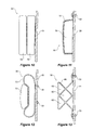
Figures 4 through 13 are cross-sectional views through various, alternative embodiments of impact absorbing elements attachable to the infant carrier illustrated inFigures 1 through 3 ; -
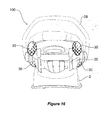
Figure 14 is a side view of an infant carrier according to a further exemplary embodiment; -
Figure 15 is a side view of the infant carrier inFigure 14 ; -
Figure 16 is an end view of the infant carrier illustrated inFigures 14 and15 , viewed from the head supporting end thereof; -
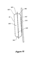
Figure 17 is a side view of an infant carrier according to a further exemplary embodiment; and -
Figure 18 is a sectional view through an impact absorbing module according to a further embodiment. - In the following description, like reference characters designate like or corresponding parts throughout the several views of the drawings.
- Referring now to
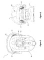
Figures 1 through 3 , where there is illustrated aninfant carrier 1 which is removably securable to a base 2 (seeFigure 3 ) via a releasable catch mechanism so as to form a child restraint for a vehicle. In use, thebase 2 is positioned upon a rear seat of the vehicle and is secured to the vehicle by means of a vehicle seat belt, preferably a combined lap/sash seat belt. - The
infant carrier 1 comprises ashell 20 of moulded plastic having an outerside, and an innerside lined with suitable padding andlining materials 22. The innerside of theinfant carrier 1 further comprises a five point harness 24 (seeFigure 2 ) for releasably securing an infant (or small child) 26 in theinfant carrier 1. - The
infant carrier 1 further comprises acarry handle 28 that can be rotated between a carry position (as illustrated inFigures 1 and3 ), and a stowed position (as illustrated inFigure 2 ) which positions thecarry handle 28 out of the way, so that an infant can be placed in and removed from theinfant carrier 1 without this being impeded by thecarry handle 28. - Depending from each of a pair of opposing sides of the outerside of the
infant carrier 1 at a head supporting end thereof is an outwardly directed (i.e. away from an innerside and any occupant)impact absorbing element 30 adapted to absorb and/or redirect or deflect blows incident to theinfant carrier 1 and thereby improve protection for at least the head of the child occupying theinfant carrier 1. In this exemplary embodiment, theimpact absorbing element 30 is a hollow, plastic blow moulded item that is secured to the outerside of theshell 20 of theinfant carrier 1 via plastic clips 33 (as perFigure 4 ) or tabs 34 (as perFigure 5 ). - The
thin shell 32 of theimpact absorbing elements 30 may be any one of hollow, partially or fully gas, liquid or gel filled, or contain or be filled with an energy absorbing material such as a foamed plastic or cellular material or the like. Further still, a combination of fillings may be employed. - The
thin shell 32 may be shaped so as to cause incident impact objects that may be flying about the vehicle in the case of an impact to be redirected or deflected away from theinfant carrier 1, reducing the likelihood that these objects will cause injury to the occupant of theinfant carrier 1. - Referring now to
Figure 6 , where it can be seen that in one form, theshell 32 of the or eachimpact absorbing element 30 may be shaped so as to incorporate features that aid in impact absorption or redirection. In this case,shell 32 incorporatesside walls 35 having the general shape of a sinusoidal wave form, whereupon at least some of the energy imparted by the collision of an incident object will cause theside walls 35 to be compressed with a 'concertina' affect. Moreover, there are alignedapertures impact absorbing element 30 andinfant carrier 20 respectively, so that some of any extant air in theshell 32 can be released in a controlled fashion as theimpact absorbing elements 30 are compressed by the incident impact. - Referring now to
Figure 7 , where it can be seen that in one form, theimpact absorbing elements 30 comprise athin shell 32 filled with amaterial 38 having an energy absorbing honeycomb structure. Referring now toFigure 8 , where it can be seen that in one form, theshell 32 of theimpact absorbing elements 30 may be formed from multiple (in this case 2)parts Figure 6 , there are aligned apertures in both onepart 52 of theelement shell 32 and theinfant carrier shell 20, so that some of any air in theshell 32 can be released in a controlled fashion as theelements 30 are compressed by the incident impact. Aseal 54 is retained betweenshell 30parts portions - With reference to
Figure 9 , where it is illustrated how it is that avalve 60 may be used to fill theaperture 37 in theshell 32. Such a valve may be used to seal theshell 32 or otherwise precisely control the release of fluid (particularly gas) or otherwise sacrificially rupture when theelement 30 is compressed by impact. - Referring now to
Figures 10 and 12 , where it can be seen that in one form, theimpact absorbing elements 30 may comprise multiple (in this case 2) energy absorbingcushion elements cushion elements - Referring now to
Figure 11 , where it can be seen that in one form, theimpact absorbing elements 30 comprise ashell 32 that extends over acushion element 70. In this way, theshell 32 may protect thecushion element 70 from damage, and thecushion element 70 may provide the majority of the impact energy absorption. - Referring now to
Figure 13 , where it can be seen that in one form, theimpact absorbing elements 30 are integrally formedenergy absorbing structures 80, defining, in this embodiment, a cross-section that is comprised of a plurality oftriangular apertures 82. In use, thestructure 80 is adapted to be crushed and thereby absorb incident impact energy. - By providing an
infant carrier 1 withimpact absorbing elements 30 located about the head support end of thecarrier 1 in particular, thecarrier 1 will provide improved protection for the infant, from both incidental bumps when thecarrier 1 is being carried, and major impacts that may result from motor vehicle accidents. - Referring now to
Figures 14 through 16 , where there is illustrated an infant carrier that is substantially the same asinfant carrier 1 discussed above, with the exception that there are six (three each side) externally directed (i.e. directed away from the occupant)impact absorbing elements 30 depending from thisinfant carrier 100. Two of theseimpact absorbing elements 30 are located about the periphery of the head supporting end of theinfant carrier 100, a further two are located about the periphery of the legs and feet supporting end of theinfant carrier 100, and the remaining two are located along the sides ofinfant carrier 100, between those at the head and feet supporting ends, this being about adjacent the position of an occupant's pelvis. - Referring now to
Figure 17 , where there is illustrated abase 200 of the type to which either ofinfant carriers base 100 comprises a pair of major opposingsides 102, where there is animpact absorbing element 30 secured to each of thesesides 102. - Referring now to
Figure 18 , where there is illustrated animpact absorbing element 30 comprised of two sheets of soft, pliableplastic material 300 secured together (such as by welding or use of adhesives) around matchingperimeters 302 thereof so as to create a casing for a piece of open cell (i.e. sponge-like) foam 304 (or any suitable material having similar properties). The casing is then secured to theexternal shell 20 of theinfant carrier impact absorbing element 30 some shape and volume, and the open cell structure contains gas that can be expelled when impacted upon, so as to slow down the rate of compression of theimpact absorbing element 30. This gas (air) may be released from the casing through one ormore apertures 306 formed insheets 300, or alternatively, by bursting a casing deficient ofsuch release apertures 306. - In an alternative, a closed cell foam may be used to vary the energy absorbing properties of the
impact absorbing element 30, as aside form its inherent properties, a closed cell foam may not contain as much gas for release when impacted upon. - In a further alternative, the foam element may be surrounded with additional air (i.e. the casing may be slightly pressurised), so as to provide a composite method for absorbing impact energy.
- It will be understood that the term "comprise" and any of its derivatives (e.g. comprises, comprising) as used in this specification is to be taken to be inclusive of features to which it refers, and is not meant to exclude the presence of any additional features unless otherwise stated or implied.
- The reference to any prior art in this specification is not, and should not be taken as, an acknowledgement of any form of suggestion that such prior art forms part of the common general knowledge.
- Although an illustrative embodiment of the present invention has been described in the foregoing detailed description, it will be understood that the invention is not limited to the embodiment disclosed, but is capable of numerous rearrangements, modifications and substitutions without departing from the scope of the invention as set forth and defined by the following claims.
Claims (19)
- A child restraint for a vehicle comprising a base, and an infant carrier securable to and separable from the base and the vehicle, and an impact energy absorbing element depending from an externally directed portion of the infant carrier.
- The child restraint of clam 1, wherein the externally directed impact energy absorbing element is positioned at or about at least an end thereof which is for supporting an occupant's head.
- The child restraint as in either of the preceding claims, wherein the infant carrier comprises a pair of side edges and a top edge at the head supporting end thereof, and an impact absorbing element is positioned on or along any one or more or all of these edges.
- The child restraint as in any one of the preceding claims, wherein an externally directed impact absorbing element extends right around a periphery of the infant carrier.
- The child restraint as in any one of claims 1 through 3, wherein a plurality of impact absorbing elements are positioned at a plurality of locations extending right around a periphery of the infant carrier.
- The child restraint as in any one of the preceding claims, wherein there is an impact absorbing element secured to an externally directed portion of the base.
- The child restraint as in any one of the preceding claims, wherein the or each impact absorbing element is adapted to absorb impact by means of any one or more of plastically or elastically deforming, cushioning, crushing, rupturing, deflating or bursting.
- The child restraint as in any one of the preceding claims, wherein the impact absorbing element comprises any one or more of a hollow and/or gas, liquid, gel or other energy absorbing material filled shell of deformable or cellular material.
- The child restraint of claim 8, wherein the shell has a thin wall of plastic material.
- The child restraint as in either of claims 8 or 9, wherein the shell may be either of rigid or soft and pliable, and may incorporate one or more apertures therein that facilitate the release of any fluids inside of the shell when this is subjected to an impact.
- The child restraint as in either of claims 8 or 9, wherein the shell bursts when subjected to an impact, said bursting permitting the release of fluids inside of the shell.
- The child restraint as in any one of claims 8 through 11, wherein the shell contains an element made of an open cell foam.
- The child restraint as in any one of claims 8 through 11, wherein the shell contains an element made of a closed cell foam.
- A child restraint for a vehicle comprising a base, and an infant carrier securable to and separable from the base and the vehicle, and an impact energy deflecting or redirecting element depending from an externally directed portion of the infant carrier.
- A child restraint for a vehicle comprising a base, an infant carrier securable to and separable from the base and the vehicle and comprising a shell having an outerside and an innerside, and an impact energy absorbing element depending from the outerside of the shell.
- The child restraint of claim 15, wherein the shell further comprises first and second ends and first and second sides, and an impact energy absorbing element depends from the outerside of one or more of the sides and/or ends.
- The child restraint of either of claims 15 or 16, wherein an impact energy absorbing element depends from the outerside of one or more of the sides at or about an end which is for supporting an occupant's head, and/or from said end.
- The child restraint of either of claims 15 or 16, wherein the or each impact energy absorbing element is outwardly directed with respect to the infant carrier.
- A child restraint for a vehicle being substantially as described in the specification with reference to and as illustrated in the accompanying representations.
Applications Claiming Priority (1)
| Application Number | Priority Date | Filing Date | Title |
|---|---|---|---|
| AU2010900684A AU2010900684A0 (en) | 2010-02-18 | Improvements relating to vehicle child restraints |
Publications (3)
| Publication Number | Publication Date |
|---|---|
| EP2368752A2 true EP2368752A2 (en) | 2011-09-28 |
| EP2368752A3 EP2368752A3 (en) | 2014-04-02 |
| EP2368752B1 EP2368752B1 (en) | 2017-10-18 |
Family
ID=44247908
Family Applications (1)
| Application Number | Title | Priority Date | Filing Date |
|---|---|---|---|
| EP11001348.9A Active EP2368752B1 (en) | 2010-02-18 | 2011-02-18 | Improvements relating to vehicle child restraints |
Country Status (3)
| Country | Link |
|---|---|
| EP (1) | EP2368752B1 (en) |
| AU (1) | AU2011200689A1 (en) |
| ES (1) | ES2655693T3 (en) |
Cited By (10)
| Publication number | Priority date | Publication date | Assignee | Title |
|---|---|---|---|---|
| EP2679439B1 (en) | 2012-06-25 | 2016-06-15 | Dorel France | Energy-dissipation system |
| CN107826005A (en) * | 2017-12-08 | 2018-03-23 | 清华大学苏州汽车研究院(相城) | A kind of lateral side protection and child safety seat for child safety seat |
| CN110966423A (en) * | 2018-10-01 | 2020-04-07 | 大陆泰密克微电子有限责任公司 | Pneumatic valve |
| USRE47971E1 (en) | 2012-06-01 | 2020-05-05 | Dorel Juvenile Group, Inc. | Energy-dissipation system |
| WO2021055337A1 (en) * | 2019-09-16 | 2021-03-25 | Monahan Products, LLC | Child carrier with side impact protection |
| EP3495196B1 (en) * | 2017-12-07 | 2022-05-11 | Bambino Prezioso Switzerland AG | Child car safety seat |
| EP4011691A1 (en) * | 2020-12-14 | 2022-06-15 | George TFE SCP | Child safety seat |
| US11511656B2 (en) | 2021-03-24 | 2022-11-29 | Monahan Products, LLC | Child restraint system with side impact bumper |
| US20230001832A1 (en) * | 2021-06-25 | 2023-01-05 | Dorel Juvenile Group, Inc. | Child restraint |
| US20230008534A1 (en) * | 2016-12-23 | 2023-01-12 | Britax Childcare Pty Ltd. | Child safety seat with energy absorbing elements |
Families Citing this family (2)
| Publication number | Priority date | Publication date | Assignee | Title |
|---|---|---|---|---|
| US10857968B2 (en) | 2017-12-07 | 2020-12-08 | Bambino Prezioso Switzerland Ag | Lateral shock absorber and child car safety seat therewith |
| DE202017107887U1 (en) * | 2017-12-22 | 2018-01-12 | Cybex Gmbh | Child seat for attachment to a motor vehicle seat |
Family Cites Families (4)
| Publication number | Priority date | Publication date | Assignee | Title |
|---|---|---|---|---|
| JP2000142194A (en) * | 1998-01-27 | 2000-05-23 | Aprica Kassai Inc | Child care apparatus |
| EP1452406B1 (en) * | 2003-02-25 | 2006-07-19 | Takata Corporation | Child seat |
| US7717506B2 (en) * | 2007-12-12 | 2010-05-18 | Britax Child Safety, Inc. | Child restraint apparatus for vehicle |
| ES2426225T5 (en) * | 2009-07-14 | 2024-03-05 | Britax Roemer Kindersicherheit Gmbh | Child seat with side impact protection |
-
2011
- 2011-02-17 AU AU2011200689A patent/AU2011200689A1/en not_active Abandoned
- 2011-02-18 EP EP11001348.9A patent/EP2368752B1/en active Active
- 2011-02-18 ES ES11001348.9T patent/ES2655693T3/en active Active
Non-Patent Citations (1)
| Title |
|---|
| None |
Cited By (15)
| Publication number | Priority date | Publication date | Assignee | Title |
|---|---|---|---|---|
| USRE47971E1 (en) | 2012-06-01 | 2020-05-05 | Dorel Juvenile Group, Inc. | Energy-dissipation system |
| EP2679439B1 (en) | 2012-06-25 | 2016-06-15 | Dorel France | Energy-dissipation system |
| US11760238B2 (en) * | 2016-12-23 | 2023-09-19 | Britax Childcare Pty Ltd. | Child safety seat with energy absorbing elements |
| US20230008534A1 (en) * | 2016-12-23 | 2023-01-12 | Britax Childcare Pty Ltd. | Child safety seat with energy absorbing elements |
| EP3495196B1 (en) * | 2017-12-07 | 2022-05-11 | Bambino Prezioso Switzerland AG | Child car safety seat |
| CN107826005A (en) * | 2017-12-08 | 2018-03-23 | 清华大学苏州汽车研究院(相城) | A kind of lateral side protection and child safety seat for child safety seat |
| CN110966423B (en) * | 2018-10-01 | 2022-05-03 | 大陆泰密克微电子有限责任公司 | Pneumatic valve |
| US11635154B2 (en) | 2018-10-01 | 2023-04-25 | Conti Temic Microelectronic Gmbh | Pneumatic valve |
| CN110966423A (en) * | 2018-10-01 | 2020-04-07 | 大陆泰密克微电子有限责任公司 | Pneumatic valve |
| US11318867B2 (en) | 2019-09-16 | 2022-05-03 | Monahan Products, LLC | Child carrier with side impact protection |
| WO2021055337A1 (en) * | 2019-09-16 | 2021-03-25 | Monahan Products, LLC | Child carrier with side impact protection |
| EP4011691A1 (en) * | 2020-12-14 | 2022-06-15 | George TFE SCP | Child safety seat |
| WO2022130159A1 (en) | 2020-12-14 | 2022-06-23 | George Tfe Scp | Child safety seat |
| US11511656B2 (en) | 2021-03-24 | 2022-11-29 | Monahan Products, LLC | Child restraint system with side impact bumper |
| US20230001832A1 (en) * | 2021-06-25 | 2023-01-05 | Dorel Juvenile Group, Inc. | Child restraint |
Also Published As
| Publication number | Publication date |
|---|---|
| AU2011200689A1 (en) | 2011-09-01 |
| EP2368752B1 (en) | 2017-10-18 |
| EP2368752A3 (en) | 2014-04-02 |
| ES2655693T3 (en) | 2018-02-21 |
Similar Documents
| Publication | Publication Date | Title |
|---|---|---|
| EP2368752B1 (en) | Improvements relating to vehicle child restraints | |
| EP2499020B1 (en) | Child seat with impact protection | |
| KR101318548B1 (en) | Child restraint apparatus for vehicle | |
| US10118510B2 (en) | Impact protection for child car seat | |
| CN109476270B (en) | Rear seat airbag module | |
| US4579385A (en) | Sunshade and protective device | |
| KR102171930B1 (en) | Air Bag Module | |
| US8505965B2 (en) | Vehicle occupant safety system with energy-absorbing elements, and method of operating same | |
| US7850234B2 (en) | Energy-dissipation system | |
| US6736455B1 (en) | Dual air bag and crossbar child safety seat | |
| US10358108B2 (en) | Adaptive, deployable restraint element for a vehicle safety system, airbag module, and vehicle safety system having a restraint element of this type, and use of the fin ray effect in an adaptive restraint element | |
| EP2969661B1 (en) | Airbag with deflector | |
| AU2018229548A1 (en) | Child seat with impact protection | |
| US8485580B2 (en) | Apparatus for protecting a child's head | |
| AU2013248252B2 (en) | Restraint cushioning improvements | |
| ES2308030T3 (en) | SEAT FOR VEHICLE WITH A PELVIS ENERGY ADMINISTRATION DEVICE. | |
| AU2014256427A1 (en) | Improvements relating to vehicle child restraints | |
| WO1995005954A1 (en) | Arrangement for head support | |
| JP2009531209A (en) | Vehicle occupant support | |
| KR20080112001A (en) | Passenger air bag system of vehicle |
Legal Events
| Date | Code | Title | Description |
|---|---|---|---|
| PUAI | Public reference made under article 153(3) epc to a published international application that has entered the european phase |
Free format text: ORIGINAL CODE: 0009012 |
|
| AK | Designated contracting states |
Kind code of ref document: A2 Designated state(s): AL AT BE BG CH CY CZ DE DK EE ES FI FR GB GR HR HU IE IS IT LI LT LU LV MC MK MT NL NO PL PT RO RS SE SI SK SM TR |
|
| AX | Request for extension of the european patent |
Extension state: BA ME |
|
| PUAL | Search report despatched |
Free format text: ORIGINAL CODE: 0009013 |
|
| AK | Designated contracting states |
Kind code of ref document: A3 Designated state(s): AL AT BE BG CH CY CZ DE DK EE ES FI FR GB GR HR HU IE IS IT LI LT LU LV MC MK MT NL NO PL PT RO RS SE SI SK SM TR |
|
| AX | Request for extension of the european patent |
Extension state: BA ME |
|
| RIC1 | Information provided on ipc code assigned before grant |
Ipc: B60N 2/427 20060101ALI20140227BHEP Ipc: B60N 2/28 20060101AFI20140227BHEP Ipc: B60N 2/42 20060101ALI20140227BHEP |
|
| 17P | Request for examination filed |
Effective date: 20140926 |
|
| RBV | Designated contracting states (corrected) |
Designated state(s): AL AT BE BG CH CY CZ DE DK EE ES FI FR GB GR HR HU IE IS IT LI LT LU LV MC MK MT NL NO PL PT RO RS SE SI SK SM TR |
|
| GRAP | Despatch of communication of intention to grant a patent |
Free format text: ORIGINAL CODE: EPIDOSNIGR1 |
|
| INTG | Intention to grant announced |
Effective date: 20170519 |
|
| GRAS | Grant fee paid |
Free format text: ORIGINAL CODE: EPIDOSNIGR3 |
|
| GRAA | (expected) grant |
Free format text: ORIGINAL CODE: 0009210 |
|
| AK | Designated contracting states |
Kind code of ref document: B1 Designated state(s): AL AT BE BG CH CY CZ DE DK EE ES FI FR GB GR HR HU IE IS IT LI LT LU LV MC MK MT NL NO PL PT RO RS SE SI SK SM TR |
|
| REG | Reference to a national code |
Ref country code: GB Ref legal event code: FG4D |
|
| REG | Reference to a national code |
Ref country code: CH Ref legal event code: EP |
|
| REG | Reference to a national code |
Ref country code: AT Ref legal event code: REF Ref document number: 937619 Country of ref document: AT Kind code of ref document: T Effective date: 20171115 Ref country code: IE Ref legal event code: FG4D |
|
| REG | Reference to a national code |
Ref country code: DE Ref legal event code: R096 Ref document number: 602011042439 Country of ref document: DE |
|
| REG | Reference to a national code |
Ref country code: SE Ref legal event code: TRGR |
|
| REG | Reference to a national code |
Ref country code: ES Ref legal event code: FG2A Ref document number: 2655693 Country of ref document: ES Kind code of ref document: T3 Effective date: 20180221 Ref country code: NL Ref legal event code: MP Effective date: 20171018 |
|
| REG | Reference to a national code |
Ref country code: FR Ref legal event code: PLFP Year of fee payment: 8 |
|
| REG | Reference to a national code |
Ref country code: LT Ref legal event code: MG4D |
|
| REG | Reference to a national code |
Ref country code: AT Ref legal event code: MK05 Ref document number: 937619 Country of ref document: AT Kind code of ref document: T Effective date: 20171018 |
|
| PG25 | Lapsed in a contracting state [announced via postgrant information from national office to epo] |
Ref country code: NL Free format text: LAPSE BECAUSE OF FAILURE TO SUBMIT A TRANSLATION OF THE DESCRIPTION OR TO PAY THE FEE WITHIN THE PRESCRIBED TIME-LIMIT Effective date: 20171018 |
|
| PG25 | Lapsed in a contracting state [announced via postgrant information from national office to epo] |
Ref country code: LT Free format text: LAPSE BECAUSE OF FAILURE TO SUBMIT A TRANSLATION OF THE DESCRIPTION OR TO PAY THE FEE WITHIN THE PRESCRIBED TIME-LIMIT Effective date: 20171018 Ref country code: FI Free format text: LAPSE BECAUSE OF FAILURE TO SUBMIT A TRANSLATION OF THE DESCRIPTION OR TO PAY THE FEE WITHIN THE PRESCRIBED TIME-LIMIT Effective date: 20171018 Ref country code: NO Free format text: LAPSE BECAUSE OF FAILURE TO SUBMIT A TRANSLATION OF THE DESCRIPTION OR TO PAY THE FEE WITHIN THE PRESCRIBED TIME-LIMIT Effective date: 20180118 |
|
| PG25 | Lapsed in a contracting state [announced via postgrant information from national office to epo] |
Ref country code: IS Free format text: LAPSE BECAUSE OF FAILURE TO SUBMIT A TRANSLATION OF THE DESCRIPTION OR TO PAY THE FEE WITHIN THE PRESCRIBED TIME-LIMIT Effective date: 20180218 Ref country code: LV Free format text: LAPSE BECAUSE OF FAILURE TO SUBMIT A TRANSLATION OF THE DESCRIPTION OR TO PAY THE FEE WITHIN THE PRESCRIBED TIME-LIMIT Effective date: 20171018 Ref country code: GR Free format text: LAPSE BECAUSE OF FAILURE TO SUBMIT A TRANSLATION OF THE DESCRIPTION OR TO PAY THE FEE WITHIN THE PRESCRIBED TIME-LIMIT Effective date: 20180119 Ref country code: RS Free format text: LAPSE BECAUSE OF FAILURE TO SUBMIT A TRANSLATION OF THE DESCRIPTION OR TO PAY THE FEE WITHIN THE PRESCRIBED TIME-LIMIT Effective date: 20171018 Ref country code: BG Free format text: LAPSE BECAUSE OF FAILURE TO SUBMIT A TRANSLATION OF THE DESCRIPTION OR TO PAY THE FEE WITHIN THE PRESCRIBED TIME-LIMIT Effective date: 20180118 Ref country code: AT Free format text: LAPSE BECAUSE OF FAILURE TO SUBMIT A TRANSLATION OF THE DESCRIPTION OR TO PAY THE FEE WITHIN THE PRESCRIBED TIME-LIMIT Effective date: 20171018 Ref country code: HR Free format text: LAPSE BECAUSE OF FAILURE TO SUBMIT A TRANSLATION OF THE DESCRIPTION OR TO PAY THE FEE WITHIN THE PRESCRIBED TIME-LIMIT Effective date: 20171018 |
|
| REG | Reference to a national code |
Ref country code: DE Ref legal event code: R097 Ref document number: 602011042439 Country of ref document: DE |
|
| PG25 | Lapsed in a contracting state [announced via postgrant information from national office to epo] |
Ref country code: EE Free format text: LAPSE BECAUSE OF FAILURE TO SUBMIT A TRANSLATION OF THE DESCRIPTION OR TO PAY THE FEE WITHIN THE PRESCRIBED TIME-LIMIT Effective date: 20171018 Ref country code: SK Free format text: LAPSE BECAUSE OF FAILURE TO SUBMIT A TRANSLATION OF THE DESCRIPTION OR TO PAY THE FEE WITHIN THE PRESCRIBED TIME-LIMIT Effective date: 20171018 Ref country code: CZ Free format text: LAPSE BECAUSE OF FAILURE TO SUBMIT A TRANSLATION OF THE DESCRIPTION OR TO PAY THE FEE WITHIN THE PRESCRIBED TIME-LIMIT Effective date: 20171018 Ref country code: DK Free format text: LAPSE BECAUSE OF FAILURE TO SUBMIT A TRANSLATION OF THE DESCRIPTION OR TO PAY THE FEE WITHIN THE PRESCRIBED TIME-LIMIT Effective date: 20171018 |
|
| PLBE | No opposition filed within time limit |
Free format text: ORIGINAL CODE: 0009261 |
|
| STAA | Information on the status of an ep patent application or granted ep patent |
Free format text: STATUS: NO OPPOSITION FILED WITHIN TIME LIMIT |
|
| PG25 | Lapsed in a contracting state [announced via postgrant information from national office to epo] |
Ref country code: PL Free format text: LAPSE BECAUSE OF FAILURE TO SUBMIT A TRANSLATION OF THE DESCRIPTION OR TO PAY THE FEE WITHIN THE PRESCRIBED TIME-LIMIT Effective date: 20171018 Ref country code: SM Free format text: LAPSE BECAUSE OF FAILURE TO SUBMIT A TRANSLATION OF THE DESCRIPTION OR TO PAY THE FEE WITHIN THE PRESCRIBED TIME-LIMIT Effective date: 20171018 Ref country code: RO Free format text: LAPSE BECAUSE OF FAILURE TO SUBMIT A TRANSLATION OF THE DESCRIPTION OR TO PAY THE FEE WITHIN THE PRESCRIBED TIME-LIMIT Effective date: 20171018 Ref country code: IT Free format text: LAPSE BECAUSE OF FAILURE TO SUBMIT A TRANSLATION OF THE DESCRIPTION OR TO PAY THE FEE WITHIN THE PRESCRIBED TIME-LIMIT Effective date: 20171018 |
|
| REG | Reference to a national code |
Ref country code: CH Ref legal event code: PL |
|
| 26N | No opposition filed |
Effective date: 20180719 |
|
| PG25 | Lapsed in a contracting state [announced via postgrant information from national office to epo] |
Ref country code: MC Free format text: LAPSE BECAUSE OF FAILURE TO SUBMIT A TRANSLATION OF THE DESCRIPTION OR TO PAY THE FEE WITHIN THE PRESCRIBED TIME-LIMIT Effective date: 20171018 |
|
| REG | Reference to a national code |
Ref country code: IE Ref legal event code: MM4A |
|
| REG | Reference to a national code |
Ref country code: BE Ref legal event code: MM Effective date: 20180228 |
|
| PG25 | Lapsed in a contracting state [announced via postgrant information from national office to epo] |
Ref country code: LU Free format text: LAPSE BECAUSE OF NON-PAYMENT OF DUE FEES Effective date: 20180218 Ref country code: SI Free format text: LAPSE BECAUSE OF FAILURE TO SUBMIT A TRANSLATION OF THE DESCRIPTION OR TO PAY THE FEE WITHIN THE PRESCRIBED TIME-LIMIT Effective date: 20171018 Ref country code: CH Free format text: LAPSE BECAUSE OF NON-PAYMENT OF DUE FEES Effective date: 20180228 Ref country code: LI Free format text: LAPSE BECAUSE OF NON-PAYMENT OF DUE FEES Effective date: 20180228 |
|
| PG25 | Lapsed in a contracting state [announced via postgrant information from national office to epo] |
Ref country code: IE Free format text: LAPSE BECAUSE OF NON-PAYMENT OF DUE FEES Effective date: 20180218 |
|
| PG25 | Lapsed in a contracting state [announced via postgrant information from national office to epo] |
Ref country code: BE Free format text: LAPSE BECAUSE OF NON-PAYMENT OF DUE FEES Effective date: 20180228 |
|
| PG25 | Lapsed in a contracting state [announced via postgrant information from national office to epo] |
Ref country code: MT Free format text: LAPSE BECAUSE OF NON-PAYMENT OF DUE FEES Effective date: 20180218 |
|
| PG25 | Lapsed in a contracting state [announced via postgrant information from national office to epo] |
Ref country code: HU Free format text: LAPSE BECAUSE OF FAILURE TO SUBMIT A TRANSLATION OF THE DESCRIPTION OR TO PAY THE FEE WITHIN THE PRESCRIBED TIME-LIMIT; INVALID AB INITIO Effective date: 20110218 Ref country code: PT Free format text: LAPSE BECAUSE OF FAILURE TO SUBMIT A TRANSLATION OF THE DESCRIPTION OR TO PAY THE FEE WITHIN THE PRESCRIBED TIME-LIMIT Effective date: 20171018 |
|
| PG25 | Lapsed in a contracting state [announced via postgrant information from national office to epo] |
Ref country code: MK Free format text: LAPSE BECAUSE OF NON-PAYMENT OF DUE FEES Effective date: 20171018 Ref country code: CY Free format text: LAPSE BECAUSE OF FAILURE TO SUBMIT A TRANSLATION OF THE DESCRIPTION OR TO PAY THE FEE WITHIN THE PRESCRIBED TIME-LIMIT Effective date: 20171018 |
|
| PG25 | Lapsed in a contracting state [announced via postgrant information from national office to epo] |
Ref country code: AL Free format text: LAPSE BECAUSE OF FAILURE TO SUBMIT A TRANSLATION OF THE DESCRIPTION OR TO PAY THE FEE WITHIN THE PRESCRIBED TIME-LIMIT Effective date: 20171018 |
|
| PGFP | Annual fee paid to national office [announced via postgrant information from national office to epo] |
Ref country code: FR Payment date: 20230217 Year of fee payment: 13 Ref country code: ES Payment date: 20230317 Year of fee payment: 13 |
|
| PGFP | Annual fee paid to national office [announced via postgrant information from national office to epo] |
Ref country code: TR Payment date: 20230215 Year of fee payment: 13 Ref country code: SE Payment date: 20230220 Year of fee payment: 13 Ref country code: GB Payment date: 20230221 Year of fee payment: 13 Ref country code: DE Payment date: 20230216 Year of fee payment: 13 |