EP2368736A1 - Open roof construction for a vehicle - Google Patents
Open roof construction for a vehicle Download PDFInfo
- Publication number
- EP2368736A1 EP2368736A1 EP11159258A EP11159258A EP2368736A1 EP 2368736 A1 EP2368736 A1 EP 2368736A1 EP 11159258 A EP11159258 A EP 11159258A EP 11159258 A EP11159258 A EP 11159258A EP 2368736 A1 EP2368736 A1 EP 2368736A1
- Authority
- EP
- European Patent Office
- Prior art keywords
- movable panel
- opening
- guide
- adjustment screws
- roof construction
- Prior art date
- Legal status (The legal status is an assumption and is not a legal conclusion. Google has not performed a legal analysis and makes no representation as to the accuracy of the status listed.)
- Granted
Links
- 238000010276 construction Methods 0.000 title claims abstract description 26
- 239000011521 glass Substances 0.000 claims description 4
- 239000000463 material Substances 0.000 claims description 4
- 230000007246 mechanism Effects 0.000 description 4
- 238000000034 method Methods 0.000 description 2
- 230000006378 damage Effects 0.000 description 1
Images


Classifications
-
- B—PERFORMING OPERATIONS; TRANSPORTING
- B60—VEHICLES IN GENERAL
- B60J—WINDOWS, WINDSCREENS, NON-FIXED ROOFS, DOORS, OR SIMILAR DEVICES FOR VEHICLES; REMOVABLE EXTERNAL PROTECTIVE COVERINGS SPECIALLY ADAPTED FOR VEHICLES
- B60J7/00—Non-fixed roofs; Roofs with movable panels, e.g. rotary sunroofs
- B60J7/02—Non-fixed roofs; Roofs with movable panels, e.g. rotary sunroofs of sliding type, e.g. comprising guide shoes
Definitions
- the invention relates to an open roof construction for a vehicle, comprising a stationary roof, a roof opening provided therein, a movable panel for opening and closing said roof opening and two stationary guides positioned along opposite longitudinal edges of the roof opening for guiding two guide shoes provided close to the forward edge of the movable panel, which guides each comprise at least a vertically extending guide part for a guiding cooperation with a corresponding vertically extending guide shoe part, wherein the guide shoes are attached to the movable panel in a substantially vertically and horizontally adjustable manner by means of substantially transversally extending adjustment screws.
- indications as 'vertically', 'horizontally' and 'transversally' in a conventional manner refer to the geometry of the vehicle (such that, for example, the transverse direction extends in a horizontal plane across the vehicle).
- the adjustment screws allow positioning the movable panel correctly with respect to the stationary roof, especially in the closed position of the movable panel.
- the adjustment screws are loosened and the position of the guide shoes relative to the movable panel (and thus the position of the movable panel relative to the stationary roof) is adjusted until the movable panel is positioned in a correct manner (which may mean, for example, correctly engaging seals surrounding the roof opening).
- the adjustment screws are tightened again for fixating the obtained position of the guide shoes relative to the movable panel.
- the adjustment screws have to be accessible in said according to the state of the art this means that in the closed position of the movable panel the adjustment screws are located above the stationary guides, as seen in a transverse direction. This, however, results in such a distance between the guide shoes and the movable panel that in the closed position of the panel the guide shoes (and the corresponding end parts of the stationary guides, the 'locators') protrude rather far downwardly towards the passenger compartment of the vehicle, requiring, on one hand, a low position of the lower lining of the roof of the vehicle and creating, on the other hand, a substantial risk on injuries during accidents.
- an open roof construction of the type referred to above which is characterized in that in a position of the movable panel fully closing the roof opening the adjustment screws are covered by the stationary guides as seen in a transverse direction and wherein the vertically extending guide parts of the stationary guides are provided with openings for, in said position, allowing access to the adjustment screws by means of an appropriate tool.
- the expression 'covered by the stationary guides' means that the adjustment screws are located within the outline of the stationary guides as seen in a transverse (horizontal) direction, behind the vertically extending guide part.
- the guide shoes may be positioned closer to the movable panel. In the closed position of the movable panel this leads to less protrusion of the guide shoes and the corresponding locators of the stationary guides into the passenger compartment of the vehicle while still allowing an adjustment of the movable panel.
- the dimensions of the opening are smaller than the dimensions of the vertically extending guide shoe part. This effectively prevents the guide shoe from entering the opening with a resulting jamming of the guide shoe in the guide.
- said guide shoe part has a horizontal dimension and a vertical dimension wherein the opening has a horizontal dimension and a vertical dimension, wherein the horizontal dimension of the opening is smaller than the horizontal dimension of said guide shoe part and wherein the vertical dimension of the opening is equal to or smaller than the vertical dimension of said guide shoe part.
- the adjustment screws engage the guide shoes while extending through holes in brackets which are attached to the movable panel.
- the adjustment screws may engage the guide shoes directly, it is also conceivable that such an engagement occurs indirectly through braces connected to and carrying the guide shoes.
- the adjust" merit screws have a fixed position relative to the guide shoes and may be adjusted relative to the movable panel. As a result, the position of the adjustment screws relative to the openings in the stationary guides does not change during adjusting the position of the movable panel, allowing the use of rather small holes.
- the holes in the brackets have an oversized shape (relative to the shafts of the screws).
- the shafts of the loosened adjustment screws may slide in said elongated holes in a vertical and/or horizontal direction to the desired position in which the screws are tightened and the screw heads engage the bracket.
- the adjustment screws can be passed through the holes in the brackets and attached to the guide shoes (or braces connected thereto) in an open position of the movable panel.
- the panel can be moved to its closed position in which the adjustment screws are accessible through the openings in the stationary guides and will be operated (loosened and tightened) for adjusting the position of the movable panel by sliding the adjustment screws to a new position in said holes.
- the holes in the brackets have an open connection to the surroundings. This feature allows a simplification of assembling the open roof construction through a reduction of steps required therefore.
- the adjustment screws may be attached to the guide shoes first, after which the guide shoes are positioned in the stationary guides according to the closed position of the movable panel (thus, positioned in the locators). In this position the movable panel with its brackets is mounted to the guide shoes by sliding the open connection of the holes over the shafts of the screws until the shafts reach the holes and the movable panel reaches its correct closed position. Finally the adjustment screws are tightened.
- the movable panel for its major part is made of glass or a corresponding material.
- the provision of the measures according to the invention is advantageous because other adjustment mechanisms directly acting on the movable panel itself are not preferred because cracks or fractures could occur in the glass material.
- a vehicle comprising an open roof construction.
- Said open roof construction basically comprises a stationary roof 1 in which a roof opening 2 is defined.
- a movable panel 3 for opening and closing said roof opening 2 is provided having two guide shoes 4 provided close to the forward edge 5 of the movable panel.
- Said guide shoes 4 cooperate with two stationary guides 6 positioned along opposite longitudinal edges 7 of the roof opening.
- the movable panel 3 for its major part may be made of glass or a corresponding material.
- the guide shoes 4 are attached to the movable panel 3 in a substantially vertically and horizontally adjustable manner by means of substantially transversally extending adjustment screws (to be elucidated later), such that in its closed position the panel 3 may be adjusted to achieve a correct position (e.g. cooperating properly with seals -not illustrated- surrounding the roof opening 2).
- the guide shoes 4 are attached to braces 8 which by means of adjustment screws 9 are connected to brackets 10 which are part of the movable panel 3.
- the guides comprise a guide channel 17 for a guide shoe 4 with a vertically extending guide part 18 for a guiding cooperation with a corresponding vertically extending guide shoe part (visible in figure 2 as the frontal part of guide shoe 4).
- a tool for example screw driver 11 in figure 3
- the adjustment screws 9 are located above the stationary guide 6 (especially the guide channel 17 thereof) in this closed position.
- the adjustment screws 9 are covered by the vertically extending part 18 of the stationary guides 6 as seen in a transverse direction and said vertically extending parts 18 of the stationary guides 6 are provided with openings 13 for allowing access to the adjustment screws 9 in said position by means of an appropriate tool 11 ( figure 6 ).
- the guide shoes 4 may be positioned closer to the panel 3, as applies too for the guides 6 and the locators 12, such that it is possible to position the corresponding part of the stationary roof 1 (which may be a lining) at a higher level.
- the panel 3 will reach an open position (as illustrated by figures 5 and 7 ) which is equal to the open position which will be reached by the state of the art open roof construction according to figures 2 and 3 , however with less height required for the mechanism between the panel 3 and the stationary roof (lining) 1. It is noted that the distance between the lining 1 and locators 12 has been exaggerated in figures 4 and 5 and normally will be as small as indicated in figure 2 .
- the stationary guides 6 are constructed from the original state of the art guides 6 as shown in figure 3 , however with an opening in vertically extending guide part 18.
- the bracket comprises openings 16 for accommodating the adjustment screws (not illustrated) having an oversized shape with an open connection 14 to the surroundings.
- the adjustment screws 9 may be attached to the braces 8 of the guide shoes 4 first (for example in the screw holes 15 illustrated), after which the guide shoes 4 are positioned in the guides 6 according to the closed position of the movable panel 3 (thus, positioned in the locators 12).
- the dimensions of the opening 13 generally will be smaller than the dimensions of the corresponding vertically extending part of the guide shoe 4.
- said part of the guide shoe 14 has a horizontal dimension and a vertical dimension and the opening 13 has a horizontal dimension and a vertical dimension. It is clearly visible that the horizontal dimension of the opening 13 is smaller than the horizontal dimension of said part of the guide shoe 4 and that the vertical dimension of the opening 13 substantially is equal to the vertical dimension of said guide shoe part.
Abstract
Description
- The invention relates to an open roof construction for a vehicle, comprising a stationary roof, a roof opening provided therein, a movable panel for opening and closing said roof opening and two stationary guides positioned along opposite longitudinal edges of the roof opening for guiding two guide shoes provided close to the forward edge of the movable panel, which guides each comprise at least a vertically extending guide part for a guiding cooperation with a corresponding vertically extending guide shoe part, wherein the guide shoes are attached to the movable panel in a substantially vertically and horizontally adjustable manner by means of substantially transversally extending adjustment screws.
- Before discussing the state of the art it is noted that indications as 'vertically', 'horizontally' and 'transversally' in a conventional manner refer to the geometry of the vehicle (such that, for example, the transverse direction extends in a horizontal plane across the vehicle).
- The adjustment screws allow positioning the movable panel correctly with respect to the stationary roof, especially in the closed position of the movable panel. In such a closed position the adjustment screws are loosened and the position of the guide shoes relative to the movable panel (and thus the position of the movable panel relative to the stationary roof) is adjusted until the movable panel is positioned in a correct manner (which may mean, for example, correctly engaging seals surrounding the roof opening). Next the adjustment screws are tightened again for fixating the obtained position of the guide shoes relative to the movable panel. As a result it is assured that during following opening and closing procedures the movable panel always will reach the correct closed position.
- Because the adjustment of the position of the guide shoes is carried out in the closed position of the movable panel, the adjustment screws have to be accessible in said according to the state of the art this means that in the closed position of the movable panel the adjustment screws are located above the stationary guides, as seen in a transverse direction. This, however, results in such a distance between the guide shoes and the movable panel that in the closed position of the panel the guide shoes (and the corresponding end parts of the stationary guides, the 'locators') protrude rather far downwardly towards the passenger compartment of the vehicle, requiring, on one hand, a low position of the lower lining of the roof of the vehicle and creating, on the other hand, a substantial risk on injuries during accidents.
- It is an object of the present invention to provide an improved open roof construction of the type referred to above.
- Thus, in accordance with the present invention an open roof construction of the type referred to above is provided which is characterized in that in a position of the movable panel fully closing the roof opening the adjustment screws are covered by the stationary guides as seen in a transverse direction and wherein the vertically extending guide parts of the stationary guides are provided with openings for, in said position, allowing access to the adjustment screws by means of an appropriate tool.
- The expression 'covered by the stationary guides' means that the adjustment screws are located within the outline of the stationary guides as seen in a transverse (horizontal) direction, behind the vertically extending guide part. As a result of such a disposition the guide shoes may be positioned closer to the movable panel. In the closed position of the movable panel this leads to less protrusion of the guide shoes and the corresponding locators of the stationary guides into the passenger compartment of the vehicle while still allowing an adjustment of the movable panel.
- In a preferred embodiment the dimensions of the opening are smaller than the dimensions of the vertically extending guide shoe part. This effectively prevents the guide shoe from entering the opening with a resulting jamming of the guide shoe in the guide.
- More preferably, then, said guide shoe part has a horizontal dimension and a vertical dimension wherein the opening has a horizontal dimension and a vertical dimension, wherein the horizontal dimension of the opening is smaller than the horizontal dimension of said guide shoe part and wherein the vertical dimension of the opening is equal to or smaller than the vertical dimension of said guide shoe part.
- In another preferred embodiment of the open roof construction according to the present invention the adjustment screws engage the guide shoes while extending through holes in brackets which are attached to the movable panel.
- Although the adjustment screws may engage the guide shoes directly, it is also conceivable that such an engagement occurs indirectly through braces connected to and carrying the guide shoes. However, in either way the adjust" merit screws have a fixed position relative to the guide shoes and may be adjusted relative to the movable panel. As a result, the position of the adjustment screws relative to the openings in the stationary guides does not change during adjusting the position of the movable panel, allowing the use of rather small holes.
- For allowing such an adjustment of the position of the movable panel, in one embodiment of the open roof construction according to the present invention the holes in the brackets have an oversized shape (relative to the shafts of the screws). The shafts of the loosened adjustment screws may slide in said elongated holes in a vertical and/or horizontal direction to the desired position in which the screws are tightened and the screw heads engage the bracket. During a process of assembling the open roof construction the adjustment screws can be passed through the holes in the brackets and attached to the guide shoes (or braces connected thereto) in an open position of the movable panel. Next the panel can be moved to its closed position in which the adjustment screws are accessible through the openings in the stationary guides and will be operated (loosened and tightened) for adjusting the position of the movable panel by sliding the adjustment screws to a new position in said holes.
- In another embodiment of the open roof construction according to present invention the holes in the brackets have an open connection to the surroundings. This feature allows a simplification of assembling the open roof construction through a reduction of steps required therefore. The adjustment screws may be attached to the guide shoes first, after which the guide shoes are positioned in the stationary guides according to the closed position of the movable panel (thus, positioned in the locators). In this position the movable panel with its brackets is mounted to the guide shoes by sliding the open connection of the holes over the shafts of the screws until the shafts reach the holes and the movable panel reaches its correct closed position. Finally the adjustment screws are tightened.
- It is possible that the movable panel for its major part is made of glass or a corresponding material. Especially in such a case the provision of the measures according to the invention is advantageous because other adjustment mechanisms directly acting on the movable panel itself are not preferred because cracks or fractures could occur in the glass material.
- Hereinafter the invention will be elucidated while referring to the drawings in which:
-
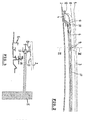
Figure 1 schematically shows a vehicle provided with an open roof construction; -
Figure 2 shows a longitudinal section of a state of the art open roof construction: -
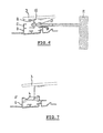
Figure 3 shows a cross section according to III-III infigure 2 with applied tool; -
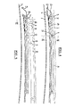
Figure 4 shows a longitudinal section of an open roof construction according to the invention in a closed position; -
Figure 5 shows a longitudinal section of the same open roof construction according to the invention in an open position; -
Figure 6 shows a cross section according to VI-VI infigure 4 with applied tool; -
Figure 7 shows a cross section according to VII-VII infigure 5 , and -
Figure 8 shows a perspective view of part of another embodiment of an open roof construction in accordance with the present invention. - Referring to
figure 1 a vehicle is shown comprising an open roof construction. Said open roof construction basically comprises astationary roof 1 in which aroof opening 2 is defined. Amovable panel 3 for opening and closing saidroof opening 2 is provided having two guide shoes 4 provided close to theforward edge 5 of the movable panel. Said guide shoes 4 cooperate with twostationary guides 6 positioned along opposite longitudinal edges 7 of the roof opening. - The
movable panel 3 for its major part may be made of glass or a corresponding material. - The manner in which the
panel 3 is moved between its opened and closed positions and mechanisms capable therefore are well known in the state of the art and thus do not need any detailed description here. It is noted only that the cooperation between the guide shoes 4 andstationary guides 6 may occur by means of operating mechanisms causing the desired movements of the panel (e.g. lifting and sliding). - The guide shoes 4 are attached to the
movable panel 3 in a substantially vertically and horizontally adjustable manner by means of substantially transversally extending adjustment screws (to be elucidated later), such that in its closed position thepanel 3 may be adjusted to achieve a correct position (e.g. cooperating properly with seals -not illustrated- surrounding the roof opening 2). - According to the state of the art, illustrated in
figures 2 and 3 , the guide shoes 4 are attached tobraces 8 which by means ofadjustment screws 9 are connected tobrackets 10 which are part of themovable panel 3. The guides comprise aguide channel 17 for a guide shoe 4 with a vertically extendingguide part 18 for a guiding cooperation with a corresponding vertically extending guide shoe part (visible infigure 2 as the frontal part of guide shoe 4). Because the adjustment screws have to be operated by a tool (forexample screw driver 11 infigure 3 ) in the closed position of the movable panel 3 (in which the forward guide shoes 4 are located in the most forward part of thestationary guides 6, the so-called locators 12) theadjustment screws 9 are located above the stationary guide 6 (especially theguide channel 17 thereof) in this closed position. - According to the present invention, however, in a position of the
movable panel 3 fully closing the roof opening as illustrated infigures 4 and6 , theadjustment screws 9 are covered by the vertically extendingpart 18 of thestationary guides 6 as seen in a transverse direction and said vertically extendingparts 18 of thestationary guides 6 are provided withopenings 13 for allowing access to theadjustment screws 9 in said position by means of an appropriate tool 11 (figure 6 ). As a result the guide shoes 4 may be positioned closer to thepanel 3, as applies too for theguides 6 and thelocators 12, such that it is possible to position the corresponding part of the stationary roof 1 (which may be a lining) at a higher level. - Because the geometry of the track defined by the
guides 6 does not change, thepanel 3 will reach an open position (as illustrated byfigures 5 and7 ) which is equal to the open position which will be reached by the state of the art open roof construction according tofigures 2 and 3 , however with less height required for the mechanism between thepanel 3 and the stationary roof (lining) 1. It is noted that the distance between thelining 1 andlocators 12 has been exaggerated infigures 4 and 5 and normally will be as small as indicated infigure 2 . - As illustrated clearly in
figures 6 and 7 , thestationary guides 6 are constructed from the original state of theart guides 6 as shown infigure 3 , however with an opening in vertically extendingguide part 18. - As shown in the embodiment according to
figure 8 in which abrace 8 with attached guide shoe 4 and part of a bracket 10 (connected to the panel -not shown-) are illustrated, the bracket comprisesopenings 16 for accommodating the adjustment screws (not illustrated) having an oversized shape with an open connection 14 to the surroundings. This feature allows a simplification of assembling the open roof construction through a reduction of steps required therefore. Theadjustment screws 9 may be attached to thebraces 8 of the guide shoes 4 first (for example in thescrew holes 15 illustrated), after which the guide shoes 4 are positioned in theguides 6 according to the closed position of the movable panel 3 (thus, positioned in the locators 12). In this position themovable panel 3 with itsbrackets 10 is mounted to the guide shoes 4 by sliding the open connection 14 of theholes 16 over the shafts of the screws until the shafts reach theholes 16 and the movable panel reaches its correct closed position. Finally the adjustment screws are tightened by passing atool 11 through theopenings 13 in the vertically extending parts of thestationary guides 6. - The dimensions of the
opening 13 generally will be smaller than the dimensions of the corresponding vertically extending part of the guide shoe 4. Specifically, referring for example tofigure 5 , said part of the guide shoe 14 has a horizontal dimension and a vertical dimension and theopening 13 has a horizontal dimension and a vertical dimension. It is clearly visible that the horizontal dimension of theopening 13 is smaller than the horizontal dimension of said part of the guide shoe 4 and that the vertical dimension of theopening 13 substantially is equal to the vertical dimension of said guide shoe part. - The invention is not limited to the embodiments described before which may be varied in many ways within the scope of the invention as defined by the appending claims.
Claims (7)
- Open roof construction for a vehicle, comprising a stationary roof, a roof opening provided therein, a movable panel for opening and closing said roof opening and two stationary guides positioned along opposite longitudinal edges of the roof opening for guiding two guide shoes provided close to the forward edge of the movable panel, which guides each comprise at least a vertically extending guide part for a guiding cooperation with a corresponding vertically extending guide shoe part, wherein the guide shoes are attached to the movable panel in a substantially vertically and horizontally adjustable manner by means of substantially transversally extending adjustment screws, characterized in that in a position of the movable panel fully closing the roof opening the adjustment screws are covered by the stationary guides as seen in a transverse direction and wherein the vertically extending guide parts of the stationary guides are provided with openings for, in said position, allowing access to the adjustment screws by means of an appropriate tool.
- Open roof construction according to claim 1, wherein the dimensions of the opening are smaller than the dimensions of the vertically extending guide shoe part.
- Open roof construction according to claim 2, wherein said guide shoe part has a horizontal dimension and a vertical dimension and wherein the opening has a horizontal dimension and a vertical dimension, wherein the horizontal dimension of the opening is smaller than the horizontal dimension of said guide shoe part and wherein the vertical dimension of the opening is equal to or smaller than the vertical dimension of said guide shoe part.
- Open roof construction according to any of the claims 1-3, wherein the adjustment screws engage the guide shoes while extending through holes in brackets which are attached to the movable panel.
- Open roof construction according to claim 4, wherein the holes in the brackets have an oversized shape.
- Open roof construction according to claim 4 or 5, wherein the holes in the brackets have an open connection to the surroundings.
- Open roof construction according to any of the previous claims, wherein the movable panel for its major part is made of glass or a corresponding material.
Priority Applications (1)
| Application Number | Priority Date | Filing Date | Title |
|---|---|---|---|
| EP11159258.0A EP2368736B1 (en) | 2010-03-23 | 2011-03-22 | Open roof construction for a vehicle |
Applications Claiming Priority (2)
| Application Number | Priority Date | Filing Date | Title |
|---|---|---|---|
| EP10157317A EP2368735A1 (en) | 2010-03-23 | 2010-03-23 | Open roof construction for a vehicle |
| EP11159258.0A EP2368736B1 (en) | 2010-03-23 | 2011-03-22 | Open roof construction for a vehicle |
Publications (2)
| Publication Number | Publication Date |
|---|---|
| EP2368736A1 true EP2368736A1 (en) | 2011-09-28 |
| EP2368736B1 EP2368736B1 (en) | 2014-12-31 |
Family
ID=42651096
Family Applications (2)
| Application Number | Title | Priority Date | Filing Date |
|---|---|---|---|
| EP10157317A Withdrawn EP2368735A1 (en) | 2010-03-23 | 2010-03-23 | Open roof construction for a vehicle |
| EP11159258.0A Active EP2368736B1 (en) | 2010-03-23 | 2011-03-22 | Open roof construction for a vehicle |
Family Applications Before (1)
| Application Number | Title | Priority Date | Filing Date |
|---|---|---|---|
| EP10157317A Withdrawn EP2368735A1 (en) | 2010-03-23 | 2010-03-23 | Open roof construction for a vehicle |
Country Status (3)
| Country | Link |
|---|---|
| US (1) | US8840174B2 (en) |
| EP (2) | EP2368735A1 (en) |
| CN (1) | CN102198788B (en) |
Families Citing this family (7)
| Publication number | Priority date | Publication date | Assignee | Title |
|---|---|---|---|---|
| EP2711219B1 (en) * | 2012-09-25 | 2015-07-22 | Inalfa Roof Systems Group B.V. | Drive mechanism and open roof construction provided therewith |
| EP2711218B1 (en) * | 2012-09-25 | 2015-07-22 | Inalfa Roof Systems Group B.V. | Drive mechanism and open roof construction provided therewith |
| DE102014104834A1 (en) * | 2014-04-04 | 2015-10-08 | Webasto SE | System for a vehicle roof |
| EP3085562B1 (en) * | 2015-04-20 | 2018-03-14 | Inalfa Roof Systems Group B.V. | Roof assembly for a vehicle |
| EP3608135B1 (en) * | 2018-08-09 | 2022-03-09 | Inalfa Roof Systems Group B.V. | Open roof construction for a vehicle and method of attaching a panel |
| US10532639B1 (en) * | 2018-09-06 | 2020-01-14 | AISIN Technical Center of America, Inc. | Holding assembly for a sunroof rail system |
| US10618387B2 (en) * | 2018-09-06 | 2020-04-14 | AISIN Technical Center of America, Inc. | Sunroof rail guide assembly |
Citations (5)
| Publication number | Priority date | Publication date | Assignee | Title |
|---|---|---|---|---|
| US3066975A (en) * | 1958-10-18 | 1962-12-04 | Baier Wilhelm Kg | Movable roof structures for automobiles or the like |
| JPS5868424U (en) * | 1981-10-31 | 1983-05-10 | ダイキヨ−・ベバスト株式会社 | Sliding roof mounting adjustment device |
| FR2516870A1 (en) * | 1981-11-26 | 1983-05-27 | Rockwell Golde Gmbh | SUNROOF FOR MOTOR VEHICLES |
| GB2165193A (en) * | 1984-09-28 | 1986-04-09 | Rockwell Golde Gmbh | Method of and apparatus for the height adjustment and installation of a sliding and/or raisable roof member to be fitted into an automobile |
| DE3510759A1 (en) * | 1985-03-25 | 1986-09-25 | Karosseriewerke Weinsberg Gmbh, 7102 Weinsberg | Height-adjustment device for vehicle roof covers which can at least be knocked out |
Family Cites Families (8)
| Publication number | Priority date | Publication date | Assignee | Title |
|---|---|---|---|---|
| JPS5868424A (en) | 1981-10-20 | 1983-04-23 | Nisshin Steel Co Ltd | Method and tool for preventing ear breakage of band steel coil |
| US4650243A (en) * | 1983-08-26 | 1987-03-17 | Sky-Top Sunroofs, Ltd. | Sliding and venting sunroof |
| DE3343900A1 (en) * | 1983-12-05 | 1985-06-13 | Karosseriewerke Weinsberg Gmbh, 7102 Weinsberg | Front-end support for motor vehicle roof covers which can be at least swivelled out |
| FR2619535B1 (en) * | 1987-08-20 | 1994-06-17 | Webasto Ag Fahrzeugtechnik | VEHICLE ROOF WITH A ROOF OPENING |
| US5026113A (en) * | 1988-09-09 | 1991-06-25 | Sky-Top Sunroofs Ltd. | Sliding and venting sunroof |
| DE20023526U1 (en) * | 1999-04-22 | 2004-08-26 | Inalfa Roof Systems Group B.V. | Open roof construction for vehicle, has link including two plate members at least at the location of the point of attachment between which the lip of the closure element is accommodated |
| NL1011859C2 (en) * | 1999-04-22 | 2000-10-24 | Inalfa Ind Bv | Open roof construction for a vehicle. |
| AT409067B (en) * | 2000-03-02 | 2002-05-27 | Blum Gmbh Julius | EXTENDING GUIDE FOR DRAWERS |
-
2010
- 2010-03-23 EP EP10157317A patent/EP2368735A1/en not_active Withdrawn
-
2011
- 2011-03-22 EP EP11159258.0A patent/EP2368736B1/en active Active
- 2011-03-23 CN CN201110071116.0A patent/CN102198788B/en active Active
- 2011-03-23 US US13/070,244 patent/US8840174B2/en active Active
Patent Citations (5)
| Publication number | Priority date | Publication date | Assignee | Title |
|---|---|---|---|---|
| US3066975A (en) * | 1958-10-18 | 1962-12-04 | Baier Wilhelm Kg | Movable roof structures for automobiles or the like |
| JPS5868424U (en) * | 1981-10-31 | 1983-05-10 | ダイキヨ−・ベバスト株式会社 | Sliding roof mounting adjustment device |
| FR2516870A1 (en) * | 1981-11-26 | 1983-05-27 | Rockwell Golde Gmbh | SUNROOF FOR MOTOR VEHICLES |
| GB2165193A (en) * | 1984-09-28 | 1986-04-09 | Rockwell Golde Gmbh | Method of and apparatus for the height adjustment and installation of a sliding and/or raisable roof member to be fitted into an automobile |
| DE3510759A1 (en) * | 1985-03-25 | 1986-09-25 | Karosseriewerke Weinsberg Gmbh, 7102 Weinsberg | Height-adjustment device for vehicle roof covers which can at least be knocked out |
Also Published As
| Publication number | Publication date |
|---|---|
| CN102198788A (en) | 2011-09-28 |
| US20110233971A1 (en) | 2011-09-29 |
| EP2368736B1 (en) | 2014-12-31 |
| EP2368735A1 (en) | 2011-09-28 |
| CN102198788B (en) | 2015-04-08 |
| US8840174B2 (en) | 2014-09-23 |
Similar Documents
| Publication | Publication Date | Title |
|---|---|---|
| EP2368736B1 (en) | Open roof construction for a vehicle | |
| US8567859B2 (en) | Sliding roof system, in particular for motor vehicles | |
| US9186966B2 (en) | Drive system for a movable roof part of a roof module of a motor vehicle | |
| US8523278B2 (en) | Sliding roof device, in particular for a motor vehicle | |
| US20180326822A1 (en) | Drive system for a movable roof part of a spoiler roof module of a motor vehicle | |
| EP1561619A2 (en) | Vehicle door with slidable window glass | |
| US20180326821A1 (en) | Drive system for a movable roof part of a spoiler roof module of a motor vehicle | |
| KR20150017739A (en) | Side panel of a cover on a vehicle roof | |
| EP2305500B1 (en) | Open roof construction for a vehicle | |
| US20070138841A1 (en) | Sliding roof system for a motor vehicle | |
| US20180326823A1 (en) | Drive system for a movable roof part of a spoiler roof module of a motor vehicle | |
| EP2711218B1 (en) | Drive mechanism and open roof construction provided therewith | |
| JP2009514727A (en) | The movable roof part of the openable vehicle roof | |
| US10399416B2 (en) | Sliding roof system for a motor vehicle | |
| EP3085562B1 (en) | Roof assembly for a vehicle | |
| EP2711219B1 (en) | Drive mechanism and open roof construction provided therewith | |
| EP1494883B1 (en) | Roof assembly for a vehicle | |
| WO2011006892A3 (en) | Roof assembly for a roof of a vehicle, and method of moving a closure panel and wind deflector of a roof assembly | |
| EP3661778B1 (en) | Open roof construction for a vehicle | |
| EP2501575B1 (en) | Tiltable sun roof for vehicles | |
| EP2853425B1 (en) | Roof apparatus | |
| EP1760235A1 (en) | Device for actuating the rear side windows of a convertible vehicle | |
| KR101864034B1 (en) | Assembly of sunroof | |
| EP3381750A1 (en) | Sunroof apparatus for vehicle | |
| JP2004090912A (en) | Vehicle roof having two roof openings |
Legal Events
| Date | Code | Title | Description |
|---|---|---|---|
| PUAI | Public reference made under article 153(3) epc to a published international application that has entered the european phase |
Free format text: ORIGINAL CODE: 0009012 |
|
| AK | Designated contracting states |
Kind code of ref document: A1 Designated state(s): AL AT BE BG CH CY CZ DE DK EE ES FI FR GB GR HR HU IE IS IT LI LT LU LV MC MK MT NL NO PL PT RO RS SE SI SK SM TR |
|
| AX | Request for extension of the european patent |
Extension state: BA ME |
|
| 17P | Request for examination filed |
Effective date: 20120328 |
|
| GRAP | Despatch of communication of intention to grant a patent |
Free format text: ORIGINAL CODE: EPIDOSNIGR1 |
|
| INTG | Intention to grant announced |
Effective date: 20140804 |
|
| GRAS | Grant fee paid |
Free format text: ORIGINAL CODE: EPIDOSNIGR3 |
|
| GRAA | (expected) grant |
Free format text: ORIGINAL CODE: 0009210 |
|
| AK | Designated contracting states |
Kind code of ref document: B1 Designated state(s): AL AT BE BG CH CY CZ DE DK EE ES FI FR GB GR HR HU IE IS IT LI LT LU LV MC MK MT NL NO PL PT RO RS SE SI SK SM TR |
|
| REG | Reference to a national code |
Ref country code: CH Ref legal event code: EP Ref country code: GB Ref legal event code: FG4D |
|
| REG | Reference to a national code |
Ref country code: IE Ref legal event code: FG4D |
|
| REG | Reference to a national code |
Ref country code: AT Ref legal event code: REF Ref document number: 704145 Country of ref document: AT Kind code of ref document: T Effective date: 20150215 |
|
| REG | Reference to a national code |
Ref country code: DE Ref legal event code: R096 Ref document number: 602011012636 Country of ref document: DE Effective date: 20150226 |
|
| REG | Reference to a national code |
Ref country code: FR Ref legal event code: PLFP Year of fee payment: 5 |
|
| PG25 | Lapsed in a contracting state [announced via postgrant information from national office to epo] |
Ref country code: NO Free format text: LAPSE BECAUSE OF FAILURE TO SUBMIT A TRANSLATION OF THE DESCRIPTION OR TO PAY THE FEE WITHIN THE PRESCRIBED TIME-LIMIT Effective date: 20150331 Ref country code: FI Free format text: LAPSE BECAUSE OF FAILURE TO SUBMIT A TRANSLATION OF THE DESCRIPTION OR TO PAY THE FEE WITHIN THE PRESCRIBED TIME-LIMIT Effective date: 20141231 Ref country code: LT Free format text: LAPSE BECAUSE OF FAILURE TO SUBMIT A TRANSLATION OF THE DESCRIPTION OR TO PAY THE FEE WITHIN THE PRESCRIBED TIME-LIMIT Effective date: 20141231 |
|
| REG | Reference to a national code |
Ref country code: NL Ref legal event code: VDEP Effective date: 20141231 |
|
| REG | Reference to a national code |
Ref country code: LT Ref legal event code: MG4D |
|
| PG25 | Lapsed in a contracting state [announced via postgrant information from national office to epo] |
Ref country code: SE Free format text: LAPSE BECAUSE OF FAILURE TO SUBMIT A TRANSLATION OF THE DESCRIPTION OR TO PAY THE FEE WITHIN THE PRESCRIBED TIME-LIMIT Effective date: 20141231 Ref country code: RS Free format text: LAPSE BECAUSE OF FAILURE TO SUBMIT A TRANSLATION OF THE DESCRIPTION OR TO PAY THE FEE WITHIN THE PRESCRIBED TIME-LIMIT Effective date: 20141231 Ref country code: LV Free format text: LAPSE BECAUSE OF FAILURE TO SUBMIT A TRANSLATION OF THE DESCRIPTION OR TO PAY THE FEE WITHIN THE PRESCRIBED TIME-LIMIT Effective date: 20141231 Ref country code: GR Free format text: LAPSE BECAUSE OF FAILURE TO SUBMIT A TRANSLATION OF THE DESCRIPTION OR TO PAY THE FEE WITHIN THE PRESCRIBED TIME-LIMIT Effective date: 20150401 Ref country code: HR Free format text: LAPSE BECAUSE OF FAILURE TO SUBMIT A TRANSLATION OF THE DESCRIPTION OR TO PAY THE FEE WITHIN THE PRESCRIBED TIME-LIMIT Effective date: 20141231 |
|
| REG | Reference to a national code |
Ref country code: AT Ref legal event code: MK05 Ref document number: 704145 Country of ref document: AT Kind code of ref document: T Effective date: 20141231 |
|
| PG25 | Lapsed in a contracting state [announced via postgrant information from national office to epo] |
Ref country code: NL Free format text: LAPSE BECAUSE OF FAILURE TO SUBMIT A TRANSLATION OF THE DESCRIPTION OR TO PAY THE FEE WITHIN THE PRESCRIBED TIME-LIMIT Effective date: 20141231 |
|
| PG25 | Lapsed in a contracting state [announced via postgrant information from national office to epo] |
Ref country code: SK Free format text: LAPSE BECAUSE OF FAILURE TO SUBMIT A TRANSLATION OF THE DESCRIPTION OR TO PAY THE FEE WITHIN THE PRESCRIBED TIME-LIMIT Effective date: 20141231 Ref country code: CZ Free format text: LAPSE BECAUSE OF FAILURE TO SUBMIT A TRANSLATION OF THE DESCRIPTION OR TO PAY THE FEE WITHIN THE PRESCRIBED TIME-LIMIT Effective date: 20141231 Ref country code: ES Free format text: LAPSE BECAUSE OF FAILURE TO SUBMIT A TRANSLATION OF THE DESCRIPTION OR TO PAY THE FEE WITHIN THE PRESCRIBED TIME-LIMIT Effective date: 20141231 Ref country code: RO Free format text: LAPSE BECAUSE OF FAILURE TO SUBMIT A TRANSLATION OF THE DESCRIPTION OR TO PAY THE FEE WITHIN THE PRESCRIBED TIME-LIMIT Effective date: 20141231 |
|
| PG25 | Lapsed in a contracting state [announced via postgrant information from national office to epo] |
Ref country code: PL Free format text: LAPSE BECAUSE OF FAILURE TO SUBMIT A TRANSLATION OF THE DESCRIPTION OR TO PAY THE FEE WITHIN THE PRESCRIBED TIME-LIMIT Effective date: 20141231 Ref country code: AT Free format text: LAPSE BECAUSE OF FAILURE TO SUBMIT A TRANSLATION OF THE DESCRIPTION OR TO PAY THE FEE WITHIN THE PRESCRIBED TIME-LIMIT Effective date: 20141231 Ref country code: IS Free format text: LAPSE BECAUSE OF FAILURE TO SUBMIT A TRANSLATION OF THE DESCRIPTION OR TO PAY THE FEE WITHIN THE PRESCRIBED TIME-LIMIT Effective date: 20150430 |
|
| REG | Reference to a national code |
Ref country code: DE Ref legal event code: R026 Ref document number: 602011012636 Country of ref document: DE |
|
| PLBI | Opposition filed |
Free format text: ORIGINAL CODE: 0009260 |
|
| PG25 | Lapsed in a contracting state [announced via postgrant information from national office to epo] |
Ref country code: MC Free format text: LAPSE BECAUSE OF FAILURE TO SUBMIT A TRANSLATION OF THE DESCRIPTION OR TO PAY THE FEE WITHIN THE PRESCRIBED TIME-LIMIT Effective date: 20141231 Ref country code: LU Free format text: LAPSE BECAUSE OF FAILURE TO SUBMIT A TRANSLATION OF THE DESCRIPTION OR TO PAY THE FEE WITHIN THE PRESCRIBED TIME-LIMIT Effective date: 20150322 Ref country code: DK Free format text: LAPSE BECAUSE OF FAILURE TO SUBMIT A TRANSLATION OF THE DESCRIPTION OR TO PAY THE FEE WITHIN THE PRESCRIBED TIME-LIMIT Effective date: 20141231 Ref country code: EE Free format text: LAPSE BECAUSE OF FAILURE TO SUBMIT A TRANSLATION OF THE DESCRIPTION OR TO PAY THE FEE WITHIN THE PRESCRIBED TIME-LIMIT Effective date: 20141231 |
|
| REG | Reference to a national code |
Ref country code: CH Ref legal event code: PL |
|
| 26 | Opposition filed |
Opponent name: WEBASTO SE Effective date: 20150929 |
|
| GBPC | Gb: european patent ceased through non-payment of renewal fee |
Effective date: 20150331 |
|
| PLAX | Notice of opposition and request to file observation + time limit sent |
Free format text: ORIGINAL CODE: EPIDOSNOBS2 |
|
| PG25 | Lapsed in a contracting state [announced via postgrant information from national office to epo] |
Ref country code: IT Free format text: LAPSE BECAUSE OF FAILURE TO SUBMIT A TRANSLATION OF THE DESCRIPTION OR TO PAY THE FEE WITHIN THE PRESCRIBED TIME-LIMIT Effective date: 20141231 |
|
| REG | Reference to a national code |
Ref country code: IE Ref legal event code: MM4A |
|
| PG25 | Lapsed in a contracting state [announced via postgrant information from national office to epo] |
Ref country code: GB Free format text: LAPSE BECAUSE OF NON-PAYMENT OF DUE FEES Effective date: 20150331 Ref country code: LI Free format text: LAPSE BECAUSE OF NON-PAYMENT OF DUE FEES Effective date: 20150331 Ref country code: IE Free format text: LAPSE BECAUSE OF NON-PAYMENT OF DUE FEES Effective date: 20150322 Ref country code: CH Free format text: LAPSE BECAUSE OF NON-PAYMENT OF DUE FEES Effective date: 20150331 |
|
| PG25 | Lapsed in a contracting state [announced via postgrant information from national office to epo] |
Ref country code: SI Free format text: LAPSE BECAUSE OF FAILURE TO SUBMIT A TRANSLATION OF THE DESCRIPTION OR TO PAY THE FEE WITHIN THE PRESCRIBED TIME-LIMIT Effective date: 20141231 |
|
| PLAF | Information modified related to communication of a notice of opposition and request to file observations + time limit |
Free format text: ORIGINAL CODE: EPIDOSCOBS2 |
|
| REG | Reference to a national code |
Ref country code: FR Ref legal event code: PLFP Year of fee payment: 6 |
|
| PLBP | Opposition withdrawn |
Free format text: ORIGINAL CODE: 0009264 |
|
| PG25 | Lapsed in a contracting state [announced via postgrant information from national office to epo] |
Ref country code: BE Free format text: LAPSE BECAUSE OF FAILURE TO SUBMIT A TRANSLATION OF THE DESCRIPTION OR TO PAY THE FEE WITHIN THE PRESCRIBED TIME-LIMIT Effective date: 20141231 |
|
| PLBB | Reply of patent proprietor to notice(s) of opposition received |
Free format text: ORIGINAL CODE: EPIDOSNOBS3 |
|
| PLBD | Termination of opposition procedure: decision despatched |
Free format text: ORIGINAL CODE: EPIDOSNOPC1 |
|
| REG | Reference to a national code |
Ref country code: DE Ref legal event code: R100 Ref document number: 602011012636 Country of ref document: DE |
|
| PLBM | Termination of opposition procedure: date of legal effect published |
Free format text: ORIGINAL CODE: 0009276 |
|
| STAA | Information on the status of an ep patent application or granted ep patent |
Free format text: STATUS: OPPOSITION PROCEDURE CLOSED |
|
| PG25 | Lapsed in a contracting state [announced via postgrant information from national office to epo] |
Ref country code: MT Free format text: LAPSE BECAUSE OF FAILURE TO SUBMIT A TRANSLATION OF THE DESCRIPTION OR TO PAY THE FEE WITHIN THE PRESCRIBED TIME-LIMIT Effective date: 20141231 |
|
| 27C | Opposition proceedings terminated |
Effective date: 20160912 |
|
| REG | Reference to a national code |
Ref country code: FR Ref legal event code: PLFP Year of fee payment: 7 |
|
| PG25 | Lapsed in a contracting state [announced via postgrant information from national office to epo] |
Ref country code: SM Free format text: LAPSE BECAUSE OF FAILURE TO SUBMIT A TRANSLATION OF THE DESCRIPTION OR TO PAY THE FEE WITHIN THE PRESCRIBED TIME-LIMIT Effective date: 20141231 Ref country code: HU Free format text: LAPSE BECAUSE OF FAILURE TO SUBMIT A TRANSLATION OF THE DESCRIPTION OR TO PAY THE FEE WITHIN THE PRESCRIBED TIME-LIMIT; INVALID AB INITIO Effective date: 20110322 Ref country code: BG Free format text: LAPSE BECAUSE OF FAILURE TO SUBMIT A TRANSLATION OF THE DESCRIPTION OR TO PAY THE FEE WITHIN THE PRESCRIBED TIME-LIMIT Effective date: 20141231 |
|
| PG25 | Lapsed in a contracting state [announced via postgrant information from national office to epo] |
Ref country code: CY Free format text: LAPSE BECAUSE OF FAILURE TO SUBMIT A TRANSLATION OF THE DESCRIPTION OR TO PAY THE FEE WITHIN THE PRESCRIBED TIME-LIMIT Effective date: 20141231 |
|
| PG25 | Lapsed in a contracting state [announced via postgrant information from national office to epo] |
Ref country code: PT Free format text: LAPSE BECAUSE OF FAILURE TO SUBMIT A TRANSLATION OF THE DESCRIPTION OR TO PAY THE FEE WITHIN THE PRESCRIBED TIME-LIMIT Effective date: 20150501 |
|
| PG25 | Lapsed in a contracting state [announced via postgrant information from national office to epo] |
Ref country code: TR Free format text: LAPSE BECAUSE OF FAILURE TO SUBMIT A TRANSLATION OF THE DESCRIPTION OR TO PAY THE FEE WITHIN THE PRESCRIBED TIME-LIMIT Effective date: 20141231 |
|
| REG | Reference to a national code |
Ref country code: FR Ref legal event code: PLFP Year of fee payment: 8 |
|
| PG25 | Lapsed in a contracting state [announced via postgrant information from national office to epo] |
Ref country code: MK Free format text: LAPSE BECAUSE OF FAILURE TO SUBMIT A TRANSLATION OF THE DESCRIPTION OR TO PAY THE FEE WITHIN THE PRESCRIBED TIME-LIMIT Effective date: 20141231 |
|
| PG25 | Lapsed in a contracting state [announced via postgrant information from national office to epo] |
Ref country code: AL Free format text: LAPSE BECAUSE OF FAILURE TO SUBMIT A TRANSLATION OF THE DESCRIPTION OR TO PAY THE FEE WITHIN THE PRESCRIBED TIME-LIMIT Effective date: 20141231 |
|
| PGFP | Annual fee paid to national office [announced via postgrant information from national office to epo] |
Ref country code: FR Payment date: 20230327 Year of fee payment: 13 |
|
| PGFP | Annual fee paid to national office [announced via postgrant information from national office to epo] |
Ref country code: DE Payment date: 20240327 Year of fee payment: 14 |