EP2368407B1 - Processor and device for operating groups of leds using pwm - Google Patents
Processor and device for operating groups of leds using pwm Download PDFInfo
- Publication number
- EP2368407B1 EP2368407B1 EP09799347.1A EP09799347A EP2368407B1 EP 2368407 B1 EP2368407 B1 EP 2368407B1 EP 09799347 A EP09799347 A EP 09799347A EP 2368407 B1 EP2368407 B1 EP 2368407B1
- Authority
- EP
- European Patent Office
- Prior art keywords
- pwm
- illuminant
- frequency
- packet
- arrangement
- Prior art date
- Legal status (The legal status is an assumption and is not a legal conclusion. Google has not performed a legal analysis and makes no representation as to the accuracy of the status listed.)
- Active
Links
Images

Classifications
-
- H—ELECTRICITY
- H05—ELECTRIC TECHNIQUES NOT OTHERWISE PROVIDED FOR
- H05B—ELECTRIC HEATING; ELECTRIC LIGHT SOURCES NOT OTHERWISE PROVIDED FOR; CIRCUIT ARRANGEMENTS FOR ELECTRIC LIGHT SOURCES, IN GENERAL
- H05B45/00—Circuit arrangements for operating light-emitting diodes [LED]
- H05B45/20—Controlling the colour of the light
- H05B45/22—Controlling the colour of the light using optical feedback
-
- H—ELECTRICITY
- H05—ELECTRIC TECHNIQUES NOT OTHERWISE PROVIDED FOR
- H05B—ELECTRIC HEATING; ELECTRIC LIGHT SOURCES NOT OTHERWISE PROVIDED FOR; CIRCUIT ARRANGEMENTS FOR ELECTRIC LIGHT SOURCES, IN GENERAL
- H05B45/00—Circuit arrangements for operating light-emitting diodes [LED]
- H05B45/30—Driver circuits
- H05B45/37—Converter circuits
- H05B45/3725—Switched mode power supply [SMPS]
-
- H—ELECTRICITY
- H05—ELECTRIC TECHNIQUES NOT OTHERWISE PROVIDED FOR
- H05B—ELECTRIC HEATING; ELECTRIC LIGHT SOURCES NOT OTHERWISE PROVIDED FOR; CIRCUIT ARRANGEMENTS FOR ELECTRIC LIGHT SOURCES, IN GENERAL
- H05B45/00—Circuit arrangements for operating light-emitting diodes [LED]
- H05B45/20—Controlling the colour of the light
-
- H—ELECTRICITY
- H05—ELECTRIC TECHNIQUES NOT OTHERWISE PROVIDED FOR
- H05B—ELECTRIC HEATING; ELECTRIC LIGHT SOURCES NOT OTHERWISE PROVIDED FOR; CIRCUIT ARRANGEMENTS FOR ELECTRIC LIGHT SOURCES, IN GENERAL
- H05B45/00—Circuit arrangements for operating light-emitting diodes [LED]
- H05B45/30—Driver circuits
- H05B45/37—Converter circuits
- H05B45/3725—Switched mode power supply [SMPS]
- H05B45/375—Switched mode power supply [SMPS] using buck topology
-
- H—ELECTRICITY
- H05—ELECTRIC TECHNIQUES NOT OTHERWISE PROVIDED FOR
- H05B—ELECTRIC HEATING; ELECTRIC LIGHT SOURCES NOT OTHERWISE PROVIDED FOR; CIRCUIT ARRANGEMENTS FOR ELECTRIC LIGHT SOURCES, IN GENERAL
- H05B45/00—Circuit arrangements for operating light-emitting diodes [LED]
- H05B45/30—Driver circuits
- H05B45/37—Converter circuits
- H05B45/3725—Switched mode power supply [SMPS]
- H05B45/38—Switched mode power supply [SMPS] using boost topology
Definitions
- the invention relates to a device and method for operating lamps.
- Such devices are used in lighting systems to achieve a colored or flat lighting of rooms, paths or escape routes. Usually, the bulbs are driven by operating devices and activated as needed. For such illumination, organic or inorganic light emitting diodes (LED) are used as the light source.
- LED organic or inorganic light emitting diodes
- light-emitting diodes are also increasingly being used as the light source.
- the efficiency and luminous efficacy of light-emitting diodes is being increased more and more so that they are already being used in various general lighting applications.
- light emitting diodes are point sources of light and emit highly concentrated light.
- the color output or brightness may change due to aging or replacement of individual LEDs or LED modules.
- the secondary optics has an impact on the thermal management, as the heat radiation is hindered. It may also be due to from aging and heat to a change in the phosphor of the LED.
- the publication WO 2008/025153 A1 describes a lighting system having three LED channels for driving red, green and blue LEDs, respectively.
- First PWM signals for these three LED channels are converted to respective analogue signals.
- Each analog signal is compared with a reference waveform to produce a corresponding second PWM signal for driving the respective LEDs.
- the phases of the three reference waveforms are distributed over a period of time, in particular, they are each spaced by a third of the PWM period.
- the solution according to the invention furthermore relates to a device for operating at least two light sources, electric energy being supplied to at least two light source arrangements, each consisting of one or more light sources, by a common electrical supply unit, wherein a first light source arrangement and at least one second light source arrangement provide electrical Energy is supplied in the form of PWM packets, wherein the timing of the PWM packets is tuned between the different illuminant arrangements.
- This device comprises a driver module, and an LED module controlled by the driver module with at least one LED 5, with a memory for storing information about the LED module, wherein the memory is stored either in the driver module or in the LED Module can be contained and the information in the memory can be changed.
- the memory may be included in a driver module 1.
- the driver module 1 has connections 2 and 3 to which an LED or a plurality of LEDs 5 can be connected via the wiring 4.
- the LEDs 5 may be located on a common LED module.
- the individual LEDs 5 can be controlled via different output stages, drivers or converters.
- the information in the memory can be changed based on a calibration measurement.
- the information in the memory can be changed by a correction factor.
- the information in the memory may be modified by a correction factor that has become due to a calibration measurement.
- the correction factor can be changed by a user, for example via a specification via an interface 7.
- the interface can use both a wired and a wireless transmission.
- the correction factor may depend on the aging or the operating time of the LED module.
- the correction factor may be dependent on the temperature of the LED module.
- a sensor 6 can be used, which is introduced into the lighting system for the calibration measurement.
- the correction factor may be dependent on a color measurement.
- the color measurement can be done by means of an RGB color measurement, for example a CCD sensor.
- the sensor 6 would be an RGB color sensor.
- the determination of the correction factor can be repeated at regular intervals.
- the memory can be read out by the driver module via a digital interface.
- the memory can be located on the LED module and can be read by the user when the module is replaced.
- the memory may be located on the LED module and prior to replacement of the module by the driver module due to user signaling be read out.
- the memory may be placed in a calibrator.
- the signaling for reading the memory on the LED module can be done by the user by a switching sequence on the supply voltage, a digital control command or by other signaling.
- the information read out can be stored in the memory of the new LED module.
- the driver module can forward the information stored in memory via a digital interface to other driver modules.
- one or more LED modules can be switched off.
- only one LED module can be switched on at a time.
- the color measurement can be performed with a color sensor (eg CCD sensor).
- a color sensor eg CCD sensor
- the color sensor may be placed so that it can receive a portion of the light emitted by the LED modules.
- the color sensor may be placed so that it is shielded from ambient light and can receive only light emitted by the LED modules. This foreclosure can be done by a cover that is specially designed for the calibration measurement. On this cover 11, the sensor 6 may be located. The sensor 6 can also be on the reflector 10 of the LED Luminaire be placed. The sensor 6 may be placed to directly or indirectly receive the light of the LED 5 of the LED module.
- the color location and the intensity of the LED 5 can be stored.
- the individual LED modules can be switched on and calibrated one after the other.
- the calibration can be used to determine the colors of the connected LED modules.
- the individual colors or color locations as well as the intensities of the respectively driven LEDs 5 are determined. From the combination of the individual calibration measurements, which are carried out in succession, the assignment of the colors and the mixture of the individual LEDs 5 required for the output of a desired color by the LED illumination can be determined.
- the driver module may include a switching regulator, such as an AC-DC converter, a DC-DC converter, a current sink, or a power source.
- the driver module may include a PFC (Active Power Factor Correction Circuit), or a PFC (Active Power Factor Correction Circuit) may precede the driver module.
- the driver module can have a potential separation.
- the operation of the LEDs may be such that the LED module is driven by at least one LED from a driver module, and a memory for storing information about the LED module is present, wherein Information can be stored or modified in memory. The information in the memory can be changed based on a calibration measurement.
- the driver module can be formed by a switching regulator or by a current sink or a current source. If a switching regulator is used as the driver module, then it can internally operate at a higher frequency than the frequency with which the LED or the LED module is controlled.
- the internal frequency with which the switch of the switching regulator is controlled can be in the range of 10 kHz to several MHz, while this internal frequency is superimposed on a low frequency corresponding to the frequency of the at least one PWM packet.
- the information in the memory can be changed by a correction factor.
- a method for operating at least two light sources wherein electric energy is provided to at least two illuminant arrangements, each consisting of one or more bulbs, by a common electrical supply unit, wherein a first illuminant arrangement and at least one second illuminant arrangement contains electrical energy Form of PWM packets is supplied, wherein the timing of the PWM packets is tuned between the different illuminant arrangements.
- Examples of the control of three lamp assemblies are in the 3 and 4 represented, wherein the lamp assemblies electrical energy can be supplied in the form of PWM packets.
- the at least two illuminant arrangements can be controlled such that the time center of a PWM packet of the first illuminant arrangement coincides with the temporal midpoint of a PWM packet of at least one second illuminant arrangement or follows one another closely in time.
- Fig. 4 is an example of a control with an offset of the time centers of the individual PWM signals shown.
- the timing of the PWM packets can be coordinated over the entire dimming range of the lamps.
- the at least two illuminant arrangements can be controlled such that, alternatively or additionally, the time centers of the PWM packets of the illuminant arrangements are shifted in time with respect to one another with an offset value, so that the flanks of the PWM packets to the illuminant arrangements do not occur at the same time.
- the switch-on edge of at least one of a plurality of parallel PWM signals may be shifted in time to at least one further PWM signal, so that the problem of simultaneous PWM control no longer exists.
- This offset (offset value) can be internally or externally variable or fixed.
- the offset could correspond to the entire turn-off phase of a PWM signal, ie, with the pulse duty ratio unchanged, the corresponding LED within a PWM period becomes first switched off and then turned on.
- a PWM signal can therefore be inverted, ie at the start of each cycle, triggered by an interrupt signal, for example, the switch-off phase and only then the switch-on phase of the LED can be controlled.
- the offset could also be chosen such that the turn-on edges for the PWM signals are generated uniformly distributed over the PWM period.
- a third alternative is to randomly select offset. In Fig. 3 an example of a drive with an offset of the individual PWM signals is shown.
- the offset may already be present during the generation of the PWM signals, or else be inserted deliberately in the case of simultaneously generated PWM signals on the path between the PWM generation and the LEDs.
- the PWM signals can be generated starting from one or even from several clocks.
- the offset value can be selected depending on the dimming level of the lamps.
- the frequency of at least one PWM signal may also change at least temporarily, so that a combined PWM / FM (frequency modulation) is present. It would be conceivable, for example, to set the frequency as a function of the duty cycle of the PWM signal.
- the frequency of at least one PWM signal at least temporarily from the distinguish at least one other PWM signal.
- one or more clocks may be present.
- one frequency may be a multiple of another frequency.
- At least one frequency can be shifted after generation of uniform PWM switching frequencies, for example by a capacitor.
- the hardware then adopts the new value at the next zero crossing of the period.
- the center PWM method (triangle as in Fig. 4 shown) comes at different PWM position, none of the flanks directly at the same time to change up to four channels.
- the only exception here is with the same dimming position all flanks on each other, but could be integrated as an improvement after the calculation so that is played with the PWM resolution, ie that deliberately shifts the channels by 1 bit PWM to achieve a blurring (see example of Fig. 3 ).
- the luminous means of the first and / or at least the second luminous means arrangement can be inorganic or organic light-emitting diodes.
- the lighting means of the first and / or at least the second lighting arrangement can emit a different light spectrum.
- an operating device can be made possible in the above-mentioned method can be performed.
- an illumination system can be made possible which has at least two light sources in which a method or operating device mentioned above is used.
- Fig. 2 schematically a circuit for the controlled operation of light-emitting diodes (LED) is shown, which represents an example of a driver module.
- LED light-emitting diodes
- two light-emitting diodes are connected in series, however, it is just an advantage of the present invention that the operating circuit adapts very flexibly to the type and number of light-emitting diodes (LED) also connected in series.
- the operating circuit is supplied with an input DC voltage Vin, which of course can also be a rectified AC voltage.
- a series circuit between a semiconductor power switch S1 (for example, a MOSFET) and a freewheeling diode D1 energizes in the switched-on state of the switch S1 an inductance L1 by means of the current flowing through the switch.
- a semiconductor power switch S1 for example, a MOSFET
- a freewheeling diode D1 energizes in the switched-on state of the switch S1 an inductance L1 by means of the current flowing through the switch.
- the energy stored in the coil L1 discharges in the form of a current i through a capacitor C1 and the light-emitting diode path LED.
- control and / or regulating circuit SR which specifies the timing of the switch S1, for example in the form of harnessfreugenten modulated signals as a manipulated variable of the control of the LED power.
- the control and / or regulating circuit SR can, for example, apply a hysteretic current regulation.
- the control and / or regulating circuit SR detects the current through the switch S1 (in the switched-on state of the switch S1).
- control and / or regulating unit SR can detect the potential on the lower-potential side of the LED path.
- Another voltage divider R3, R4 allows the detection of the supply voltage.
- the driver module is formed in this example by a buck converter, but can also be formed for example by a boost converter, buck-boost converter or other switching regulator or by a current sink or a power source.
- the switch S1 is driven internally by the control and / or regulating circuit SR at a higher frequency than the frequency, as with which the LED or the LED module are controlled.
- the internal frequency with which the switch S1 of the switching regulator is controlled may be in the range of 10 kHz to several MHz, while this internal frequency is superimposed on a low frequency which corresponds to the frequency of the at least one PWM packet.
- the LED module may be driven with a low frequency PWM packet, which PWM packet may ripple due to the high frequency operation of the switch S1 of the driver module during turn-on time.
- the ripple that may result due to the high frequency operation of the switch S1 of the driver module may be reduced by the capacitor C1.
- the low frequency of the at least one PWM packet that is superimposed may be dictated by an external controller such as a microcontroller or other central control unit.
- an external controller such as a microcontroller or other central control unit.
- the three colors of the RGB LED module can each be driven by one driver module, the three driver modules being controlled via three PWM channels.
Description
Die Erfindung betrifft eine Vorrichtung und Verfahren zum Betreiben von Leuchtmitteln.The invention relates to a device and method for operating lamps.
Derartige Vorrichtungen werden in Beleuchtungssystemen verwendet, um eine farbige oder flächige Beleuchtung von Räumen, Wegen oder auch Fluchtwegen zu erreichen. Üblicherweise werden dabei die Leuchtmittel von Betriebsgeräten angesteuert und bei Bedarf aktiviert. Für eine derartige Beleuchtung werden organische oder anorganische Leuchtdioden (LED) als Lichtquelle genutzt.Such devices are used in lighting systems to achieve a colored or flat lighting of rooms, paths or escape routes. Usually, the bulbs are driven by operating devices and activated as needed. For such illumination, organic or inorganic light emitting diodes (LED) are used as the light source.
Zur Beleuchtung werden anstelle von Gasentladungslampen und Glühlampen immer häufiger auch Leuchtdioden als Lichtquelle eingesetzt. Die Effizienz und Lichtausbeute von Leuchtdioden wird immer stärker erhöht, so dass sie bei verschiedenen Anwendungen der Allgemeinbeleuchtung bereits zum Einsatz kommen. Allerdings sind Leuchtdioden Punktlichtquellen und strahlen stark gebündeltes Licht aus.For lighting, instead of gas discharge lamps and incandescent lamps, light-emitting diodes are also increasingly being used as the light source. The efficiency and luminous efficacy of light-emitting diodes is being increased more and more so that they are already being used in various general lighting applications. However, light emitting diodes are point sources of light and emit highly concentrated light.
Heutige LED-Beleuchtungssystem haben oft jedoch den Nachteil, dass aufgrund von Alterung oder durch Austausch einzelner LEDs oder LED Module sich die Farbabgabe oder die Helligkeit verändern kann. Zudem hat die Sekundäroptik einen Einfluss auf das Thermomanagement, da die Wärmeabstrahlung behindert wird. Zudem kann es aufgrund von Alterung und Wärmeeinwirkung zu einer Veränderung des Phosphors der LED kommen.However, today's LED lighting systems often have the disadvantage that the color output or brightness may change due to aging or replacement of individual LEDs or LED modules. In addition, the secondary optics has an impact on the thermal management, as the heat radiation is hindered. It may also be due to from aging and heat to a change in the phosphor of the LED.
Aus der
Das gleiche Konzept der PWM-Signale für LEDs mit einheitlicher Frequenz und simultanen Einschaltflanken ist auch bekannt aus der
Bei diesen bekannten Ansätzen besteht das Problem, das das PWM-Schalten mit einheitlicher Frequenz und/oder mit simultanen Einschaltflanken einerseits Probleme hinsichtlich elektromagnetischer Störungen erzeugt ("EMV-Verträglichkeit"). Zusätzlich oder alternativ wird auch eine dem PWM-Modul vorgeschaltete Spannungsversorgung, bspw. ein vorzugsweise getakteter PFC, durch das simultane Schalten stark belastet.In these known approaches, there is the problem that the PWM switching with a uniform frequency and / or with simultaneous switch-on flanks on the one hand causes problems with regard to electromagnetic interference ("EMC compatibility"). Additionally or alternatively, a voltage supply upstream of the PWM module, for example a preferably clocked PFC, is also heavily loaded by the simultaneous switching.
Die Druckschrift
Hintergrund der Erfindung ist wie für
Gemäss dem zentralen Gedanken der Erfindung wird dies dadurch gelöst, dass
- die Einschaltflanke wenigstens eines PWM-Signals von der wenigstens eines weiteren PWM-Signals zumindest zeitweise abweicht und somit nicht simultan ist, und
- fakultativ die Frequenz eines oder mehrerer PWM-Signale zumindest zeitweise zeitlich nicht konstant ist, und/oder
- fakultativ die Frequenz wenigstens eines PWM-Signals wenigstens zeitweise von der wenigstens eines weiteren PWM-Signals abweicht.
- the switch-on edge of at least one PWM signal deviates at least temporarily from the at least one further PWM signal and is therefore not simultaneous, and
- optionally, the frequency of one or more PWM signals is not constant at least temporarily, and / or
- optionally, the frequency of at least one PWM signal deviates at least temporarily from the at least one further PWM signal.
Die Aufgabe wird gelöst durch die Merkmale der unabhängigen Ansprüche, wobei die die Merkmale der abhängigen Ansprüche den zentralen Gedanken der Erfindung besonders vorteilhaft weiterbilden.The object is solved by the features of the independent claims, wherein the features of the dependent claims further develop the central idea of the invention particularly advantageous.
Die erfindungsgemäße Lösung betrifft weiterhin eine Vorrichtung zum Betrieb von wenigstens zwei Leuchtmitteln, wobei durch eine gemeinsame elektrische Versorgungseinheit elektrische Energie an wenigstens zwei Leuchtmittelanordnungen, jeweils bestehend aus einem oder mehreren Leuchtmitteln, zur Verfügung gestellt wird, wobei einer ersten Leuchtmittelanordnung und wenigstens einer zweiten Leuchtmittelanordnung elektrische Energie in Form von PWM-Paketen zugeführt wird, wobei zwischen den unterschiedlichen Leuchtmittelanordnungen die zeitliche Abfolge der PWM-Pakete abgestimmt ist.The solution according to the invention furthermore relates to a device for operating at least two light sources, electric energy being supplied to at least two light source arrangements, each consisting of one or more light sources, by a common electrical supply unit, wherein a first light source arrangement and at least one second light source arrangement provide electrical Energy is supplied in the form of PWM packets, wherein the timing of the PWM packets is tuned between the different illuminant arrangements.
Auf diese Weise ist es möglich, eine sehr gleichbleibende und gleichmäßige Ausleuchtung einer Fläche durch ein Leuchtmittel mit Leuchtdioden zu erreichen, wobei die Belastung der versorgenden Einheiten möglichst gering gehalten wird.In this way it is possible to achieve a very consistent and uniform illumination of a surface by a light emitting diode with light emitting diodes, wherein the Load on the serving units is kept as low as possible.
Nachfolgend soll die Erfindung anhand der beigefügten Zeichnung näher erläutert werden. Es zeigen:
- Fig. 1
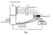
- zeigt eine erfindungsgemäße Vorrichtung zum Betreiben von LED,
- Fig. 2
- zeigt eine weitere erfindungsgemäße Vorrichtung zum Betreiben von LED, und
- Fig. 3 und 4
- zeigen erfindungsgemäße Abfolgen der PWM-Pakete.
- Fig. 1
- shows an inventive device for operating LED,
- Fig. 2
- shows a further device according to the invention for operating LED, and
- 3 and 4
- show sequences according to the invention of the PWM packets.
Nachfolgend wird die Erfindung anhand eines Ausführungsbeispiels einer Vorrichtung zum Betreiben von LEDs erklärt. Diese Vorrichtung weist ein Treiber-Modul auf, und ein von dem Treiber-Modul angesteuertes LED-Modul mit wenigstens einer LED 5, mit einem Speicher zur Hinterlegung von Informationen über das LED-Modul, wobei der Speicher entweder im Treiber-Modul oder im LED-Modul enthalten sein kann und die Informationen im Speicher abgeändert werden können.The invention will be explained with reference to an embodiment of an apparatus for operating LEDs. This device comprises a driver module, and an LED module controlled by the driver module with at least one
Der Speicher kann in einem Treiber-Modul 1 enthalten sein. Das Treiber-Modul 1 verfügt über Anschlüsse 2 und 3, an die über die Verdrahtung 4 eine LED oder mehrere LED 5 angeschlossen werden können. Die LEDs 5 können sich auf einem gemeinsamen LED-Modul befinden.The memory may be included in a
Die einzelnen LED 5 können über verschiedene Ausgangsstufen, Treiber oder Konverter angesteuert werden.The
Die Informationen im Speicher aufgrund einer Kalibrierungsmessung abgeändert werden können. Die Informationen im Speicher können um einen Korrekturfaktor abgeändert werden. Die Informationen im Speicher können um einen Korrekturfaktor abgeändert werden, der aufgrund einer Kalibrierungsmessung wurde. Der Korrekturfaktor kann von einem Benutzer geändert werden, beispielsweise über eine Vorgabe über eine Schnittstelle 7. Die Schnittstelle kann sowohl eine drahtgebundene als auch eine drahtlose Übertragung nutzen. Der Korrekturfaktor kann von der Alterung bzw. der Betriebsdauer des LED-Moduls abhängig sein. Der Korrekturfaktor kann von der Temperatur des LED-Moduls abhängig sein.The information in the memory can be changed based on a calibration measurement. The information in the memory can be changed by a correction factor. The information in the memory may be modified by a correction factor that has become due to a calibration measurement. The correction factor can be changed by a user, for example via a specification via an interface 7. The interface can use both a wired and a wireless transmission. The correction factor may depend on the aging or the operating time of the LED module. The correction factor may be dependent on the temperature of the LED module.
Für die Durchführung der Kalibrierung kann ein Sensor 6 genutzt werden, der für die Kalibrierungsmessung in das Beleuchtungssystem eingeführt wird. Der Korrekturfaktor kann von einer Farbmessung abhängig sein. Die Farbmessung kann mittels einer RGB-Farbmessung, beispielsweise eines CCD Sensors, erfolgen. In diesem Falle wäre der Sensor 6 ein RGB-Farbsensor. Die Bestimmung des Korrekturfaktors kann in regelmäßigen Abständen wiederholt werden. Der Speicher kann von dem Treiber-Modul über eine digitale Schnittstelle ausgelesen werden.To perform the calibration, a
Der Speicher kann sich auf dem LED-Modul befinden und bei Austausch des Moduls durch den Benutzer ausgelesen werden. Der Speicher kann sich auf dem LED Modul befinden und vor einem Austausch des Moduls durch das Treiber-Modul aufgrund einer Signalisierung durch den Benutzer ausgelesen werden. Der Speicher kann in einem Kalibriergerät platziert sein.The memory can be located on the LED module and can be read by the user when the module is replaced. The memory may be located on the LED module and prior to replacement of the module by the driver module due to user signaling be read out. The memory may be placed in a calibrator.
Die Signalisierung zum Auslesen des Speichers auf dem LED-Modul kann durch den Benutzer durch eine Schaltfolge an der Versorgungsspannung, einen digitalen Steuerbefehl oder durch eine andere Signalisierung erfolgen.The signaling for reading the memory on the LED module can be done by the user by a switching sequence on the supply voltage, a digital control command or by other signaling.
Nach dem Austausch des LED-Moduls können die ausgelesenen Informationen in dem Speicher des neuen LED-Moduls abgelegt werden.After replacing the LED module, the information read out can be stored in the memory of the new LED module.
Das Treiber-Modul kann die im Speicher abgelegte Information über eine digitale Schnittstelle an andere Treiber-Module weiterleiten.The driver module can forward the information stored in memory via a digital interface to other driver modules.
Zur Kalibrierung können eine oder mehrere LED Module abgeschaltet werden. Zur Kalibrierung kann jeweils auch nur ein LED Modul eingeschaltet werden.For calibration one or more LED modules can be switched off. For calibration, only one LED module can be switched on at a time.
Die Farbmessung kann mit einem Farbsensor (bspw. CCD Sensor) durchgeführt werden.The color measurement can be performed with a color sensor (eg CCD sensor).
Der Farbsensor kann so platziert ist, dass er einen Teil des von den LED Modulen abgestrahlten Lichtes empfangen kann.The color sensor may be placed so that it can receive a portion of the light emitted by the LED modules.
Der Farbsensor kann so platziert ist, dass er gegen Umgebungslicht abgeschottet ist und nur von den LED-Modulen abgestrahltes Licht empfangen kann. Diese Abschottung kann durch eine Abdeckung erfolgen, die speziell für die Kalibrierungsmessung angebracht wird. Auf dieser Abdeckung 11 kann sich der Sensor 6 befinden. Der Sensor 6 kann aber auch auf dem Reflektor 10 der LED Leuchte platziert werden. Der Sensor 6 kann so platziert sein, dass er direkt oder indirekt das Licht der LED 5 des LED-Modules empfängt.The color sensor may be placed so that it is shielded from ambient light and can receive only light emitted by the LED modules. This foreclosure can be done by a cover that is specially designed for the calibration measurement. On this cover 11, the
Bei der Kalibrierung können der Farbort und die Intensität der LED 5 gespeichert werden.During calibration, the color location and the intensity of the
Bei der Kalibrierung können die einzelnen LED Module nacheinander eingeschaltet und kalibriert werden.During calibration, the individual LED modules can be switched on and calibrated one after the other.
Die Kalibrierung kann zur Bestimmung der Farben der angeschlossenen LED-Module dienen. Dabei werden die einzelnen Farben oder Farborte sowie die Intensitäten der jeweils angesteuerten LEDs 5 bestimmt. Aus der Kombination der einzelnen Kalibrierungsmessungen, die nacheinander durchgeführt werden, kann die Zuordnung der Farben und für die Ausgabe einer gewünschten Farbe durch die LED Beleuchtung erforderliche Mischung der einzelnen LED 5 ermittelt werden.The calibration can be used to determine the colors of the connected LED modules. The individual colors or color locations as well as the intensities of the respectively driven
Es gemäß der Erfindung eine Leuchte mit LED aufgebaut werden. Das Treiber-Modul kann einen Schaltregler, beispielsweise einen AC-DC-Wandler, einen DC-DC-Wandler, eine Stromsenke oder eine Stromquelle enthalten. Das Treiber-Modul kann einen PFC (aktive Leistungsfaktorkorrekturschaltung) enthalten oder es kann dem Treiber-Modul ein PFC (aktive Leistungsfaktorkorrekturschaltung) vorgeschaltet sein. Das Treiber-Modul kann eine Potentialtrennung aufweisen.It can be constructed according to the invention, a light with LED. The driver module may include a switching regulator, such as an AC-DC converter, a DC-DC converter, a current sink, or a power source. The driver module may include a PFC (Active Power Factor Correction Circuit), or a PFC (Active Power Factor Correction Circuit) may precede the driver module. The driver module can have a potential separation.
Der Betrieb der LEDs kann derart erfolgen, daß das LED-Modul mit wenigstens einer LED von einem Treiber-Modul angesteuert wird, und ein Speicher zur Hinterlegung von Informationen über das LED-Modul vorhanden ist, wobei Informationen im Speicher abgelegt oder abgeändert werden können. Die Informationen im Speicher können aufgrund einer Kalibrierungsmessung abgeändert werden.The operation of the LEDs may be such that the LED module is driven by at least one LED from a driver module, and a memory for storing information about the LED module is present, wherein Information can be stored or modified in memory. The information in the memory can be changed based on a calibration measurement.
Das Treiber-Modul kann durch einen Schaltregler oder auch durch eine Stromsenke oder eine Stromquelle gebildet werden. Wenn als Treiber-Modul ein Schaltregler genutzt wird, dann kann dieser intern mit einer höheren Frequenz als der Frequenz arbeiten, mit der die LED oder das LED-Modul angesteuert werden. Die interne Frequenz, mit der der Schalter des Schaltreglers angesteuert wird, kann im Bereich von 10kHz bis zu einigen MHz liegen, während dieser internen Frequenz eine niedrige Frequenz überlagert wird, die der Frequenz des wenigstens einen PWM-Paketes entspricht.The driver module can be formed by a switching regulator or by a current sink or a current source. If a switching regulator is used as the driver module, then it can internally operate at a higher frequency than the frequency with which the LED or the LED module is controlled. The internal frequency with which the switch of the switching regulator is controlled, can be in the range of 10 kHz to several MHz, while this internal frequency is superimposed on a low frequency corresponding to the frequency of the at least one PWM packet.
Die Informationen im Speicher können um einen Korrekturfaktor abgeändert werden.The information in the memory can be changed by a correction factor.
Somit wird ein Verfahren zum Betrieb von wenigstens zwei Leuchtmitteln ermöglicht, wobei durch eine gemeinsame elektrische Versorgungseinheit elektrische Energie an wenigstens zwei Leuchtmittelanordnungen, jeweils bestehend aus einem oder mehreren Leuchtmitteln, zur Verfügung gestellt wird, wobei einer ersten Leuchtmittelanordnung und wenigstens einer zweiten Leuchtmittelanordnung elektrische Energie in Form von PWM-Paketen zugeführt wird, wobei zwischen den unterschiedlichen Leuchtmittelanordnungen die zeitliche Abfolge der PWM-Pakete abgestimmt ist.Thus, a method for operating at least two light sources is made possible, wherein electric energy is provided to at least two illuminant arrangements, each consisting of one or more bulbs, by a common electrical supply unit, wherein a first illuminant arrangement and at least one second illuminant arrangement contains electrical energy Form of PWM packets is supplied, wherein the timing of the PWM packets is tuned between the different illuminant arrangements.
Beispiele für die Ansteuerung von drei Leuchtmittelanordnungen sind in den
Die wenigstens zwei Leuchtmittelanordnungen können so angesteuert werden, dass der zeitliche Mittelpunkt eines PWM-Pakets der ersten Leuchtmittelanordnung mit dem zeitlichen Mittelpunkt eines PWM-Pakets wenigstens einer zweiten Leuchtmittelanordnung übereinstimmt bzw. zeitlich nah aufeinanderfolgt. In
Die Abstimmung der zeitlichen Abfolge der PWM-Pakete kann über den gesamten Dimmbereich der Leuchtmittel erfolgen.The timing of the PWM packets can be coordinated over the entire dimming range of the lamps.
Die wenigstens zwei Leuchtmittelanordnungen können so angesteuert werden, dass alternativ oder zusätzlich die zeitlichen Mittelpunkte der PWM-Pakete der Leuchtmittelanordnungen mit einem Offset-Wert zeitlich gegeneinander verschoben sind, damit die Flanken der PWM-Pakete an die Leuchtmittelanordnungen nicht zeitgleich erfolgen.The at least two illuminant arrangements can be controlled such that, alternatively or additionally, the time centers of the PWM packets of the illuminant arrangements are shifted in time with respect to one another with an offset value, so that the flanks of the PWM packets to the illuminant arrangements do not occur at the same time.
Es kann wenigstens zeitweise die Einschaltflanke wenigstens eines von mehreren parallelen PWM-Signalen (d.h. die die PWM-Pakete etnhaltenden Signale) zeitlich zu wenigstens einem weiteren PWM-Signal verschoben sein, so dass das Problem der simultanen PWM-Ansteuerung nicht mehr besteht. Dieser Versatz (Offset-Wert) kann intern oder extern variierbar sein oder aber fest vorgegeben sein. Insbesondere könnte beispielsweise der Versatz der gesamten Ausschaltphase eines PWM-Signals entsprechen, d.h., bei unverändertem Tastverhältnis wird die entsprechende LED innerhalb einer PWM-Periode zunächst ausgeschaltet und dann eingeschaltet. Ein PWM-Signal kann also invertiert sein, d.h. beim Start eines jeden Zyklus, getriggert bspw. durch ein Interrupt-Signal, kann zuerst die Ausschaltphase und erst dann die Einschaltphase der LED angesteuert werden.At least temporarily, the switch-on edge of at least one of a plurality of parallel PWM signals (ie, the signals containing the PWM packets) may be shifted in time to at least one further PWM signal, so that the problem of simultaneous PWM control no longer exists. This offset (offset value) can be internally or externally variable or fixed. In particular, for example, the offset could correspond to the entire turn-off phase of a PWM signal, ie, with the pulse duty ratio unchanged, the corresponding LED within a PWM period becomes first switched off and then turned on. A PWM signal can therefore be inverted, ie at the start of each cycle, triggered by an interrupt signal, for example, the switch-off phase and only then the switch-on phase of the LED can be controlled.
Alternativ hierzu könnte der Versatz auch derart gewählt werden, dass die Einschaltflanken für die PWM-Signale gleichmäßig verteilt über die PWM-Periode generiert werden. Eine dritte Alternative besteht darin, denn Versatz zufällig zu wählen. In
Der Versatz kann bereits bei der Erzeugung der PWM-Signale vorliegen, oder aber bei simultan erzeugten PWM-Signalen auf der Strecke zwischen der PWM-Erzeugung und den LEDs gezielt eingefügt werden.The offset may already be present during the generation of the PWM signals, or else be inserted deliberately in the case of simultaneously generated PWM signals on the path between the PWM generation and the LEDs.
Die PWM-Signale können ausgehend von einem oder aber auch von mehreren Taktgebern erzeugt werden.The PWM signals can be generated starting from one or even from several clocks.
Der Offset-Wert kann abhängig vom Dimmlevel der Leuchtmittel gewählt werden.The offset value can be selected depending on the dimming level of the lamps.
Es kann fakultativ sich auch die Frequenz wenigstens eines PWM-Signals wenigstens zeitweise zeitlich verändern, so dass eine kombinierte PWM/FM (Frequenzmodulation vorliegt). Dabei wäre es beispielsweise denkbar, die Frequenz abhängig von dem Tastverhältnis des PWM-Signals einzustellen.Optionally, the frequency of at least one PWM signal may also change at least temporarily, so that a combined PWM / FM (frequency modulation) is present. It would be conceivable, for example, to set the frequency as a function of the duty cycle of the PWM signal.
Zusätzlich kann sich auch die Frequenz wenigstens eines PWM-Signals wenigstens zeitweise von der wenigstens eines weiteren PWM-Signals unterscheiden. Dazu kann wiederum ein oder mehrere Taktgeber vorliegen. Bspw. kann eine Frequenz das Vielfache einer weiteren Frequenz betragen. Wenigstens eine Frequenz kann nach Erzeugung einheitlicher PWM-Schaltfrequenzen bspw. durch einen Kondensator verschoben werden.In addition, the frequency of at least one PWM signal at least temporarily from the distinguish at least one other PWM signal. In turn, one or more clocks may be present. For example. For example, one frequency may be a multiple of another frequency. At least one frequency can be shifted after generation of uniform PWM switching frequencies, for example by a capacitor.
Eine rein beispielsweise geschilderte und keineswegs einschränkende Implementierung kann bspw. wie folgt sein:
- Für jeden PWM-Kanal oder wenigstens einen abweichenden PWM-Kanal kann unabhängig der notwendige PWM-Stellwert gerechnet wird und das Resultat in ein Hardwareregister geschrieben wird.
- For each PWM channel or at least one deviating PWM channel, the required PWM control value can be calculated independently and the result written to a hardware register.
Die Hardware übernimmt dann den neuen Wert beim Nächsten Nulldurchgang der Periode. Durch das Center PWM Verfahren (Dreieck wie in
Diese Verschiebung kann man dann z.B. pro Periode zusätzlich noch abändern, sodass der Mittelwert über die Zeit wiederum Stabil ist. ![]()
da der Step dann alle 10ms ist, sollte es noch nicht als Flackern wahrgenommen werden, zudem wählen wir die Auflösung jeweils recht hoch, sodass ein Bit Versatz nicht viel ausmachen dürfte.This shift can then be changed, for example, per period additionally, so that the mean value over time is again stable. ![]()
since the step is then every 10ms, it should not be perceived as a flicker yet, we also choose the resolution quite high, so that a bit offset should not make much.
Die Leuchtmittel der ersten und/oder wenigstens der zweiten Leuchtmittelanordnung können anorganische oder organische Leuchtdioden sein.The luminous means of the first and / or at least the second luminous means arrangement can be inorganic or organic light-emitting diodes.
Die Leuchtmittel der ersten und/oder wenigstens der zweiten Leuchtmittelanordnung können ein unterschiedliches Lichtspektrum emittieren.The lighting means of the first and / or at least the second lighting arrangement can emit a different light spectrum.
Somit kann ein Betriebsgerät ermöglicht werden, in dem oben angeführte Verfahren durchgeführt werden können.Thus, an operating device can be made possible in the above-mentioned method can be performed.
Somit kann ein Beleuchtungssystem ermöglicht werden, welches wenigstens zwei Leuchtmittel aufweist, in dem ein oben angeführtes Verfahren bzw. Betriebsgerät zur Anwendung gelangt.Thus, an illumination system can be made possible which has at least two light sources in which a method or operating device mentioned above is used.
In
Der Betriebsschaltung wird eine Eingangs-Gleichspannung Vin zugeführt, die natürlich auch eine gleichgerichtete Wechselspannung sein kann.The operating circuit is supplied with an input DC voltage Vin, which of course can also be a rectified AC voltage.
Eine Serienschaltung zwischen einem HalbleiterLeistungsschalter S1 (beispielsweise einem MOSFET) und einer Freilaufdiode D1 energetisiert in eingeschaltetem Zustand des Schalters S1 eine Induktivität L1 mittels des durch den Schalter fliessenden Stroms. Im ausgeschalteten Zustand des Schalters S1 entlädt sich die in der Spule L1 gespeicherte Energie in Form eines Stroms i durch einen Kondensator C1 und die Leuchtdiodenstrecke LED.A series circuit between a semiconductor power switch S1 (for example, a MOSFET) and a freewheeling diode D1 energizes in the switched-on state of the switch S1 an inductance L1 by means of the current flowing through the switch. In the switched-off state of the switch S1, the energy stored in the coil L1 discharges in the form of a current i through a capacitor C1 and the light-emitting diode path LED.
Es ist eine Steuer- und/oder Regelschaltung SR vorgesehen, die als Stellgrösse der Regelung der Leuchtdiodenleistung die Taktung des Schalters S1 beispielsweise in Form von hochfreugenten modulierten Signalen vorgibt. Die Steuer- und/oder Regelschaltung SR kann beispielsweise eine hysteretische Stromregelung anwenden.There is provided a control and / or regulating circuit SR, which specifies the timing of the switch S1, for example in the form of hochfreugenten modulated signals as a manipulated variable of the control of the LED power. The control and / or regulating circuit SR can, for example, apply a hysteretic current regulation.
Mittels eines Messwiderstands RS erfasst die Steuer- und/oder Regelschaltung SR den Strom durch den Schalter S1 (im eingeschalteten Zustand des Schalters S1).By means of a measuring resistor RS, the control and / or regulating circuit SR detects the current through the switch S1 (in the switched-on state of the switch S1).
Über einen Spannungsteiler R1, R2 kann die Steuer- und/oder Regeleinheit SR das Potential auf der potentialniedrigeren Seite der LED-Strecke erfassen.Via a voltage divider R1, R2, the control and / or regulating unit SR can detect the potential on the lower-potential side of the LED path.
Ein weiterer Spannungsteiler R3, R4 ermöglicht die Erfassung der Versorgungsspannung.Another voltage divider R3, R4 allows the detection of the supply voltage.
Das Treiber-Modul wird in diesem Beispiel durch einen Buck-Konverter gebildet, kann aber auch beispielweise durch einen Boost-Konverter, Buck-Boost-Konverter oder anderen Schaltregler oder auch durch eine Stromsenke oder eine Stromquelle gebildet werden. Der Schalter S1 wird intern durch die Steuer- und/oder Regelschaltung SR mit einer höheren Frequenz als der Frequenz angesteuert, als mit der die LED oder das LED-Modul angesteuert werden. Die interne Frequenz, mit der der Schalter S1 des Schaltreglers angesteuert wird, kann im Bereich von 10kHz bis zu einigen MHz liegen, während dieser internen Frequenz eine niedrige Frequenz überlagert wird, die der Frequenz des wenigstens einen PWM-Paketes entspricht. Somit kann das LED-Modul mit einem PWM-Paket mit niedriger Frequenz angesteuert werden, wobei das PWM-Paket einen Rippel aufgrund des hochfrequenten Betriebes des Schalters S1 des Treiber-Moduls während der Einschaltzeit aufweisen kann. Der Rippel, der sich aufgrund des hochfrequenten Betriebes des Schalters S1 des Treiber-Moduls ergeben kann, kann durch den Kondensator C1 verringert werden.The driver module is formed in this example by a buck converter, but can also be formed for example by a boost converter, buck-boost converter or other switching regulator or by a current sink or a power source. The switch S1 is driven internally by the control and / or regulating circuit SR at a higher frequency than the frequency, as with which the LED or the LED module are controlled. The internal frequency with which the switch S1 of the switching regulator is controlled may be in the range of 10 kHz to several MHz, while this internal frequency is superimposed on a low frequency which corresponds to the frequency of the at least one PWM packet. Thus, the LED module may be driven with a low frequency PWM packet, which PWM packet may ripple due to the high frequency operation of the switch S1 of the driver module during turn-on time. The ripple that may result due to the high frequency operation of the switch S1 of the driver module may be reduced by the capacitor C1.
Die niedrige Frequenz des wenigstens einen PWM-Paketes, die überlagert wird, kann durch einen externen Controller wie beispielsweise einen Microcontroller oder eine andere zentrale Steuereinheit vorgegeben werden. Durch die Ansteuerung des Treiber-Modul mit solchen niederfrequenten PWM-Paketen kann das Treiber-Modul zeitweise deaktiviert werden und somit durch die PWM-Pakete eine Helligkeitssteuerung und bei Einsatz verschiedener Lichtspektren der Leuchtmittel eine Farbmischung erreicht werden.The low frequency of the at least one PWM packet that is superimposed may be dictated by an external controller such as a microcontroller or other central control unit. By controlling the driver module with such low-frequency PWM packets, the driver module can be temporarily deactivated and thus a brightness control can be achieved by the PWM packets and color mixing using different light spectra of the lamps.
Beispielsweise können für eine RGB-Farbmischung die drei Farben des RGB-LED-Moduls von jeweils einem Treiber-Modul angesteuert werden, wobei die drei Treiber-Module über drei PWM-Kanäle angesteuert werden.For example, for RGB color mixing, the three colors of the RGB LED module can each be driven by one driver module, the three driver modules being controlled via three PWM channels.
Claims (12)
- Device for operating at least two illuminant arrangements, each consisting of one or more illuminants, preferably LEDs, wherein the device makes electrical energy available to the at least two illuminant arrangements,
and wherein electrical energy in the form of PWM packets is fed to a first illuminant arrangement and at least one second illuminant arrangement,
characterized
in that the switch-on edge of at least one PWM packet of a first illuminant arrangement deviates at least occasionally from the switch-on edge of at least one further PWM packet of a second illuminant arrangement, wherein the at least two illuminant arrangements are driven such that the temporal midpoint of a PWM packet of the first illuminant arrangement corresponds to or temporally closely follows the temporal midpoint of a PWM packet of at least one second illuminant arrangement. - Device according to Claim 1, characterized in that the temporal sequence of the PWM packets is co-ordinated over the entire dimming range of the illuminants.
- Device according to either of the preceding claims, characterized in that the at least two illuminant arrangements are driven such that in addition the temporal midpoints of the PWM packets of the illuminant arrangements are temporally shifted relative to one another with an offset value, in order that the edges of the PWM packets to the illuminant arrangements are not effected simultaneously,
wherein the offset value is chosen depending on the dimming level of the illuminants. - Device according to any of the preceding claims, characterized in that the illuminants of the first and/or at least the second illuminant arrangement(s) are inorganic or organic light-emitting diodes.
- Device according to any of the preceding claims, characterized in that the illuminants of the first and/or at least the second illuminant arrangement(s) emit a different light spectrum.
- Device according to any of the preceding claims, wherein the temporal deviation of the switch-on edge is internally or externally variable or is fixedly predefined.
- Device according to any of the preceding claims, wherein the temporal deviation is already present when the PWM signals are generated, and/or is inserted in a targeted manner on the path between the PWM generation and the LEDs.
- Device according to any of the preceding claims, characterized
in that the frequency of at least one PWM packet deviates at least occasionally from the frequency of at least one further PWM packet of a second illuminant arrangement,
wherein the frequency of one PWM packet is the multiple of a further frequency. - Device according to Claim 8,
wherein at least one frequency is shifted after the generation of uniform PWM switching frequencies e.g. by a capacitor. - Operating unit, comprising a device according to any of the preceding claims.
- Lighting system comprising at least two illuminants and two functionally interconnected devices according to any of Claims 1 to 9.
- Method for reducing the loading of a voltage supply and/or for improving the EMC compatibility when driving LEDs with PWM signals,
wherein the switch-on edge of at least one PWM signal deviates temporally from the at least one further PWM signal at least occasionally and is therefore not simultaneous,
wherein the at least two illuminant arrangements are driven such that the temporal midpoint of a PWM packet of the first illuminant arrangement corresponds to or temporally closely follows the temporal midpoint of a PWM packet of at least one second illuminant arrangement.
Applications Claiming Priority (3)
| Application Number | Priority Date | Filing Date | Title |
|---|---|---|---|
| AT7462008 | 2008-12-23 | ||
| DE102009005819A DE102009005819A1 (en) | 2008-12-23 | 2009-01-22 | Method and device for operating LEDs |
| PCT/EP2009/067631 WO2010081613A1 (en) | 2008-12-23 | 2009-12-21 | Processor and device for operating groups of leds using pwm |
Publications (2)
| Publication Number | Publication Date |
|---|---|
| EP2368407A1 EP2368407A1 (en) | 2011-09-28 |
| EP2368407B1 true EP2368407B1 (en) | 2014-03-19 |
Family
ID=42220959
Family Applications (1)
| Application Number | Title | Priority Date | Filing Date |
|---|---|---|---|
| EP09799347.1A Active EP2368407B1 (en) | 2008-12-23 | 2009-12-21 | Processor and device for operating groups of leds using pwm |
Country Status (3)
| Country | Link |
|---|---|
| EP (1) | EP2368407B1 (en) |
| DE (2) | DE102009005819A1 (en) |
| WO (1) | WO2010081613A1 (en) |
Family Cites Families (6)
| Publication number | Priority date | Publication date | Assignee | Title |
|---|---|---|---|---|
| WO1994018809A1 (en) | 1993-02-11 | 1994-08-18 | Phares Louis A | Controlled lighting system |
| US6016038A (en) | 1997-08-26 | 2000-01-18 | Color Kinetics, Inc. | Multicolored LED lighting method and apparatus |
| TWI277225B (en) * | 2005-08-03 | 2007-03-21 | Beyond Innovation Tech Co Ltd | Apparatus of light source and adjustable control circuit for LEDs |
| DE102005049579A1 (en) * | 2005-10-17 | 2007-04-19 | Patent-Treuhand-Gesellschaft für elektrische Glühlampen mbH | Light source that emits mixed-color light, and methods for controlling the color location of such a light source |
| US20080048582A1 (en) * | 2006-08-28 | 2008-02-28 | Robinson Shane P | Pwm method and apparatus, and light source driven thereby |
| US7948468B2 (en) * | 2007-02-23 | 2011-05-24 | The Regents Of The University Of Colorado | Systems and methods for driving multiple solid-state light sources |
-
2009
- 2009-01-22 DE DE102009005819A patent/DE102009005819A1/en not_active Withdrawn
- 2009-12-21 EP EP09799347.1A patent/EP2368407B1/en active Active
- 2009-12-21 WO PCT/EP2009/067631 patent/WO2010081613A1/en active Application Filing
- 2009-12-21 DE DE112009003815T patent/DE112009003815A5/en not_active Withdrawn
Also Published As
| Publication number | Publication date |
|---|---|
| WO2010081613A1 (en) | 2010-07-22 |
| DE112009003815A5 (en) | 2012-08-02 |
| DE102009005819A1 (en) | 2010-07-01 |
| EP2368407A1 (en) | 2011-09-28 |
Similar Documents
| Publication | Publication Date | Title |
|---|---|---|
| DE10013207B4 (en) | Control of light emitting diodes (LEDs) | |
| EP2474200B1 (en) | Operation of a pulse-width-modulated led | |
| EP2019569B1 (en) | Method for dimming light emitted by LED lights, in particular in the cabin of a commercial airplane | |
| EP2792217B1 (en) | Lighting devices including boost converters to control chromaticity and/or brightness and related methods | |
| EP2522199B1 (en) | Combined method for operating an electric illuminant and operating circuit | |
| US8796957B2 (en) | Multi-string LED driving method and system | |
| DE102016112550A1 (en) | LIGHTING ASSEMBLY, VEHICLE LIGHTING DEVICE AND VEHICLE | |
| DE102009000042A1 (en) | Multiple LED driver | |
| DE112014002525T5 (en) | A control circuit and method for generating a voltage for a light-emitting diode illumination device | |
| EP2548412B1 (en) | Led-lighting system | |
| EP2772120B1 (en) | Pwm dimming of light-emitting means | |
| DE102012018760A1 (en) | Device for operating e.g. organic LED in lighting system for lighting room, has supply unit supplying power to LED, where amount of supplied power in mode is differentiated from amount of supplied power in other mode with reference input | |
| EP2280585A2 (en) | Method for adjusting the operation of multiple lights | |
| DE102016125547A1 (en) | POWER SUPPLY AND LIGHT | |
| DE202013004095U1 (en) | LED lighting system | |
| EP3064038B1 (en) | Illuminating means operating circuit having a clocked converter for the digital adjustment of a color temperature and/or a dimming level | |
| EP2368407B1 (en) | Processor and device for operating groups of leds using pwm | |
| EP2425679B1 (en) | Driver circuit for an led | |
| DE202017002443U1 (en) | Circuit arrangement for operating a light source | |
| EP2777364B1 (en) | Method for operating at least one led by means of dithering | |
| DE102017223405A1 (en) | Operating circuit for an LED light source | |
| DE102018115672A1 (en) | Control gear for several illuminants, illuminants and lighting system | |
| EP4099803A1 (en) | Tunable white led module | |
| DE102014208305A1 (en) | Capacitance-free LED driver | |
| EP2428098B1 (en) | Device for operating leds |
Legal Events
| Date | Code | Title | Description |
|---|---|---|---|
| PUAI | Public reference made under article 153(3) epc to a published international application that has entered the european phase |
Free format text: ORIGINAL CODE: 0009012 |
|
| 17P | Request for examination filed |
Effective date: 20110609 |
|
| AK | Designated contracting states |
Kind code of ref document: A1 Designated state(s): AT BE BG CH CY CZ DE DK EE ES FI FR GB GR HR HU IE IS IT LI LT LU LV MC MK MT NL NO PL PT RO SE SI SK SM TR |
|
| DAX | Request for extension of the european patent (deleted) | ||
| 17Q | First examination report despatched |
Effective date: 20120417 |
|
| GRAP | Despatch of communication of intention to grant a patent |
Free format text: ORIGINAL CODE: EPIDOSNIGR1 |
|
| INTG | Intention to grant announced |
Effective date: 20131018 |
|
| GRAS | Grant fee paid |
Free format text: ORIGINAL CODE: EPIDOSNIGR3 |
|
| GRAA | (expected) grant |
Free format text: ORIGINAL CODE: 0009210 |
|
| AK | Designated contracting states |
Kind code of ref document: B1 Designated state(s): AT BE BG CH CY CZ DE DK EE ES FI FR GB GR HR HU IE IS IT LI LT LU LV MC MK MT NL NO PL PT RO SE SI SK SM TR |
|
| REG | Reference to a national code |
Ref country code: GB Ref legal event code: FG4D Free format text: NOT ENGLISH |
|
| REG | Reference to a national code |
Ref country code: CH Ref legal event code: EP |
|
| REG | Reference to a national code |
Ref country code: IE Ref legal event code: FG4D Free format text: LANGUAGE OF EP DOCUMENT: GERMAN |
|
| REG | Reference to a national code |
Ref country code: AT Ref legal event code: REF Ref document number: 658398 Country of ref document: AT Kind code of ref document: T Effective date: 20140415 |
|
| REG | Reference to a national code |
Ref country code: DE Ref legal event code: R096 Ref document number: 502009009040 Country of ref document: DE Effective date: 20140430 |
|
| PG25 | Lapsed in a contracting state [announced via postgrant information from national office to epo] |
Ref country code: LT Free format text: LAPSE BECAUSE OF FAILURE TO SUBMIT A TRANSLATION OF THE DESCRIPTION OR TO PAY THE FEE WITHIN THE PRESCRIBED TIME-LIMIT Effective date: 20140319 Ref country code: NO Free format text: LAPSE BECAUSE OF FAILURE TO SUBMIT A TRANSLATION OF THE DESCRIPTION OR TO PAY THE FEE WITHIN THE PRESCRIBED TIME-LIMIT Effective date: 20140619 |
|
| REG | Reference to a national code |
Ref country code: NL Ref legal event code: VDEP Effective date: 20140319 |
|
| REG | Reference to a national code |
Ref country code: LT Ref legal event code: MG4D |
|
| PG25 | Lapsed in a contracting state [announced via postgrant information from national office to epo] |
Ref country code: CY Free format text: LAPSE BECAUSE OF FAILURE TO SUBMIT A TRANSLATION OF THE DESCRIPTION OR TO PAY THE FEE WITHIN THE PRESCRIBED TIME-LIMIT Effective date: 20140319 Ref country code: FI Free format text: LAPSE BECAUSE OF FAILURE TO SUBMIT A TRANSLATION OF THE DESCRIPTION OR TO PAY THE FEE WITHIN THE PRESCRIBED TIME-LIMIT Effective date: 20140319 Ref country code: SE Free format text: LAPSE BECAUSE OF FAILURE TO SUBMIT A TRANSLATION OF THE DESCRIPTION OR TO PAY THE FEE WITHIN THE PRESCRIBED TIME-LIMIT Effective date: 20140319 |
|
| PG25 | Lapsed in a contracting state [announced via postgrant information from national office to epo] |
Ref country code: HR Free format text: LAPSE BECAUSE OF FAILURE TO SUBMIT A TRANSLATION OF THE DESCRIPTION OR TO PAY THE FEE WITHIN THE PRESCRIBED TIME-LIMIT Effective date: 20140319 Ref country code: LV Free format text: LAPSE BECAUSE OF FAILURE TO SUBMIT A TRANSLATION OF THE DESCRIPTION OR TO PAY THE FEE WITHIN THE PRESCRIBED TIME-LIMIT Effective date: 20140319 |
|
| PG25 | Lapsed in a contracting state [announced via postgrant information from national office to epo] |
Ref country code: NL Free format text: LAPSE BECAUSE OF FAILURE TO SUBMIT A TRANSLATION OF THE DESCRIPTION OR TO PAY THE FEE WITHIN THE PRESCRIBED TIME-LIMIT Effective date: 20140319 Ref country code: CZ Free format text: LAPSE BECAUSE OF FAILURE TO SUBMIT A TRANSLATION OF THE DESCRIPTION OR TO PAY THE FEE WITHIN THE PRESCRIBED TIME-LIMIT Effective date: 20140319 Ref country code: BG Free format text: LAPSE BECAUSE OF FAILURE TO SUBMIT A TRANSLATION OF THE DESCRIPTION OR TO PAY THE FEE WITHIN THE PRESCRIBED TIME-LIMIT Effective date: 20140619 Ref country code: IS Free format text: LAPSE BECAUSE OF FAILURE TO SUBMIT A TRANSLATION OF THE DESCRIPTION OR TO PAY THE FEE WITHIN THE PRESCRIBED TIME-LIMIT Effective date: 20140719 Ref country code: RO Free format text: LAPSE BECAUSE OF FAILURE TO SUBMIT A TRANSLATION OF THE DESCRIPTION OR TO PAY THE FEE WITHIN THE PRESCRIBED TIME-LIMIT Effective date: 20140319 Ref country code: EE Free format text: LAPSE BECAUSE OF FAILURE TO SUBMIT A TRANSLATION OF THE DESCRIPTION OR TO PAY THE FEE WITHIN THE PRESCRIBED TIME-LIMIT Effective date: 20140319 |
|
| PG25 | Lapsed in a contracting state [announced via postgrant information from national office to epo] |
Ref country code: SK Free format text: LAPSE BECAUSE OF FAILURE TO SUBMIT A TRANSLATION OF THE DESCRIPTION OR TO PAY THE FEE WITHIN THE PRESCRIBED TIME-LIMIT Effective date: 20140319 Ref country code: PL Free format text: LAPSE BECAUSE OF FAILURE TO SUBMIT A TRANSLATION OF THE DESCRIPTION OR TO PAY THE FEE WITHIN THE PRESCRIBED TIME-LIMIT Effective date: 20140319 Ref country code: ES Free format text: LAPSE BECAUSE OF FAILURE TO SUBMIT A TRANSLATION OF THE DESCRIPTION OR TO PAY THE FEE WITHIN THE PRESCRIBED TIME-LIMIT Effective date: 20140319 |
|
| REG | Reference to a national code |
Ref country code: DE Ref legal event code: R097 Ref document number: 502009009040 Country of ref document: DE |
|
| PG25 | Lapsed in a contracting state [announced via postgrant information from national office to epo] |
Ref country code: PT Free format text: LAPSE BECAUSE OF FAILURE TO SUBMIT A TRANSLATION OF THE DESCRIPTION OR TO PAY THE FEE WITHIN THE PRESCRIBED TIME-LIMIT Effective date: 20140721 |
|
| PLBE | No opposition filed within time limit |
Free format text: ORIGINAL CODE: 0009261 |
|
| STAA | Information on the status of an ep patent application or granted ep patent |
Free format text: STATUS: NO OPPOSITION FILED WITHIN TIME LIMIT |
|
| PG25 | Lapsed in a contracting state [announced via postgrant information from national office to epo] |
Ref country code: DK Free format text: LAPSE BECAUSE OF FAILURE TO SUBMIT A TRANSLATION OF THE DESCRIPTION OR TO PAY THE FEE WITHIN THE PRESCRIBED TIME-LIMIT Effective date: 20140319 |
|
| 26N | No opposition filed |
Effective date: 20141222 |
|
| PG25 | Lapsed in a contracting state [announced via postgrant information from national office to epo] |
Ref country code: IT Free format text: LAPSE BECAUSE OF FAILURE TO SUBMIT A TRANSLATION OF THE DESCRIPTION OR TO PAY THE FEE WITHIN THE PRESCRIBED TIME-LIMIT Effective date: 20140319 |
|
| REG | Reference to a national code |
Ref country code: DE Ref legal event code: R097 Ref document number: 502009009040 Country of ref document: DE Effective date: 20141222 |
|
| PG25 | Lapsed in a contracting state [announced via postgrant information from national office to epo] |
Ref country code: BE Free format text: LAPSE BECAUSE OF NON-PAYMENT OF DUE FEES Effective date: 20141231 |
|
| PG25 | Lapsed in a contracting state [announced via postgrant information from national office to epo] |
Ref country code: LU Free format text: LAPSE BECAUSE OF FAILURE TO SUBMIT A TRANSLATION OF THE DESCRIPTION OR TO PAY THE FEE WITHIN THE PRESCRIBED TIME-LIMIT Effective date: 20141221 Ref country code: SI Free format text: LAPSE BECAUSE OF FAILURE TO SUBMIT A TRANSLATION OF THE DESCRIPTION OR TO PAY THE FEE WITHIN THE PRESCRIBED TIME-LIMIT Effective date: 20140319 |
|
| REG | Reference to a national code |
Ref country code: CH Ref legal event code: PL |
|
| REG | Reference to a national code |
Ref country code: IE Ref legal event code: MM4A |
|
| PG25 | Lapsed in a contracting state [announced via postgrant information from national office to epo] |
Ref country code: CH Free format text: LAPSE BECAUSE OF NON-PAYMENT OF DUE FEES Effective date: 20141231 Ref country code: LI Free format text: LAPSE BECAUSE OF NON-PAYMENT OF DUE FEES Effective date: 20141231 Ref country code: IE Free format text: LAPSE BECAUSE OF NON-PAYMENT OF DUE FEES Effective date: 20141221 |
|
| REG | Reference to a national code |
Ref country code: FR Ref legal event code: PLFP Year of fee payment: 7 |
|
| PG25 | Lapsed in a contracting state [announced via postgrant information from national office to epo] |
Ref country code: SM Free format text: LAPSE BECAUSE OF FAILURE TO SUBMIT A TRANSLATION OF THE DESCRIPTION OR TO PAY THE FEE WITHIN THE PRESCRIBED TIME-LIMIT Effective date: 20140319 |
|
| PG25 | Lapsed in a contracting state [announced via postgrant information from national office to epo] |
Ref country code: MC Free format text: LAPSE BECAUSE OF FAILURE TO SUBMIT A TRANSLATION OF THE DESCRIPTION OR TO PAY THE FEE WITHIN THE PRESCRIBED TIME-LIMIT Effective date: 20140319 |
|
| PG25 | Lapsed in a contracting state [announced via postgrant information from national office to epo] |
Ref country code: GR Free format text: LAPSE BECAUSE OF FAILURE TO SUBMIT A TRANSLATION OF THE DESCRIPTION OR TO PAY THE FEE WITHIN THE PRESCRIBED TIME-LIMIT Effective date: 20140620 |
|
| PG25 | Lapsed in a contracting state [announced via postgrant information from national office to epo] |
Ref country code: MT Free format text: LAPSE BECAUSE OF FAILURE TO SUBMIT A TRANSLATION OF THE DESCRIPTION OR TO PAY THE FEE WITHIN THE PRESCRIBED TIME-LIMIT Effective date: 20140319 Ref country code: TR Free format text: LAPSE BECAUSE OF FAILURE TO SUBMIT A TRANSLATION OF THE DESCRIPTION OR TO PAY THE FEE WITHIN THE PRESCRIBED TIME-LIMIT Effective date: 20140319 Ref country code: HU Free format text: LAPSE BECAUSE OF FAILURE TO SUBMIT A TRANSLATION OF THE DESCRIPTION OR TO PAY THE FEE WITHIN THE PRESCRIBED TIME-LIMIT; INVALID AB INITIO Effective date: 20091221 |
|
| REG | Reference to a national code |
Ref country code: FR Ref legal event code: PLFP Year of fee payment: 8 |
|
| REG | Reference to a national code |
Ref country code: FR Ref legal event code: PLFP Year of fee payment: 9 |
|
| PGFP | Annual fee paid to national office [announced via postgrant information from national office to epo] |
Ref country code: AT Payment date: 20171228 Year of fee payment: 9 |
|
| PG25 | Lapsed in a contracting state [announced via postgrant information from national office to epo] |
Ref country code: MK Free format text: LAPSE BECAUSE OF FAILURE TO SUBMIT A TRANSLATION OF THE DESCRIPTION OR TO PAY THE FEE WITHIN THE PRESCRIBED TIME-LIMIT Effective date: 20140319 |
|
| REG | Reference to a national code |
Ref country code: DE Ref legal event code: R084 Ref document number: 502009009040 Country of ref document: DE |
|
| PGFP | Annual fee paid to national office [announced via postgrant information from national office to epo] |
Ref country code: FR Payment date: 20181231 Year of fee payment: 10 |
|
| REG | Reference to a national code |
Ref country code: AT Ref legal event code: MM01 Ref document number: 658398 Country of ref document: AT Kind code of ref document: T Effective date: 20181221 |
|
| REG | Reference to a national code |
Ref country code: DE Ref legal event code: R079 Ref document number: 502009009040 Country of ref document: DE Free format text: PREVIOUS MAIN CLASS: H05B0033080000 Ipc: H05B0045000000 |
|
| PG25 | Lapsed in a contracting state [announced via postgrant information from national office to epo] |
Ref country code: AT Free format text: LAPSE BECAUSE OF NON-PAYMENT OF DUE FEES Effective date: 20181221 |
|
| PGFP | Annual fee paid to national office [announced via postgrant information from national office to epo] |
Ref country code: GB Payment date: 20191226 Year of fee payment: 11 |
|
| PG25 | Lapsed in a contracting state [announced via postgrant information from national office to epo] |
Ref country code: FR Free format text: LAPSE BECAUSE OF NON-PAYMENT OF DUE FEES Effective date: 20191231 |
|
| GBPC | Gb: european patent ceased through non-payment of renewal fee |
Effective date: 20201221 |
|
| PG25 | Lapsed in a contracting state [announced via postgrant information from national office to epo] |
Ref country code: GB Free format text: LAPSE BECAUSE OF NON-PAYMENT OF DUE FEES Effective date: 20201221 |
|
| PGFP | Annual fee paid to national office [announced via postgrant information from national office to epo] |
Ref country code: DE Payment date: 20220527 Year of fee payment: 14 |
|
| P01 | Opt-out of the competence of the unified patent court (upc) registered |
Effective date: 20230530 |