EP2368210B1 - Method for actuating an rfid antenna, and an associated rfid antenna system - Google Patents
Method for actuating an rfid antenna, and an associated rfid antenna system Download PDFInfo
- Publication number
- EP2368210B1 EP2368210B1 EP09752742A EP09752742A EP2368210B1 EP 2368210 B1 EP2368210 B1 EP 2368210B1 EP 09752742 A EP09752742 A EP 09752742A EP 09752742 A EP09752742 A EP 09752742A EP 2368210 B1 EP2368210 B1 EP 2368210B1
- Authority
- EP
- European Patent Office
- Prior art keywords
- antenna
- reader
- network
- handed
- side port
- Prior art date
- Legal status (The legal status is an assumption and is not a legal conclusion. Google has not performed a legal analysis and makes no representation as to the accuracy of the status listed.)
- Active
Links
- 238000000034 method Methods 0.000 title claims description 19
- 230000010287 polarization Effects 0.000 claims description 25
- 238000011144 upstream manufacturing Methods 0.000 claims description 8
- 230000003213 activating effect Effects 0.000 claims 1
- 230000005540 biological transmission Effects 0.000 description 11
- 238000001514 detection method Methods 0.000 description 3
- 230000000712 assembly Effects 0.000 description 2
- 238000000429 assembly Methods 0.000 description 2
- 239000000969 carrier Substances 0.000 description 2
- 238000010276 construction Methods 0.000 description 2
- 230000002457 bidirectional effect Effects 0.000 description 1
- 238000004891 communication Methods 0.000 description 1
- 238000007796 conventional method Methods 0.000 description 1
- 230000005672 electromagnetic field Effects 0.000 description 1
- 238000005516 engineering process Methods 0.000 description 1
- 238000012544 monitoring process Methods 0.000 description 1
- 230000005855 radiation Effects 0.000 description 1
- 239000000758 substrate Substances 0.000 description 1
- 230000007704 transition Effects 0.000 description 1
Images


Classifications
-
- G—PHYSICS
- G06—COMPUTING; CALCULATING OR COUNTING
- G06K—GRAPHICAL DATA READING; PRESENTATION OF DATA; RECORD CARRIERS; HANDLING RECORD CARRIERS
- G06K7/00—Methods or arrangements for sensing record carriers, e.g. for reading patterns
- G06K7/0008—General problems related to the reading of electronic memory record carriers, independent of its reading method, e.g. power transfer
-
- G—PHYSICS
- G06—COMPUTING; CALCULATING OR COUNTING
- G06K—GRAPHICAL DATA READING; PRESENTATION OF DATA; RECORD CARRIERS; HANDLING RECORD CARRIERS
- G06K7/00—Methods or arrangements for sensing record carriers, e.g. for reading patterns
- G06K7/10—Methods or arrangements for sensing record carriers, e.g. for reading patterns by electromagnetic radiation, e.g. optical sensing; by corpuscular radiation
- G06K7/10009—Methods or arrangements for sensing record carriers, e.g. for reading patterns by electromagnetic radiation, e.g. optical sensing; by corpuscular radiation sensing by radiation using wavelengths larger than 0.1 mm, e.g. radio-waves or microwaves
- G06K7/10198—Methods or arrangements for sensing record carriers, e.g. for reading patterns by electromagnetic radiation, e.g. optical sensing; by corpuscular radiation sensing by radiation using wavelengths larger than 0.1 mm, e.g. radio-waves or microwaves setting parameters for the interrogator, e.g. programming parameters and operating modes
-
- G—PHYSICS
- G06—COMPUTING; CALCULATING OR COUNTING
- G06K—GRAPHICAL DATA READING; PRESENTATION OF DATA; RECORD CARRIERS; HANDLING RECORD CARRIERS
- G06K7/00—Methods or arrangements for sensing record carriers, e.g. for reading patterns
- G06K7/10—Methods or arrangements for sensing record carriers, e.g. for reading patterns by electromagnetic radiation, e.g. optical sensing; by corpuscular radiation
- G06K7/10009—Methods or arrangements for sensing record carriers, e.g. for reading patterns by electromagnetic radiation, e.g. optical sensing; by corpuscular radiation sensing by radiation using wavelengths larger than 0.1 mm, e.g. radio-waves or microwaves
- G06K7/10316—Methods or arrangements for sensing record carriers, e.g. for reading patterns by electromagnetic radiation, e.g. optical sensing; by corpuscular radiation sensing by radiation using wavelengths larger than 0.1 mm, e.g. radio-waves or microwaves using at least one antenna particularly designed for interrogating the wireless record carriers
- G06K7/10346—Methods or arrangements for sensing record carriers, e.g. for reading patterns by electromagnetic radiation, e.g. optical sensing; by corpuscular radiation sensing by radiation using wavelengths larger than 0.1 mm, e.g. radio-waves or microwaves using at least one antenna particularly designed for interrogating the wireless record carriers the antenna being of the far field type, e.g. HF types or dipoles
-
- H—ELECTRICITY
- H01—ELECTRIC ELEMENTS
- H01Q—ANTENNAS, i.e. RADIO AERIALS
- H01Q9/00—Electrically-short antennas having dimensions not more than twice the operating wavelength and consisting of conductive active radiating elements
- H01Q9/04—Resonant antennas
- H01Q9/0407—Substantially flat resonant element parallel to ground plane, e.g. patch antenna
- H01Q9/0428—Substantially flat resonant element parallel to ground plane, e.g. patch antenna radiating a circular polarised wave
-
- H—ELECTRICITY
- H01—ELECTRIC ELEMENTS
- H01Q—ANTENNAS, i.e. RADIO AERIALS
- H01Q9/00—Electrically-short antennas having dimensions not more than twice the operating wavelength and consisting of conductive active radiating elements
- H01Q9/04—Resonant antennas
- H01Q9/0407—Substantially flat resonant element parallel to ground plane, e.g. patch antenna
- H01Q9/045—Substantially flat resonant element parallel to ground plane, e.g. patch antenna with particular feeding means
Definitions
- the invention relates to a method for controlling an RFID antenna and an associated RFID antenna system according to the preamble of the independent claim.
- An RFID antenna system is for example from the DE 10 2007 018 059 known.
- RFID methods for the contactless identification of information stored on so-called RFID tags by means of magnetic, electrical and / or electromagnetic energy and data transmission are well known.
- the RFID method (Radio Frequency Identification) is a way to contactlessly read information on portable data carriers and / or to write information on the portable data carrier.
- passive RFID tags that always get their energy from the electrical, magnetic and / or electromagnetic field of an antenna, or so-called active RFID tags that with a own (rechargeable) power supply are provided.
- the RFID tags are so-called transponders.
- the RFID tags in question can be used for a wide variety of purposes, namely for the detection (detection, identification) of objects and / or products of various kinds, for example for the identification and detection of garments, such as T-shirts, etc.
- RFID tags and the associated identification methods are constructed and implemented in such a way that a writing and / or reading device (a so-called reader) is provided.
- the reader is connected to an antenna via which the corresponding interrogation signals can be sent out or the corresponding information responses of tags can be obtained.
- the RFID method is often transmitted and received at the same frequency (but it can also be transmitted and received on different frequencies).
- the signal emitted by the antenna of the writing and / or reading device can simultaneously serve to supply the energy for the tags.
- the corresponding information is read from the tag and sent back to the transmitting and / or receiving device, which can capture and evaluate the corresponding signal via an associated antenna. It is therefore a bidirectional transmission-reception path in a same frequency range or frequency band. For this purpose, different frequency bands may be released for this technique in the different countries.
- the read rate can be improved by amplifying the antenna signal.
- reader transmission power there are normative limitations of reader transmission power.
- this normative limitation of the reader transmit power is related to the linear field components of the antenna, it is preferred to use circularly polarized antennas for the readers to better address tags despite their predominantly linear polarization in different orientations and ultimately around the circularly polarized antenna higher total power (for example, a maximum of 3 dB) to operate compared to a linearly polarized RFID antenna. Due to the undefined environment and tag arrangement, however, the response of the tags can be strongly influenced depending on the direction.
- the reader antenna used is predominantly circularly polarized antennas.
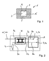
- FIG. 1 is shown in a schematic plan view of such an antenna assembly 1 in the form of a patch antenna A, for example, has two mutually offset by 90 ° feed points 3, so preferably to a through the square patch antenna A 'with their electrically conductive patch radiation surface extending diagonal are arranged symmetrically.
- a circularly polarized electromagnetic wave can be generated.
- antenna 1 is seated, for example, on a substrate, for example in the form of a printed circuit board 5.
- the circularity of the generated via the patch antenna electromagnetic wave is achieved at least by the aforementioned two feed points 3 for the two orthogonal linear polarizations.
- the required power distribution of about 50:50 and the phase difference of 90 ° can be achieved by a corresponding network N, for example, a ⁇ / 2 hybrid, as in FIG. 2 is shown schematically.
- the ⁇ / 2 hybrid shown there has two antenna ports 7a and 7b, wherein an electrical connection 8a and 8b to the two feed points 3a and 3b can be produced.
- the antenna network N is controlled via an input port 9a. Namely via a feed line 11 preferably in the form of a coaxial line 11 ', which is connected to a reader R.
- the second input port 9b that is, the fourth port of the described hybrid as a whole, is usually terminated with the characteristic impedance W of the line.
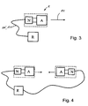
- a left circularly polarized electromagnetic wave or a right circularly polarized wave can be generated and, according to the symbolically reproduced emission direction 14 (FIG. FIG. 3 ) are radiated.
- neither polarization offers any advantage over the other polarization.
- a left or right circularly polarized wave is generated depending on the fact that the supply line 11 coming from the reader R is connected either to one or the other input port 9a or 9b and the respective other input port is terminated with the characteristic impedance mentioned.
- such a reader R with the corresponding antenna network N and the reader antenna A as in FIG. 3 shown used, in particular in automation technology.
- the reader R can also be operated with two or more spatially separated antennas A, for example, to monitor a larger predetermined range.
- the reader successively switches between the two identically polarized, spatially separated antennas A, as shown schematically in FIG FIG. 4 is shown.
- a corresponding RFID antenna system from the EP 1 845 631 A1 to be known as known.
- This antenna system is to be regarded as the closest prior art and comprises a transmission line originating from the reader and leading to the antenna network.
- the network is constructed so that it comprises a circuit arrangement for one and two downstream hybrid circuits, on the one hand, a first polarization and on the other a perpendicular second polarization can be generated in order to operate the antenna as a left-polarized or right-polarized antenna.
- control logic can be supplied as part of the antenna network, the control signals to enable the polarization switching to generate a circularly polarized electromagnetic wave at the antenna.
- a polarization switching which controls the respective reader antenna and / or operates so that the reader antenna emits alternately to produce a left and a right circularly polarized electromagnetic wave.
- the polarization direction By changing the polarization direction an improved tag recognition is realized. Irrespective of the day polarization, the most varied, ie different day forms are used.
- the invention is above all independent of the prevailing environment in the respective application.
- an antenna network upstream of the RFID antenna in which the transmission signals coming from the reader are alternately fed once on one input port and then on the other input port, about which alternately a left-handed and then a right handed circularly polarized electromagnetic wave and vice versa can be generated.
- the respectively other input port that is to say the input or port of the antenna network which is not active from the antenna network, is preferably terminated without reflection.
- a patch antenna is used which has two feed points which are alternately driven via the antenna network to produce the alternating left and right circularly polarized electromagnetic wave. In each case approx. 50% of the energy is fed in at one or the other entry point.
- the use of a patch antenna with four offset by 90 ° feed points conceivable, at each individual feed point then preferably about 25% of the transmission power is fed.
- the relevant reader is connected, for example, via two feed lines, preferably in the form of two coax lines, to the two antenna network port inputs, alternately sending the transmission signal to the one or to the other input port to transmit and produce a left or a right circular polarization on the reader antenna.
- the reader must be designed such that the respective non-active reader output is closed off from the connected coaxial line with little or no reflection.
- the antenna network is supplemented by another switching network, which is preferably also connected via a single connection line again in the form of a coaxial cable with the reader. The switching network is controlled by the reader, e.g.
- the inputs of the antenna network to the reader via an intermediate frequency superimposed on the useful signal or a DC voltage etc, the inputs of the antenna network to the reader.
- the respective non-switched input as well as above is completed without reflection.
- the mentioned antenna network and the reader antenna are preferably constructed as a unit.
- the aforementioned switching network may be separate therefrom or implemented as a common unit with the network and / or the reader antenna. If necessary, even the reader itself be constructed with the network and possibly the switching network and the reader antenna as a common unit.
- FIGS. 5 and 6 Reference is made, in which a first embodiment of the invention is shown.
- the antenna arrangement 1 in turn has an antenna A in the form of a patch antenna A 'with two feed points 3, ie, 3a and 3b.
- the antenna arrangement 1 also comprises a reference to FIGS. 1 and 2 explained n / 2 network N, which is connected via the two outputs 7a, 7b and the connecting lines 8a, 8b with the two feed points 3 in connection and this the patch antenna A 'feeds, so that thus the transmission signals coming from the reader R so are fed to the antenna A and receive the signals emitted by the tags and can be transmitted back to the reader R.
- the n / 2 network N has the aforementioned two input- or reader-side ports 9a and 9b, wherein now in deviation from the prior art two transmission or feed lines 11a and 11b are provided which lead to the reader R. It is preferably in both cases to coaxial feed lines 11 '.
- the reader R it is now possible for the reader R to be clocked in time or in succession alternately once to feed the patch antenna 1 via the one feed line 11a, wherein the other port 9b in the reader, ie the respectively non-active reader output from the antenna network is completed without reflection.
- This can be done, for example, by a (as based on FIG. 2 shown) connected to the ground resistance W, so that the line is usually terminated with the characteristic impedance of the line.
- the feed is then alternately switched by the reader so that the feed signal is no longer supplied via the first port 9a, but via the second port 9b, the network N and thus the patch antenna 1 and in this case the first line 9a is preferably completed according to the characteristic impedance of the line.
- a left-handed circularly polarized wave is radiated by the antenna, whereas when fed to the second terminal 9b a right-handed circular polarization is generated and emitted.
- the time phases for switching can be chosen arbitrarily within wide limits and adapted. A changeover, for example, in time steps of approx. 8 ms. The switching times can also be significantly longer with a high communication rate. In addition, pause times can always be provided depending on the respective switching or transmission cycles.
- an antenna arrangement 1 can be alternately operated such that alternately left circularly polarized and then right circularly polarized electromagnetic waves are alternately generated and emitted in a preselectable time interval, ie in general the relevant antenna A and in particular the patch antenna A 'is operated alternately as a left-handed circularly polarized antenna and then as a right-handed circularly polarized antenna.
- FIG. 6 For example, it is indicated that two pairs of feed line 11, 11 'emanate via a reader to two antennas A, in each case via the mentioned network N.
- An arrangement according to FIG. 6 is particularly suitable for monitoring a passage area D, which is arranged between the two antenna assemblies A. It can in accordance with the arrangement FIG. 6 from the reader R, respectively, the antenna arrangement lying on the left from the passage region D and, subsequently, the antenna arrangement on the right thereof are actuated and operated, which are then operated alternately left and right circularly.
- the described antenna arrangement 1 and the operation including the reader R are suitable for different frequency ranges. Particularly suitable and determined is the antenna structure and the use of a corresponding reader for the UHF range, ie a frequency range of 800 MHz to 1 GHz, in particular for the 865 MHz to 868 MHz range or the 902 MHz to 928 MHz range.
- the reader R can be integrated together with the patch antenna A, that is, with the one patch antenna 1 and the feed network N in a housing 25.
- the reader R can be integrated together with the patch antenna A, that is, with the one patch antenna 1 and the feed network N in a housing 25.
- a left and a right circularly polarized electromagnetic wave can be generated.
- FIGS. 5 and 6 Based on FIG. 8 is opposed to a different embodiment FIGS. 5 and 6 insofar shown, as the actual network yet another switching network U is connected upstream. Further, each of the antenna assemblies A to the network N and the upstream switching network U via only one line 11, in particular only a coaxial line 11 ', driven and fed.
- This upstream switching network U thus has only one reader-side connection port 21 and only one connection, preferably in the form of a coaxial cable 11 ', via this cable 11' not only the corresponding feed signal but also, for example, a useful signal superimposed intermediate frequency or a DC voltage is supplied as a further signal, which allows the switching network, a corresponding switching from its input 21 to one of the two outputs 19a and 19b and thus via the in FIG.
- the switching network is housed in the common housing 25, wherein the reader is provided separately in the illustrated embodiment, but need not be separated.
- the switching network could also be provided outside the housing 25 separate from the actual network N and the patch antenna 1.
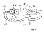
- FIG. 9 Now, a final embodiment is shown, in which an antenna, for example a patch antenna with four feed points is used.
- the network N has four antenna-side ports 9a, 9b, 9c and 9d.
- the feed takes place at each individual feed point with about 25% of the transmission power.
- antennas can be used which have at least two feed points, so that both circular polarizations (right and left rotation) can be achieved.
- patch antennas, cross dipoles, slot antennas, loop antennas, etc. come into consideration for the antennas.
- the antenna should not only operate or operate in a left-hand and right-hand circularly polarizing manner, but that the antenna should generally produce a corresponding left- or right-handed rotating elliptical polarization.
- Circular polarizations represent only a special case of elliptical polarization.
Landscapes
- Engineering & Computer Science (AREA)
- Physics & Mathematics (AREA)
- Toxicology (AREA)
- Health & Medical Sciences (AREA)
- Theoretical Computer Science (AREA)
- Artificial Intelligence (AREA)
- Computer Vision & Pattern Recognition (AREA)
- General Physics & Mathematics (AREA)
- General Health & Medical Sciences (AREA)
- Electromagnetism (AREA)
- Computer Networks & Wireless Communication (AREA)
- Variable-Direction Aerials And Aerial Arrays (AREA)
- Waveguide Aerials (AREA)
Description
Die Erfindung betrifft ein Verfahren zur Ansteuerung einer RFID-Antenne sowie ein zugehöriges RFID-Antennen-System nach dem Oberbegriff des nebengeordneten Anspruchs.The invention relates to a method for controlling an RFID antenna and an associated RFID antenna system according to the preamble of the independent claim.
Ein RFID-Antennen-System ist beispielsweise aus der
RFID-Verfahren zur kontaktlosen Identifikation von auf sogenannten RFID-Tags gespeicherten Informationen mittels magnetischer, elektrischer und/oder elektromagnetischer Energie- und Datenübertragung sind hinlänglich bekannt. Bei dem RFID-Verfahren (Radiofrequenz-Identifizierung) handelt es sich um eine Möglichkeit, auf tragbaren Datenträgern befindliche Informationen kontaktlos auszulesen und/oder Informationen auf dem tragbaren Datenträger zu schreiben. Zum Einsatz kommen sogenannte passive RFID-Tags, die ihre Energie immer aus dem elektrischen, magnetischen und/oder elektromagnetischen Feld einer Antenne erhalten, oder sogenannte aktive RFID-Tags, die mit einer eigenen (aufladbaren) Energieversorgung versehen sind. Allgemein handelt es sich bei den RFID-Tags um sogenannte Transponder.RFID methods for the contactless identification of information stored on so-called RFID tags by means of magnetic, electrical and / or electromagnetic energy and data transmission are well known. The RFID method (Radio Frequency Identification) is a way to contactlessly read information on portable data carriers and / or to write information on the portable data carrier. Are used so-called passive RFID tags that always get their energy from the electrical, magnetic and / or electromagnetic field of an antenna, or so-called active RFID tags that with a own (rechargeable) power supply are provided. In general, the RFID tags are so-called transponders.
Die in Rede stehenden RFID-Tags können für die unterschiedlichsten Einsatzzwecke verwendet werden, nämlich zur Erfassung (Detektion, Identifikation) von Gegenständen und /oder Produkten unterschiedlichster Art, beispielsweise zur Identifikation und Erfassung von Kleidungsstücken, beispielsweise T-Shirts etc.The RFID tags in question can be used for a wide variety of purposes, namely for the detection (detection, identification) of objects and / or products of various kinds, for example for the identification and detection of garments, such as T-shirts, etc.
Bekanntermaßen werden RFID-Tags und die zugehörigen Identifikationsverfahren so aufgebaut und umgesetzt, dass ein Schreib- und/oder Lesegerät (ein sogenannter Reader) vorgesehen ist. Der Reader ist an einer Antenne angeschlossen, worüber die entsprechenden Abfragesignale ausgesandt bzw. die entsprechenden Informations-Antworten von Tags erhalten werden können. Beim RFID-Verfahren wird dabei häufig auf der gleichen Frequenz ausgesendet und empfangen (es kann allerdings auch auf unterschiedlichen Frequenzen gesendet und empfangen werden). Das von der Antenne des Schreib- und/oder Lesegerätes ausgesandte Signal kann gleichzeitig zur Energieversorgung der Tags dienen. Die entsprechenden Informationen werden aus dem Tag ausgelesen und an das Sende- und/oder Empfangsgerät zurückgesandt, das über eine zugeordnete Antenne das entsprechende Signal auffangen und auswerten kann. Es handelt sich also um einen bidirektionalen Sende-Empfangsweg in einem gleichen Frequenzbereich oder Frequenzband. Dazu sind in den unterschiedlichen Ländern gegebenenfalls unterschiedliche Frequenzbänder für diese Technik freigegeben.As is known, RFID tags and the associated identification methods are constructed and implemented in such a way that a writing and / or reading device (a so-called reader) is provided. The reader is connected to an antenna via which the corresponding interrogation signals can be sent out or the corresponding information responses of tags can be obtained. The RFID method is often transmitted and received at the same frequency (but it can also be transmitted and received on different frequencies). The signal emitted by the antenna of the writing and / or reading device can simultaneously serve to supply the energy for the tags. The corresponding information is read from the tag and sent back to the transmitting and / or receiving device, which can capture and evaluate the corresponding signal via an associated antenna. It is therefore a bidirectional transmission-reception path in a same frequency range or frequency band. For this purpose, different frequency bands may be released for this technique in the different countries.
Grundsätzlich besteht bei RFID-Systemen das Problem, alle in einem Antennen-Bereich befindlichen Tags vollständig und richtig auszulesen. Problematisch ist dabei insbesondere, dass eventuell eine Vielzahl von Produkten, die mit Tags versehen sind, auf engem Raum hintereinander und/oder nebeneinander zu liegen kommen, so dass unter Umständen bestimmte Tags nicht richtig oder nicht vollständig oder überhaupt nicht ausgelesen werden können.Basically there is the problem with RFID systems, all completely and correctly read tags located in an antenna area. The problem in particular is that possibly a large number of products that are tagged, come in a small space behind each other and / or next to each other, so that certain tags may not be read correctly or not completely or not at all.
Dabei ist bekannt, dass die Leserate durch Verstärkung des Antennensignals verbessert werden kann. Allerdings bestehen normative Beschränkungen der Reader-Sendeleistungen. Da diese normative Beschränkung der Reader-Sendeleistung jedoch auf die linearen Feldkomponenten der Antenne bezogen sind, werden bevorzugt zirkular polarisierte Antennen für die Reader eingesetzt, um Tags trotz ihrer überwiegend linearen Polarisation in verschiedenen Ausrichtungen besser ansprechen zu können und um die zirkular polarisierte Antenne letztlich mit höherer Gesamtleistung (beispielsweise maximal 3 dB) betreiben zu können, verglichen mit einer linear polarisierten RFID-Antenne. Aufgrund der undefinierten Umgebung und Tag-Anordnung kann allerdings das Ansprechen der Tags richtungsabhängig stark beeinflusst werden.It is known that the read rate can be improved by amplifying the antenna signal. However, there are normative limitations of reader transmission power. However, since this normative limitation of the reader transmit power is related to the linear field components of the antenna, it is preferred to use circularly polarized antennas for the readers to better address tags despite their predominantly linear polarization in different orientations and ultimately around the circularly polarized antenna higher total power (for example, a maximum of 3 dB) to operate compared to a linearly polarized RFID antenna. Due to the undefined environment and tag arrangement, however, the response of the tags can be strongly influenced depending on the direction.
Üblicherweise werden als Reader-Antenne überwiegend zirkular polarisierte Antennen eingesetzt. In
Ein derartiger Stand der Technik ist beispielsweise aus der
Durch eine derartige Antenne kann entweder eine linkszirkular polarisierte elektromagnetische Welle oder rechtszirkular polarisierte Welle erzeugt und gemäß symbolisch wiedergegebener Abstrahlrichtung 14 (
Grundsätzlich ist aber auch ein entsprechendes RFID-Antennen-System aus der
Über eine zusätzliche separate Steuerleitung können der Steuerungs-Logik als Teil des Antennen-Netzwerkes die Steuersignale zugeführt werden, um darüber die Polarisationsumschaltung zur Erzeugung einer zirkularpolarisierten elektromagnetischenwelle an der Antenne zu ermöglichen.Via an additional separate control line, the control logic can be supplied as part of the antenna network, the control signals to enable the polarization switching to generate a circularly polarized electromagnetic wave at the antenna.
Der hierfür notwendige Aufwand ist allerdings nicht zu unterschätzen.However, the necessary effort is not to be underestimated.
Aufgabe der vorliegenden Erfindung ist es demgegenüber, ausgehend von einem derartigen grundsätzlich nach dem Stand der Technik bekannten System ein verbessertes Verfahren sowie eine verbesserte Vorrichtung zur kontaktlosen Übertragung von Daten von und/oder zu einer Vielzahl von Daten- und/oder Informationsträgern vorzugsweise in Form von RFID-Tags zu schaffen.On the other hand, it is an object of the present invention, on the basis of such a system known in principle according to the prior art, to provide an improved method and apparatus for the contactless transmission of data from and / or to a multiplicity of data and / or information carriers, preferably in the form of To create RFID tags.
Die Aufgabe wird bezüglich des Verfahrens entsprechend den in Anspruch 1 und bezüglich des RFID-Antennen-Systems bezüglich den im Anspruch 10 angegebenen Merkmalen gelöst. Vorteilhafte Ausgestaltungen der Erfindung sind in den Unteransprüchen angegeben.The object is achieved with respect to the method according to the
Es muss als ausgesprochen überraschend bezeichnet werden, dass ohne großen technischen Aufwand gegenüber herkömmlichen Verfahren und RFID-Antennen-Systemen eine deutliche Verbesserung erzielbar ist. Überraschend ist dabei auch, dass durch die erfindungsgemäße Lösung weder der technische Aufwand überproportional ansteigt, noch erforderliche Komponenten einen zusätzlichen Bauraum benötigen.It must be described as extremely surprising that a significant improvement can be achieved without great technical effort compared to conventional methods and RFID antenna systems. It is also surprising that neither the technical complexity increases disproportionately by the inventive solution, nor required components require additional space.
Erfindungsgemäß ist nämlich eine Polarisations-Umschaltung vorgesehen, die die betreffende Reader-Antenne so ansteuert und/oder betreibt, dass die Reader-Antenne wechselweise unter Erzeugung einer links- sowie einer rechtszirkular polarisierten elektromagnetischen Welle abstrahlt. Durch den Wechsel der Polarisationsrichtung wird eine verbesserte Tag-Erkennung realisiert. Dabei können unabhängig von der Tag-Polarisation unterschiedlichste, d.h. verschiedenste Tagformen eingesetzt werden. Die Erfindung ist dabei vor allem auch von der im jeweiligen Einsatzbereich vorherrschenden Umgebung unabhängig.Namely, according to the invention, a polarization switching is provided, which controls the respective reader antenna and / or operates so that the reader antenna emits alternately to produce a left and a right circularly polarized electromagnetic wave. By changing the polarization direction an improved tag recognition is realized. Irrespective of the day polarization, the most varied, ie different day forms are used. The invention is above all independent of the prevailing environment in the respective application.
Die erfindungsgemäße Lösung zeichnet sich vor allem durch die Einfachheit ihrer Konstruktion und Umsetzung aus. Denn im Stand der Technik ist bisher nur vorgesehen, dass eine zirkularpolarisierte elektromagnetische Welle durch die Antenne erzeugt wird, entweder nur rechts- oder linkszirkulierend, also nicht wechselweise sich ändernd, oder aber es ist eine vergleichweise aufwändige Polarisations-Umschaltungs-Einrichtung vorgesehen, beispielsweise in der
In einer bevorzugten Ausführungsform der Erfindung wird dabei ein der RFID-Antenne vorgeschaltetes Antennen-Netzwerk verwendet, bei welchem die vom Reader kommenden Sendesignale wechselweise einmal auf dem einen Eingangs-Port und dann auf dem anderen Eingangs-Port eingespeist werden, worüber wechselweise eine linkshändige und dann eine rechtshändige zirkular polarisierte elektromagnetische Welle und umgekehrt erzeugt werden kann. Bevorzugt wird dabei der jeweils andere Eingangs-Port, also der vom Antennennetzwerk aus gesehen nicht aktive Eingang oder Port des Antennennetzes, reflexionsfrei abgeschlossen. Bevorzugt wird eine Patch-Antenne verwendet, die zwei Einspeisepunkte aufweist, die wechselweise über das Antennen-Netzwerk angesteuert werden, um die wechselweise links- und rechtszirkular polarisierte elektromagnetische Welle zu erzeugen. Hierbei wird jeweils ca. 50% der Energie am einen bzw. am anderen Einspeisepunkt eingespeist. Ebenso wäre beispielsweise die Verwendung einer Patch-Antenne mit vier um 90° versetzt liegenden Speisepunkten denkbar, wobei an jedem einzelnen Speisepunkt dann bevorzugt ca. 25% der Sendeleistung eingespeist wird.In a preferred embodiment of the invention, an antenna network upstream of the RFID antenna is used, in which the transmission signals coming from the reader are alternately fed once on one input port and then on the other input port, about which alternately a left-handed and then a right handed circularly polarized electromagnetic wave and vice versa can be generated. In this case, the respectively other input port, that is to say the input or port of the antenna network which is not active from the antenna network, is preferably terminated without reflection. Preferably, a patch antenna is used which has two feed points which are alternately driven via the antenna network to produce the alternating left and right circularly polarized electromagnetic wave. In each case approx. 50% of the energy is fed in at one or the other entry point. Likewise, for example, the use of a patch antenna with four offset by 90 ° feed points conceivable, at each individual feed point then preferably about 25% of the transmission power is fed.
Aus der erläuterten Schilderung ergibt sich, dass der betreffende Reader beispielsweise über zwei Speiseleitungen bevorzugt in Form von zwei Koaxleitungen mit den beiden Antennen-Netzwerk-Port-Eingängen verbunden ist, um dabei wechselweise das Sendesignal an den einen bzw. an den anderen Eingangs-Port zu übermitteln und eine links- bzw. eine rechtszirkular Polarisation an der Reader-Antenne zu erzeugen. Der Reader muss dabei erfindungsgemäß so ausgeführt werden, dass der jeweils nicht aktive Reader-ausgang von der angeschlossenen Koaxialleitung aus gesehen reflexionsarm bzw. bevorzugt reflexionsfrei abgeschlossen ist. Möglich ist aber auch, dass das Antennen-Netzwerk um ein weiteres Umschalt-Netzwerk ergänzt wird, welches lediglich über eine einzige Verbindungsleitung vorzugsweise ebenfalls wieder in Form eines Koaxialkabels mit dem Reader verbunden ist. Das Umschalt-Netzwerk schaltet dabei durch den Reader gesteuert z.B. über eine dem Nutzsignal überlagerte Zwischenfrequenz oder eine Gleichspannung etc, die Eingänge des Antennen-Netzwerkes zum Reader durch. Gleichzeitig wird der jeweils nicht durchgeschaltete Eingang wie auch oben reflexionsfrei abgeschlossen. In diesem Fall wird an die Impedanz des jeweils nicht aktiven Readerausgangs - sofern mehrere vorhanden sind - keine spezielle Anforderung gestellt.From the described description it follows that the relevant reader is connected, for example, via two feed lines, preferably in the form of two coax lines, to the two antenna network port inputs, alternately sending the transmission signal to the one or to the other input port to transmit and produce a left or a right circular polarization on the reader antenna. According to the invention, the reader must be designed such that the respective non-active reader output is closed off from the connected coaxial line with little or no reflection. It is also possible that the antenna network is supplemented by another switching network, which is preferably also connected via a single connection line again in the form of a coaxial cable with the reader. The switching network is controlled by the reader, e.g. via an intermediate frequency superimposed on the useful signal or a DC voltage etc, the inputs of the antenna network to the reader. At the same time, the respective non-switched input as well as above is completed without reflection. In this case, the impedance of the respective non-active reader output - if there are several - no special requirement.
Das erwähnte Antennen-Netzwerk und die Reader-Antenne sind bevorzugt als Einheit aufgebaut. Das vorstehend erwähnte Umschalt-Netzwerk kann davon getrennt oder als gemeinsame Baueinheit mit dem Netzwerk und/oder der Reader-Antenne ausgeführt sein. Bei Bedarf kann sogar der Reader selbst mit dem Netzwerk und gegebenenfalls dem Umschalt-Netzwerk und der Reader-Antenne als gemeinsame Baueinheit aufgebaut sein.The mentioned antenna network and the reader antenna are preferably constructed as a unit. The aforementioned switching network may be separate therefrom or implemented as a common unit with the network and / or the reader antenna. If necessary, even the reader itself be constructed with the network and possibly the switching network and the reader antenna as a common unit.
Die Erfindung wird nachfolgend anhand von Zeichnungen weiter erläutert. Dabei zeigen im einzelnen
- Figur 1:
- eine schematische Draufsicht auf eine nach dem Stand der Technik bekannte Patch-Antennemit zwei Einspeisepunkten;
- Figur 2:
- eine nach dem Stand der Technik bekannte Schaltungsanordnung mit einer Reader-Antenne,die über ein Antennen-Netzwerk in Form eines π/2-Hybrides zur Erzeugung einerzirkular polarisierten elektromagnetischenWelle angesteuert wird;
- Figur 3:
- eine entsprechende Ansteuerung der in Figur2 dargestellten Schaltungsanordnung, ausgehend von einem Reader über eine Koaxialleitung,nach dem Stand der Technik;
- Figur 4:
- eine zu
Figur 3 erweiterte Schaltungsanordnungnach dem Stand der Technik, bei der vom einen Reader aus zwei Reader-Antennenmit dem jeweils vorgeschalteten Antennen-Netzwerk angesteuert werden; - Figur 5:
- eine erfindungsgemäße Schaltungsanordnung einer Reader-Antenne mit einem vorgeschaltetenAntennen-Netzwerk;
- Figur 6:
- ein erfindungsgemäßes RFID-Antennen-System;
- Figur 7:
- ein zu
Figur 6 abgewandeltes Ausführungsbeispiel,bei welchem die Reader-Antenne, ein Netzwerk und der Reader selbst als gemeinsame Baueinheit ausgebildet sind; - Figur 8:
- ein zu
Figur 6 nochmals abgewandeltes erfindungsgemäßesAusführungsbeispiel; und - Figur 9:
- ein zu
Figur.6 nochmals abgewandeltes Ausführungsbeispielmit einer Antenne in Form einer Patch-Antenne, die über vier Speisepunktegespeist wird.
- FIG. 1:
- a schematic plan view of a known in the art patch antenna with two feed points;
- FIG. 2:
- a known prior art circuit arrangement with a reader antenna which is driven via an antenna network in the form of a π / 2 hybrid to produce a circularly polarized electromagnetic wave;
- FIG. 3:
- a corresponding control of the circuit arrangement shown in Figure 2, starting from a reader via a coaxial line, according to the prior art;
- FIG. 4:
- one too
FIG. 3 extended circuit arrangement according to the prior art, in which are controlled by one reader of two reader antennas with the respective upstream antenna network; - FIG. 5:
- a circuit arrangement according to the invention of a reader antenna with an upstream antenna network;
- FIG. 6:
- an inventive RFID antenna system;
- FIG. 7:
- one too
FIG. 6 modified embodiment in which the reader antenna, a network and the reader itself are designed as a common unit; - FIG. 8:
- one too
FIG. 6 another modified embodiment of the invention; and - FIG. 9:
- one too
Figur.6 again modified embodiment with an antenna in the form of a patch antenna, which is fed via four feed points.
Nachfolgend wird auf die
Erfindungsgemäß weist die Antennenanordnung 1 wiederum eine Antenne A in Form einer Patch-Antenne A' mit zwei Speisepunkten 3, d.h. 3a und 3b auf. Die Antennenanordnung 1 umfasst neben der Antenne A zudem ein anhand von
Das n/2-Netzwerk N weist die erwähnten beiden eingangs- oder readerseiteigen Ports 9a und 9b auf, wobei nunmehr in Abweichung zum Stand der Technik zwei Übertragungs- oder Speiseleitungen 11a und 11b vorgesehen sind, die zum Reader R führen. Es handelt sich bevorzugt in beiden Fällen um koaxiale Speiseleitungen 11'.The n / 2 network N has the aforementioned two input- or reader-side ports 9a and 9b, wherein now in deviation from the prior art two transmission or feed lines 11a and 11b are provided which lead to the reader R. It is preferably in both cases to coaxial feed lines 11 '.
Durch diesen Aufbau ist es nunmehr möglich, dass vom Reader R zeitgetaktet oder unmittelbar aufeinander folgend wechselweise einmal eine Anspeisung der Patch-Antenne 1 über die eine Speiseleitung 11a erfolgt, wobei im Reader der jeweils andere Port 9b, also der jeweils nicht aktive Reader-Ausgang vom Antennen-Netzwerk aus gesehen reflexionsfrei abgeschlossen wird. Dies kann beispielsweise durch einen (wie anhand von
Beispielsweise in einem Zeitmultiplex-Verfahren wird dann vom Reader die Einspeisung wechselweise so umgeschaltet, dass das Einspeisesignal nicht mehr über den ersten Port 9a, sondern über den zweiten Port 9b, dem Netzwerk N und damit der Patch-Antenne 1 zugeführt und in diesem Fall dann die erste Leitung 9a bevorzugt entsprechend dem Wellenwiderstand der Leitung abgeschlossen wird.For example, in a time division multiplex method, the feed is then alternately switched by the reader so that the feed signal is no longer supplied via the first port 9a, but via the second port 9b, the network N and thus the
Bei Speisung des ersten Anschlusses 9a wird dabei beispielsweise ein linkshändige zirkular polarisierte Welle von der Antenne abgestrahlt, wohingegen bei Speisung am zweiten Anschluss 9b eine rechtshändig zirkulare Polarisation erzeugt und abgestrahlt wird. Die Zeitphasen für die Umschaltung kann dabei in weiten Grenzen beliebig gewählt und angepasst werden. Eine Umschaltung beispielsweise in Zeitschritten von ca. 8 ms. Die Umschaltzeiten können aber bei hoher Kommunikationsrate auch deutlich länger sein. Zudem können Pausezeiten je nach den jeweiligen Umschalte- oder Sendezyklen grundsätzlich vorgesehen sein.When feeding the first terminal 9a, for example, a left-handed circularly polarized wave is radiated by the antenna, whereas when fed to the second terminal 9b a right-handed circular polarization is generated and emitted. The time phases for switching can be chosen arbitrarily within wide limits and adapted. A changeover, for example, in time steps of approx. 8 ms. The switching times can also be significantly longer with a high communication rate. In addition, pause times can always be provided depending on the respective switching or transmission cycles.
Bei einem derartigen Aufbau mit einem Reader, von dem zwei Speiseleitungen ausgehen, kann beispielsweise eine Antennenanordnung 1 wechselweise so betrieben werden, dass aufeinander folgend in einem vorwählbaren zeitlichen Abstand abwechselnd links zirkular polarisierte und dann rechts zirkular polarisierte elektromagnetische Wellen erzeugt und abgestrahlt werden, also allgemein die betreffende Antenne A und insbesondere die Patch-Antenne A' wechselweise als linkshändig zirkular polarisierte Antenne und dann als rechtshändig zirkular polarisierte Antenne betrieben wird. Bei dem Ausführungsbeispiel gemäß
Ferner ist darauf zu achten, dass die Übergänge vom Antennen-Netzwerk N, also von der Antennenanordnung 1 auf die Koaxialkabel 11' und von den Kabeln 11' auf den Reader R reflexionsfrei bzw. äußerst reflexionsarm gestaltet sind.It should also be ensured that the transitions from the antenna network N, ie from the
Die beschriebende Antennenanordnung 1 und der Betrieb einschließlich des Readers R eignen sich für unterschiedliche Frequenzbereiche. Besonders geeignet und bestimmt ist der Antennenaufbau und die Verwendung eines entsprechenden Readers für den UHF-Bereich, also ein Frequenzbereich von 800 MHz bis 1 GHz insbesondere für den 865 MHz bis 868 MHz-Bereich oder den 902 MHz bis 928 MHz-Bereich.The described
Ziel bei derartigen UHF-RFID-Systemen ist die Erzielung einer möglichst hohen Leserate (Tagerkennung) bei unterschiedlichster Umgebung und Tag-Anordnung, wobei die Mehrzahl der verfügbaren Tags in der Regel überwiegend lineare Polarisation besitzen.The aim of such UHF RFID systems is to achieve the highest possible read rate (tag recognition) in a wide variety of environments and tag arrangement, the majority of available tags usually have predominantly linear polarization.
Anhand von
Anhand von
Im gezeigten Ausführungsbeispiel ist auch das Umschalt-Netzwerk in dem gemeinsamen Gehäuse 25 untergebracht, wobei im gezeigten Ausführungsbeispiel der Reader davon getrennt vorgesehen ist, aber nicht getrennt sein muss. Das Umschalt-Netzwerk könnte auch außerhalb des Gehäuses 25 von dem eigentlichen Netzwerk N und der Patch-Antenne 1 getrennt vorgesehen sein.In the illustrated embodiment, the switching network is housed in the
In
Bezug nehmend auf alle Ausführungsbeispiele soll ferner angemerkt werden, dass generell alle Antennen verwendet werden können, die über mindestens zwei Speisepunkte verfügen, so dass beide zirkulare Polarisationen (rechts- und linksdrehend) erzielt werden können. Somit kommen also erfindungsgemäß für die Antennen beispielsweise Patch-Antennen, Kreuzdipole, Schlitzantennen, Loopantennen etc. in Betracht.With reference to all embodiments, it should further be noted that generally all antennas can be used which have at least two feed points, so that both circular polarizations (right and left rotation) can be achieved. Thus, according to the invention, for example, patch antennas, cross dipoles, slot antennas, loop antennas, etc. come into consideration for the antennas.
Ferner wird angemerkt, dass die Antenne nicht nur links- und rechtszirkular polarisierend arbeiten oder betrieben werden soll, sondern dass die Antenne allgemein eine entsprechende links- oder rechtsdrehende elliptische Polarisation erzeugen sollte.It is further noted that the antenna should not only operate or operate in a left-hand and right-hand circularly polarizing manner, but that the antenna should generally produce a corresponding left- or right-handed rotating elliptical polarization.
Zirkulare Polarisationen stellen insoweit nur einen Sonderfall der elliptischen Polarisation dar.Circular polarizations represent only a special case of elliptical polarization.
Claims (18)
- Method for activating an RFID antenna having the following features:- an antenna (A) and an antenna network (N) are used, wherein the antenna (A) is operated via the antenna network (N) by means of a connectable reader (R),- the antenna (A) is operated as a circular or elliptical polarized antenna (A) in such a way that it is alternately left-handed and right-handed polarized;- an antenna network (N) comprising two reader-side ports (9a, 9b) is used, one reader-side port (9a or 9b) being connected to the reader via a line (11, 11') and the other reader-side port (9b or 9a) being closed with little reflection and preferably no reflection when viewed from the antenna network (N),characterized by the following further features:- a π/2 hybrid network is used as an antenna network,- a transmitted and useful signal coming from the connectable reader (R) is alternately fed first to one reader-side port (9a or 9b) and then to the other reader-side port (9b or 9a) of the antenna network (N) so as to alternately produce left-handed and right-handed polarization,- and the respective inactive reader-side port (9b or 9a) is alternately closed with little reflection and preferably no reflection when viewed from the antenna network (N).
- Method according to claim 1, characterized in that the antenna network (N) and the two reader-side ports (9a, 9b) associated therewith are separately activated by two lines (11, 11') coming from the reader (R), the transmitted and useful signals coming from the reader (R) being alternately fed first to one reader-side port (9a) and then to the other reader-side port (9b), via which a left-handed and then a right-handed circular polarized electromagnetic wave are produced alternately at the antenna (A), the other respective reader-side port (9b or 9a) being closed in the reader (R) with little reflection and preferably no reflection when viewed from the network (N).
- Method according to claim 1, characterized in that a switching network (U) is also used which is connected upstream of the antenna network (N), the switching network (U) being activated by a line (11, 11') from the reader (R) in such a way that a transmitted and useful signal coming from the reader (R) is alternately fed first to one reader-side port (9a) via one output (19a) of the switching network (U) and then to the other reader-side port (9b) of the antenna network (N) via the other output (19b) of the switching network (U),the respective reader-side port (9b or 9a) which has not been connected through preferably being closed in the switching network (U) with little reflection or no reflection when viewed from the network (N).
- Method according to claim 3, characterized in that, in addition to a transmitted and useful signal, a signal in the form of a superposed intermediate frequency or a d.c. voltage is fed to the reader-controlled switching network (U) via the reader-side port (21) thereof, as a function of which signal the transmitted and useful signal is fed in a different manner to one of the reader-side ports (9a, 9b) of the antenna network (N) arranged downstream, the connected antenna (A) emitting in an alternately left-handed and right-handed circular polarized manner as a function thereof.
- Method according to any one of claims 1 to 4, characterized in that the successive left-handed and right-handed polarization states follow one another directly or are preferably produced alternately at a pre-determined time interval.
- Method according to any one of claims 1 to 5, characterized in that a patch antenna (A') is used, of which feeding points (3; 3a, 3b, 3c, 3d) are activated alternately in such a way that left-handed and right-handed polarization are produced alternately at the patch antenna (A').
- Method according to claim 6, characterized in that a patch antenna (A') comprising two feeding points (3; 3a, 3b) is used, approximately 50 % of the transmitting power preferably being fed to each of said points.
- Method according to claim 6, characterized in that a patch antenna (A') having four feeding points (3; 3a, 3b, 3c, 3d) is used, approximately 25 % of the transmitting power preferably being fed to each of said points.
- Method according to any one of claims 1 to 98 characterized in that the antenna (A) is used as an RFID antenna (A) in a UHF-frequency range, in particular in a frequency range of from 800 MHz to 1 GHz, in particular of from 865 MHz to 868 MHz or in particular from 902 MHz to 928 MHz.
- RFID antenna system having the following features:- a circular polarized antenna (A)- an antenna network (N) for controlling and/or operating the antenna (A),- the antenna network (N) comprises at least two antenna-side ports (7a, 7b, 7c, 7d) for feeding the antenna (A), left-handed or right-handed polarization being able to be produced by means of the antenna (A),- the antenna network (N) comprises two reader-side ports (9a, 9b), one port (9a or 9b) being able to be connected or being connected via a line (11, 11') to a reader (R) and the respective second port (9b or 9a) being closed with little reflection or no reflection,characterized by the following further features:- the antenna network (N) consists of a π/2 hybrid network,- the antenna network (N) is configured in such a way that a transmitted and useful signal coming from the connectable reader (R) can be alternately fed first to one reader-side port (9a, 9b) and then to the other reader-side port (9a, 9b) of the antenna network (N) so as to alternately produce left-handed and right-handed polarization, and- the antenna network (N) is configured in such a way that the respective inactive reader-side port (9b or 9a) is alternately closed with little reflection and preferably no reflection when viewed from the antenna network (N).
- RFID antenna system according to claim 10, characterized in that the antenna network (N) and the two reader-side ports (9a, 9b) associated therewith can be separately activated by two lines (11, 11') coming from the reader (R), the transmitted and useful signals coming from the reader (R) being alternately fed first to one reader-side port (9a) and then to the other reader-side port (9b), via which a left-handed and then a right-handed circular polarized electromagnetic wave can be produced alternately at the antenna (A).
- RFID antenna system according to claim 10, characterized in that a switching network (U) is also provided which is connected upstream of the antenna network (N), the switching network (U) being able to be activated by a line from the reader (R) in such a way that a transmitted and useful signal coming from the reader (R) is alternately fed first to one reader-side port (9a) via one output (19a) of the switching network (U) and then to the other reader-side port (9b) of the antenna network (N) via the other output (19b) of the switching network (U), the respective reader-side port (9b or 9a) which has not been connected through preferably being closed in the switching network (U) with little reflection or no reflection when viewed from the network (N).
- RFID antenna system according to claim 12, characterized in that, in addition to a transmitted and useful signal, a signal in the form of a superposed intermediate frequency or a d.c. voltage can be fed to the reader-controlled switching network (U) via the one reader-side port (21) thereof, as a function of which signal the transmitted and useful signal may be fed in a different manner to one of the reader-side ports (9a, 9b) of the antenna network (N) arranged downstream, as a function of which the connected antenna (A) can be in turn operated as a left-handed polarized or right-handed polarized antenna (A).
- RFID antenna system according to any one of claims 10 to 13, characterized in that the antenna (A) can be activated via the antenna network (N) in a preferably reader-controlled manner in such a way that left-circular and right-circular polarization can be produced alternately so as to either follow one another directly or at a pre-determined time interval.
- RFID antenna system according to any one of claims 10 to 14, characterized in that the antenna (A) consists of an antenna (A) or comprises an antenna which in turn comprises at least two feeding points (3; 3a, 3b) the antenna (A) preferably consisting of a patch antenna (A'), a turnstile aerial, a slot aerial or a loop antenna.
- RFID antenna according to claim 15, characterized in that the antenna (A) comprises two feeding points (3; 3a, 3b), at least approximately 50 % of the transmitting power being able to be fed to each of said points.
- RFID antenna according to claim 15, characterized in that the antenna (A) comprises four feeding points (3; 3a, 3b, 3c, 3d), approximately 25 % of the transmitting power preferably being able to be fed to each of said points.
- RFID antenna system according to any one of claims 10 to 17, characterized in that the antenna (A) is provided as an RFID-antenna (A) for use within a UHF-frequency range, in particular within a frequency range of from 800 MHz to 1 GHz, in particular of from 865 MHz to 868 MHz or from 902 MHz to 928 MHz.
Applications Claiming Priority (2)
| Application Number | Priority Date | Filing Date | Title |
|---|---|---|---|
| DE102008063787 | 2008-12-18 | ||
| PCT/EP2009/007933 WO2010069433A1 (en) | 2008-12-18 | 2009-11-05 | Method for actuating an rfid antenna, and an associated rfid antenna system |
Publications (2)
| Publication Number | Publication Date |
|---|---|
| EP2368210A1 EP2368210A1 (en) | 2011-09-28 |
| EP2368210B1 true EP2368210B1 (en) | 2012-12-26 |
Family
ID=41478509
Family Applications (1)
| Application Number | Title | Priority Date | Filing Date |
|---|---|---|---|
| EP09752742A Active EP2368210B1 (en) | 2008-12-18 | 2009-11-05 | Method for actuating an rfid antenna, and an associated rfid antenna system |
Country Status (2)
| Country | Link |
|---|---|
| EP (1) | EP2368210B1 (en) |
| WO (1) | WO2010069433A1 (en) |
Families Citing this family (4)
| Publication number | Priority date | Publication date | Assignee | Title |
|---|---|---|---|---|
| DE102012009290B4 (en) | 2012-05-11 | 2014-12-11 | KATHREIN Sachsen GmbH | Circularly polarized UHF RFlD antenna |
| DE202013104222U1 (en) | 2013-09-16 | 2013-10-21 | ASTRA Gesellschaft für Asset Management mbH & Co. KG | RFID reader |
| DE102016014589B4 (en) | 2016-12-05 | 2018-10-04 | KATHREIN Sachsen GmbH | antenna array |
| CN106911007B (en) * | 2017-03-16 | 2019-04-23 | 西安电子科技大学 | Multi-layer metamaterial surface texture for multi-band frequency selection wave transparent angle |
Family Cites Families (4)
| Publication number | Priority date | Publication date | Assignee | Title |
|---|---|---|---|---|
| CN101112008B (en) | 2005-01-31 | 2011-08-17 | 富士通株式会社 | Radio frequency recognizing communication control method and radio frequency recognition system using the same |
| US7551140B2 (en) | 2005-11-03 | 2009-06-23 | Symbol Technologies, Inc. | Low return loss rugged RFID antenna |
| DE202006017474U1 (en) * | 2006-09-01 | 2007-03-01 | Wilhelm Sihn Jr. Gmbh & Co. Kg | Reading device for radio frequency identification system, has antenna module with antennas, where one of antennas has two liner polarization directions, and switching device switching one of antennas between directions and/or planes |
| DE102007018059A1 (en) | 2007-04-17 | 2008-10-23 | Kathrein-Werke Kg | RFID antenna system |
-
2009
- 2009-11-05 EP EP09752742A patent/EP2368210B1/en active Active
- 2009-11-05 WO PCT/EP2009/007933 patent/WO2010069433A1/en active Application Filing
Also Published As
| Publication number | Publication date |
|---|---|
| EP2368210A1 (en) | 2011-09-28 |
| WO2010069433A1 (en) | 2010-06-24 |
Similar Documents
| Publication | Publication Date | Title |
|---|---|---|
| DE60119755T2 (en) | MULTI-BAND, WIRELESS COMMUNICATION DEVICE | |
| DE69707024T2 (en) | Passive x-y-z antenna for an answering device | |
| EP1336158A1 (en) | Contactless data carrier | |
| DE102014016367A1 (en) | Antenna array with asymmetrical antenna elements | |
| EP1794614A1 (en) | Antenna radar system and method for the operation thereof | |
| EP2712021A1 (en) | Antenna for a read/write device for RFID assemblies and read/write device for operation with an external antenna | |
| EP1619750B1 (en) | Antenna device for an RFID system | |
| EP2368210B1 (en) | Method for actuating an rfid antenna, and an associated rfid antenna system | |
| DE102006053987B4 (en) | Reader in conjunction with at least one antenna for an RFID system and use of an antenna module in an RFID system | |
| EP2193608B1 (en) | Method and device for the contact-free transmission of data from and/or to a plurality of data or information carriers, preferably in the form of rfid tags | |
| DE112013004923T5 (en) | Antenna device for an RFID reader / writer | |
| DE202006017474U1 (en) | Reading device for radio frequency identification system, has antenna module with antennas, where one of antennas has two liner polarization directions, and switching device switching one of antennas between directions and/or planes | |
| EP3108540B1 (en) | Antennenvorrichtung und verfahren zum betrieb derselben | |
| EP3217472B1 (en) | Antenna for an rfid reading device and method for transmitting and/or receiving rfid signals | |
| EP3376430B1 (en) | Method of assigning addresses in modules of a system consisting of at least two rfid antenna and gate antenna arrangement comprised of at least two rfid antenna | |
| DE102005057546A1 (en) | Method and device for contactless transmission of data from a plurality of data carriers, preferably in the form of RFID tags | |
| EP3483774B1 (en) | Shelf or cupboard with at least two depositing bases and a shelf or cupboard assembly with at least two shelves or cupboards | |
| EP3331094B1 (en) | Antenna assembly | |
| DE202016106117U1 (en) | Reader for an RFID system and retrofit module for an RFID reader | |
| EP2849116B1 (en) | RFID reader | |
| EP3264319B1 (en) | Reading device of a uhf or shf sending and receiving transponder system | |
| EP1109123B1 (en) | Coil arrangement for inductively coupled contactless card- and ID-systems | |
| DE202014104322U1 (en) | RFID element, RFID transmitter / receiver system and safety switch | |
| WO2007128249A1 (en) | Wireless data communications system | |
| DE202015105455U1 (en) | Line structure for a high-frequency signal |
Legal Events
| Date | Code | Title | Description |
|---|---|---|---|
| PUAI | Public reference made under article 153(3) epc to a published international application that has entered the european phase |
Free format text: ORIGINAL CODE: 0009012 |
|
| 17P | Request for examination filed |
Effective date: 20110621 |
|
| AK | Designated contracting states |
Kind code of ref document: A1 Designated state(s): AT BE BG CH CY CZ DE DK EE ES FI FR GB GR HR HU IE IS IT LI LT LU LV MC MK MT NL NO PL PT RO SE SI SK SM TR |
|
| RIN1 | Information on inventor provided before grant (corrected) |
Inventor name: MIERKE, FRANK Inventor name: SCHILLMEIER, GERALD Inventor name: LANKES, THOMAS |
|
| DAX | Request for extension of the european patent (deleted) | ||
| GRAP | Despatch of communication of intention to grant a patent |
Free format text: ORIGINAL CODE: EPIDOSNIGR1 |
|
| GRAS | Grant fee paid |
Free format text: ORIGINAL CODE: EPIDOSNIGR3 |
|
| GRAP | Despatch of communication of intention to grant a patent |
Free format text: ORIGINAL CODE: EPIDOSNIGR1 |
|
| GRAA | (expected) grant |
Free format text: ORIGINAL CODE: 0009210 |
|
| AK | Designated contracting states |
Kind code of ref document: B1 Designated state(s): AT BE BG CH CY CZ DE DK EE ES FI FR GB GR HR HU IE IS IT LI LT LU LV MC MK MT NL NO PL PT RO SE SI SK SM TR |
|
| REG | Reference to a national code |
Ref country code: GB Ref legal event code: FG4D Free format text: NOT ENGLISH |
|
| REG | Reference to a national code |
Ref country code: CH Ref legal event code: EP |
|
| REG | Reference to a national code |
Ref country code: AT Ref legal event code: REF Ref document number: 590800 Country of ref document: AT Kind code of ref document: T Effective date: 20130115 |
|
| REG | Reference to a national code |
Ref country code: DE Ref legal event code: R096 Ref document number: 502009005802 Country of ref document: DE Effective date: 20130228 |
|
| PG25 | Lapsed in a contracting state [announced via postgrant information from national office to epo] |
Ref country code: LT Free format text: LAPSE BECAUSE OF FAILURE TO SUBMIT A TRANSLATION OF THE DESCRIPTION OR TO PAY THE FEE WITHIN THE PRESCRIBED TIME-LIMIT Effective date: 20121226 Ref country code: FI Free format text: LAPSE BECAUSE OF FAILURE TO SUBMIT A TRANSLATION OF THE DESCRIPTION OR TO PAY THE FEE WITHIN THE PRESCRIBED TIME-LIMIT Effective date: 20121226 Ref country code: NO Free format text: LAPSE BECAUSE OF FAILURE TO SUBMIT A TRANSLATION OF THE DESCRIPTION OR TO PAY THE FEE WITHIN THE PRESCRIBED TIME-LIMIT Effective date: 20130326 Ref country code: SE Free format text: LAPSE BECAUSE OF FAILURE TO SUBMIT A TRANSLATION OF THE DESCRIPTION OR TO PAY THE FEE WITHIN THE PRESCRIBED TIME-LIMIT Effective date: 20121226 Ref country code: HR Free format text: LAPSE BECAUSE OF FAILURE TO SUBMIT A TRANSLATION OF THE DESCRIPTION OR TO PAY THE FEE WITHIN THE PRESCRIBED TIME-LIMIT Effective date: 20121226 |
|
| REG | Reference to a national code |
Ref country code: LT Ref legal event code: MG4D |
|
| REG | Reference to a national code |
Ref country code: NL Ref legal event code: VDEP Effective date: 20121226 |
|
| PG25 | Lapsed in a contracting state [announced via postgrant information from national office to epo] |
Ref country code: GR Free format text: LAPSE BECAUSE OF FAILURE TO SUBMIT A TRANSLATION OF THE DESCRIPTION OR TO PAY THE FEE WITHIN THE PRESCRIBED TIME-LIMIT Effective date: 20130327 Ref country code: SI Free format text: LAPSE BECAUSE OF FAILURE TO SUBMIT A TRANSLATION OF THE DESCRIPTION OR TO PAY THE FEE WITHIN THE PRESCRIBED TIME-LIMIT Effective date: 20121226 Ref country code: LV Free format text: LAPSE BECAUSE OF FAILURE TO SUBMIT A TRANSLATION OF THE DESCRIPTION OR TO PAY THE FEE WITHIN THE PRESCRIBED TIME-LIMIT Effective date: 20121226 |
|
| PG25 | Lapsed in a contracting state [announced via postgrant information from national office to epo] |
Ref country code: IS Free format text: LAPSE BECAUSE OF FAILURE TO SUBMIT A TRANSLATION OF THE DESCRIPTION OR TO PAY THE FEE WITHIN THE PRESCRIBED TIME-LIMIT Effective date: 20130426 Ref country code: EE Free format text: LAPSE BECAUSE OF FAILURE TO SUBMIT A TRANSLATION OF THE DESCRIPTION OR TO PAY THE FEE WITHIN THE PRESCRIBED TIME-LIMIT Effective date: 20121226 Ref country code: ES Free format text: LAPSE BECAUSE OF FAILURE TO SUBMIT A TRANSLATION OF THE DESCRIPTION OR TO PAY THE FEE WITHIN THE PRESCRIBED TIME-LIMIT Effective date: 20130406 Ref country code: BG Free format text: LAPSE BECAUSE OF FAILURE TO SUBMIT A TRANSLATION OF THE DESCRIPTION OR TO PAY THE FEE WITHIN THE PRESCRIBED TIME-LIMIT Effective date: 20130326 Ref country code: CZ Free format text: LAPSE BECAUSE OF FAILURE TO SUBMIT A TRANSLATION OF THE DESCRIPTION OR TO PAY THE FEE WITHIN THE PRESCRIBED TIME-LIMIT Effective date: 20121226 Ref country code: SK Free format text: LAPSE BECAUSE OF FAILURE TO SUBMIT A TRANSLATION OF THE DESCRIPTION OR TO PAY THE FEE WITHIN THE PRESCRIBED TIME-LIMIT Effective date: 20121226 |
|
| PG25 | Lapsed in a contracting state [announced via postgrant information from national office to epo] |
Ref country code: RO Free format text: LAPSE BECAUSE OF FAILURE TO SUBMIT A TRANSLATION OF THE DESCRIPTION OR TO PAY THE FEE WITHIN THE PRESCRIBED TIME-LIMIT Effective date: 20121226 Ref country code: NL Free format text: LAPSE BECAUSE OF FAILURE TO SUBMIT A TRANSLATION OF THE DESCRIPTION OR TO PAY THE FEE WITHIN THE PRESCRIBED TIME-LIMIT Effective date: 20121226 Ref country code: PT Free format text: LAPSE BECAUSE OF FAILURE TO SUBMIT A TRANSLATION OF THE DESCRIPTION OR TO PAY THE FEE WITHIN THE PRESCRIBED TIME-LIMIT Effective date: 20130426 Ref country code: PL Free format text: LAPSE BECAUSE OF FAILURE TO SUBMIT A TRANSLATION OF THE DESCRIPTION OR TO PAY THE FEE WITHIN THE PRESCRIBED TIME-LIMIT Effective date: 20121226 |
|
| PG25 | Lapsed in a contracting state [announced via postgrant information from national office to epo] |
Ref country code: DK Free format text: LAPSE BECAUSE OF FAILURE TO SUBMIT A TRANSLATION OF THE DESCRIPTION OR TO PAY THE FEE WITHIN THE PRESCRIBED TIME-LIMIT Effective date: 20121226 |
|
| PLBE | No opposition filed within time limit |
Free format text: ORIGINAL CODE: 0009261 |
|
| STAA | Information on the status of an ep patent application or granted ep patent |
Free format text: STATUS: NO OPPOSITION FILED WITHIN TIME LIMIT |
|
| PG25 | Lapsed in a contracting state [announced via postgrant information from national office to epo] |
Ref country code: CY Free format text: LAPSE BECAUSE OF FAILURE TO SUBMIT A TRANSLATION OF THE DESCRIPTION OR TO PAY THE FEE WITHIN THE PRESCRIBED TIME-LIMIT Effective date: 20121226 |
|
| 26N | No opposition filed |
Effective date: 20130927 |
|
| PG25 | Lapsed in a contracting state [announced via postgrant information from national office to epo] |
Ref country code: IT Free format text: LAPSE BECAUSE OF FAILURE TO SUBMIT A TRANSLATION OF THE DESCRIPTION OR TO PAY THE FEE WITHIN THE PRESCRIBED TIME-LIMIT Effective date: 20121226 |
|
| REG | Reference to a national code |
Ref country code: DE Ref legal event code: R097 Ref document number: 502009005802 Country of ref document: DE Effective date: 20130927 |
|
| BERE | Be: lapsed |
Owner name: KATHREIN-WERKE K.G. Effective date: 20131130 |
|
| REG | Reference to a national code |
Ref country code: CH Ref legal event code: PL |
|
| PG25 | Lapsed in a contracting state [announced via postgrant information from national office to epo] |
Ref country code: LI Free format text: LAPSE BECAUSE OF NON-PAYMENT OF DUE FEES Effective date: 20131130 Ref country code: CH Free format text: LAPSE BECAUSE OF NON-PAYMENT OF DUE FEES Effective date: 20131130 Ref country code: MC Free format text: LAPSE BECAUSE OF FAILURE TO SUBMIT A TRANSLATION OF THE DESCRIPTION OR TO PAY THE FEE WITHIN THE PRESCRIBED TIME-LIMIT Effective date: 20121226 |
|
| REG | Reference to a national code |
Ref country code: IE Ref legal event code: MM4A |
|
| PG25 | Lapsed in a contracting state [announced via postgrant information from national office to epo] |
Ref country code: BE Free format text: LAPSE BECAUSE OF NON-PAYMENT OF DUE FEES Effective date: 20131130 |
|
| PG25 | Lapsed in a contracting state [announced via postgrant information from national office to epo] |
Ref country code: IE Free format text: LAPSE BECAUSE OF NON-PAYMENT OF DUE FEES Effective date: 20131105 |
|
| PG25 | Lapsed in a contracting state [announced via postgrant information from national office to epo] |
Ref country code: SM Free format text: LAPSE BECAUSE OF FAILURE TO SUBMIT A TRANSLATION OF THE DESCRIPTION OR TO PAY THE FEE WITHIN THE PRESCRIBED TIME-LIMIT Effective date: 20121226 |
|
| PG25 | Lapsed in a contracting state [announced via postgrant information from national office to epo] |
Ref country code: TR Free format text: LAPSE BECAUSE OF FAILURE TO SUBMIT A TRANSLATION OF THE DESCRIPTION OR TO PAY THE FEE WITHIN THE PRESCRIBED TIME-LIMIT Effective date: 20121226 |
|
| PG25 | Lapsed in a contracting state [announced via postgrant information from national office to epo] |
Ref country code: LU Free format text: LAPSE BECAUSE OF NON-PAYMENT OF DUE FEES Effective date: 20131105 Ref country code: HU Free format text: LAPSE BECAUSE OF FAILURE TO SUBMIT A TRANSLATION OF THE DESCRIPTION OR TO PAY THE FEE WITHIN THE PRESCRIBED TIME-LIMIT; INVALID AB INITIO Effective date: 20091105 Ref country code: MK Free format text: LAPSE BECAUSE OF FAILURE TO SUBMIT A TRANSLATION OF THE DESCRIPTION OR TO PAY THE FEE WITHIN THE PRESCRIBED TIME-LIMIT Effective date: 20121226 |
|
| PG25 | Lapsed in a contracting state [announced via postgrant information from national office to epo] |
Ref country code: MT Free format text: LAPSE BECAUSE OF FAILURE TO SUBMIT A TRANSLATION OF THE DESCRIPTION OR TO PAY THE FEE WITHIN THE PRESCRIBED TIME-LIMIT Effective date: 20121226 |
|
| REG | Reference to a national code |
Ref country code: FR Ref legal event code: PLFP Year of fee payment: 7 |
|
| REG | Reference to a national code |
Ref country code: AT Ref legal event code: MM01 Ref document number: 590800 Country of ref document: AT Kind code of ref document: T Effective date: 20141105 |
|
| PG25 | Lapsed in a contracting state [announced via postgrant information from national office to epo] |
Ref country code: AT Free format text: LAPSE BECAUSE OF NON-PAYMENT OF DUE FEES Effective date: 20141105 |
|
| REG | Reference to a national code |
Ref country code: FR Ref legal event code: PLFP Year of fee payment: 8 |
|
| REG | Reference to a national code |
Ref country code: FR Ref legal event code: PLFP Year of fee payment: 9 |
|
| REG | Reference to a national code |
Ref country code: DE Ref legal event code: R082 Ref document number: 502009005802 Country of ref document: DE Representative=s name: FLACH BAUER & PARTNER PATENTANWAELTE MBB, DE Ref country code: DE Ref legal event code: R082 Ref document number: 502009005802 Country of ref document: DE Representative=s name: FLACH BAUER STAHL PATENTANWAELTE PARTNERSCHAFT, DE |
|
| REG | Reference to a national code |
Ref country code: DE Ref legal event code: R082 Ref document number: 502009005802 Country of ref document: DE Representative=s name: FLACH BAUER STAHL PATENTANWAELTE PARTNERSCHAFT, DE Ref country code: DE Ref legal event code: R081 Ref document number: 502009005802 Country of ref document: DE Owner name: KATHREIN SE, DE Free format text: FORMER OWNER: KATHREIN-WERKE KG, 83022 ROSENHEIM, DE |
|
| REG | Reference to a national code |
Ref country code: GB Ref legal event code: 732E Free format text: REGISTERED BETWEEN 20190314 AND 20190320 |
|
| PGFP | Annual fee paid to national office [announced via postgrant information from national office to epo] |
Ref country code: GB Payment date: 20231123 Year of fee payment: 15 |
|
| PGFP | Annual fee paid to national office [announced via postgrant information from national office to epo] |
Ref country code: FR Payment date: 20231124 Year of fee payment: 15 Ref country code: DE Payment date: 20231120 Year of fee payment: 15 |