EP2368009B1 - Method for determining formation integrity and optimum drilling parameters during drilling - Google Patents
Method for determining formation integrity and optimum drilling parameters during drilling Download PDFInfo
- Publication number
- EP2368009B1 EP2368009B1 EP09831057.6A EP09831057A EP2368009B1 EP 2368009 B1 EP2368009 B1 EP 2368009B1 EP 09831057 A EP09831057 A EP 09831057A EP 2368009 B1 EP2368009 B1 EP 2368009B1
- Authority
- EP
- European Patent Office
- Prior art keywords
- pressure
- wellbore
- drilling
- fluid
- drilling fluid
- Prior art date
- Legal status (The legal status is an assumption and is not a legal conclusion. Google has not performed a legal analysis and makes no representation as to the accuracy of the status listed.)
- Not-in-force
Links
- 238000005553 drilling Methods 0.000 title claims description 162
- 230000015572 biosynthetic process Effects 0.000 title claims description 66
- 238000000034 method Methods 0.000 title claims description 28
- 239000012530 fluid Substances 0.000 claims description 160
- 239000011148 porous material Substances 0.000 claims description 26
- 238000005755 formation reaction Methods 0.000 description 59
- 238000002347 injection Methods 0.000 description 44
- 239000007924 injection Substances 0.000 description 44
- 239000011435 rock Substances 0.000 description 16
- 238000005259 measurement Methods 0.000 description 15
- 230000004044 response Effects 0.000 description 12
- 238000005520 cutting process Methods 0.000 description 6
- 230000002706 hydrostatic effect Effects 0.000 description 6
- 230000001276 controlling effect Effects 0.000 description 5
- 238000012544 monitoring process Methods 0.000 description 5
- 238000004458 analytical method Methods 0.000 description 4
- 230000005484 gravity Effects 0.000 description 4
- 229930195733 hydrocarbon Natural products 0.000 description 4
- 239000007787 solid Substances 0.000 description 4
- 238000012360 testing method Methods 0.000 description 4
- 238000011144 upstream manufacturing Methods 0.000 description 4
- 238000004891 communication Methods 0.000 description 3
- 238000009472 formulation Methods 0.000 description 3
- 150000002430 hydrocarbons Chemical class 0.000 description 3
- 239000000203 mixture Substances 0.000 description 3
- 238000000926 separation method Methods 0.000 description 3
- 239000004215 Carbon black (E152) Substances 0.000 description 2
- 230000009471 action Effects 0.000 description 2
- 230000008901 benefit Effects 0.000 description 2
- 238000009530 blood pressure measurement Methods 0.000 description 2
- 239000012267 brine Substances 0.000 description 2
- 230000006870 function Effects 0.000 description 2
- HPALAKNZSZLMCH-UHFFFAOYSA-M sodium;chloride;hydrate Chemical compound O.[Na+].[Cl-] HPALAKNZSZLMCH-UHFFFAOYSA-M 0.000 description 2
- 238000003860 storage Methods 0.000 description 2
- 239000000654 additive Substances 0.000 description 1
- 238000013459 approach Methods 0.000 description 1
- 230000005540 biological transmission Effects 0.000 description 1
- 230000008859 change Effects 0.000 description 1
- 238000004140 cleaning Methods 0.000 description 1
- 238000010276 construction Methods 0.000 description 1
- 239000000356 contaminant Substances 0.000 description 1
- 230000001419 dependent effect Effects 0.000 description 1
- 230000000694 effects Effects 0.000 description 1
- 125000001183 hydrocarbyl group Chemical group 0.000 description 1
- 230000003993 interaction Effects 0.000 description 1
- 238000004519 manufacturing process Methods 0.000 description 1
- 230000035515 penetration Effects 0.000 description 1
- 230000001681 protective effect Effects 0.000 description 1
- 238000005086 pumping Methods 0.000 description 1
- 230000009467 reduction Effects 0.000 description 1
- 238000007670 refining Methods 0.000 description 1
- 230000001105 regulatory effect Effects 0.000 description 1
- 239000013589 supplement Substances 0.000 description 1
- 230000000153 supplemental effect Effects 0.000 description 1
- 230000002459 sustained effect Effects 0.000 description 1
- XLYOFNOQVPJJNP-UHFFFAOYSA-N water Substances O XLYOFNOQVPJJNP-UHFFFAOYSA-N 0.000 description 1
Images


Classifications
-
- E—FIXED CONSTRUCTIONS
- E21—EARTH DRILLING; MINING
- E21B—EARTH DRILLING, e.g. DEEP DRILLING; OBTAINING OIL, GAS, WATER, SOLUBLE OR MELTABLE MATERIALS OR A SLURRY OF MINERALS FROM WELLS
- E21B21/00—Methods or apparatus for flushing boreholes, e.g. by use of exhaust air from motor
- E21B21/08—Controlling or monitoring pressure or flow of drilling fluid, e.g. automatic filling of boreholes, automatic control of bottom pressure
-
- E—FIXED CONSTRUCTIONS
- E21—EARTH DRILLING; MINING
- E21B—EARTH DRILLING, e.g. DEEP DRILLING; OBTAINING OIL, GAS, WATER, SOLUBLE OR MELTABLE MATERIALS OR A SLURRY OF MINERALS FROM WELLS
- E21B44/00—Automatic control systems specially adapted for drilling operations, i.e. self-operating systems which function to carry out or modify a drilling operation without intervention of a human operator, e.g. computer-controlled drilling systems; Systems specially adapted for monitoring a plurality of drilling variables or conditions
-
- E—FIXED CONSTRUCTIONS
- E21—EARTH DRILLING; MINING
- E21B—EARTH DRILLING, e.g. DEEP DRILLING; OBTAINING OIL, GAS, WATER, SOLUBLE OR MELTABLE MATERIALS OR A SLURRY OF MINERALS FROM WELLS
- E21B49/00—Testing the nature of borehole walls; Formation testing; Methods or apparatus for obtaining samples of soil or well fluids, specially adapted to earth drilling or wells
- E21B49/003—Testing the nature of borehole walls; Formation testing; Methods or apparatus for obtaining samples of soil or well fluids, specially adapted to earth drilling or wells by analysing drilling variables or conditions
Definitions
- the invention relates generally to the field of drilling wellbores through subsurface rock formations. More specifically, the invention relates to methods for determining and maintaining optimum wellbore fluid pressure during drilling and using wellbore fluid pressure response measurements to determine formation integrity and optimal drilling operating parameters.
- a drilling rig is a device used to support a drill bit mounted on the end of a pipe known as a "drill string.”
- a drill string is typically formed from lengths of drill pipe or similar tubular segments threadedly connected end to end.
- the drill string is longitudinally supported by the drilling rig structure at the surface, and may be rotated by devices associated with the drilling rig such as a top drive, or kelly/kelly busing assembly.
- a drilling fluid made up of a base fluid, typically water or oil, and various additives is pumped down a central opening in the drill string.
- the fluid exits the drill string through openings called "jets" in the body of the rotating drill bit.
- the drilling fluid then circulates back toward the surface in an annular space formed between the wellbore wall and the drill string, carrying the cuttings from the drill bit so as to clean the wellbore.
- the drilling fluid is also formulated such that the fluid pressure applied by the drilling fluid is typically greater than surrounding formation fluid pressure, thereby preventing formation fluids from entering the wellbore and collapse of the wellbore.
- such formulation also must provide that the hydrostatic pressure does not exceed the pressure at which the formations exposed by the wellbore will fail (fracture).
- hydrodynamic pressure the actual pressure exerted by the drilling fluid
- hydrodynamic pressure is related to its formulation as explained above, its other rheological properties, such as viscosity, and the rate at which the drilling fluid is moved through the drill string into the wellbore.
- DAPC dynamic annular pressure control
- the DAPC system disclosed in the '981 patent includes a fluid backpressure system in which fluid discharge from the borehole is selectively controlled to maintain a selected pressure at the bottom of the borehole, and fluid is pumped down the drilling fluid return system to maintain annulus pressure during times when the mud pumps are turned off (and no mud is pumped through the drill string).
- a pressure monitoring system is further provided to monitor detected borehole pressures, model expected borehole pressures for further drilling and to control the fluid backpressure system.
- U.S. Patent No. 7,395,878 issued to Reitsma et al. and assigned to the assignee of the present invention describes a different form of DAPC system.
- the formulation of the drilling fluid and when used, supplemental control over the fluid discharge such as by using a DAPC system, are intended to provide a selected fluid pressure in the wellbore during drilling.
- Such fluid pressure is, as explained above, selected so that fluid pressure from the pore spaces of certain subsurface formations does not enter the wellbore, so that the wellbore remains mechanically stable during continued drilling operations, and so that exposed rock formation are not hydraulically fractured during drilling operations.
- DAPC systems in particular, provide increased ability to control the fluid pressure in the wellbore during drilling operations without the need to reformulate the drilling fluid extensively.
- using DAPC systems may also enable drilling wellbores through formations having fluid pressures and fracture pressures such that drilling using only formulated drilling fluid and uncontrolled fluid discharge from the wellbore is essentially impossible.
- Techniques known in the art for estimating such pressures include analysis of seismic surveys and gravity surveys. Other techniques may include refining estimates made from seismic and gravity surveys using actual drilling measurements and/or fluid pressure measurements from nearby wellbores. Irrespective of the techniques used to estimate formation fluid pressures and fracture pressures, the actual fluid pressures and fracture pressures encountered during drilling the wellbore may be different from those predicted or estimated.
- US2003/0079912 issued to Leuchtenberg, relates to the determination of pore and fracture pressures while drilling; said determination taking place by comparing the measured flow of drilling fluid out of a wellbore to a predicted flow of drilling fluid out of the wellbore calculated by a central acquisition and control device.
- US2003/0079912 , WO 2007/005822 and WO 2008/106544 may be regarded as useful background for understanding the present disclosure.
- a method for determining formation integrity during drilling of a wellbore includes determining an annulus fluid pressure in a wellbore during drilling thereof. The annulus pressure is adjusted by a predetermined amount. Flow rate of drilling fluid into the wellbore is compared to drilling fluid flow rate out of the wellbore. The adjusting and comparing is repeated. At least one of a formation pore pressure and a formation fracture pressure is determined when the compared flow rates differ by a selected amount.
- the method is characterized by the method being for determining formation integrity during active drilling of the wellbore while said wellbore is being drilled ahead.
- the method in general makes use of a dynamic annular pressure control (DAPC) system during drilling of a wellbore to adjust the fluid pressure in a wellbore annulus to selected values during drilling, and testing the response of the wellbore to such adjustment.
- Testing the wellbore response may include determining whether fluid is entering or being lost from the wellbore.
- Testing the wellbore response may also include determining response of a drilling system to the changed pressure, so as to select, for example, optimum fluid pressure and drilling fluid flow rate.
- DAPC dynamic annular pressure control
- FIG. 1 An example of a drilling unit drilling a wellbore through subsurface rock formations, including a dynamic annular pressure control (DAPC) system is shown schematically in FIG. 1 .
- Operation and details of the DAPC system may be substantially as described in U.S. Patent No. 7,395,878 issued to Reitsma et al. and assigned to the assignee of the present invention or may be as described in U.S. Patent No. 6,904,981 issued to van Riet and assigned to the assignee of the present invention.
- the drilling system 100 includes a hoisting device known as a drilling rig 102 that is used to support drilling operations through subsurface rock formations such as shown at 104. Many of the components used on the drilling rig 102, such as a Kelly (or top drive), power tongs, slips, draw works and other equipment are not shown for clarity of the illustration.
- a wellbore 106 is shown being drilled through the rock formations 104.
- a drill string 112 is suspended from the drilling rig 102 and extends into the wellbore 106, thereby forming an annular space (annulus) 115 between the wellbore wall and the drill string 112, and/or between a casing 101 (when included in the wellbore) and the drill string 112.
- One of the functions of the drill string 112 is to convey a drilling fluid 150 (shown in a storage tank or pit 136), the use of which is for purposes as explained in the Background section herein, to the bottom of the wellbore 106 and into the wellbore annulus 115.
- a drilling fluid 150 shown in a storage tank or pit 136
- the drill string 112 supports a bottom hole assembly ("BHA") 113 proximate the lower end thereof that includes a drill bit 120, and may include a mud motor 118, a sensor package 119, a check valve (not shown) to prevent backflow of drilling fluid from the annulus 115 into the drill string 112.
- the sensor package 119 may be, for example, a measurement while drilling and logging while drilling (MWD/LWD) sensor system.
- the BHA 113 may include a pressure transducer 116 to measure the pressure of the drilling fluid in the annulus 115 near the bottom of the wellbore 106.
- a data memory including a pressure data memory may be provided at a convenient place in the BHA 113 for temporary storage of measured pressure and other data (e.g., MWD/LWD data) before transmission of the data using the telemetry transmitter 122.
- the telemetry transmitter 122 may be, for example, a controllable valve that modulates flow of the drilling fluid through the drill string 112 to create pressure variations detectable at the surface. The pressure variations may be coded to represent signals from the MWD/LWD system and the pressure transducer 116.
- the drilling fluid 150 may be stored in a reservoir 136, which is shown in the form of a mud tank or pit.
- the reservoir 136 is in fluid communications with the intake of one or more mud pumps 138 that in operation pump the drilling fluid 150 through a conduit 140.
- An optional flow meter 152 can be provided in series with one or more mud pumps 138, either upstream or downstream thereof.
- the conduit 140 is connected to suitable pressure sealed swivels (not shown) coupled to the uppermost segment ("joint") of the drill string 112.
- the drilling fluid 150 is lifted from the reservoir 136 by the pumps 138, is pumped through the drill string 112 and the BHA 113 and exits the through nozzles or courses (not shown) in the drill bit 120, where it circulates the cuttings away from the bit 120 and returns them to the surface through the annulus 115.
- the drilling fluid 150 returns to the surface and goes through a drilling fluid discharge conduit 124 and optionally through various surge tanks and telemetry systems (not shown) to be returned, ultimately, to the reservoir 136.
- a pressure isolating seal for the annulus 115 is provided in the form of a rotating control head forming part of a blowout preventer ("BOP") 142.
- BOP blowout preventer
- the drill string 112 passes through the BOP 142 and its associated rotating control head.
- the rotating control head on the BOP 142 seals around the drill string 112, isolating the fluid pressure therebelow, but still enables drill string rotation and longitudinal movement.
- a rotating BOP (not shown) may be used for essentially the same purpose.
- the pressure isolating seal forms a part of a back pressure system used to maintain a selected fluid pressure in the annulus 115.
- the back pressure system comprises a variable flow restrictive device, suitably in the form of a wear resistant choke 130. It will be appreciated that there exist chokes designed to operate in an environment where the drilling fluid 150 contains substantial drill cuttings and other solids.
- the choke 130 is one such type and is further capable of operating at variable pressures, flowrates and through multiple duty cycles.
- the drilling fluid 150 exits the choke 130 and flows through an optional flow meter 126 to be directed through an optional degasser 1 and solids separation equipment 129.
- the degasser 1 and solids separation equipment 129 are designed to remove excess gas and other contaminants, including drill cuttings, from the drilling fluid 150. After passing through the solids separation equipment 129, the drilling fluid 150 is returned to reservoir 136.
- the flow meter 126 may be a mass-balance type or other high-resolution flow meter.
- a pressure sensor 147 can be optionally provided in the drilling fluid discharge conduit 124 upstream of the variable flow restrictive device (e.g., the choke 130).
- a flow meter, similar to flow meter 126, may be placed upstream of the back pressure means 131 in addition to the back pressure sensor 147.
- Back pressure control means including a pressure monitoring system 146 are provided for monitoring data relevant for the annulus pressure, and providing control signals to at least the back pressure system 131 and optionally also to the injection fluid injection system and/or to the primary pump.
- the required back pressure to obtain the desired annulus pressure proximate the bottom of the wellbore 106 can be determined by obtaining at selected times information on the existing pressure of the drilling fluid in the annulus 115 in the vicinity of the BHA 113, referred to as the bottom hole pressure (BHP), comparing the information with a desired BHP and using the differential between these for determining a set-point back pressure.
- BHP bottom hole pressure
- the set point back pressure is used for controlling the back pressure system in order to establish a back pressure close to the set-point back pressure.
- Information concerning the fluid pressure in the annulus 115 proximate the BHA 113 may be determined using an hydraulic model and measurements of drilling fluid pressure as it is pumped into the drill string and the rate at which the drilling fluid is pumped into the drill string (e.g., using a flow meter or a "stroke counter" typically provided with piston type mud pumps).
- the BHP information thus obtained may be periodically checked and/or calibrated using measurements made by the pressure transducer 116.
- the injection fluid pressure in an injection fluid supply 143 passage represents a relatively accurate indicator for the drilling fluid pressure in the drilling fluid gap at the depth where the injection fluid is injected into the drilling fluid gap. Therefore, a pressure signal generated by an injection fluid pressure sensor anywhere in the injection fluid supply passage, e.g., at 156, can be suitably used to provide an input signal for controlling the back pressure system, and for monitoring the drilling fluid pressure in the wellbore annulus 115.
- the pressure signal can, if so desired, optionally be compensated for the density of the injection fluid column and/or for the dynamic pressure loss that may be generated in the injection fluid between the injection fluid pressure sensor in the injection fluid supply passage and where the injection into the drilling fluid return passage takes place, for instance, in order to obtain an exact value of the injection pressure in the drilling fluid return passage at the depth where the injection fluid is injected into the drilling fluid gap.
- the pressure of the injection fluid in the injection fluid supply passage 141 is advantageously utilized for obtaining information relevant for determining the current bottom hole pressure. As long as the injection fluid is being injected into the drilling fluid return stream, the pressure of the injection fluid at the injection depth can be assumed to be equal to the drilling fluid pressure at the injection point 144. Thus, the pressure as determined by the injection fluid pressure sensor 156 can advantageously be used to generate a pressure signal for use as a feedback signal for controlling or regulating the back pressure system.
- One possible way to use the pressure signal corresponding to the injection fluid pressure is to control the back pressure system so as to maintain the injection fluid pressure on a certain suitable constant value throughout the drilling or completion operation.
- the accuracy is increased when the injection point 144 is in close proximity to the bottom of the bore hole.
- the magnitude of the pressure differential over the part of the drilling fluid return passage stretching between the injection point 144 and the bottom of the wellbore 106 is preferably to be established.
- a hydraulic model can be utilized as will be described below.
- the pressure difference of the drilling fluid in the drilling fluid return passage in a lower part of the wellbore 106 extending between the injection fluid injection point and the bottom of the well bore can be calculated using a hydraulic model taking into account inter alia the well geometry. Because the hydraulic model is generally only used for calculating the pressure differential over a relatively small section of the wellbore 106, the precision is expected to be much better than when the pressure differential over the entire wellbore length must be calculated.
- the back pressure system 131 can be provided with a back pressure pump 128, in parallel fluid communication with the wellbore annulus 115 and the choke 130, to pressurize the drilling fluid in the drilling fluid discharge conduit 124 upstream of the flow restrictive device 130.
- the intake of the back pressure pump 128 is connected, via conduit 119, to a drilling fluid supply which may be the reservoir 136.
- a stop valve 125 may be provided in conduit 119A/B to isolate the back pressure pump 128 from the drilling fluid supply
- a valve 123 may be provided to selectively isolate the back pressure pump 128 from the drilling fluid discharge system.
- the back pressure pump 128 can be engaged to ensure that sufficient flow passes the choke 130 to be able to maintain backpressure, even when there is insufficient flow coming from the wellbore annulus 115 to maintain pressure on the choke 130.
- the back pressure control system in the present example can generate the control signals for the back pressure system, suitably adjusting not only the variable choke 130 but also the back pressure pump 128 and/or valve 123.
- the drilling fluid reservoir 136 comprises a trip tank 2 in addition to the mud tank or pit.
- a trip tank is normally used on a drilling rig to monitor drilling fluid gains and losses during movement of the drill string into and out of the wellbore 106 (known as "tripping operations"). It is noted that the trip tank may not be used extensively when drilling using a multiphase fluid system such as described hereinabove involving injection of a gas into the drilling fluid return stream, because the wellbore 106 may often remain alive or the drilling fluid level in the well drops when the injection gas pressure is bled off. However, in the present embodiment the functionality of the trip tank is maintained, for instance for occasions where a high-density drilling fluid is pumped down instead in high-pressure wells.
- a valve manifold can be provided downstream of the back pressure system 131 to enable selection of the reservoir to which drilling mud returning from the wellbore 106 is directed.
- the valve manifold can include a two way valve 5, allowing drilling fluid returning from the well or to be directed to the mud pit 136 or the trip tank 2.
- the valve manifold may also include a two way valve 125 provided for either feeding drilling fluid 150 from reservoir 136 via conduit 119A or from reservoir 2 via conduit 119B to a backpressure pump 128 optionally provided in parallel fluid communication with the drilling fluid return passage 115 and the choke 130.
- valve 125 In operation, valve 125 would be operated to select either conduit 119A or conduit 119B, and the backpressure pump 128 engaged to ensure sufficient flow passes the choke system to be able to maintain backpressure, even when there is no flow coming from the annulus 115.
- the injection fluid supply passage can preferably be dedicated to one task, which is supplying the injection fluid for injection into the drilling fluid gap. This way, its hydrostatic and hydrodynamic interaction with the injection fluid can be accurately determined and kept constant during an operation, so that the weight of the injection fluid and dynamic pressure loss in the supply passage can be accurately established.
- the description of the drilling system above with reference to FIG. 1 is to provide an example of drilling a wellbore using a DAPC system which can maintain a selected annulus fluid pressure near the bottom of the wellbore 106, i.e., the above- described BHP.
- a DAPC system which can maintain a selected annulus fluid pressure near the bottom of the wellbore 106, i.e., the above- described BHP.
- Such system may include an hydraulics model that, as explained above, uses as input the rheological properties of the drilling mud 150, the rate at which the mud flows into the wellbore, the wellbore and drill string configuration, pressure on the discharge conduit and if available, measurements of annulus fluid pressure (e.g., from transducer 116) proximate the bottom of the wellbore to supplement or refine calculations made by the hydraulics model.
- the DAPC system may be operated in a specific manner to provide a measure of the formation integrity while drilling operations are underway, and may also be operated in a specific manner to provide indications of optimum values of drilling operating parameters.
- Drilling operating parameters as used herein is intended to mean parameters that are within the control of the operator of the drilling rig and may include, for example, the axial force applied to the drill bit 120 (by applying part of the axial loading of the drill string 112 to the bit 120). Drilling operating parameters may also include an amount of torque applied to rotate the drill string 112 at a selected speed. Drilling operating parameters may also include the rate at which drilling fluid 150 is moved into the drill string (measured, e.g., by monitoring the flow meter 152) and the selected BHP.
- FIG. 2 relationships between formation fluid pressure ("pore pressure") in the pore spaces of the rock formations (e.g., 104 in FIG. 1 ) and the fluid pressure (“fracture pressure") that if present in the wellbore can cause failure or fracturing of the formations will be explained to illustrate one example method of the invention.
- the drilling fluid (150 in FIG. 1 ) is moved through the drill string (112 in FIG. 1 ) to circulate drill cuttings and to provide fluid pressure in the annulus (115 in FIG. 1 ). Fluid pressure in the annulus (115 in FIG. 1 ) is needed to prevent fluids in the pore spaces of certain permeable rock formations from entering the wellbore (106 in FIG.
- Such function is performed by providing the drilling fluid with a selected density, and as is explained in the Reitsma et al. '878 patent, for example, by controlling the pressure in the drilling fluid discharge conduit (e.g., by using the backpressure system) through a combination of choke operation, fluid injection and backpressure application.
- the fluid pressure in the wellbore annulus must not be permitted to exceed the fracture pressure, or the drilling fluid will be lost into the formations subject to fracturing as a result of exceeding the fracture pressure.
- FIG. 2 are common, for example, in subsurface rock formations in the United States Gulf of Mexico where formations having pore pressures above the hydrostatic gradient of brine (called “overpressured” formations) are underlain by formations having pore pressures successively closer to the hydrostatic gradient of brine.
- the situation shown in FIG. 2 is known as a "pore pressure reversal.” What is apparent in FIG. 2 is that the fracture pressure no longer increases linearly with respect to depth. If the BHP (resulting from drilling fluid density and backpressure) is maintained in expectation of higher fracture pressure than is actually present, the formations may fracture.
- the curves shown in FIG. 2 are scaled in units of pressure.
- the curves shown in FIG. 2 are also known in the art to be scaled in terms of pressure gradient.
- Pressure gradient is typically expressed in units of equivalent drilling fluid density ("mud weight”); such units known in the art of hydrocarbon wellbore drilling include pounds weight per gallon volume of drilling fluid (ppg), and include drilling fluid density in kg/m 3 in the International System or
- the curves in the graph of FIG. 2 may be estimated before commencement of drilling the wellbore. Such estimation may be made, for example, by analysis of gravity and seismic surveys to estimate the weight of the rock formations with respect to depth, and velocity analysis of seismic surveys to estimate the fluid pressure. Such techniques are well known in the art. Other information that may be available, such as formation fluid pressure tests and drilling records from nearby wellbores, may be used to refine the estimates made from gravity and seismic surveying. The invention is intended to refine further the estimates of the fracture pressure and pore pressure while drilling operations are underway.
- an important element of wellbore construction in situations such as the one shown in FIG. 2 is placement of a pipe or casing (e.g., 101 in FIG. 1 ) to the correct depth to protect formations subject to fracturing, and as much as possible, to hydraulically isolate formations having lower fluid pressures therein to avoid the drill string becoming stuck in the wellbore by the action of differential pressure.
- the correct casing depth is related to the pore pressure of the exposed formations and the fracture pressure of the exposed formations, among other factors.
- the DAPC system e.g., as explained above with reference to FIG. 1 , is operated during drilling to increase the bottom hole pressure above the selected set point.
- Increasing bottom hole pressure may be performed, for example, by any combination of increasing the pumping rate of the mud pump (138 in FIG. 1 ), increasing the rate of fluid injection from the injection pump (143 in FIG. 1 ), reducing the orifice of the choke (130 in FIG. 1 ) and operating the back pressure pump (128 in FIG. 1 ).
- the DAPC system may be operated to increase the pressure in selected increments, e.g., 690 kPa (100 pounds per square inch (psi)) or other selected increment.
- a measurement of drilling fluid volume or mass flow into the wellbore (“flow in"), e.g., using the flow meter (152 in FIG. 1 ), or using the "stroke counter” where the mud pumps (138 in FIG. 1 ) are reciprocating piston pumps, is compared with a measurement of the drilling fluid volume or mass flow out ("flow out") of the wellbore, e.g., using the flow meter 126.
- An indication that less drilling fluid is leaving the wellbore than is being pumped into the wellbore by a selected threshold amount or more may be inferred to be an indication that the bottom hole pressure is at or near the fracture pressure. Such indication may be used to establish a safe upper limit for bottom hole pressure, e.g., along curve 13 in FIG. 2 .
- the DAPC system may also be operated to selectively reduce the bottom hole pressure. Such reduction may also be made in selected decrements, for example, 690 kPa (100 psi). Measurements of flow out and flow in are made and compared for each decrement. Measurements of flow out that exceed measurements of flow in above a selected threshold amount or more may indicate fluid entry into the wellbore as a result of insufficient bottom hole pressure. Such determinations may be used to establish a safe lower bottom hole pressure limit, e.g., along curve 11 in FIG. 2 .
- setting casing too shallow can have the effect of leaving formations exposed below the depth of the casing that cannot be drilled safely because of formation conditions such as the above described pore pressure reversal, or large increases in pore pressure gradient. In such circumstances it may be necessary to set additional casings coaxially within the existing casing. Such additional coaxial casings can substantially reduce the possible diameter of the wellbore and the ultimate productive capacity of the wellbore.
- the other occurrence that may be avoided is loss of the wellbore by reason of underground blowout or fracture failure of the formations being drilled.
- the above described method can assist the wellbore operator in minimizing the possibility of the foregoing two occurrences by determining a best possible casing depth.
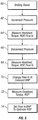
- a flow chart of the foregoing procedure includes the following.
- drilling operations are underway and the wellbore is being drilled ahead.
- the DAPC system ( FIG. 1 ) may be operated to cause the pressure in the annulus (115 in FIG. 1 ) to increase by a selected amount.
- the flow in is compared to the flow out. If the flow out is substantially the same as the flow out, the DAPC system is operated so that the annulus pressure is again increased. The foregoing is repeated, until at 46 there is indication that the flow out is less than the flow in.
- the annulus pressure proximate the bottom of the wellbore at that time will be used to establish, also at 46, a safe maximum fluid pressure at the bottom of the wellbore ("bottom hole pressure" or "BHP").
- the DAPC system may be operated to reduce the pressure in selected decrements.
- measurements of flow in and flow out are compared.
- the DAPC system can be operated to decrement the BHP further. The foregoing continues, until at 50 the flow out appears to exceed the flow in.
- the BHP determined at that time may be used to establish a safe lower pressure limit.
- FIG. 3 includes curves pore pressure and fracture pressure curves, 10 and 11, respectively which are substantially the same as those described above with reference to FIG. 2 . Pressure limits shown by curves 11 and 13 are also substantially the same as in FIG. 2 . Maximum and minimum pressures that can be safely sustained in the wellbore, at curves 14, and 15, will be further explained below. In the present example, optimum values for certain drilling operating parameters (defined above) may be determined during drilling. Referring to the flow chart in FIG. 5 , at 60, wellbore drilling operations are underway and drilling continues ahead. At 62, the DAPC system is operated to increment the pressure.
- drilling operating parameters such as the "hookload” (the amount of drill string weigh suspended by the drilling rig), the amount of torque applied to the drill string and the flow in rate are measured.
- a drilling response parameter such as the rate at which the wellbore is lengthened ("rate of penetration” or “ROP" can also be measured.
- the foregoing incrementing and measuring in some examples may be repeated until an indication of fracture pressure is obtained (as explained above with reference to FIGS. 2 and 4 ).
- the DAPC system may be operated to decrement the pressure.
- drilling operating parameters such as torque, hookload, flow in and response parameters such as ROP may be measured. Such decrementing and measuring in some may be repeated until an indication of pore pressure is obtained (as explained with reference to FIGS. 2 and 4 ).
- the flow in may be adjusted, e.g., by reducing the rate at which mud is pumped into the drill string.
- the flow in ordinarily should be maintained to at least an amount needed to lift the drill cuttings from the bottom of the wellbore (the "hole cleaning" lower limit).
- the DAPC system should be operated to maintain the BHP substantially constant while the flow rate is being adjusted.
- the hookload, torque and ROP may be measured. The foregoing may be repeated for a range of flow in rates.
- the foregoing measurements, made at selected values of BHP and flow in, may be analyzed to provide optimum values of certain drilling operating parameters such as the flow in and the BHP such that drilling response parameters, e.g., ROP are maximized.
- the foregoing analysis may also provide the minimum value of flow in (and consequent hydraulic horsepower delivered to the drill bit) that is consistent with safe drilling operations.
- the foregoing measurements i.e., incrementing and decrementing the BHP, if extended to the pressure limits as explained above, may enable determining the maximum and minimum mechanical pressure limits of the wellbore, e.g., along curves 14 and 15 in FIG. 5 .
- the various examples of the invention include adjusting the BHP and determining the response of the wellbore to such adjustment.
- "Response of the wellbore" or "wellbore response” is used as a general term to mean both formation pore pressure and fracture pressure determination and drilling response (e.g., changes in ROP with other drilling operating parameters maintained constant).
- Using methods according to the various aspects of the invention may provide better determination of wellbore casing depth and more efficient drilling.
Description
- The invention relates generally to the field of drilling wellbores through subsurface rock formations. More specifically, the invention relates to methods for determining and maintaining optimum wellbore fluid pressure during drilling and using wellbore fluid pressure response measurements to determine formation integrity and optimal drilling operating parameters.
- The exploration for and production of hydrocarbons from subsurface rock formations requires devices to reach and extract the hydrocarbons from the rock formations. Such devices are typically wellbores drilled from the Earth's surface to the hydrocarbon-bearing rock formations in the subsurface. The wellbores are drilled using a drilling rig. In its simplest form, a drilling rig is a device used to support a drill bit mounted on the end of a pipe known as a "drill string." A drill string is typically formed from lengths of drill pipe or similar tubular segments threadedly connected end to end. The drill string is longitudinally supported by the drilling rig structure at the surface, and may be rotated by devices associated with the drilling rig such as a top drive, or kelly/kelly busing assembly. A drilling fluid made up of a base fluid, typically water or oil, and various additives is pumped down a central opening in the drill string. The fluid exits the drill string through openings called "jets" in the body of the rotating drill bit. The drilling fluid then circulates back toward the surface in an annular space formed between the wellbore wall and the drill string, carrying the cuttings from the drill bit so as to clean the wellbore. The drilling fluid is also formulated such that the fluid pressure applied by the drilling fluid is typically greater than surrounding formation fluid pressure, thereby preventing formation fluids from entering the wellbore and collapse of the wellbore. However, such formulation also must provide that the hydrostatic pressure does not exceed the pressure at which the formations exposed by the wellbore will fail (fracture).
- It is known in the art that the actual pressure exerted by the drilling fluid ("hydrodynamic pressure") is related to its formulation as explained above, its other rheological properties, such as viscosity, and the rate at which the drilling fluid is moved through the drill string into the wellbore. It is also known in the art that by suitable control over the discharge of drilling fluid from the wellbore through the annular space, it is possible to exert pressure in the annular space between the drill string and the wellbore wall that exceeds the hydrostatic and hydrodynamic pressures by a selected amount. There have been developed a number of drilling systems called "dynamic annular pressure control" (DAPC) systems that perform the foregoing fluid discharge control. One such system is disclosed, for example, in
U.S. Patent No. 6,904,981 issued to van Riet and assigned to the assignee of the present invention. The DAPC system disclosed in the '981 patent includes a fluid backpressure system in which fluid discharge from the borehole is selectively controlled to maintain a selected pressure at the bottom of the borehole, and fluid is pumped down the drilling fluid return system to maintain annulus pressure during times when the mud pumps are turned off (and no mud is pumped through the drill string). A pressure monitoring system is further provided to monitor detected borehole pressures, model expected borehole pressures for further drilling and to control the fluid backpressure system.U.S. Patent No. 7,395,878 issued to Reitsma et al. and assigned to the assignee of the present invention describes a different form of DAPC system. - The formulation of the drilling fluid and when used, supplemental control over the fluid discharge such as by using a DAPC system, are intended to provide a selected fluid pressure in the wellbore during drilling. Such fluid pressure is, as explained above, selected so that fluid pressure from the pore spaces of certain subsurface formations does not enter the wellbore, so that the wellbore remains mechanically stable during continued drilling operations, and so that exposed rock formation are not hydraulically fractured during drilling operations. DAPC systems, in particular, provide increased ability to control the fluid pressure in the wellbore during drilling operations without the need to reformulate the drilling fluid extensively. As explained in the patents referenced above, using DAPC systems may also enable drilling wellbores through formations having fluid pressures and fracture pressures such that drilling using only formulated drilling fluid and uncontrolled fluid discharge from the wellbore is essentially impossible.
- Selection of the correct wellbore fluid pressure, even when using DAPC systems, however, requires at least prior estimation of the fluid pressure and the fracture pressures of the formations being drilling. Techniques known in the art for estimating such pressures include analysis of seismic surveys and gravity surveys. Other techniques may include refining estimates made from seismic and gravity surveys using actual drilling measurements and/or fluid pressure measurements from nearby wellbores. Irrespective of the techniques used to estimate formation fluid pressures and fracture pressures, the actual fluid pressures and fracture pressures encountered during drilling the wellbore may be different from those predicted or estimated. Inaccurate estimation of the fluid pressures and the fracture pressures may result in reduced drilling efficiency, increased risk of formation fracturing, increased risk of wellbore collapse, increased risk of drilling faults such as the pipe string becoming stuck in the wellbore, and increased risk of setting protective pipe or casing at incorrect depths with regard to the actual formation fluid pressures and fracture pressures.
US2003/0079912 , issued to Leuchtenberg, relates to the determination of pore and fracture pressures while drilling; said determination taking place by comparing the measured flow of drilling fluid out of a wellbore to a predicted flow of drilling fluid out of the wellbore calculated by a central acquisition and control device.US2003/0079912 ,WO 2007/005822 andWO 2008/106544 may be regarded as useful background for understanding the present disclosure. - There is a need for techniques to estimate the formation pore fluid pressures and formation fracture pressures while drilling, in order to better define formation integrity for correct casing depth selection and in order to better select drilling operating parameters for efficient drilling.
- It is an object of the present invention to provide a method for determining formation integrity during drilling of a wellbore. This object can be achieved by the features as defined by the
independent claim 1. Further enhancements are characterised by the dependent claims. A method for determining formation integrity during drilling of a wellbore according to one aspect of the invention includes determining an annulus fluid pressure in a wellbore during drilling thereof. The annulus pressure is adjusted by a predetermined amount. Flow rate of drilling fluid into the wellbore is compared to drilling fluid flow rate out of the wellbore. The adjusting and comparing is repeated. At least one of a formation pore pressure and a formation fracture pressure is determined when the compared flow rates differ by a selected amount. The method is characterized by the method being for determining formation integrity during active drilling of the wellbore while said wellbore is being drilled ahead. - Other aspects and advantages of the invention will be apparent from the following description of exemplary embodiments and the appended claims.
-
-
FIG. 1 shows an example of a wellbore drilling unit including a dynamic annular pressure control (DAPC) system. -
FIG. 2 shows an example of pore pressure and fracture pressure of subsurface rock formations, and bottom hole pressure limits established by an example method. -
FIG. 3 shows an example of pore pressure and fracture pressure of subsurface rock formations, and bottom hole pressure and mechanical limits established by an example method. -
FIG. 4 shows a flow chart of one example method. -
FIG. 5 shows a flow chart of another example method. - The method in general makes use of a dynamic annular pressure control (DAPC) system during drilling of a wellbore to adjust the fluid pressure in a wellbore annulus to selected values during drilling, and testing the response of the wellbore to such adjustment. Testing the wellbore response may include determining whether fluid is entering or being lost from the wellbore. Testing the wellbore response may also include determining response of a drilling system to the changed pressure, so as to select, for example, optimum fluid pressure and drilling fluid flow rate.
- An example of a drilling unit drilling a wellbore through subsurface rock formations, including a dynamic annular pressure control (DAPC) system is shown schematically in
FIG. 1 . Operation and details of the DAPC system may be substantially as described inU.S. Patent No. 7,395,878 issued to Reitsma et al. and assigned to the assignee of the present invention or may be as described inU.S. Patent No. 6,904,981 issued to van Riet and assigned to the assignee of the present invention. - The
drilling system 100 includes a hoisting device known as adrilling rig 102 that is used to support drilling operations through subsurface rock formations such as shown at 104. Many of the components used on thedrilling rig 102, such as a Kelly (or top drive), power tongs, slips, draw works and other equipment are not shown for clarity of the illustration. Awellbore 106 is shown being drilled through therock formations 104. Adrill string 112 is suspended from thedrilling rig 102 and extends into thewellbore 106, thereby forming an annular space (annulus) 115 between the wellbore wall and thedrill string 112, and/or between a casing 101 (when included in the wellbore) and thedrill string 112. One of the functions of thedrill string 112 is to convey a drilling fluid 150 (shown in a storage tank or pit 136), the use of which is for purposes as explained in the Background section herein, to the bottom of thewellbore 106 and into thewellbore annulus 115. - The
drill string 112 supports a bottom hole assembly ("BHA") 113 proximate the lower end thereof that includes adrill bit 120, and may include amud motor 118, asensor package 119, a check valve (not shown) to prevent backflow of drilling fluid from theannulus 115 into thedrill string 112. Thesensor package 119 may be, for example, a measurement while drilling and logging while drilling (MWD/LWD) sensor system. In particular theBHA 113 may include apressure transducer 116 to measure the pressure of the drilling fluid in theannulus 115 near the bottom of thewellbore 106. TheBHA 113 shown inFIG. 1 can also include atelemetry transmitter 122 that can be used to transmit pressure measurements made by thetransducer 116, MWD/LWD measurements as well as drilling information to be received at the surface. A data memory including a pressure data memory may be provided at a convenient place in theBHA 113 for temporary storage of measured pressure and other data (e.g., MWD/LWD data) before transmission of the data using thetelemetry transmitter 122. Thetelemetry transmitter 122 may be, for example, a controllable valve that modulates flow of the drilling fluid through thedrill string 112 to create pressure variations detectable at the surface. The pressure variations may be coded to represent signals from the MWD/LWD system and thepressure transducer 116. - The
drilling fluid 150 may be stored in areservoir 136, which is shown in the form of a mud tank or pit. Thereservoir 136 is in fluid communications with the intake of one or more mud pumps 138 that in operation pump thedrilling fluid 150 through aconduit 140. Anoptional flow meter 152 can be provided in series with one or more mud pumps 138, either upstream or downstream thereof. Theconduit 140 is connected to suitable pressure sealed swivels (not shown) coupled to the uppermost segment ("joint") of thedrill string 112. During operation, thedrilling fluid 150 is lifted from thereservoir 136 by thepumps 138, is pumped through thedrill string 112 and theBHA 113 and exits the through nozzles or courses (not shown) in thedrill bit 120, where it circulates the cuttings away from thebit 120 and returns them to the surface through theannulus 115. Thedrilling fluid 150 returns to the surface and goes through a drillingfluid discharge conduit 124 and optionally through various surge tanks and telemetry systems (not shown) to be returned, ultimately, to thereservoir 136. - A pressure isolating seal for the
annulus 115 is provided in the form of a rotating control head forming part of a blowout preventer ("BOP") 142. Thedrill string 112 passes through theBOP 142 and its associated rotating control head. When actuated, the rotating control head on theBOP 142 seals around thedrill string 112, isolating the fluid pressure therebelow, but still enables drill string rotation and longitudinal movement. Alternatively a rotating BOP (not shown) may be used for essentially the same purpose. The pressure isolating seal forms a part of a back pressure system used to maintain a selected fluid pressure in theannulus 115. - As the drilling fluid returns to the surface it goes through a side outlet below the pressure isolating seal (rotating control head) to a back pressure system configured to provide an adjustable back pressure on the drilling fluid in the
annulus 115. The back pressure system comprises a variable flow restrictive device, suitably in the form of a wearresistant choke 130. It will be appreciated that there exist chokes designed to operate in an environment where thedrilling fluid 150 contains substantial drill cuttings and other solids. Thechoke 130 is one such type and is further capable of operating at variable pressures, flowrates and through multiple duty cycles. - The
drilling fluid 150 exits thechoke 130 and flows through anoptional flow meter 126 to be directed through anoptional degasser 1 andsolids separation equipment 129. Thedegasser 1 andsolids separation equipment 129 are designed to remove excess gas and other contaminants, including drill cuttings, from thedrilling fluid 150. After passing through thesolids separation equipment 129, thedrilling fluid 150 is returned toreservoir 136. - The
flow meter 126 may be a mass-balance type or other high-resolution flow meter. Apressure sensor 147 can be optionally provided in the drillingfluid discharge conduit 124 upstream of the variable flow restrictive device (e.g., the choke 130). A flow meter, similar to flowmeter 126, may be placed upstream of the back pressure means 131 in addition to theback pressure sensor 147. Back pressure control means including apressure monitoring system 146 are provided for monitoring data relevant for the annulus pressure, and providing control signals to at least theback pressure system 131 and optionally also to the injection fluid injection system and/or to the primary pump. - In general terms, the required back pressure to obtain the desired annulus pressure proximate the bottom of the
wellbore 106 can be determined by obtaining at selected times information on the existing pressure of the drilling fluid in theannulus 115 in the vicinity of theBHA 113, referred to as the bottom hole pressure (BHP), comparing the information with a desired BHP and using the differential between these for determining a set-point back pressure. The set point back pressure is used for controlling the back pressure system in order to establish a back pressure close to the set-point back pressure. Information concerning the fluid pressure in theannulus 115 proximate theBHA 113 may be determined using an hydraulic model and measurements of drilling fluid pressure as it is pumped into the drill string and the rate at which the drilling fluid is pumped into the drill string (e.g., using a flow meter or a "stroke counter" typically provided with piston type mud pumps). The BHP information thus obtained may be periodically checked and/or calibrated using measurements made by thepressure transducer 116. - The injection fluid pressure in an
injection fluid supply 143 passage represents a relatively accurate indicator for the drilling fluid pressure in the drilling fluid gap at the depth where the injection fluid is injected into the drilling fluid gap. Therefore, a pressure signal generated by an injection fluid pressure sensor anywhere in the injection fluid supply passage, e.g., at 156, can be suitably used to provide an input signal for controlling the back pressure system, and for monitoring the drilling fluid pressure in thewellbore annulus 115. - The pressure signal can, if so desired, optionally be compensated for the density of the injection fluid column and/or for the dynamic pressure loss that may be generated in the injection fluid between the injection fluid pressure sensor in the injection fluid supply passage and where the injection into the drilling fluid return passage takes place, for instance, in order to obtain an exact value of the injection pressure in the drilling fluid return passage at the depth where the injection fluid is injected into the drilling fluid gap.
- The pressure of the injection fluid in the injection
fluid supply passage 141 is advantageously utilized for obtaining information relevant for determining the current bottom hole pressure. As long as the injection fluid is being injected into the drilling fluid return stream, the pressure of the injection fluid at the injection depth can be assumed to be equal to the drilling fluid pressure at theinjection point 144. Thus, the pressure as determined by the injectionfluid pressure sensor 156 can advantageously be used to generate a pressure signal for use as a feedback signal for controlling or regulating the back pressure system. - It should be noted that the change in hydrostatic contribution to the down hole pressure that would result from a possible variation in the injection fluid injection rate, is in close approximation compensated by the above described controlled readjusting of the back pressure means. Thus by controlling the back pressure means in accordance with the invention, the fluid pressure in the bore hole is almost independent of the rate of injection fluid injection.
- One possible way to use the pressure signal corresponding to the injection fluid pressure, is to control the back pressure system so as to maintain the injection fluid pressure on a certain suitable constant value throughout the drilling or completion operation. The accuracy is increased when the
injection point 144 is in close proximity to the bottom of the bore hole. - When the
injection point 144 is not so close to the bottom of thewellbore 106, the magnitude of the pressure differential over the part of the drilling fluid return passage stretching between theinjection point 144 and the bottom of thewellbore 106 is preferably to be established. For this, a hydraulic model can be utilized as will be described below. - In one example, the pressure difference of the drilling fluid in the drilling fluid return passage in a lower part of the
wellbore 106 extending between the injection fluid injection point and the bottom of the well bore, can be calculated using a hydraulic model taking into account inter alia the well geometry. Because the hydraulic model is generally only used for calculating the pressure differential over a relatively small section of thewellbore 106, the precision is expected to be much better than when the pressure differential over the entire wellbore length must be calculated. - In the present example, the
back pressure system 131 can be provided with aback pressure pump 128, in parallel fluid communication with thewellbore annulus 115 and thechoke 130, to pressurize the drilling fluid in the drillingfluid discharge conduit 124 upstream of the flowrestrictive device 130. The intake of theback pressure pump 128 is connected, viaconduit 119, to a drilling fluid supply which may be thereservoir 136. Astop valve 125 may be provided inconduit 119A/B to isolate the back pressure pump 128 from the drilling fluid supply Optionally, avalve 123 may be provided to selectively isolate the back pressure pump 128 from the drilling fluid discharge system. - The
back pressure pump 128 can be engaged to ensure that sufficient flow passes thechoke 130 to be able to maintain backpressure, even when there is insufficient flow coming from thewellbore annulus 115 to maintain pressure on thechoke 130. However, in some drilling operations it may often suffice to increase the weight of the fluid contained in theupper part 149 of the well bore annulus by reducing the injection fluid injection rate when the circulation rate ofdrilling fluid 150 via thedrill string 112 is reduced or interrupted. - The back pressure control system in the present example can generate the control signals for the back pressure system, suitably adjusting not only the
variable choke 130 but also theback pressure pump 128 and/orvalve 123. - In the present example, the
drilling fluid reservoir 136 comprises atrip tank 2 in addition to the mud tank or pit. A trip tank is normally used on a drilling rig to monitor drilling fluid gains and losses during movement of the drill string into and out of the wellbore 106 (known as "tripping operations"). It is noted that the trip tank may not be used extensively when drilling using a multiphase fluid system such as described hereinabove involving injection of a gas into the drilling fluid return stream, because thewellbore 106 may often remain alive or the drilling fluid level in the well drops when the injection gas pressure is bled off. However, in the present embodiment the functionality of the trip tank is maintained, for instance for occasions where a high-density drilling fluid is pumped down instead in high-pressure wells. - A valve manifold can be provided downstream of the
back pressure system 131 to enable selection of the reservoir to which drilling mud returning from thewellbore 106 is directed. In the present example, the valve manifold can include a twoway valve 5, allowing drilling fluid returning from the well or to be directed to themud pit 136 or thetrip tank 2. - The valve manifold may also include a two
way valve 125 provided for either feedingdrilling fluid 150 fromreservoir 136 viaconduit 119A or fromreservoir 2 viaconduit 119B to abackpressure pump 128 optionally provided in parallel fluid communication with the drillingfluid return passage 115 and thechoke 130. - In operation,
valve 125 would be operated to select eitherconduit 119A orconduit 119B, and thebackpressure pump 128 engaged to ensure sufficient flow passes the choke system to be able to maintain backpressure, even when there is no flow coming from theannulus 115. Unlike the drilling fluid passage inside the drill string, the injection fluid supply passage can preferably be dedicated to one task, which is supplying the injection fluid for injection into the drilling fluid gap. This way, its hydrostatic and hydrodynamic interaction with the injection fluid can be accurately determined and kept constant during an operation, so that the weight of the injection fluid and dynamic pressure loss in the supply passage can be accurately established. - The description of the drilling system above with reference to
FIG. 1 is to provide an example of drilling a wellbore using a DAPC system which can maintain a selected annulus fluid pressure near the bottom of thewellbore 106, i.e., the above- described BHP. Such system may include an hydraulics model that, as explained above, uses as input the rheological properties of thedrilling mud 150, the rate at which the mud flows into the wellbore, the wellbore and drill string configuration, pressure on the discharge conduit and if available, measurements of annulus fluid pressure (e.g., from transducer 116) proximate the bottom of the wellbore to supplement or refine calculations made by the hydraulics model. - The DAPC system may be operated in a specific manner to provide a measure of the formation integrity while drilling operations are underway, and may also be operated in a specific manner to provide indications of optimum values of drilling operating parameters. "Drilling operating parameters" as used herein is intended to mean parameters that are within the control of the operator of the drilling rig and may include, for example, the axial force applied to the drill bit 120 (by applying part of the axial loading of the
drill string 112 to the bit 120). Drilling operating parameters may also include an amount of torque applied to rotate thedrill string 112 at a selected speed. Drilling operating parameters may also include the rate at whichdrilling fluid 150 is moved into the drill string (measured, e.g., by monitoring the flow meter 152) and the selected BHP. - Referring now to
FIG. 2 , relationships between formation fluid pressure ("pore pressure") in the pore spaces of the rock formations (e.g., 104 inFIG. 1 ) and the fluid pressure ("fracture pressure") that if present in the wellbore can cause failure or fracturing of the formations will be explained to illustrate one example method of the invention. As explained above, the drilling fluid (150 inFIG. 1 ) is moved through the drill string (112 inFIG. 1 ) to circulate drill cuttings and to provide fluid pressure in the annulus (115 inFIG. 1 ). Fluid pressure in the annulus (115 inFIG. 1 ) is needed to prevent fluids in the pore spaces of certain permeable rock formations from entering the wellbore (106 inFIG. 1 ), and to prevent caving or collapse of the wellbore. Such function is performed by providing the drilling fluid with a selected density, and as is explained in the Reitsma et al. '878 patent, for example, by controlling the pressure in the drilling fluid discharge conduit (e.g., by using the backpressure system) through a combination of choke operation, fluid injection and backpressure application. Conversely, the fluid pressure in the wellbore annulus must not be permitted to exceed the fracture pressure, or the drilling fluid will be lost into the formations subject to fracturing as a result of exceeding the fracture pressure. - It is generally believed that formation fracture pressure of any particular formation in the subsurface is related to the weight of the rock formations above the particular formation in the subsurface (called "overburden"), and to the fluid pressure in the pore spaces of the formation ("pore pressure").
Curve 12 inFIG. 2 shows the expected fracture pressure generally increases with respect to depth in the subsurface. The formation pore pressure is shown bycurve 10. Generally, the formation pressure increases with respect to depth, however it is known that certain formations may have lower pore pressures that overlying formations. Such situation is reflected bycurve 10 beginning at a depth of about 3017 meters (9,900 feet). The pressure relationships shown inFIG. 2 are common, for example, in subsurface rock formations in the United States Gulf of Mexico where formations having pore pressures above the hydrostatic gradient of brine (called "overpressured" formations) are underlain by formations having pore pressures successively closer to the hydrostatic gradient of brine. The situation shown inFIG. 2 is known as a "pore pressure reversal." What is apparent inFIG. 2 is that the fracture pressure no longer increases linearly with respect to depth. If the BHP (resulting from drilling fluid density and backpressure) is maintained in expectation of higher fracture pressure than is actually present, the formations may fracture. It will be appreciated that the curves shown inFIG. 2 are scaled in units of pressure. The curves shown inFIG. 2 are also known in the art to be scaled in terms of pressure gradient. Pressure gradient is typically expressed in units of equivalent drilling fluid density ("mud weight"); such units known in the art of hydrocarbon wellbore drilling include pounds weight per gallon volume of drilling fluid (ppg), and include drilling fluid density in kg/m3 in the International System or SI unit. - The curves in the graph of
FIG. 2 may be estimated before commencement of drilling the wellbore. Such estimation may be made, for example, by analysis of gravity and seismic surveys to estimate the weight of the rock formations with respect to depth, and velocity analysis of seismic surveys to estimate the fluid pressure. Such techniques are well known in the art. Other information that may be available, such as formation fluid pressure tests and drilling records from nearby wellbores, may be used to refine the estimates made from gravity and seismic surveying. The invention is intended to refine further the estimates of the fracture pressure and pore pressure while drilling operations are underway. - For example, an important element of wellbore construction in situations such as the one shown in
FIG. 2 is placement of a pipe or casing (e.g., 101 inFIG. 1 ) to the correct depth to protect formations subject to fracturing, and as much as possible, to hydraulically isolate formations having lower fluid pressures therein to avoid the drill string becoming stuck in the wellbore by the action of differential pressure. The correct casing depth is related to the pore pressure of the exposed formations and the fracture pressure of the exposed formations, among other factors. - In an example method according to the invention, the DAPC system, e.g., as explained above with reference to
FIG. 1 , is operated during drilling to increase the bottom hole pressure above the selected set point. Increasing bottom hole pressure may be performed, for example, by any combination of increasing the pumping rate of the mud pump (138 inFIG. 1 ), increasing the rate of fluid injection from the injection pump (143 inFIG. 1 ), reducing the orifice of the choke (130 inFIG. 1 ) and operating the back pressure pump (128 inFIG. 1 ). The DAPC system may be operated to increase the pressure in selected increments, e.g., 690 kPa (100 pounds per square inch (psi)) or other selected increment. As the bottom hole pressure is successively increased, a measurement of drilling fluid volume or mass flow into the wellbore ("flow in"), e.g., using the flow meter (152 inFIG. 1 ), or using the "stroke counter" where the mud pumps (138 inFIG. 1 ) are reciprocating piston pumps, is compared with a measurement of the drilling fluid volume or mass flow out ("flow out") of the wellbore, e.g., using theflow meter 126. An indication that less drilling fluid is leaving the wellbore than is being pumped into the wellbore by a selected threshold amount or more may be inferred to be an indication that the bottom hole pressure is at or near the fracture pressure. Such indication may be used to establish a safe upper limit for bottom hole pressure, e.g., alongcurve 13 inFIG. 2 . - The DAPC system may also be operated to selectively reduce the bottom hole pressure. Such reduction may also be made in selected decrements, for example, 690 kPa (100 psi). Measurements of flow out and flow in are made and compared for each decrement. Measurements of flow out that exceed measurements of flow in above a selected threshold amount or more may indicate fluid entry into the wellbore as a result of insufficient bottom hole pressure. Such determinations may be used to establish a safe lower bottom hole pressure limit, e.g., along
curve 11 inFIG. 2 . - The foregoing procedures may be performed during active drilling of the wellbore (i.e., as the wellbore is lengthened by the action of the drill bit). As will be appreciated by those skilled in the art, as drilling continues, a depth may be approached at which the lowest safe pressure may approach or exceed the highest safe pressure. At such depth it is typically necessary to set a pipe or casing in the wellbore to protect the exposed subsurface rock formations so that drilling can continue safely. By making maximum and minimum safe pressure determinations during drilling of the wellbore as contrasted with relying on pre-drill estimates, it is expected that a maximum possible casing depth may be reached. By determining a maximum possible casing depth using the foregoing technique, it may be possible to avoid two occurrences that have a negative impact on the wellbore. First, setting casing too shallow may be avoided. Setting casing too shallow can have the effect of leaving formations exposed below the depth of the casing that cannot be drilled safely because of formation conditions such as the above described pore pressure reversal, or large increases in pore pressure gradient. In such circumstances it may be necessary to set additional casings coaxially within the existing casing. Such additional coaxial casings can substantially reduce the possible diameter of the wellbore and the ultimate productive capacity of the wellbore. The other occurrence that may be avoided is loss of the wellbore by reason of underground blowout or fracture failure of the formations being drilled. The above described method can assist the wellbore operator in minimizing the possibility of the foregoing two occurrences by determining a best possible casing depth.
- Referring to
FIG. 4 , a flow chart of the foregoing procedure includes the following. At 40, drilling operations are underway and the wellbore is being drilled ahead. At 42, the DAPC system (FIG. 1 ) may be operated to cause the pressure in the annulus (115 inFIG. 1 ) to increase by a selected amount. At 44, the flow in is compared to the flow out. If the flow out is substantially the same as the flow out, the DAPC system is operated so that the annulus pressure is again increased. The foregoing is repeated, until at 46 there is indication that the flow out is less than the flow in. The annulus pressure proximate the bottom of the wellbore at that time will be used to establish, also at 46, a safe maximum fluid pressure at the bottom of the wellbore ("bottom hole pressure" or "BHP"). - Conversely, and at 48 in
FIG. 4 , the DAPC system may be operated to reduce the pressure in selected decrements. At 50, measurements of flow in and flow out are compared. Also at 50, if the flow in and flow out are substantially the same, the DAPC system can be operated to decrement the BHP further. The foregoing continues, until at 50 the flow out appears to exceed the flow in. At 52, in such case, the BHP determined at that time may be used to establish a safe lower pressure limit. -
FIG. 3 includes curves pore pressure and fracture pressure curves, 10 and 11, respectively which are substantially the same as those described above with reference toFIG. 2 . Pressure limits shown bycurves FIG. 2 . Maximum and minimum pressures that can be safely sustained in the wellbore, atcurves FIG. 5 , at 60, wellbore drilling operations are underway and drilling continues ahead. At 62, the DAPC system is operated to increment the pressure. At 64, certain drilling operating parameters, such as the "hookload" (the amount of drill string weigh suspended by the drilling rig), the amount of torque applied to the drill string and the flow in rate are measured. A drilling response parameter, such as the rate at which the wellbore is lengthened ("rate of penetration" or "ROP") can also be measured. The foregoing incrementing and measuring in some examples may be repeated until an indication of fracture pressure is obtained (as explained above with reference toFIGS. 2 and4 ). At 66, the DAPC system may be operated to decrement the pressure. At 68, drilling operating parameters such as torque, hookload, flow in and response parameters such as ROP may be measured. Such decrementing and measuring in some may be repeated until an indication of pore pressure is obtained (as explained with reference toFIGS. 2 and4 ). - At 70, the flow in may be adjusted, e.g., by reducing the rate at which mud is pumped into the drill string. Those skilled in the art will appreciate that the flow in ordinarily should be maintained to at least an amount needed to lift the drill cuttings from the bottom of the wellbore (the "hole cleaning" lower limit). The DAPC system should be operated to maintain the BHP substantially constant while the flow rate is being adjusted. At 72, the hookload, torque and ROP may be measured. The foregoing may be repeated for a range of flow in rates.
- The foregoing measurements, made at selected values of BHP and flow in, may be analyzed to provide optimum values of certain drilling operating parameters such as the flow in and the BHP such that drilling response parameters, e.g., ROP are maximized. The foregoing analysis may also provide the minimum value of flow in (and consequent hydraulic horsepower delivered to the drill bit) that is consistent with safe drilling operations. The foregoing measurements, i.e., incrementing and decrementing the BHP, if extended to the pressure limits as explained above, may enable determining the maximum and minimum mechanical pressure limits of the wellbore, e.g., along curves 14 and 15 in
FIG. 5 . In the most general sense, the various examples of the invention include adjusting the BHP and determining the response of the wellbore to such adjustment. "Response of the wellbore" or "wellbore response" is used as a general term to mean both formation pore pressure and fracture pressure determination and drilling response (e.g., changes in ROP with other drilling operating parameters maintained constant). - Using methods according to the various aspects of the invention may provide better determination of wellbore casing depth and more efficient drilling.
- While the invention has been described with respect to a limited number of embodiments, those skilled in the art, having benefit of this disclosure, will appreciate that other embodiments can be devised which do not depart from the scope of the invention as disclosed herein. Accordingly, the scope of the invention should be limited only by the attached claims.
Claims (4)
- A method for determining formation integrity during drilling of a wellbore (106), comprising:determining an annulus fluid pressure in a wellbore (106) during drilling thereof; andadjusting the annulus pressure by a predetermined amount;comparing flow rate of drilling fluid (150) into the wellbore (106) to drilling fluid flow rate out of the wellbore (106);repeating the adjusting and comparing; anddetermining at least one of a formation pore pressure and a formation fracture pressure from the annulus pressure when the compared flow rates differ by a selected amount;the method being for determining formation integrity during active drilling of the wellbore (106), while said wellbore is being drilled ahead.
- The method of claim 1 wherein the adjusting comprises incrementing the annulus pressure, and the formation fracture pressure is determined when flow rate into the wellbore (106) exceeds flow rate out of the wellbore (106).
- The method of claim 1 wherein the adjusting comprises decrementing the annulus pressure and the formation pore pressure is determined when flow rate out of the wellbore (106) exceeds flow rate into the wellbore (106).
- The method of claim 1 further comprising using the determined fracture pressure or pore pressure to estimate a wellbore depth at which a casing (101) is to be set.
Applications Claiming Priority (2)
| Application Number | Priority Date | Filing Date | Title |
|---|---|---|---|
| US12/326,925 US7984770B2 (en) | 2008-12-03 | 2008-12-03 | Method for determining formation integrity and optimum drilling parameters during drilling |
| PCT/US2009/066422 WO2010065646A2 (en) | 2008-12-03 | 2009-12-02 | Method for determining formation integrity and optimum drilling parameters during drilling |
Publications (3)
| Publication Number | Publication Date |
|---|---|
| EP2368009A2 EP2368009A2 (en) | 2011-09-28 |
| EP2368009A4 EP2368009A4 (en) | 2013-05-22 |
| EP2368009B1 true EP2368009B1 (en) | 2019-11-20 |
Family
ID=42221778
Family Applications (1)
| Application Number | Title | Priority Date | Filing Date |
|---|---|---|---|
| EP09831057.6A Not-in-force EP2368009B1 (en) | 2008-12-03 | 2009-12-02 | Method for determining formation integrity and optimum drilling parameters during drilling |
Country Status (11)
| Country | Link |
|---|---|
| US (1) | US7984770B2 (en) |
| EP (1) | EP2368009B1 (en) |
| CN (1) | CN102272410B (en) |
| BR (1) | BRPI0922775B1 (en) |
| CL (1) | CL2011001337A1 (en) |
| EA (1) | EA023468B1 (en) |
| EG (1) | EG26416A (en) |
| MX (1) | MX2011005780A (en) |
| MY (1) | MY154155A (en) |
| PE (1) | PE20120369A1 (en) |
| WO (1) | WO2010065646A2 (en) |
Families Citing this family (25)
| Publication number | Priority date | Publication date | Assignee | Title |
|---|---|---|---|---|
| US8490719B2 (en) * | 2006-10-23 | 2013-07-23 | M-I L.L.C. | Method and apparatus for controlling bottom hole pressure in a subterranean formation during rig pump operation |
| US9435162B2 (en) | 2006-10-23 | 2016-09-06 | M-I L.L.C. | Method and apparatus for controlling bottom hole pressure in a subterranean formation during rig pump operation |
| CA2840725C (en) | 2006-11-07 | 2015-12-29 | Charles R. Orbell | Method of pressure testing a riser string |
| US8281875B2 (en) | 2008-12-19 | 2012-10-09 | Halliburton Energy Services, Inc. | Pressure and flow control in drilling operations |
| US9567843B2 (en) | 2009-07-30 | 2017-02-14 | Halliburton Energy Services, Inc. | Well drilling methods with event detection |
| EP2483513B1 (en) | 2010-02-25 | 2015-08-12 | Halliburton Energy Services, Inc. | Pressure control device with remote orientation relative to a rig |
| AU2011222568B2 (en) * | 2010-03-05 | 2014-01-09 | Safekick Americas Llc | System and method for safe well control operations |
| US8820405B2 (en) | 2010-04-27 | 2014-09-02 | Halliburton Energy Services, Inc. | Segregating flowable materials in a well |
| US8201628B2 (en) | 2010-04-27 | 2012-06-19 | Halliburton Energy Services, Inc. | Wellbore pressure control with segregated fluid columns |
| US8684109B2 (en) | 2010-11-16 | 2014-04-01 | Managed Pressure Operations Pte Ltd | Drilling method for drilling a subterranean borehole |
| US9574432B2 (en) | 2010-12-13 | 2017-02-21 | Schlumberger Technology Corporation | Optimized drilling |
| MY168333A (en) | 2011-04-08 | 2018-10-30 | Halliburton Energy Services Inc | Automatic standpipe pressure control in drilling |
| US9080407B2 (en) | 2011-05-09 | 2015-07-14 | Halliburton Energy Services, Inc. | Pressure and flow control in drilling operations |
| BR112014004638A2 (en) | 2011-09-08 | 2017-03-14 | Halliburton Energy Services Inc | method for maintaining a desired temperature at a location in a well, and, well system |
| US9033048B2 (en) * | 2011-12-28 | 2015-05-19 | Hydril Usa Manufacturing Llc | Apparatuses and methods for determining wellbore influx condition using qualitative indications |
| MX353838B (en) * | 2012-02-24 | 2018-01-31 | Halliburton Energy Services Inc | Well drilling systems and methods with pump drawing fluid from annulus. |
| US9823373B2 (en) | 2012-11-08 | 2017-11-21 | Halliburton Energy Services, Inc. | Acoustic telemetry with distributed acoustic sensing system |
| US11802480B2 (en) * | 2014-04-15 | 2023-10-31 | Halliburton Energy Services, Inc. | Determination of downhole conditions using circulated non-formation gasses |
| CN104500054B (en) * | 2014-12-15 | 2017-07-07 | 中国石油天然气集团公司 | The determination method and device of formation pore pressure |
| WO2016099483A1 (en) * | 2014-12-17 | 2016-06-23 | National Oilwell Dht L.P. | Method of pressure testing a wellbore |
| US11377917B2 (en) | 2016-12-22 | 2022-07-05 | Schlumberger Technology Corporation | Staged annular restriction for managed pressure drilling |
| US11746276B2 (en) | 2018-10-11 | 2023-09-05 | Saudi Arabian Oil Company | Conditioning drilling fluid |
| CN111852441B (en) * | 2019-04-29 | 2023-08-22 | 中国石油天然气股份有限公司 | Oil well collapse judging method and equipment |
| GB2582841B (en) * | 2019-08-19 | 2021-09-08 | Clear Solutions Holdings Ltd | Automated fluid system |
| US11028648B1 (en) * | 2020-11-05 | 2021-06-08 | Quaise, Inc. | Basement rock hybrid drilling |
Citations (2)
| Publication number | Priority date | Publication date | Assignee | Title |
|---|---|---|---|---|
| US20030079912A1 (en) * | 2000-12-18 | 2003-05-01 | Impact Engineering Solutions Limited | Drilling system and method |
| WO2008106544A2 (en) * | 2007-02-27 | 2008-09-04 | Precision Energy Services, Inc. | System and method for reservoir characterization using underbalanced drilling data |
Family Cites Families (6)
| Publication number | Priority date | Publication date | Assignee | Title |
|---|---|---|---|---|
| US7185719B2 (en) | 2002-02-20 | 2007-03-06 | Shell Oil Company | Dynamic annular pressure control apparatus and method |
| US6926081B2 (en) * | 2002-02-25 | 2005-08-09 | Halliburton Energy Services, Inc. | Methods of discovering and correcting subterranean formation integrity problems during drilling |
| JP3859543B2 (en) | 2002-05-22 | 2006-12-20 | レーザーフロントテクノロジーズ株式会社 | Laser processing equipment |
| WO2007005822A2 (en) * | 2005-07-01 | 2007-01-11 | Board Of Regents, The University Of Texas System | System, program products, and methods for controlling drilling fluid parameters |
| MY144145A (en) * | 2006-01-05 | 2011-08-15 | At Balance Americas Llc | Method for determining formation fluid entry into or drilling fluid loss from a borehole using a dynamic annular pressure control system |
| US20070227774A1 (en) | 2006-03-28 | 2007-10-04 | Reitsma Donald G | Method for Controlling Fluid Pressure in a Borehole Using a Dynamic Annular Pressure Control System |
-
2008
- 2008-12-03 US US12/326,925 patent/US7984770B2/en not_active Expired - Fee Related
-
2009
- 2009-12-02 BR BRPI0922775A patent/BRPI0922775B1/en not_active IP Right Cessation
- 2009-12-02 PE PE2011001153A patent/PE20120369A1/en active IP Right Grant
- 2009-12-02 MX MX2011005780A patent/MX2011005780A/en active IP Right Grant
- 2009-12-02 CN CN200980154288.5A patent/CN102272410B/en not_active Expired - Fee Related
- 2009-12-02 MY MYPI2011002504A patent/MY154155A/en unknown
- 2009-12-02 EA EA201170748A patent/EA023468B1/en not_active IP Right Cessation
- 2009-12-02 WO PCT/US2009/066422 patent/WO2010065646A2/en active Application Filing
- 2009-12-02 EP EP09831057.6A patent/EP2368009B1/en not_active Not-in-force
-
2011
- 2011-06-02 EG EG2011060905A patent/EG26416A/en active
- 2011-06-03 CL CL2011001337A patent/CL2011001337A1/en unknown
Patent Citations (2)
| Publication number | Priority date | Publication date | Assignee | Title |
|---|---|---|---|---|
| US20030079912A1 (en) * | 2000-12-18 | 2003-05-01 | Impact Engineering Solutions Limited | Drilling system and method |
| WO2008106544A2 (en) * | 2007-02-27 | 2008-09-04 | Precision Energy Services, Inc. | System and method for reservoir characterization using underbalanced drilling data |
Also Published As
| Publication number | Publication date |
|---|---|
| CN102272410B (en) | 2014-06-18 |
| US7984770B2 (en) | 2011-07-26 |
| EP2368009A4 (en) | 2013-05-22 |
| MX2011005780A (en) | 2011-09-06 |
| BRPI0922775A2 (en) | 2016-09-06 |
| BRPI0922775B1 (en) | 2019-09-03 |
| CN102272410A (en) | 2011-12-07 |
| EA023468B1 (en) | 2016-06-30 |
| WO2010065646A2 (en) | 2010-06-10 |
| EP2368009A2 (en) | 2011-09-28 |
| WO2010065646A3 (en) | 2010-07-29 |
| EA201170748A1 (en) | 2011-12-30 |
| EG26416A (en) | 2013-10-22 |
| PE20120369A1 (en) | 2012-05-13 |
| MY154155A (en) | 2015-05-15 |
| CL2011001337A1 (en) | 2011-09-02 |
| US20100133007A1 (en) | 2010-06-03 |
Similar Documents
| Publication | Publication Date | Title |
|---|---|---|
| EP2368009B1 (en) | Method for determining formation integrity and optimum drilling parameters during drilling | |
| US9328574B2 (en) | Method for characterizing subsurface formations using fluid pressure response during drilling operations | |
| US8567525B2 (en) | Method for determining fluid control events in a borehole using a dynamic annular pressure control system | |
| US6814142B2 (en) | Well control using pressure while drilling measurements | |
| EP1488073B2 (en) | Dynamic annular pressure control apparatus and method | |
| US7350597B2 (en) | Drilling system and method | |
| US7562723B2 (en) | Method for determining formation fluid entry into or drilling fluid loss from a borehole using a dynamic annular pressure control system | |
| US20120227961A1 (en) | Method for automatic pressure control during drilling including correction for drill string movement | |
| US20070227774A1 (en) | Method for Controlling Fluid Pressure in a Borehole Using a Dynamic Annular Pressure Control System | |
| US11199061B2 (en) | Closed hole circulation drilling with continuous downhole monitoring | |
| RU2748179C2 (en) | Applying pressure signal to determine annular space volume |
Legal Events
| Date | Code | Title | Description |
|---|---|---|---|
| PUAI | Public reference made under article 153(3) epc to a published international application that has entered the european phase |
Free format text: ORIGINAL CODE: 0009012 |
|
| 17P | Request for examination filed |
Effective date: 20110622 |
|
| AK | Designated contracting states |
Kind code of ref document: A2 Designated state(s): AT BE BG CH CY CZ DE DK EE ES FI FR GB GR HR HU IE IS IT LI LT LU LV MC MK MT NL NO PL PT RO SE SI SK SM TR |
|
| DAX | Request for extension of the european patent (deleted) | ||
| RIC1 | Information provided on ipc code assigned before grant |
Ipc: E21B 21/08 20060101AFI20130411BHEP Ipc: E21B 49/00 20060101ALI20130411BHEP Ipc: E21B 44/00 20060101ALI20130411BHEP |
|
| A4 | Supplementary search report drawn up and despatched |
Effective date: 20130418 |
|
| STAA | Information on the status of an ep patent application or granted ep patent |
Free format text: STATUS: EXAMINATION IS IN PROGRESS |
|
| 17Q | First examination report despatched |
Effective date: 20170221 |
|
| GRAP | Despatch of communication of intention to grant a patent |
Free format text: ORIGINAL CODE: EPIDOSNIGR1 |
|
| STAA | Information on the status of an ep patent application or granted ep patent |
Free format text: STATUS: GRANT OF PATENT IS INTENDED |
|
| INTG | Intention to grant announced |
Effective date: 20190619 |
|
| GRAS | Grant fee paid |
Free format text: ORIGINAL CODE: EPIDOSNIGR3 |
|
| GRAA | (expected) grant |
Free format text: ORIGINAL CODE: 0009210 |
|
| STAA | Information on the status of an ep patent application or granted ep patent |
Free format text: STATUS: THE PATENT HAS BEEN GRANTED |
|
| AK | Designated contracting states |
Kind code of ref document: B1 Designated state(s): AT BE BG CH CY CZ DE DK EE ES FI FR GB GR HR HU IE IS IT LI LT LU LV MC MK MT NL NO PL PT RO SE SI SK SM TR |
|
| RAP1 | Party data changed (applicant data changed or rights of an application transferred) |
Owner name: SCHLUMBERGER HOLDINGS LIMITED |
|
| REG | Reference to a national code |
Ref country code: GB Ref legal event code: FG4D |
|
| REG | Reference to a national code |
Ref country code: CH Ref legal event code: EP |
|
| REG | Reference to a national code |
Ref country code: DE Ref legal event code: R096 Ref document number: 602009060510 Country of ref document: DE |
|
| REG | Reference to a national code |
Ref country code: IE Ref legal event code: FG4D |
|
| REG | Reference to a national code |
Ref country code: AT Ref legal event code: REF Ref document number: 1204400 Country of ref document: AT Kind code of ref document: T Effective date: 20191215 |
|
| REG | Reference to a national code |
Ref country code: NL Ref legal event code: MP Effective date: 20191120 |
|
| REG | Reference to a national code |
Ref country code: NO Ref legal event code: T2 Effective date: 20191120 |
|
| REG | Reference to a national code |
Ref country code: LT Ref legal event code: MG4D |
|
| PG25 | Lapsed in a contracting state [announced via postgrant information from national office to epo] |
Ref country code: BG Free format text: LAPSE BECAUSE OF FAILURE TO SUBMIT A TRANSLATION OF THE DESCRIPTION OR TO PAY THE FEE WITHIN THE PRESCRIBED TIME-LIMIT Effective date: 20200220 Ref country code: FI Free format text: LAPSE BECAUSE OF FAILURE TO SUBMIT A TRANSLATION OF THE DESCRIPTION OR TO PAY THE FEE WITHIN THE PRESCRIBED TIME-LIMIT Effective date: 20191120 Ref country code: GR Free format text: LAPSE BECAUSE OF FAILURE TO SUBMIT A TRANSLATION OF THE DESCRIPTION OR TO PAY THE FEE WITHIN THE PRESCRIBED TIME-LIMIT Effective date: 20200221 Ref country code: LT Free format text: LAPSE BECAUSE OF FAILURE TO SUBMIT A TRANSLATION OF THE DESCRIPTION OR TO PAY THE FEE WITHIN THE PRESCRIBED TIME-LIMIT Effective date: 20191120 Ref country code: LV Free format text: LAPSE BECAUSE OF FAILURE TO SUBMIT A TRANSLATION OF THE DESCRIPTION OR TO PAY THE FEE WITHIN THE PRESCRIBED TIME-LIMIT Effective date: 20191120 Ref country code: SE Free format text: LAPSE BECAUSE OF FAILURE TO SUBMIT A TRANSLATION OF THE DESCRIPTION OR TO PAY THE FEE WITHIN THE PRESCRIBED TIME-LIMIT Effective date: 20191120 Ref country code: ES Free format text: LAPSE BECAUSE OF FAILURE TO SUBMIT A TRANSLATION OF THE DESCRIPTION OR TO PAY THE FEE WITHIN THE PRESCRIBED TIME-LIMIT Effective date: 20191120 Ref country code: NL Free format text: LAPSE BECAUSE OF FAILURE TO SUBMIT A TRANSLATION OF THE DESCRIPTION OR TO PAY THE FEE WITHIN THE PRESCRIBED TIME-LIMIT Effective date: 20191120 |
|
| PG25 | Lapsed in a contracting state [announced via postgrant information from national office to epo] |
Ref country code: HR Free format text: LAPSE BECAUSE OF FAILURE TO SUBMIT A TRANSLATION OF THE DESCRIPTION OR TO PAY THE FEE WITHIN THE PRESCRIBED TIME-LIMIT Effective date: 20191120 Ref country code: IS Free format text: LAPSE BECAUSE OF FAILURE TO SUBMIT A TRANSLATION OF THE DESCRIPTION OR TO PAY THE FEE WITHIN THE PRESCRIBED TIME-LIMIT Effective date: 20200320 |
|
| REG | Reference to a national code |
Ref country code: DE Ref legal event code: R119 Ref document number: 602009060510 Country of ref document: DE |
|
| PG25 | Lapsed in a contracting state [announced via postgrant information from national office to epo] |
Ref country code: PT Free format text: LAPSE BECAUSE OF FAILURE TO SUBMIT A TRANSLATION OF THE DESCRIPTION OR TO PAY THE FEE WITHIN THE PRESCRIBED TIME-LIMIT Effective date: 20200412 Ref country code: EE Free format text: LAPSE BECAUSE OF FAILURE TO SUBMIT A TRANSLATION OF THE DESCRIPTION OR TO PAY THE FEE WITHIN THE PRESCRIBED TIME-LIMIT Effective date: 20191120 Ref country code: DK Free format text: LAPSE BECAUSE OF FAILURE TO SUBMIT A TRANSLATION OF THE DESCRIPTION OR TO PAY THE FEE WITHIN THE PRESCRIBED TIME-LIMIT Effective date: 20191120 Ref country code: RO Free format text: LAPSE BECAUSE OF FAILURE TO SUBMIT A TRANSLATION OF THE DESCRIPTION OR TO PAY THE FEE WITHIN THE PRESCRIBED TIME-LIMIT Effective date: 20191120 Ref country code: CZ Free format text: LAPSE BECAUSE OF FAILURE TO SUBMIT A TRANSLATION OF THE DESCRIPTION OR TO PAY THE FEE WITHIN THE PRESCRIBED TIME-LIMIT Effective date: 20191120 |
|
| REG | Reference to a national code |
Ref country code: CH Ref legal event code: PL |
|
| REG | Reference to a national code |
Ref country code: AT Ref legal event code: MK05 Ref document number: 1204400 Country of ref document: AT Kind code of ref document: T Effective date: 20191120 |
|
| REG | Reference to a national code |
Ref country code: BE Ref legal event code: MM Effective date: 20191231 |
|
| PG25 | Lapsed in a contracting state [announced via postgrant information from national office to epo] |
Ref country code: MC Free format text: LAPSE BECAUSE OF FAILURE TO SUBMIT A TRANSLATION OF THE DESCRIPTION OR TO PAY THE FEE WITHIN THE PRESCRIBED TIME-LIMIT Effective date: 20191120 Ref country code: SM Free format text: LAPSE BECAUSE OF FAILURE TO SUBMIT A TRANSLATION OF THE DESCRIPTION OR TO PAY THE FEE WITHIN THE PRESCRIBED TIME-LIMIT Effective date: 20191120 Ref country code: SK Free format text: LAPSE BECAUSE OF FAILURE TO SUBMIT A TRANSLATION OF THE DESCRIPTION OR TO PAY THE FEE WITHIN THE PRESCRIBED TIME-LIMIT Effective date: 20191120 |
|
| PLBE | No opposition filed within time limit |
Free format text: ORIGINAL CODE: 0009261 |
|
| STAA | Information on the status of an ep patent application or granted ep patent |
Free format text: STATUS: NO OPPOSITION FILED WITHIN TIME LIMIT |
|
| 26N | No opposition filed |
Effective date: 20200821 |
|
| PG25 | Lapsed in a contracting state [announced via postgrant information from national office to epo] |
Ref country code: DE Free format text: LAPSE BECAUSE OF NON-PAYMENT OF DUE FEES Effective date: 20200701 Ref country code: IE Free format text: LAPSE BECAUSE OF NON-PAYMENT OF DUE FEES Effective date: 20191202 Ref country code: FR Free format text: LAPSE BECAUSE OF NON-PAYMENT OF DUE FEES Effective date: 20200120 Ref country code: LU Free format text: LAPSE BECAUSE OF NON-PAYMENT OF DUE FEES Effective date: 20191202 |
|
| PG25 | Lapsed in a contracting state [announced via postgrant information from national office to epo] |
Ref country code: LI Free format text: LAPSE BECAUSE OF NON-PAYMENT OF DUE FEES Effective date: 20191231 Ref country code: CH Free format text: LAPSE BECAUSE OF NON-PAYMENT OF DUE FEES Effective date: 20191231 Ref country code: PL Free format text: LAPSE BECAUSE OF FAILURE TO SUBMIT A TRANSLATION OF THE DESCRIPTION OR TO PAY THE FEE WITHIN THE PRESCRIBED TIME-LIMIT Effective date: 20191120 Ref country code: BE Free format text: LAPSE BECAUSE OF NON-PAYMENT OF DUE FEES Effective date: 20191231 Ref country code: AT Free format text: LAPSE BECAUSE OF FAILURE TO SUBMIT A TRANSLATION OF THE DESCRIPTION OR TO PAY THE FEE WITHIN THE PRESCRIBED TIME-LIMIT Effective date: 20191120 Ref country code: SI Free format text: LAPSE BECAUSE OF FAILURE TO SUBMIT A TRANSLATION OF THE DESCRIPTION OR TO PAY THE FEE WITHIN THE PRESCRIBED TIME-LIMIT Effective date: 20191120 |
|
| PG25 | Lapsed in a contracting state [announced via postgrant information from national office to epo] |
Ref country code: IT Free format text: LAPSE BECAUSE OF FAILURE TO SUBMIT A TRANSLATION OF THE DESCRIPTION OR TO PAY THE FEE WITHIN THE PRESCRIBED TIME-LIMIT Effective date: 20191120 |
|
| PG25 | Lapsed in a contracting state [announced via postgrant information from national office to epo] |
Ref country code: CY Free format text: LAPSE BECAUSE OF FAILURE TO SUBMIT A TRANSLATION OF THE DESCRIPTION OR TO PAY THE FEE WITHIN THE PRESCRIBED TIME-LIMIT Effective date: 20191120 |
|
| PG25 | Lapsed in a contracting state [announced via postgrant information from national office to epo] |
Ref country code: MT Free format text: LAPSE BECAUSE OF FAILURE TO SUBMIT A TRANSLATION OF THE DESCRIPTION OR TO PAY THE FEE WITHIN THE PRESCRIBED TIME-LIMIT Effective date: 20191120 Ref country code: HU Free format text: LAPSE BECAUSE OF FAILURE TO SUBMIT A TRANSLATION OF THE DESCRIPTION OR TO PAY THE FEE WITHIN THE PRESCRIBED TIME-LIMIT; INVALID AB INITIO Effective date: 20091202 |
|
| PGFP | Annual fee paid to national office [announced via postgrant information from national office to epo] |
Ref country code: NO Payment date: 20211209 Year of fee payment: 13 Ref country code: GB Payment date: 20211014 Year of fee payment: 13 |
|
| PG25 | Lapsed in a contracting state [announced via postgrant information from national office to epo] |
Ref country code: TR Free format text: LAPSE BECAUSE OF FAILURE TO SUBMIT A TRANSLATION OF THE DESCRIPTION OR TO PAY THE FEE WITHIN THE PRESCRIBED TIME-LIMIT Effective date: 20191120 |
|
| PG25 | Lapsed in a contracting state [announced via postgrant information from national office to epo] |
Ref country code: MK Free format text: LAPSE BECAUSE OF FAILURE TO SUBMIT A TRANSLATION OF THE DESCRIPTION OR TO PAY THE FEE WITHIN THE PRESCRIBED TIME-LIMIT Effective date: 20191120 |
|
| REG | Reference to a national code |
Ref country code: NO Ref legal event code: MMEP |
|
| GBPC | Gb: european patent ceased through non-payment of renewal fee |
Effective date: 20221202 |
|
| PG25 | Lapsed in a contracting state [announced via postgrant information from national office to epo] |
Ref country code: NO Free format text: LAPSE BECAUSE OF NON-PAYMENT OF DUE FEES Effective date: 20221231 Ref country code: GB Free format text: LAPSE BECAUSE OF NON-PAYMENT OF DUE FEES Effective date: 20221202 |
|
| P01 | Opt-out of the competence of the unified patent court (upc) registered |
Effective date: 20231208 |