EP2367136A1 - Tag communication apparatus, tag communication apparatus control method, and tag communication apparatus control program - Google Patents
Tag communication apparatus, tag communication apparatus control method, and tag communication apparatus control program Download PDFInfo
- Publication number
- EP2367136A1 EP2367136A1 EP11153764A EP11153764A EP2367136A1 EP 2367136 A1 EP2367136 A1 EP 2367136A1 EP 11153764 A EP11153764 A EP 11153764A EP 11153764 A EP11153764 A EP 11153764A EP 2367136 A1 EP2367136 A1 EP 2367136A1
- Authority
- EP
- European Patent Office
- Prior art keywords
- data
- unit
- rfid tag
- compressed
- tag
- Prior art date
- Legal status (The legal status is an assumption and is not a legal conclusion. Google has not performed a legal analysis and makes no representation as to the accuracy of the status listed.)
- Granted
Links
Images


Classifications
-
- G—PHYSICS
- G06—COMPUTING OR CALCULATING; COUNTING
- G06K—GRAPHICAL DATA READING; PRESENTATION OF DATA; RECORD CARRIERS; HANDLING RECORD CARRIERS
- G06K7/00—Methods or arrangements for sensing record carriers, e.g. for reading patterns
- G06K7/0008—General problems related to the reading of electronic memory record carriers, independent of its reading method, e.g. power transfer
-
- G—PHYSICS
- G06—COMPUTING OR CALCULATING; COUNTING
- G06K—GRAPHICAL DATA READING; PRESENTATION OF DATA; RECORD CARRIERS; HANDLING RECORD CARRIERS
- G06K7/00—Methods or arrangements for sensing record carriers, e.g. for reading patterns
- G06K7/10—Methods or arrangements for sensing record carriers, e.g. for reading patterns by electromagnetic radiation, e.g. optical sensing; by corpuscular radiation
- G06K7/10009—Methods or arrangements for sensing record carriers, e.g. for reading patterns by electromagnetic radiation, e.g. optical sensing; by corpuscular radiation sensing by radiation using wavelengths larger than 0.1 mm, e.g. radio-waves or microwaves
- G06K7/10366—Methods or arrangements for sensing record carriers, e.g. for reading patterns by electromagnetic radiation, e.g. optical sensing; by corpuscular radiation sensing by radiation using wavelengths larger than 0.1 mm, e.g. radio-waves or microwaves the interrogation device being adapted for miscellaneous applications
- G06K7/10475—Methods or arrangements for sensing record carriers, e.g. for reading patterns by electromagnetic radiation, e.g. optical sensing; by corpuscular radiation sensing by radiation using wavelengths larger than 0.1 mm, e.g. radio-waves or microwaves the interrogation device being adapted for miscellaneous applications arrangements to facilitate interaction with further interrogation devices, e.g. such that at least two interrogation devices may function and cooperate in a network of such devices
Definitions
- the present invention relates to a tag communication apparatus that conducts communication with an RFID tag through a radio wave, a tag communication apparatus control method, and a tag communication apparatus control program.
- RFID Radio Frequency Identification
- a tag communication apparatus that is of a reader/writer conducts wireless communication with an RFID tag (wireless tag).
- the RFID tag receives attention as replacement of a barcode particularly in the field of logistics, and the RFID tag is expected to become explosively widespread in the near future.
- a name, a manufacturing date, various pieces of information depending on the intended use of target goods, and pieces of personal information such as a name and a date of birth are stored in a storage space of the RFID tag.
- the information to be stored in the storage space of the RFID tag is expected to be increased, and a demand for increasing a storage capacity of the RFID tag arises.
- Japanese Unexamined Patent Publication No. 2007-213115 discloses a technique of storing first information and second information in the RFID tag. Contents of the second information are identical to those of the first information, and the second information is processed in a mode different from that of the first information (for example, compression).
- Japanese Unexamined Patent Publication No. 2009-15606 discloses a technique of improving security of information stored in the RFID tag.
- the RFID tag includes a unit that integrates the number of response times to a signal from the tag communication apparatus, the RFID tag does not send back a response when the number of response times reaches a predetermined number of times.
- the first information to be stored in the RFID tag and the second information in which contents are identical to those of the first information while the second information is processed in the mode different from that of the first information, are transmitted from the tag communication apparatus to the RFID tag. Therefore, even if the first information is compressed to form the second information, the time necessary for the communication is lengthened, and the shortening of the communication time is not achieved.
- the present invention has been devised to solve the problems described above, and an object thereof is to implement a tag communication apparatus that can shorten the time necessary for the communication with the RFID tag.
- a tag communication apparatus that conducts wireless communication with an RFID tag through a radio wave
- the tag communication apparatus includes: a data obtaining unit that obtains transmit data transmitted to the RFID tag: a data compression unit that compresses at least part of the transmit data obtained by the data obtaining unit and outputs compressed data; and a transmission unit that transmits the part of compressed data, which is compressed and output by the data compression unit, to the RFID tag.
- a method for controlling a tag communication apparatus that conducts wireless communication with an RFID tag through a radio wave, the method includes the steps of: obtaining transmit data transmitted to the RFID tag: compressing at least part of the transmit data obtained in the data obtaining step and outputting compressed data; and transmitting the part of compressed data, which is compressed and output in the data compression step, to the RFID tag.
- At least part of the transmit data obtained as the data transmitted to the RFID tag is compressed, and the compressed data that is of the data after the compression for the compressed part is transmitted to the RFID tag. Therefore, the amount of data to be transmitted can be reduced smaller than the data that is not compressed, the shortening of the communication time between the tag communication apparatus and the RFID tag can be achieved. A larger amount of information can be stored in the RFID tag by the same data amount.
- the tag communication apparatus in accordance with the aspect of the invention may further include a space information producing unit that produces space information in which a storage space in a storage unit of the RFID tag is correlated with stored information, wherein the data obtaining unit obtains the plurality of pieces of transmit data, the data compression unit compresses the plurality of pieces of transmit data obtained by the data obtaining unit and outputs a plurality of pieces of compressed data, the space information producing unit produces compressed data space information about that which compressed data in the plurality of pieces of compressed data is correlated with the space where the compressed data is stored in the storage unit of the RFID tag, and the transmission unit transmits the plurality of pieces of compressed data output from the data compression unit and the compressed data space information produced by the space information producing unit.
- a space information producing unit that produces space information in which a storage space in a storage unit of the RFID tag is correlated with stored information
- the obtained plural pieces of transmit data are compressed, and the compressed data space information about that which compressed data in the plural pieces of compressed data is correlated with the space where the compressed data is stored in the storage unit of the RFID tag is produced.
- the plural pieces of compressed data and the compressed data space information are transmitted to the RFID tag.
- the table in which the storage space and the stored information are correlated with each other does not exist, only one piece of data can be transmitted.
- the plural pieces of data can be transmitted to the RFID tag because the compressed data space information about that which compressed data is correlated with the space where the compressed data is stored in the storage unit of the RFID tag is transmitted.
- the tag communication apparatus in accordance with the aspect of the invention may further include: an empty space determining unit that determines whether an empty space where the compressed data can be stored exists in the storage unit of the RFID tag; and a space shortage information transmission unit that transmits space shortage information indicating no empty space to a source device of the transmit data obtained by the data obtaining unit when the empty space determining unit determines that the empty space does not exist.
- the source device can recognize that the empty space where the transmit data is stored does not exist in the RFID tag.
- the data compression unit may count the numbers of appearance times of bits of the data bit string in the transmit data, the data compression unit directly may output the transmit data when the number of appearance times of the bit having the shorter bit information transmission time is more than that of the bit having the longer bit information transmission time, and the data compression unit may produce and output converted data in which the bits of the data bit string in the transmit data are replaced with each other when the number of appearance times of the bit having the longer bit information transmission time is more than that of the bit having the shorter bit information transmission time.
- the transmission time of the whole transmit data can be shortened when the bits are replaced with each other in the case where the number of appearance times of the bit having the longer bit information transmission time is more than that of the bit having the shorter bit information transmission time. Therefore, the time necessary for the communication between the tag communication apparatus and the RFID tag, that is, the time necessary to transmit the data from the tag communication apparatus to the RFID tag and the time necessary to receive the data from the RFID tag to the tag communication apparatus can be shortened.
- the numbers of appearance times of the bits of the data bit string is counted, and the data is converted by the simple process of comparing the numbers of appearance times of the bits to perform the data conversion, so that a processing load can be reduced lighter than the conventional compression method.
- the tag communication apparatus in accordance with the aspect of the invention may further include: a compressed data obtaining unit that obtains from the RFID tag the compressed data transmitted from the transmission unit to the RFID tag; and a data decompression unit that decompresses the compressed data obtained by the compressed data obtaining unit.
- the tag communication apparatus in accordance with the aspect of the invention may further include: a compressed data obtaining unit that obtains the desired compressed data by using compressed data space information transmitted from the transmission unit to the RFID tag; and a data decompression unit that decompresses the compressed data obtained by the compressed data obtaining unit.
- the desired compressed data can be obtained and decompressed in the plural pieces of compressed data transmitted to the RFID tag. Therefore, contents of the desired compressed data can be recognized.
- the tag communication apparatus may be implemented by a computer. In such cases, the tag communication apparatus is implemented by operating the computer as each unit. Therefore, a control program of the tag communication apparatus in which the tag communication apparatus is implemented by the computer and a computer-readable recording medium in which the control program is recorded are also included in the invention.
- the tag communication apparatus of the invention includes: the data obtaining unit that obtains the transmit data transmitted to the RFID tag; the data compression unit that compresses at least part of the transmit data obtained by the data obtaining unit and outputs compressed data: and the transmission unit that transmits the part of compressed data, which is compressed and output by the data compression unit, to the RFID tag.
- the tag communication apparatus control method includes the steps of: obtaining the transmit data transmitted to the RFID tag; compressing at least part of the transmit data obtained in the data obtaining step and outputting compressed data; and transmitting the part of compressed data, which is compressed and output in the data compression step, to the RFID tag.
- the amount of data to be transmitted is reduced compared with the case where the data is not compressed, so that advantageously the time necessary for the communication between the tag communication apparatus and the RFID tag can be shortened. Additional, the larger amount of information can advantageously be stored in the RFID tag by the same data amount.
- An RFID reader/writer (tag communication apparatus) 1 conducts wireless communication with an RFID tag 3 to read and write data.
- the data is transmitted to the RFID tag 3 while compressed, whereby an information amount of the transmit data is reduced to achieve shortening of a transmission time.
- the compressed data is written in the RFID tag 3, it is necessary to perform decoding compatible with a compression format in order to read the data written in the RFID tag 3. Therefore, security of the data written in the RFID tag 3 is improved.
- Fig. 2A is a view illustrating a configuration of the RFID reader/writer 1 of the embodiment
- Fig. 2B is a view illustrating a configuration of a conventional RFID reader/writer.
- the RFID reader/writer 1 when the RFID reader/writer 1 receives the data to be written in the RFID tag 3 from a Personal Computer (PC) 2 that is of a high-order instrument, the RFID reader/writer 1 compresses the received data to convert the data into a format suitable to the transmission, and the RFID reader/writer 1 transmits the data to the RFID tag 3 through an antenna 130.
- PC Personal Computer
- an RFID reader/writer 100 directly converts data, which is received from the PC 2 and written in the RFID tag 3, into a format suitable to the transmission to transmit the data to the RFID tag 3 through the antenna 130.
- the data transmitted from the RFID reader/writer 1 to the RFID tag 3 is compressed, so that the amount of data to be transmitted can be reduced to shorten the transmission time.
- the RFID reader/writer 1 of the embodiment will be described with reference to Fig. 1 .
- the RFID reader/writer 1 includes a controller 10, a storage unit 11, a wireless processing unit (transmission unit) 12, an antenna unit 13, and an external I/F unit (data obtaining unit) 14.
- the controller 10 totally controls an operation of the RFID reader/writer 1.
- the controller 10 includes a PC-based computer.
- the operation of the RFID reader/writer 1 is controlled by causing the computer to execute a control program.
- the program recorded in a removable media such as a CD-ROM may be read in and executed by the computer, or the program installed in a hard disk may be read in and executed by the computer.
- the program is down-loaded through the external I/F unit 14 and installed in the hard disk, and the program may be read in and executed by the computer.
- the controller 10 also includes a tag controller (space information producing unit, empty space determining unit, space shortage information transmission unit) 21 and a data compression/decompression unit (data compression unit, data decompression unit, compressed data obtaining unit) 22.
- the tag controller 21 transmits a predetermined command to the RFID tag 3 through the wireless processing unit 12 and the antenna unit 13 and processes a command received from the RFID tag 3.
- the tag controller 21 makes a request for the RFID tag 3 to transmit file data.
- the tag controller 21 computes an address map from the file data to determine whether the data can be written in the RFID tag 3.
- the tag controller 21 produces file information (space information and compressed data space information) that is of data to be written in a file table area 505 with respect to the data to be written in the RFID tag 3, and the tag controller 21 transmits the file information to the RFID tag 3.
- the tag controller 21 transmits data (space shortage information) indicating that the RFID tag 3 has no space where the data is written to a high-order instrument (source device) of the RFID reader/writer 1 through the external I/F unit 14.
- the high-order instrument is a source of the data to be written in the RFID tag 3.
- the file data means data in which a storage space and stored information are correlated with each other in a memory 35 of the RFID tag 3.
- the RFID reader/writer 1 can write plural pieces of data in the RFID tag 3 by producing the file data.
- the data compression/decompression unit 22 compresses the data, which is obtained through the external I/F unit 14 and written in the RFID tag 3.
- the data compression/decompression unit 22 computes a data length of the compressed data that is of the data after the compression, and the data compression/decompression unit 22 transmits the compressed data and the data length of the data to the wireless processing unit 12. The detailed data compression is described later.
- the data compression/decompression unit 22 obtains the compressed data, transmitted from the RFID tag 3 through the antenna unit 13 and the wireless processing unit 12, and decompresses the compressed data.
- the data compression/decompression unit 22 computes a storage space for the desired compressed data from the file data, obtains the compressed data written in the storage space, and decompresses the compressed data.
- the storage unit 11 includes a nonvolatile storage device such as the hard disk. Examples of contents stored in the storage unit 11 include the control program, an OS (operating system) program, various programs and various pieces of data.
- OS operating system
- the wireless processing unit 12 converts the data, received from the controller 10, into a format suitable to wireless transmission to transmit the converted wireless signal to the outside through the antenna unit 13.
- the wireless processing unit 12 also converts the wireless signal, received from the outside through the antenna unit 16, into the original format to transmit the converted data to the controller 10.
- the wireless processing unit 12 includes an A/D (Analog-to-Digital) conversion circuit, a D/A (Digital-to-Analog) conversion circuit, a modulation/demodulation circuit, and an RF circuit.
- the antenna unit 13 transmits the wireless signal from the wireless processing unit 12 to the outside in the form of a radio wave, and the antenna unit 13 converts the radio wave received from the outside into the wireless signal to transmit the wireless signal to the wireless processing unit 12.
- the antenna unit 13 includes the antenna 130 and an oscillation circuit.
- the external I/F unit 14 conducts communication with the external device such as the PC.
- USB Universal Serial Bus
- IEEE1394 IEEE1394, and Ethernet (registered trademark) can be cited as an example of an interface standard of the external I/F unit 14.
- the usual RFID tag does not include a power supply such as a battery, but a circuit is operated by an electric power transmitted from the RFID reader/writer in the form of the radio wave, whereby the RFID tag conducts wireless communication with the RFID reader/writer.
- the RFID tag 3 includes an antenna unit 30 and a wireless communication IC 31.
- the antenna unit 30 receives the radio wave from the RFID reader/writer 1 as a power source used to operate the wireless communication IC 31.
- the antenna unit 30 converts the radio wave received from the RFID reader/writer 1 into the wireless signal to transmit the wireless signal to the wireless communication IC 31, and the antenna unit 30 converts the wireless signal from the wireless communication IC 31 into the radio wave to transmit the radio wave to the RFID reader/writer 1.
- the antenna unit 30 includes an antenna and an oscillation circuit.
- the wireless communication IC 31 Based on the signal received from the RFID reader/writer 1 through the antenna unit 30, the wireless communication IC 31 stores the data from the RFID reader/writer 1 or transmits the stored data to the RFID reader/writer 1 through the antenna unit 30. As illustrated in Fig. 5 , the wireless communication IC 31 includes a power supply unit 32, a wireless processing unit 33, a controller 34, and a memory 35.
- a rectifying circuit rectifies an inductive voltage, which is generated by the antenna unit 30 receiving the radio wave, a power supply circuit adjusts the generated voltage to a predetermined voltage, and then the voltage is supplied to each unit of the wireless communication IC 31.
- the power supply unit 32 includes a bridge diode and a voltage adjusting capacitor.
- the wireless processing unit 33 converts the wireless signal received from the outside through the antenna unit 30 into the original format to transmit the converted data to the controller 34, and the wireless processing unit 33 converts the data received from the controller 34 into the format suitable to the wireless transmission to transmit the converted wireless signal to the outside through the antenna unit 30.
- the wireless processing unit 33 includes an A/D (Analog-to-Digital) conversion circuit, a D/A (Digital-to-Analog) conversion circuit, a modulation/demodulation circuit, and an RF circuit.
- the controller 34 totally controls an operation of the wireless communication IC 31.
- the controller 34 includes a logic operation circuit and a register, and the controller 34 acts as a computer.
- the operation is controlled by causing the computer to execute a control program.
- the program installed in the memory 35 such as a ROM (Read Only Memory) may be read in and executed by the computer.
- the program is down-loaded from the RFID reader/writer 1 through the antenna unit 30 and the wireless processing unit 33 and installed in the memory 35, and the program may be read in and executed by the computer.
- the controller 34 Based on the data received from the RFID reader/writer 1 through the antenna unit 30 and the wireless processing unit 33. the controller 34 stores the data from the RFID reader/writer 1 in the memory 35, and reads the data stored in the memory 35 to transmit the data to the RFID reader/writer 1 through the wireless processing unit 33 and the antenna unit 30.
- the memory 35 includes a semiconductor memory such as the ROM, an SRAM (Static RAM), and an FeRAM (ferroelectric memory). Examples of contents stored in the memory 35 include the above described control program, various programs, and various pieces of data. Desirably a nonvolatile memory such as the ROM and a low-power-consumption memory such as the SRAM and the FeRAM are used, because the radio wave transmitted from the RFID reader/writer is used as the power source in the wireless communication IC 31.
- a semiconductor memory such as the ROM, an SRAM (Static RAM), and an FeRAM (ferroelectric memory). Examples of contents stored in the memory 35 include the above described control program, various programs, and various pieces of data.
- a nonvolatile memory such as the ROM and a low-power-consumption memory such as the SRAM and the FeRAM are used, because the radio wave transmitted from the RFID reader/writer is used as the power source in the wireless communication IC 31.
- Fig. 4 illustrates a structure of the memory 35 when one kind of the data is stored
- Fig. 5 illustrates a structure of the memory 35 when plural kinds of the pieces of data are stored.
- the memory 35 has a structure including a data length write area 401 in which a data length of the stored data is written and a compressed data write area 402 in which the compressed data is written. Because the data to be written is compressed, the data length of the data to be written becomes variable. Therefore, possibly the compressed data cannot be read unless the data length of the compressed data is written.
- the memory 35 has a structure including a file table area 505 in which a file name, a file size, and a file storage starting address of each of the pieces of data to be written are written and a compressed data write area 506 in which the compressed data is written. This is because, when the plural kinds of the pieces of data are stored, the data cannot be read unless information indicating where the data is written exists.
- Fig. 5 illustrates an example in which log data 501a of an inspection process 1, log data 502a of an inspection process 2, and log data 503a of an inspection process 3 are written in the RFID tag 3 as the plural kinds of the pieces of data.
- the pieces of data are stored in the RFID tag 3
- the pieces of data are compressed to produce pieces of file information indicating file names, file sizes, and file storage starting addresses of compressed data 501b of the inspection process 1, compressed data 502b of the inspection process 2, and compressed data 503b of the inspection process 3.
- the file storage starting address is used when the compressed data is written in the compressed data write area 506, Then the produced pieces of file information are written in the file table area 505 of the memory 35.
- the file name, file size, and file storage starting address, used in writing the compressed data in the compressed data write area 506, of the compressed data 501 b of the inspection process 1 are written in a data information storage area 511 of the inspection process 1 in the file table area 505.
- the file name, file size, and file storage starting address, used in writing the compressed data in the compressed data write area 506, of the compressed data 502b of the inspection process 2 are written in a data information storage area 512 of the inspection process 2 in the file table area 505.
- the file name, file size, and file storage starting address, used in writing the compressed data in the compressed data write area 506, of the compressed data 503b of the inspection process 3 are written in a data information storage area 513 of the inspection process 3 in the file table area 505.
- the compressed data 501 b of the inspection process 1, the compressed data 502b of the inspection process 2, and the compressed data 503b of the inspection process 3 are written in position, indicated by the file storage starting addresses thereof, in the compressed data write area 506.
- Fig. 6 illustrates a processing flow when the one kind of the data is written in the RFID tag 3
- Fig. 7 illustrates a processing flow when the plural kinds of the pieces of data are written in the RFID tag 3.
- the external I/F unit 14 of the RFID reader/writer 1 obtains the data to be written in the RFID tag 3 from the high-order instrument (data obtaining step in S601).
- the data compression/decompression unit 22 compresses the data obtained by the external I/F unit 14 (data compression step in S602).
- the data compression/decompression unit 22 computes the data length of the compressed data that is of the data after the compression (S603).
- the computed data length is transmitted to the RFID tag 3 through the wireless processing unit 12 and the antenna unit 13 (transmission step in S604).
- the RFID tag 3 writes the received data length in the memory 35 (S605).
- the RFID reader/writer 1 transmits the compressed data compressed by the data compression/decompression unit 22 to the RAID tag 3 (S606).
- the RFID tag 3 When receiving the compressed data, the RFID tag 3 writes the compressed data in the compressed data write area 402 of the memory 35 (S607). Therefore, the processing of writing the one kind of the data to be written in the RFID tag 3 is ended.
- the external I/F unit 14 of the RFID reader/writer 1 obtains the plural kinds of the pieces of data to be written in the RFID tag 3 (S701).
- the tag controller 21 makes a request for the RFID tag 3 to transmit the file table (S702).
- the RFID tag 3 transmits the file table to the RFID reader/writer 1 in response to the request (S703).
- the tag controller 21 computes the address map indicating the position where the data is written in the memory 35 (S705).
- the data compression/decompression unit 22 compresses the plural kinds of the pieces of data obtained by the external I/F unit 14 (S706), and the data compression/decompression unit 22 computes the data length of each of the pieces of data that are of the pieces of data after the compression (S707).
- the tag controller 21 determines whether the compressed data can be written in the memory 35 from the computed address map and data length (S708). When determining that the compressed data can be written in the memory 35 (YES in S708), the tag controller 21 produces the file information that is of the data written in the file table area 505 of the memory 35 (S710). The tag controller 21 transmits the produced file information to the RFID tag 3 (S711).
- the RFID tag 3 writes the received file information in file table area 505, of the memory 35 (S712).
- the RFID reader/writer 1 transmits the pieces of compressed data to the RFID tag 3 (S713).
- the RFID tag 3 writes the received pieces of compressed data to the compressed data write area 506 of the memory 35 (S714).
- the tag controller 21 transmits an address over error indicating that the compressed data cannot be written in the RFID tag 3 to the high-order instrument, which is of the source of the data to be written in the RFID tag 3, through the external I/F unit 14 (S709). Therefore, the processing of writing the plural kinds of the pieces of data to be written in the RFID tag 3 is ended.
- Fig. 8 is a view illustrating the case where the data is compressed in an LZH format
- Fig. 9 to Fig. 11 are views illustrating the case where the data is converted in a compression format (hereinafter referred to as a "0-1" inversion format) in which "0" and "1" are inverted
- a compression format hereinafter referred to as a "0-1" inversion format
- data 801 illustrates the state before the data is compressed
- data 802 illustrates the state after the data is compressed in the LZH format.
- the data 801 has the data amount of 512 bytes before the compression
- the data 802 has the data amount of 68 bytes after the compression.
- the data amount can be reduced by about 87% by compressing the data in the LZH format. Therefore, the communication time between the RFID reader/writer 1 and the RFID tag 3 can be shortened, and the improvement of memory usage can be achieved in the RFID tag 3.
- the data is converted in the 0-1 inversion format.
- the numbers of appearance times of "0" and “1” are computed in a bit string of the data that becomes the conversion target, the data is directly used when the number of appearance times of "0" is more than that of "1", and the data in which "0" and “1" are replaced with each other is used when the number of appearance times of "1" is more than that of "0".
- the data is converted in the 0-1 inversion format in units (16 bits) in which the command is transmitted from the RFID reader/writer 1 to the RF1D tag 3.
- the 0-1 inversion format can be applied when the communication between the RFID reader/writer and the RFID tag 3 is conducted in a UHF band.
- Fig. 9A data 901 illustrates the state before the data is converted, and data 902 illustrates the state after the data is converted in the 0-1 inversion format.
- Fig. 9B illustrates a structure of the memory 35 when the data is converted in the 0-1 inversion format As illustrated in Fig. 9B , when the data is converted in the 0-1 inversion format, the memory 35 includes a converted data write area 903 in which converted data is written and a conversion information flag write area 904 in which the data indicating conversion information is written. A conversion information flag is written pursuant to a write protect method of an HF (High Frequency) instrument.
- HF High Frequency
- Fig. 10 illustrates symbol times of the data "0" and data "1" in the UHF band. As illustrated in Fig. 10 , the data "0" has the symbol time of 1 Tari (Type A Reference Interval) while the data "1” has the symbol time of 1.5 to 2.0 Tari. Therefore, it is found that the data "1" is shorter than the data "0" in the transmission time.
- Fig. 11 illustrates transmission times of the data "0" and data "1'' in an LF band.
- the data "0” has a frequency of 134.2 KHz and the transmission time of 119,9 ⁇ s
- the data "1” has the frequency of 123.2 KHz and the transmission time of 129.2 ⁇ s. Therefore, it is found that the data "0" is shorter than the data "1" in the transmission time.
- the data is converted in the 0-1 inversion format, and the data is converted into the data in which "0" and "1" are replaced with each other when the data is directly used when the number of appearance times of "1" is more than that of "0", so that the data transmission time (the time necessary to transmit the data from the RFID reader/writer 1 to the RFID tag 3 and the time necessary to receive the data from the RFID tag 3 to the RFID reader/writer 1) can be shortened. Because a computing processing load is tighter than that of the compression/decompression method, the data transmission time can be shortened in this regard.
- the 0-1 inversion format is not limited to the data "0" and data "1", but the 0-1 inversion format can be applied when information transmission time necessary to transmit one of pieces of information is different from information transmission time necessary to transmit the other piece of information.
- the RFID reader/writer 1 that can convert the data in the 0-1 inversion format and the RFID reader/writer 1 that cannot convert the data in the 0-1 inversion format are disposed in the processes, and the data can be converted in the 0-1 inversion format only in the process in which the communication between the RFID reader/writer 1 and the RFID tag 3 is conducted, which allows the 0-1 inversion format to be used in process management.
- the compressed data cannot be read and decompressed by an apparatus except the apparatus that compresses the data. Therefore, safety of the data written in the RFID tag 3 is enhanced to improve security in the communication system between the RFID reader/writer 1 and the RFID tag 3.
- the transmission/reception time is computed from the transmission rate and the reception rate, an information transmission/reception time necessary to transmit and receive one of pieces of information is compared to an information transmission/reception time necessary to transmit and receive the other piece of information, and the data may be converted so as to achieve the shorter transmission/reception time.
- each block of the RFID reader/writer 1 and RFID tag 3, particularly the controller 10 (tag controller 21, data compression/decompression unit 22) and wireless processing unit 12 of the RFID reader/writer 1 and the controller 34 of the RFID tag 3 may be implemented by a logic circuit formed on an integrated circuit (IC chip) in a hardware manner or may be implemented in a software manner using a CPU (Central Processing Unit).
- IC chip integrated circuit
- CPU Central Processing Unit
- the RFID reader/writer 1 and the RFID tag 3 include the CPU that executes a command of a control program implementing each function, the ROM (Read Only Memory) in which the program is stored, the RAM (Random Access Memory) in which the program is expanded, and the storage device (recording medium) such as a memory in which the program and various pieces of data are stored.
- Program codes (an executable format program, an intermediate code program, and a source program) of the control programs that are of the software implementing the functions in the RFID reader/writer 1 and RFID tag 3 are recorded in the computer-readable recording medium, the recording medium is supplied to the RFID reader/writer 1 and the RFID tag 3, and the computers (or the CPU or MPU (Microprocessor Unit)) of the RFID reader/writer 1 and RFID tag 3 read and execute the program code recorded in the recording medium, which allows the object of the invention to be achieved.
- the recording medium is supplied to the RFID reader/writer 1 and the RFID tag 3
- the computers or the CPU or MPU (Microprocessor Unit) of the RFID reader/writer 1 and RFID tag 3 read and execute the program code recorded in the recording medium, which allows the object of the invention to be achieved.
- the recording medium examples include tape system such as magnetic tape and cassette tape, disk systems including magnetic disks such as floppy disk (registered trademark) and a hard disk and optical disks such as a CD-ROM (Compact Disc Read Only Memory), an MO (Magneto-Optical) an MD (Mini Disc), a DVD (Digital Versatile Disc), and a CD-R (CD Recordable), card systems such as an IC card (including a memory card) and an optical card, semiconductor memory systems such as a mask ROM, an EPROM (Erasable Programmable Read Only Memory), an EEPROM (Electrically Erasable Programmable Read Only Memory) and a flash ROM, and logic circuits such as a PLD (Programmable Logic Device) and an FPGA (Field Programmable Gate Array).
- CD-ROM Compact Disc Read Only Memory
- MO Magnetic-Optical
- MD Mini Disc
- DVD Digital Versatile Disc
- CD-R CD Recordable
- card systems such as an IC card (including
- the RFID reader/writer 1 and the RFID tag 3 are configured to be able to be connected to a communication network, and the program code may be supplied through the communication network.
- the communication network There is no particular limitation to the communication network as long as the program code can be transmitted through the communication network.
- Examples of the communication network include the Internet, an intranet, an extranet, a LAN (Local Area Network), an ISDN (integrated Services Digital Network), a VAN (Value-Added Network), a CATV (Community Antenna Television), a virtual private network, a telephone line network, a mobile communication network, and a satellite communication network.
- a transmission medium constituting the communication network is not limited to a specific configuration or a specific kind as long as the transmission medium can transmit the program code.
- Examples of the transmission medium include wired lines such as IEEE (Institute of Electrical and Electronic Engineers) 1394, a USB, a power-line carrier, a cable TV line, a telephone line, and an ADSL (Asynchronous Digital Subscriber Loop) line and wireless lines such as infrared ray such as IrDA (Infrared Data Association) and a remote controller, Bluetooth (registered trademark), IEEE 802,11 wireless, HDR (High Data Rate), NFC (Near Fie1d Communication), DLNA (Digital Living Network Alliance), a mobile telephone network, a satellite line, and a terrestrial digital network.
- wired lines such as IEEE (Institute of Electrical and Electronic Engineers) 1394, a USB, a power-line carrier, a cable TV line, a telephone line, and an ADSL (Asynchronous Digital Subscriber Loop) line and wireless lines such as infrared ray such as IrDA (Infrared Data Association) and a remote controller, Bluetooth (registered trademark), IEEE 802,11 wireless, HDR (High Data Rate),
- the invention is suitable to the tag communication apparatus that transmits the information having the large data amount to the RFID tag.
Landscapes
- Engineering & Computer Science (AREA)
- Physics & Mathematics (AREA)
- Artificial Intelligence (AREA)
- Computer Vision & Pattern Recognition (AREA)
- General Physics & Mathematics (AREA)
- Theoretical Computer Science (AREA)
- Health & Medical Sciences (AREA)
- Toxicology (AREA)
- Electromagnetism (AREA)
- General Health & Medical Sciences (AREA)
- Near-Field Transmission Systems (AREA)
Abstract
Description
- The present invention relates to a tag communication apparatus that conducts communication with an RFID tag through a radio wave, a tag communication apparatus control method, and a tag communication apparatus control program.
- Recently, there is utilized an RFID (Radio Frequency Identification) technology in which a tag communication apparatus that is of a reader/writer conducts wireless communication with an RFID tag (wireless tag). The RFID tag receives attention as replacement of a barcode particularly in the field of logistics, and the RFID tag is expected to become explosively widespread in the near future.
- For example, a name, a manufacturing date, various pieces of information depending on the intended use of target goods, and pieces of personal information such as a name and a date of birth are stored in a storage space of the RFID tag.
- When the RFID tag becomes widespread to widen a use range of the RFID tag, the information to be stored in the storage space of the RFID tag is expected to be increased, and a demand for increasing a storage capacity of the RFID tag arises.
- For example, Japanese Unexamined Patent Publication No.
2007-213115 - Japanese Unexamined Patent Publication No.
2009-15606 2009-15606 - In a technique disclosed in Japanese Unexamined Patent Publication No.
2007-94873 - When the demand for increasing the storage capacity of the RFID tag arises by the widespread use of the RFID tag, an information amount also increases in communication between the tag communication apparatus and the RFID tag, and unfortunately it takes a long time to conduct the communication.
- In the configuration of Japanese Unexamined Patent Publication No.
2007-213115 - In the configurations of Japanese Unexamined Patent Publication Nos.
2009-15606 2007-94873 - The present invention has been devised to solve the problems described above, and an object thereof is to implement a tag communication apparatus that can shorten the time necessary for the communication with the RFID tag.
- In accordance with one aspect of the present invention, a tag communication apparatus that conducts wireless communication with an RFID tag through a radio wave, the tag communication apparatus includes: a data obtaining unit that obtains transmit data transmitted to the RFID tag: a data compression unit that compresses at least part of the transmit data obtained by the data obtaining unit and outputs compressed data; and a transmission unit that transmits the part of compressed data, which is compressed and output by the data compression unit, to the RFID tag.
- In accordance with another aspect of the present invention, a method for controlling a tag communication apparatus that conducts wireless communication with an RFID tag through a radio wave, the method includes the steps of: obtaining transmit data transmitted to the RFID tag: compressing at least part of the transmit data obtained in the data obtaining step and outputting compressed data; and transmitting the part of compressed data, which is compressed and output in the data compression step, to the RFID tag.
- In the configuration and method in accordance with the aspects of the invention, at least part of the transmit data obtained as the data transmitted to the RFID tag is compressed, and the compressed data that is of the data after the compression for the compressed part is transmitted to the RFID tag. Therefore, the amount of data to be transmitted can be reduced smaller than the data that is not compressed, the shortening of the communication time between the tag communication apparatus and the RFID tag can be achieved. A larger amount of information can be stored in the RFID tag by the same data amount.
- The tag communication apparatus in accordance with the aspect of the invention may further include a space information producing unit that produces space information in which a storage space in a storage unit of the RFID tag is correlated with stored information, wherein the data obtaining unit obtains the plurality of pieces of transmit data, the data compression unit compresses the plurality of pieces of transmit data obtained by the data obtaining unit and outputs a plurality of pieces of compressed data, the space information producing unit produces compressed data space information about that which compressed data in the plurality of pieces of compressed data is correlated with the space where the compressed data is stored in the storage unit of the RFID tag, and the transmission unit transmits the plurality of pieces of compressed data output from the data compression unit and the compressed data space information produced by the space information producing unit.
- In the above-described configuration, the obtained plural pieces of transmit data are compressed, and the compressed data space information about that which compressed data in the plural pieces of compressed data is correlated with the space where the compressed data is stored in the storage unit of the RFID tag is produced. The plural pieces of compressed data and the compressed data space information are transmitted to the RFID tag.
- In the conventional RFID tag, because the table in which the storage space and the stored information are correlated with each other does not exist, only one piece of data can be transmitted. However, in the above-described configuration, the plural pieces of data can be transmitted to the RFID tag because the compressed data space information about that which compressed data is correlated with the space where the compressed data is stored in the storage unit of the RFID tag is transmitted.
- The tag communication apparatus in accordance with the aspect of the invention may further include: an empty space determining unit that determines whether an empty space where the compressed data can be stored exists in the storage unit of the RFID tag; and a space shortage information transmission unit that transmits space shortage information indicating no empty space to a source device of the transmit data obtained by the data obtaining unit when the empty space determining unit determines that the empty space does not exist.
- In the above-described configuration, when the empty space where the compressed data is stored does not exist in the RFID tag, the space shortage information indicating no empty space is transmitted to the source device of the transmit data. Therefore, the source device can recognize that the empty space where the transmit data is stored does not exist in the RFID tag.
- In the tag communication apparatus in accordance with the aspect of the invention, in a communication format in which one of bit information transmission times necessary to transmit pieces of bit information constituting a data bit string is longer than the other bit information transmission time, the data compression unit may count the numbers of appearance times of bits of the data bit string in the transmit data, the data compression unit directly may output the transmit data when the number of appearance times of the bit having the shorter bit information transmission time is more than that of the bit having the longer bit information transmission time, and the data compression unit may produce and output converted data in which the bits of the data bit string in the transmit data are replaced with each other when the number of appearance times of the bit having the longer bit information transmission time is more than that of the bit having the shorter bit information transmission time.
- In the above-described configuration, in the communication format in which one of bit information transmission times necessary to transmit the pieces of bit information constituting the data bit string is longer than the other bit information transmission time, the transmission time of the whole transmit data can be shortened when the bits are replaced with each other in the case where the number of appearance times of the bit having the longer bit information transmission time is more than that of the bit having the shorter bit information transmission time. Therefore, the time necessary for the communication between the tag communication apparatus and the RFID tag, that is, the time necessary to transmit the data from the tag communication apparatus to the RFID tag and the time necessary to receive the data from the RFID tag to the tag communication apparatus can be shortened.
- The numbers of appearance times of the bits of the data bit string is counted, and the data is converted by the simple process of comparing the numbers of appearance times of the bits to perform the data conversion, so that a processing load can be reduced lighter than the conventional compression method.
- In the above-described configuration, because the data is compressed by the unique data compression method, the compressed data cannot be read by another apparatus. Therefore, the data stored in the RFID tag cannot be read by another apparatus, but the safety of the data is improved.
- The tag communication apparatus in accordance with the aspect of the invention may further include: a compressed data obtaining unit that obtains from the RFID tag the compressed data transmitted from the transmission unit to the RFID tag; and a data decompression unit that decompresses the compressed data obtained by the compressed data obtaining unit.
- In the above-described configuration, because the compressed data transmitted to the RFID tag can be decompressed, contents of the compressed data can be recognized.
- The tag communication apparatus in accordance with the aspect of the invention may further include: a compressed data obtaining unit that obtains the desired compressed data by using compressed data space information transmitted from the transmission unit to the RFID tag; and a data decompression unit that decompresses the compressed data obtained by the compressed data obtaining unit.
- In the above-described configuration, the desired compressed data can be obtained and decompressed in the plural pieces of compressed data transmitted to the RFID tag. Therefore, contents of the desired compressed data can be recognized.
- The tag communication apparatus may be implemented by a computer. In such cases, the tag communication apparatus is implemented by operating the computer as each unit. Therefore, a control program of the tag communication apparatus in which the tag communication apparatus is implemented by the computer and a computer-readable recording medium in which the control program is recorded are also included in the invention.
- As described above, the tag communication apparatus of the invention includes: the data obtaining unit that obtains the transmit data transmitted to the RFID tag; the data compression unit that compresses at least part of the transmit data obtained by the data obtaining unit and outputs compressed data: and the transmission unit that transmits the part of compressed data, which is compressed and output by the data compression unit, to the RFID tag.
- The tag communication apparatus control method includes the steps of: obtaining the transmit data transmitted to the RFID tag; compressing at least part of the transmit data obtained in the data obtaining step and outputting compressed data; and transmitting the part of compressed data, which is compressed and output in the data compression step, to the RFID tag.
- Therefore, the amount of data to be transmitted is reduced compared with the case where the data is not compressed, so that advantageously the time necessary for the communication between the tag communication apparatus and the RFID tag can be shortened. Additional, the larger amount of information can advantageously be stored in the RFID tag by the same data amount.
-
-
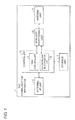
Fig. 1 is a block diagram illustrating a configuration of a main part of an RFID reader/writer according to an embodiment of the invention; -
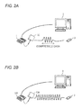
Fig. 2A is a view illustrating a configuration of the RFID reader/writer of the embodiment, andFig. 2B is a view illustrating a configuration of a conventional RFID reader/writer; -
Fig. 3 is a block diagram illustrating a configuration of a main part of an RFID tag according to an embodiment of the invention: -
Fig. 4 is a view illustrating a configuration of a memory of the RFID tag of the embodiment; -
Fig. 5 is a view illustrating a configuration of a memory of the RFID tag of the embodiment; -
Fig. 6 is a sequence diagram illustrating a processing flow of the embodiment; -
Fig. 7 is a sequence diagram illustrating a processing flow of the embodiment; -
Fig. 8 is an explanatory view of data compression in a data compression/decompression unit of the RFID reader/writer of the embodiment; -
Fig. 9 is an explanatory view of data compression in the data compression/decompression unit of the RFID reader/writer of the embodiment; -
Fig. 10 is a view illustrating an effect of a 0-1 inversion format in the data compression/decompression unit; and -
Fig. 11 is a view illustrating an effect of a 0-1 inversion format in the data compression/decompression unit. - Hereinafter, a preferred embodiment of the present invention will be described with reference to
Figs. 1 to 11 . An RFID reader/writer (tag communication apparatus) 1 according to an embodiment of the invention conducts wireless communication with anRFID tag 3 to read and write data. - In the embodiment, when the RFID reader/
writer 1 conducts wireless communication with theRFID tag 3, the data is transmitted to theRFID tag 3 while compressed, whereby an information amount of the transmit data is reduced to achieve shortening of a transmission time. - Because the compressed data is written in the
RFID tag 3, it is necessary to perform decoding compatible with a compression format in order to read the data written in theRFID tag 3. Therefore, security of the data written in theRFID tag 3 is improved. - A configuration of the embodiment will specifically be described with reference to
Fig. 2. Fig. 2A is a view illustrating a configuration of the RFID reader/writer 1 of the embodiment, andFig. 2B is a view illustrating a configuration of a conventional RFID reader/writer. As illustrated inFig. 2A , when the RFID reader/writer 1 receives the data to be written in theRFID tag 3 from a Personal Computer (PC) 2 that is of a high-order instrument, the RFID reader/writer 1 compresses the received data to convert the data into a format suitable to the transmission, and the RFID reader/writer 1 transmits the data to theRFID tag 3 through anantenna 130. - On the other hand, in the conventional configuration, as illustrated in
Fig. 2B , an RFID reader/writer 100 directly converts data, which is received from thePC 2 and written in theRFID tag 3, into a format suitable to the transmission to transmit the data to theRFID tag 3 through theantenna 130. - Therefore, in the embodiment, the data transmitted from the RFID reader/
writer 1 to theRFID tag 3 is compressed, so that the amount of data to be transmitted can be reduced to shorten the transmission time. - The RFID reader/
writer 1 of the embodiment will be described with reference toFig. 1 . As illustrated inFig. 1 , the RFID reader/writer 1 includes acontroller 10, astorage unit 11, a wireless processing unit (transmission unit) 12, anantenna unit 13, and an external I/F unit (data obtaining unit) 14. - The
controller 10 totally controls an operation of the RFID reader/writer 1. Thecontroller 10 includes a PC-based computer. The operation of the RFID reader/writer 1 is controlled by causing the computer to execute a control program. For example, the program recorded in a removable media such as a CD-ROM may be read in and executed by the computer, or the program installed in a hard disk may be read in and executed by the computer. Alternatively, the program is down-loaded through the external I/F unit 14 and installed in the hard disk, and the program may be read in and executed by the computer. - The
controller 10 also includes a tag controller (space information producing unit, empty space determining unit, space shortage information transmission unit) 21 and a data compression/decompression unit (data compression unit, data decompression unit, compressed data obtaining unit) 22. Thetag controller 21 transmits a predetermined command to theRFID tag 3 through thewireless processing unit 12 and theantenna unit 13 and processes a command received from theRFID tag 3. - More particularly, when the external I/
F unit 14 receives the data to be written in theRFID tag 3, thetag controller 21 makes a request for theRFID tag 3 to transmit file data. When obtaining the file data from theRFID tag 3, thetag controller 21 computes an address map from the file data to determine whether the data can be written in theRFID tag 3. When the data can be written in theRFID tag 3, thetag controller 21 produces file information (space information and compressed data space information) that is of data to be written in afile table area 505 with respect to the data to be written in theRFID tag 3, and thetag controller 21 transmits the file information to theRFID tag 3. When the data cannot be written in theRFID tag 3, thetag controller 21 transmits data (space shortage information) indicating that theRFID tag 3 has no space where the data is written to a high-order instrument (source device) of the RFID reader/writer 1 through the external I/F unit 14. The high-order instrument is a source of the data to be written in theRFID tag 3. - As used herein, the file data means data in which a storage space and stored information are correlated with each other in a
memory 35 of theRFID tag 3. The RFID reader/writer 1 can write plural pieces of data in theRFID tag 3 by producing the file data. - The data compression/
decompression unit 22 compresses the data, which is obtained through the external I/F unit 14 and written in theRFID tag 3. The data compression/decompression unit 22 computes a data length of the compressed data that is of the data after the compression, and the data compression/decompression unit 22 transmits the compressed data and the data length of the data to thewireless processing unit 12. The detailed data compression is described later. The data compression/decompression unit 22 obtains the compressed data, transmitted from theRFID tag 3 through theantenna unit 13 and thewireless processing unit 12, and decompresses the compressed data. When plural pieces of compressed data are written in theRFID tag 3, the data compression/decompression unit 22 computes a storage space for the desired compressed data from the file data, obtains the compressed data written in the storage space, and decompresses the compressed data. - The
storage unit 11 includes a nonvolatile storage device such as the hard disk. Examples of contents stored in thestorage unit 11 include the control program, an OS (operating system) program, various programs and various pieces of data. - The
wireless processing unit 12 converts the data, received from thecontroller 10, into a format suitable to wireless transmission to transmit the converted wireless signal to the outside through theantenna unit 13. Thewireless processing unit 12 also converts the wireless signal, received from the outside through the antenna unit 16, into the original format to transmit the converted data to thecontroller 10. Thewireless processing unit 12 includes an A/D (Analog-to-Digital) conversion circuit, a D/A (Digital-to-Analog) conversion circuit, a modulation/demodulation circuit, and an RF circuit. - The
antenna unit 13 transmits the wireless signal from thewireless processing unit 12 to the outside in the form of a radio wave, and theantenna unit 13 converts the radio wave received from the outside into the wireless signal to transmit the wireless signal to thewireless processing unit 12. Theantenna unit 13 includes theantenna 130 and an oscillation circuit. - The external I/
F unit 14 conducts communication with the external device such as the PC. USB (Universal Serial Bus), IEEE1394, and Ethernet (registered trademark) can be cited as an example of an interface standard of the external I/F unit 14. - A configuration of the
RFID tag 3 will be described with reference toFig. 3 . The usual RFID tag does not include a power supply such as a battery, but a circuit is operated by an electric power transmitted from the RFID reader/writer in the form of the radio wave, whereby the RFID tag conducts wireless communication with the RFID reader/writer. - As illustrated in
Fig. 3 , theRFID tag 3 includes anantenna unit 30 and awireless communication IC 31. - The
antenna unit 30 receives the radio wave from the RFID reader/writer 1 as a power source used to operate thewireless communication IC 31. Theantenna unit 30 converts the radio wave received from the RFID reader/writer 1 into the wireless signal to transmit the wireless signal to thewireless communication IC 31, and theantenna unit 30 converts the wireless signal from thewireless communication IC 31 into the radio wave to transmit the radio wave to the RFID reader/writer 1. Theantenna unit 30 includes an antenna and an oscillation circuit. - Based on the signal received from the RFID reader/
writer 1 through theantenna unit 30, thewireless communication IC 31 stores the data from the RFID reader/writer 1 or transmits the stored data to the RFID reader/writer 1 through theantenna unit 30. As illustrated inFig. 5 , thewireless communication IC 31 includes apower supply unit 32, awireless processing unit 33, a controller 34, and amemory 35. - In the
power supply unit 32, a rectifying circuit rectifies an inductive voltage, which is generated by theantenna unit 30 receiving the radio wave, a power supply circuit adjusts the generated voltage to a predetermined voltage, and then the voltage is supplied to each unit of thewireless communication IC 31. Thepower supply unit 32 includes a bridge diode and a voltage adjusting capacitor. - The
wireless processing unit 33 converts the wireless signal received from the outside through theantenna unit 30 into the original format to transmit the converted data to the controller 34, and thewireless processing unit 33 converts the data received from the controller 34 into the format suitable to the wireless transmission to transmit the converted wireless signal to the outside through theantenna unit 30. Thewireless processing unit 33 includes an A/D (Analog-to-Digital) conversion circuit, a D/A (Digital-to-Analog) conversion circuit, a modulation/demodulation circuit, and an RF circuit. - The controller 34 totally controls an operation of the
wireless communication IC 31. The controller 34 includes a logic operation circuit and a register, and the controller 34 acts as a computer. The operation is controlled by causing the computer to execute a control program. For example, the program installed in thememory 35 such as a ROM (Read Only Memory) may be read in and executed by the computer. Alternatively, the program is down-loaded from the RFID reader/writer 1 through theantenna unit 30 and thewireless processing unit 33 and installed in thememory 35, and the program may be read in and executed by the computer. - Based on the data received from the RFID reader/
writer 1 through theantenna unit 30 and thewireless processing unit 33. the controller 34 stores the data from the RFID reader/writer 1 in thememory 35, and reads the data stored in thememory 35 to transmit the data to the RFID reader/writer 1 through thewireless processing unit 33 and theantenna unit 30. - The
memory 35 includes a semiconductor memory such as the ROM, an SRAM (Static RAM), and an FeRAM (ferroelectric memory). Examples of contents stored in thememory 35 include the above described control program, various programs, and various pieces of data. Desirably a nonvolatile memory such as the ROM and a low-power-consumption memory such as the SRAM and the FeRAM are used, because the radio wave transmitted from the RFID reader/writer is used as the power source in thewireless communication IC 31. - A structure of the
memory 35 of theRFID tag 3 will be described below with reference toFig. 4 andFig. 5 .Fig. 4 illustrates a structure of thememory 35 when one kind of the data is stored, andFig. 5 illustrates a structure of thememory 35 when plural kinds of the pieces of data are stored. - As illustrated in
Fig. 4 , when the one kind of the data is stored (written) in thememory 35, thememory 35 has a structure including a datalength write area 401 in which a data length of the stored data is written and a compresseddata write area 402 in which the compressed data is written. Because the data to be written is compressed, the data length of the data to be written becomes variable. Therefore, possibly the compressed data cannot be read unless the data length of the compressed data is written. - As illustrated in
Fig. 5 , when the plural kinds of the pieces of data are stored in thememory 35, thememory 35 has a structure including afile table area 505 in which a file name, a file size, and a file storage starting address of each of the pieces of data to be written are written and a compresseddata write area 506 in which the compressed data is written. This is because, when the plural kinds of the pieces of data are stored, the data cannot be read unless information indicating where the data is written exists. -
Fig. 5 illustrates an example in which logdata 501a of aninspection process 1, logdata 502a of aninspection process 2, and logdata 503a of aninspection process 3 are written in theRFID tag 3 as the plural kinds of the pieces of data. As illustrated inFig. 5 , when the pieces of data are stored in theRFID tag 3, the pieces of data are compressed to produce pieces of file information indicating file names, file sizes, and file storage starting addresses of compressed data 501b of theinspection process 1, compressed data 502b of theinspection process 2, andcompressed data 503b of theinspection process 3. The file storage starting address is used when the compressed data is written in the compresseddata write area 506, Then the produced pieces of file information are written in thefile table area 505 of thememory 35. - Specifically, the file name, file size, and file storage starting address, used in writing the compressed data in the compressed
data write area 506, of the compressed data 501 b of theinspection process 1 are written in a datainformation storage area 511 of theinspection process 1 in thefile table area 505. Similarly, the file name, file size, and file storage starting address, used in writing the compressed data in the compresseddata write area 506, of the compressed data 502b of theinspection process 2 are written in a datainformation storage area 512 of theinspection process 2 in thefile table area 505. Similarly, the file name, file size, and file storage starting address, used in writing the compressed data in the compresseddata write area 506, of thecompressed data 503b of theinspection process 3 are written in a datainformation storage area 513 of theinspection process 3 in thefile table area 505. - The compressed data 501 b of the
inspection process 1, the compressed data 502b of theinspection process 2, and thecompressed data 503b of theinspection process 3 are written in position, indicated by the file storage starting addresses thereof, in the compresseddata write area 506. - A processing flow of the embodiment will be described below with reference to
Fig. 6 andFig. 7 .Fig. 6 illustrates a processing flow when the one kind of the data is written in theRFID tag 3, andFig. 7 illustrates a processing flow when the plural kinds of the pieces of data are written in theRFID tag 3. - As illustrated in
Fig. 6 , when the one kind of the data is written in the RFID tag the external I/F unit 14 of the RFID reader/writer 1 obtains the data to be written in theRFID tag 3 from the high-order instrument (data obtaining step in S601). The data compression/decompression unit 22 compresses the data obtained by the external I/F unit 14 (data compression step in S602). The data compression/decompression unit 22 computes the data length of the compressed data that is of the data after the compression (S603). The computed data length is transmitted to theRFID tag 3 through thewireless processing unit 12 and the antenna unit 13 (transmission step in S604). TheRFID tag 3 writes the received data length in the memory 35 (S605). The RFID reader/writer 1 transmits the compressed data compressed by the data compression/decompression unit 22 to the RAID tag 3 (S606). When receiving the compressed data, theRFID tag 3 writes the compressed data in the compresseddata write area 402 of the memory 35 (S607). Therefore, the processing of writing the one kind of the data to be written in theRFID tag 3 is ended. - The processing flow in writing the plural kinds of the pieces of data in the
RFID tag 3 will be described below with reference toFig. 7 , - As illustrated in
Fig. 7 , the external I/F unit 14 of the RFID reader/writer 1 obtains the plural kinds of the pieces of data to be written in the RFID tag 3 (S701). Thetag controller 21 makes a request for theRFID tag 3 to transmit the file table (S702). TheRFID tag 3 transmits the file table to the RFID reader/writer 1 in response to the request (S703). When obtaining the file table (S704), thetag controller 21 computes the address map indicating the position where the data is written in the memory 35 (S705). - The data compression/
decompression unit 22 compresses the plural kinds of the pieces of data obtained by the external I/F unit 14 (S706), and the data compression/decompression unit 22 computes the data length of each of the pieces of data that are of the pieces of data after the compression (S707). Thetag controller 21 determines whether the compressed data can be written in thememory 35 from the computed address map and data length (S708). When determining that the compressed data can be written in the memory 35 (YES in S708), thetag controller 21 produces the file information that is of the data written in thefile table area 505 of the memory 35 (S710). Thetag controller 21 transmits the produced file information to the RFID tag 3 (S711). TheRFID tag 3 writes the received file information infile table area 505, of the memory 35 (S712). The RFID reader/writer 1 transmits the pieces of compressed data to the RFID tag 3 (S713). TheRFID tag 3 writes the received pieces of compressed data to the compressed data writearea 506 of the memory 35 (S714). - On the other hand, when determining that the compressed data cannot be written in the memory 35 (NO in S708), the
tag controller 21 transmits an address over error indicating that the compressed data cannot be written in theRFID tag 3 to the high-order instrument, which is of the source of the data to be written in theRFID tag 3, through the external I/F unit 14 (S709). Therefore, the processing of writing the plural kinds of the pieces of data to be written in theRFID tag 3 is ended. - Examples of the data compression/conversion in the data compression/
decompression unit 22 will be described with reference toFig. 8 to Fig. 11 .Fig. 8 is a view illustrating the case where the data is compressed in an LZH format, andFig. 9 to Fig. 11 are views illustrating the case where the data is converted in a compression format (hereinafter referred to as a "0-1" inversion format) in which "0" and "1" are inverted, - The case where the data is compressed in the LZH format will be described below. In
Fig. 8 ,data 801 illustrates the state before the data is compressed, anddata 802 illustrates the state after the data is compressed in the LZH format. Thedata 801 has the data amount of 512 bytes before the compression, and thedata 802 has the data amount of 68 bytes after the compression. The data amount can be reduced by about 87% by compressing the data in the LZH format. Therefore, the communication time between the RFID reader/writer 1 and theRFID tag 3 can be shortened, and the improvement of memory usage can be achieved in theRFID tag 3. - The case where the data is converted in the 0-1 inversion format will be described below. In the 0-1 inversion format, the numbers of appearance times of "0" and "1" are computed in a bit string of the data that becomes the conversion target, the data is directly used when the number of appearance times of "0" is more than that of "1", and the data in which "0" and "1" are replaced with each other is used when the number of appearance times of "1" is more than that of "0". In the embodiment, the data is converted in the 0-1 inversion format in units (16 bits) in which the command is transmitted from the RFID reader/
writer 1 to theRF1D tag 3. The 0-1 inversion format can be applied when the communication between the RFID reader/writer and theRFID tag 3 is conducted in a UHF band. - In
Fig. 9A ,data 901 illustrates the state before the data is converted, anddata 902 illustrates the state after the data is converted in the 0-1 inversion format.Fig. 9B illustrates a structure of thememory 35 when the data is converted in the 0-1 inversion format As illustrated inFig. 9B , when the data is converted in the 0-1 inversion format, thememory 35 includes a converteddata write area 903 in which converted data is written and a conversion informationflag write area 904 in which the data indicating conversion information is written. A conversion information flag is written pursuant to a write protect method of an HF (High Frequency) instrument. - When the data is converted in the 0-1 inversion format, although both in the
data 901 before the conversion and thedata 902 after the conversion have the same data amount of 512 bytes, the communication time between the RFID reader/writer 1 and theRFID tag 3 is improved by about 10%. The reason will be described with reference toFig, 10 and FIG. 11. Fig. 10 illustrates symbol times of the data "0" and data "1" in the UHF band. As illustrated inFig. 10 , the data "0" has the symbol time of 1 Tari (Type A Reference Interval) while the data "1" has the symbol time of 1.5 to 2.0 Tari. Therefore, it is found that the data "1" is shorter than the data "0" in the transmission time. -
Fig. 11 illustrates transmission times of the data "0" and data "1'' in an LF band. As illustrated inFig. 11 , the data "0" has a frequency of 134.2 KHz and the transmission time of 119,9 µs, while the data "1" has the frequency of 123.2 KHz and the transmission time of 129.2 µs. Therefore, it is found that the data "0" is shorter than the data "1" in the transmission time. - As described above, the data is converted in the 0-1 inversion format, and the data is converted into the data in which "0" and "1" are replaced with each other when the data is directly used when the number of appearance times of "1" is more than that of "0", so that the data transmission time (the time necessary to transmit the data from the RFID reader/
writer 1 to theRFID tag 3 and the time necessary to receive the data from theRFID tag 3 to the RFID reader/writer 1) can be shortened. Because a computing processing load is tighter than that of the compression/decompression method, the data transmission time can be shortened in this regard. - The 0-1 inversion format is not limited to the data "0" and data "1", but the 0-1 inversion format can be applied when information transmission time necessary to transmit one of pieces of information is different from information transmission time necessary to transmit the other piece of information.
- The RFID reader/
writer 1 that can convert the data in the 0-1 inversion format and the RFID reader/writer 1 that cannot convert the data in the 0-1 inversion format are disposed in the processes, and the data can be converted in the 0-1 inversion format only in the process in which the communication between the RFID reader/writer 1 and theRFID tag 3 is condusted, which allows the 0-1 inversion format to be used in process management. - When the unique data compression method is adopted, the compressed data cannot be read and decompressed by an apparatus except the apparatus that compresses the data. Therefore, safety of the data written in the
RFID tag 3 is enhanced to improve security in the communication system between the RFID reader/writer 1 and theRFID tag 3. - When a transmission rate from the RAID reader/
writer 1 to theRFID tag 3 is different from a reception rate from theRFID tag 3 to the RFID reader/writer 1, the transmission/reception time is computed from the transmission rate and the reception rate, an information transmission/reception time necessary to transmit and receive one of pieces of information is compared to an information transmission/reception time necessary to transmit and receive the other piece of information, and the data may be converted so as to achieve the shorter transmission/reception time. - The invention is not limited to the embodiment, but various modifications can be made without departing from the scope of the invention. That is, an embodiment obtained by a combination of technical means appropriately changed within a range of claims is also included in the technical scope of the invention.
- Finally, each block of the RFID reader/
writer 1 andRFID tag 3, particularly the controller 10 (tag controller 21, data compression/decompression unit 22) andwireless processing unit 12 of the RFID reader/writer 1 and the controller 34 of theRFID tag 3 may be implemented by a logic circuit formed on an integrated circuit (IC chip) in a hardware manner or may be implemented in a software manner using a CPU (Central Processing Unit). - In the latter, the RFID reader/
writer 1 and theRFID tag 3 include the CPU that executes a command of a control program implementing each function, the ROM (Read Only Memory) in which the program is stored, the RAM (Random Access Memory) in which the program is expanded, and the storage device (recording medium) such as a memory in which the program and various pieces of data are stored. Program codes (an executable format program, an intermediate code program, and a source program) of the control programs that are of the software implementing the functions in the RFID reader/writer 1 andRFID tag 3 are recorded in the computer-readable recording medium, the recording medium is supplied to the RFID reader/writer 1 and theRFID tag 3, and the computers (or the CPU or MPU (Microprocessor Unit)) of the RFID reader/writer 1 andRFID tag 3 read and execute the program code recorded in the recording medium, which allows the object of the invention to be achieved. - Examples of the recording medium include tape system such as magnetic tape and cassette tape, disk systems including magnetic disks such as floppy disk (registered trademark) and a hard disk and optical disks such as a CD-ROM (Compact Disc Read Only Memory), an MO (Magneto-Optical) an MD (Mini Disc), a DVD (Digital Versatile Disc), and a CD-R (CD Recordable), card systems such as an IC card (including a memory card) and an optical card, semiconductor memory systems such as a mask ROM, an EPROM (Erasable Programmable Read Only Memory), an EEPROM (Electrically Erasable Programmable Read Only Memory) and a flash ROM, and logic circuits such as a PLD (Programmable Logic Device) and an FPGA (Field Programmable Gate Array).
- The RFID reader/
writer 1 and theRFID tag 3 are configured to be able to be connected to a communication network, and the program code may be supplied through the communication network. There is no particular limitation to the communication network as long as the program code can be transmitted through the communication network. Examples of the communication network include the Internet, an intranet, an extranet, a LAN (Local Area Network), an ISDN (integrated Services Digital Network), a VAN (Value-Added Network), a CATV (Community Antenna Television), a virtual private network, a telephone line network, a mobile communication network, and a satellite communication network. A transmission medium constituting the communication network is not limited to a specific configuration or a specific kind as long as the transmission medium can transmit the program code. Examples of the transmission medium include wired lines such as IEEE (Institute of Electrical and Electronic Engineers) 1394, a USB, a power-line carrier, a cable TV line, a telephone line, and an ADSL (Asynchronous Digital Subscriber Loop) line and wireless lines such as infrared ray such as IrDA (Infrared Data Association) and a remote controller, Bluetooth (registered trademark),IEEE - Because the data can be transmitted to the RFID tag while compressed, the invention is suitable to the tag communication apparatus that transmits the information having the large data amount to the RFID tag.
Claims (8)
- A tag communication apparatus adapted to conduct wireless communication with an RFID tag (3) through a radio wave, the tag communication apparatus comprising:a data obtaining unit (14) adapted to obtain transmit data transmitted to the RFID tag (3);a data compression unit adapted to compress at least part of the transmit data obtained by the data obtaining unit (14) and to output compressed data; anda transmission unit (12) adapted to transmit the part of compressed data, which is compressed and output by the data compression unit, to the RFID tag (3).
- The tag communication apparatus according to claim 1, further comprising:a space information producing unit (21) adapted to produce space information in which a storage space in a storage unit (11) of the RFID tag (3) is correlated with stored information,wherein the data obtaining unit (14) is adapted to obtain the plurality of pieces of transmit data,the data compression unit is adapted to compress the plurality of pieces of transmit data obtained by the data obtaining unit (14) and to output a plurality of pieces of compressed data,the space information producing unit (21) is adapted to produce compressed data space information about that which compressed data in the plurality of pieces of compressed data is correlated with the space where the compressed data is stored in the storage unit (11) of the RFID tag (3), andthe transmission unit (12) is adapted to transmit the plurality of pieces of compressed data output from the data compression unit and the compressed data space information produced by the space information producing unit (21),
- The tag communication apparatus according to claim 2, further comprising:an empty space determining unit (21) adapted to determine whether an empty space where the compressed data can be stored exists in the storage unit (11) of the RFID tag (3); anda space shortage information transmission unit (21) adapted to transmit space shortage information indicating no empty space to a source device of the transmit data obtained by the data obtaining unit (14) when the empty space determining unit (21) determines that the empty space does not exist.
- The tag communication apparatus as in any one of claims 1 to 3,
wherein in a communication format in which one of bit information transmission times necessary to transmit pieces of bit information constituting a data bit string is longer than the other bit information transmission time,
the data compression unit is adapted to count the number of appearance times of bits of the data bit string in the transmit data,
the data compression unit is adapted to directly output the transmit data when the number of appearance times of the bit having the shorter bit information transmission time is more than that of the bit having the longer bit information transmission time, and
the data compression unit is adapted to produce and output converted data in which the bits of the data bit string in the transmit data are replaced with each other when the number of appearance times of the bit having the longer bit information transmission time is more than that of the bit having the shorter bit information transmission time. - The tag communication apparatus as in any one of claims 1 to 4, further comprising:a compressed data obtaining unit (22) adapted to obtain the compressed data transmitted from the transmission unit (12) to the RFID tag (3); anda data decompression unit (22) adapted to decompress the compressed data obtained by the compressed data obtaining unit (22).
- The tag communication apparatus according to claim 5, wherein the compressed data obtaining unit (22) is adapted to obtain desired compressed data using the compressed data space information when the compressed data space information exists.
- A method for controlling a tag communication apparatus that conducts wireless communication with an RFID tag (3) through a radio wave, the method comprising the steps of:obtaining transmit data transmitted to the RFID tag (3);compressing at least part of the transmit data obtained in the data obtaining step and outputting compressed data; andtransmitting the part of compressed data, which is compressed and output by the data compression step, to the RFID tag (3).
- A tag communication apparatus control program that operates a tag communication apparatus to conduct wireless communication with an RFID tag (3) through a radio wave, the program causing a computer to execute the steps of:obtaining transmit data transmitted to the RFID tag (3):compressing at least part of the transmit data obtained in the data obtaining step and outputting compressed data; andtransmitting the part of compressed data, which is compressed and output by the data compression step, to the RFID tag (3).
Applications Claiming Priority (1)
| Application Number | Priority Date | Filing Date | Title |
|---|---|---|---|
| JP2010058547A JP5234030B2 (en) | 2010-03-15 | 2010-03-15 | Tag communication device, tag communication device control method, and tag communication device control program |
Publications (2)
| Publication Number | Publication Date |
|---|---|
| EP2367136A1 true EP2367136A1 (en) | 2011-09-21 |
| EP2367136B1 EP2367136B1 (en) | 2016-01-27 |
Family
ID=43928102
Family Applications (1)
| Application Number | Title | Priority Date | Filing Date |
|---|---|---|---|
| EP11153764.3A Active EP2367136B1 (en) | 2010-03-15 | 2011-02-09 | Tag communication apparatus, tag communication apparatus control method, and tag communication apparatus control program |
Country Status (4)
| Country | Link |
|---|---|
| US (1) | US8519829B2 (en) |
| EP (1) | EP2367136B1 (en) |
| JP (1) | JP5234030B2 (en) |
| CN (1) | CN102194139B (en) |
Cited By (1)
| Publication number | Priority date | Publication date | Assignee | Title |
|---|---|---|---|---|
| ITMO20110268A1 (en) * | 2011-10-25 | 2013-04-26 | Weflex Sociea A Responsabilita Li Mitata | EQUIPMENT FOR MANAGEMENT AND CONTROL OF SAILING OR SIMILAR BOATS |
Families Citing this family (12)
| Publication number | Priority date | Publication date | Assignee | Title |
|---|---|---|---|---|
| KR101337302B1 (en) * | 2011-09-21 | 2013-12-05 | 한국전자통신연구원 | Inducement apparatus, method for controlling inducement apparatus, inducement system |
| US9024730B2 (en) * | 2012-09-04 | 2015-05-05 | Honeywell International Inc. | Standby activation |
| CN103442009A (en) * | 2013-08-30 | 2013-12-11 | 苏州跨界软件科技有限公司 | File transmission method based on NFC |
| CN103412955B (en) * | 2013-09-01 | 2021-08-17 | 湖南人文科技学院 | A RFID Data Compression Method |
| JP6314473B2 (en) | 2013-12-24 | 2018-04-25 | オムロン株式会社 | Image display processing apparatus and display processing program |
| JP2015121939A (en) | 2013-12-24 | 2015-07-02 | オムロン株式会社 | RFID reader / writer and diagnostic processing program |
| CN105389865B (en) * | 2014-09-05 | 2018-05-25 | 深圳光启智能光子技术有限公司 | Shorten the digital signal method of sending and receiving and mobile terminal of sending time |
| JP6746508B2 (en) * | 2017-01-04 | 2020-08-26 | オムロン株式会社 | User terminal device and data transmission method |
| CN109120272B (en) * | 2018-07-16 | 2021-09-28 | 南京航空航天大学 | RFID tag data compression method for discrete manufacturing workshop |
| CN113658631B (en) * | 2021-10-20 | 2022-01-25 | 成都凯路威电子有限公司 | Hybrid UHFRFID memory and information storage method |
| CN116843926A (en) * | 2023-06-15 | 2023-10-03 | 邦邦汽车销售服务(北京)有限公司 | Supply chain traceability method and related equipment for auto parts based on data processing |
| CN118656769B (en) * | 2024-08-21 | 2024-10-22 | 大连地铁科技有限公司 | A data processing method and system for AFC reader/writer |
Citations (6)
| Publication number | Priority date | Publication date | Assignee | Title |
|---|---|---|---|---|
| EP1398731A1 (en) * | 2002-09-09 | 2004-03-17 | Eastman Kodak Company | Virtual annotation of a recording on an archival media |
| JP2007094873A (en) | 2005-09-29 | 2007-04-12 | Fujifilm Corp | Radio tag information hiding method, radio tag device, and radio tag information hiding system |
| US20070122941A1 (en) * | 2005-11-29 | 2007-05-31 | Michihiro Ota | Terminal device communicating with contact-less IC media, and a communication method performed in the terminal device |
| JP2007213115A (en) | 2006-02-07 | 2007-08-23 | Brother Ind Ltd | RFID circuit element, RFID tag information reading device, tag label producing device |
| WO2007139969A2 (en) * | 2006-05-26 | 2007-12-06 | Symbol Technologies, Inc. | Data format for efficient encoding and access of multiple data items in rfid tags |
| JP2009015606A (en) | 2007-07-05 | 2009-01-22 | Brother Ind Ltd | RFID tag circuit element and RFID tag communication system |
Family Cites Families (11)
| Publication number | Priority date | Publication date | Assignee | Title |
|---|---|---|---|---|
| US4829421A (en) * | 1984-11-05 | 1989-05-09 | S. C. Yuter, J.S.D. | Data transfer regulating system for recording data at a varying recording |
| JPH09162748A (en) * | 1995-12-01 | 1997-06-20 | Fujitsu Ltd | Data encoding method, data decoding method, data compression device, data decompression device, and data compression / decompression system |
| JP2005063038A (en) * | 2003-08-08 | 2005-03-10 | Sony Corp | Data processing apparatus, method thereof, program thereof and recording medium |
| EP2894590B1 (en) * | 2005-09-29 | 2020-03-04 | Symbol Technologies, LLC | Truncation, compression, and encryption of RFID tag communications |
| CN100527159C (en) * | 2005-10-31 | 2009-08-12 | 深圳华为通信技术有限公司 | Storage card and terminal equipment combining storage card |
| JP4456554B2 (en) * | 2005-10-31 | 2010-04-28 | 富士通株式会社 | Data compression method and compressed data transmission method |
| US7532232B2 (en) * | 2006-04-20 | 2009-05-12 | Cisco Technology, Inc. | System and method for single action initiation of a video conference |
| US20080316521A1 (en) * | 2007-06-21 | 2008-12-25 | Philippe Lesage | Systems and methods for managing facsimile documents |
| KR100964374B1 (en) * | 2007-12-17 | 2010-06-17 | 한국전자통신연구원 | Apparatus and method for memory identification tag |
| US8483311B2 (en) * | 2008-03-06 | 2013-07-09 | Nokia Corporation | Method, apparatus and computer program product for providing a data encoding/decoding scheme |
| US20100194533A1 (en) * | 2009-01-30 | 2010-08-05 | Sullivan Henry W | Method and apparatus for encoding railroad ties and other railroad track components |
-
2010
- 2010-03-15 JP JP2010058547A patent/JP5234030B2/en active Active
-
2011
- 2011-02-09 EP EP11153764.3A patent/EP2367136B1/en active Active
- 2011-02-14 US US13/026,766 patent/US8519829B2/en active Active
- 2011-02-21 CN CN201110044098.7A patent/CN102194139B/en active Active
Patent Citations (6)
| Publication number | Priority date | Publication date | Assignee | Title |
|---|---|---|---|---|
| EP1398731A1 (en) * | 2002-09-09 | 2004-03-17 | Eastman Kodak Company | Virtual annotation of a recording on an archival media |
| JP2007094873A (en) | 2005-09-29 | 2007-04-12 | Fujifilm Corp | Radio tag information hiding method, radio tag device, and radio tag information hiding system |
| US20070122941A1 (en) * | 2005-11-29 | 2007-05-31 | Michihiro Ota | Terminal device communicating with contact-less IC media, and a communication method performed in the terminal device |
| JP2007213115A (en) | 2006-02-07 | 2007-08-23 | Brother Ind Ltd | RFID circuit element, RFID tag information reading device, tag label producing device |
| WO2007139969A2 (en) * | 2006-05-26 | 2007-12-06 | Symbol Technologies, Inc. | Data format for efficient encoding and access of multiple data items in rfid tags |
| JP2009015606A (en) | 2007-07-05 | 2009-01-22 | Brother Ind Ltd | RFID tag circuit element and RFID tag communication system |
Cited By (1)
| Publication number | Priority date | Publication date | Assignee | Title |
|---|---|---|---|---|
| ITMO20110268A1 (en) * | 2011-10-25 | 2013-04-26 | Weflex Sociea A Responsabilita Li Mitata | EQUIPMENT FOR MANAGEMENT AND CONTROL OF SAILING OR SIMILAR BOATS |
Also Published As
| Publication number | Publication date |
|---|---|
| CN102194139B (en) | 2014-02-26 |
| US20110221571A1 (en) | 2011-09-15 |
| EP2367136B1 (en) | 2016-01-27 |
| JP5234030B2 (en) | 2013-07-10 |
| US8519829B2 (en) | 2013-08-27 |
| JP2011193299A (en) | 2011-09-29 |
| CN102194139A (en) | 2011-09-21 |
Similar Documents
| Publication | Publication Date | Title |
|---|---|---|
| EP2367136B1 (en) | Tag communication apparatus, tag communication apparatus control method, and tag communication apparatus control program | |
| US8665073B2 (en) | Truncation, compression, and encryption of RFID tag communications | |
| KR100912076B1 (en) | Apparatus and method for Integrated Reader and Tag | |
| EP2097838B1 (en) | A method for storing data in a rfid transponder | |
| CN101675428B (en) | Method and device for storing/reading data in storage array of a transponder | |
| US11170385B2 (en) | RFID-based genuine product certification service system and method employing code update algorithm for forgery prevention | |
| CN101159025B (en) | RFID tag reader and method | |
| US20110016373A1 (en) | System, method, and apparatus for data communication | |
| US20060253415A1 (en) | Data-defined communication device | |
| US8698599B2 (en) | Reader/writer, communication processing device, communication processing method, data management system and communication system | |
| US11875217B2 (en) | Information processing apparatus, information processing terminal apparatus, and information processing method | |
| JP2007221347A (en) | Communication device | |
| KR100964036B1 (en) | RF card reading method using reader and reader | |
| KR101296401B1 (en) | RFID Tag for Managing Items | |
| KR101267285B1 (en) | Apparatus and method for processing information | |
| AU2011253949A1 (en) | Truncation, compression and encryption of RFID tag communications | |
| KR20150066508A (en) | Method for Encoding and Outputting Data |
Legal Events
| Date | Code | Title | Description |
|---|---|---|---|
| PUAI | Public reference made under article 153(3) epc to a published international application that has entered the european phase |
Free format text: ORIGINAL CODE: 0009012 |
|
| AK | Designated contracting states |
Kind code of ref document: A1 Designated state(s): AL AT BE BG CH CY CZ DE DK EE ES FI FR GB GR HR HU IE IS IT LI LT LU LV MC MK MT NL NO PL PT RO RS SE SI SK SM TR |
|
| AX | Request for extension of the european patent |
Extension state: BA ME |
|
| 17P | Request for examination filed |
Effective date: 20120321 |
|
| 17Q | First examination report despatched |
Effective date: 20140327 |
|
| GRAP | Despatch of communication of intention to grant a patent |
Free format text: ORIGINAL CODE: EPIDOSNIGR1 |
|
| RIC1 | Information provided on ipc code assigned before grant |
Ipc: G06K 7/10 20060101ALI20150624BHEP Ipc: G06K 7/00 20060101AFI20150624BHEP |
|
| INTG | Intention to grant announced |
Effective date: 20150714 |
|
| GRAS | Grant fee paid |
Free format text: ORIGINAL CODE: EPIDOSNIGR3 |
|
| GRAA | (expected) grant |
Free format text: ORIGINAL CODE: 0009210 |
|
| AK | Designated contracting states |
Kind code of ref document: B1 Designated state(s): AL AT BE BG CH CY CZ DE DK EE ES FI FR GB GR HR HU IE IS IT LI LT LU LV MC MK MT NL NO PL PT RO RS SE SI SK SM TR |
|
| REG | Reference to a national code |
Ref country code: GB Ref legal event code: FG4D |
|
| REG | Reference to a national code |
Ref country code: CH Ref legal event code: EP |
|
| REG | Reference to a national code |
Ref country code: AT Ref legal event code: REF Ref document number: 773006 Country of ref document: AT Kind code of ref document: T Effective date: 20160215 |
|
| REG | Reference to a national code |
Ref country code: IE Ref legal event code: FG4D |
|
| REG | Reference to a national code |
Ref country code: DE Ref legal event code: R096 Ref document number: 602011022938 Country of ref document: DE |
|
| REG | Reference to a national code |
Ref country code: LT Ref legal event code: MG4D |
|
| PG25 | Lapsed in a contracting state [announced via postgrant information from national office to epo] |
Ref country code: BE Free format text: LAPSE BECAUSE OF NON-PAYMENT OF DUE FEES Effective date: 20160229 |
|
| REG | Reference to a national code |
Ref country code: NL Ref legal event code: MP Effective date: 20160127 |
|
| REG | Reference to a national code |
Ref country code: AT Ref legal event code: MK05 Ref document number: 773006 Country of ref document: AT Kind code of ref document: T Effective date: 20160127 |
|
| PG25 | Lapsed in a contracting state [announced via postgrant information from national office to epo] |
Ref country code: NL Free format text: LAPSE BECAUSE OF FAILURE TO SUBMIT A TRANSLATION OF THE DESCRIPTION OR TO PAY THE FEE WITHIN THE PRESCRIBED TIME-LIMIT Effective date: 20160127 |
|
| PG25 | Lapsed in a contracting state [announced via postgrant information from national office to epo] |
Ref country code: IT Free format text: LAPSE BECAUSE OF FAILURE TO SUBMIT A TRANSLATION OF THE DESCRIPTION OR TO PAY THE FEE WITHIN THE PRESCRIBED TIME-LIMIT Effective date: 20160127 Ref country code: HR Free format text: LAPSE BECAUSE OF FAILURE TO SUBMIT A TRANSLATION OF THE DESCRIPTION OR TO PAY THE FEE WITHIN THE PRESCRIBED TIME-LIMIT Effective date: 20160127 Ref country code: ES Free format text: LAPSE BECAUSE OF FAILURE TO SUBMIT A TRANSLATION OF THE DESCRIPTION OR TO PAY THE FEE WITHIN THE PRESCRIBED TIME-LIMIT Effective date: 20160127 Ref country code: NO Free format text: LAPSE BECAUSE OF FAILURE TO SUBMIT A TRANSLATION OF THE DESCRIPTION OR TO PAY THE FEE WITHIN THE PRESCRIBED TIME-LIMIT Effective date: 20160427 Ref country code: GR Free format text: LAPSE BECAUSE OF FAILURE TO SUBMIT A TRANSLATION OF THE DESCRIPTION OR TO PAY THE FEE WITHIN THE PRESCRIBED TIME-LIMIT Effective date: 20160428 Ref country code: FI Free format text: LAPSE BECAUSE OF FAILURE TO SUBMIT A TRANSLATION OF THE DESCRIPTION OR TO PAY THE FEE WITHIN THE PRESCRIBED TIME-LIMIT Effective date: 20160127 |
|
| PG25 | Lapsed in a contracting state [announced via postgrant information from national office to epo] |
Ref country code: LV Free format text: LAPSE BECAUSE OF FAILURE TO SUBMIT A TRANSLATION OF THE DESCRIPTION OR TO PAY THE FEE WITHIN THE PRESCRIBED TIME-LIMIT Effective date: 20160127 Ref country code: PL Free format text: LAPSE BECAUSE OF FAILURE TO SUBMIT A TRANSLATION OF THE DESCRIPTION OR TO PAY THE FEE WITHIN THE PRESCRIBED TIME-LIMIT Effective date: 20160127 Ref country code: RS Free format text: LAPSE BECAUSE OF FAILURE TO SUBMIT A TRANSLATION OF THE DESCRIPTION OR TO PAY THE FEE WITHIN THE PRESCRIBED TIME-LIMIT Effective date: 20160127 Ref country code: AT Free format text: LAPSE BECAUSE OF FAILURE TO SUBMIT A TRANSLATION OF THE DESCRIPTION OR TO PAY THE FEE WITHIN THE PRESCRIBED TIME-LIMIT Effective date: 20160127 Ref country code: PT Free format text: LAPSE BECAUSE OF FAILURE TO SUBMIT A TRANSLATION OF THE DESCRIPTION OR TO PAY THE FEE WITHIN THE PRESCRIBED TIME-LIMIT Effective date: 20160527 Ref country code: SE Free format text: LAPSE BECAUSE OF FAILURE TO SUBMIT A TRANSLATION OF THE DESCRIPTION OR TO PAY THE FEE WITHIN THE PRESCRIBED TIME-LIMIT Effective date: 20160127 Ref country code: LT Free format text: LAPSE BECAUSE OF FAILURE TO SUBMIT A TRANSLATION OF THE DESCRIPTION OR TO PAY THE FEE WITHIN THE PRESCRIBED TIME-LIMIT Effective date: 20160127 Ref country code: IS Free format text: LAPSE BECAUSE OF FAILURE TO SUBMIT A TRANSLATION OF THE DESCRIPTION OR TO PAY THE FEE WITHIN THE PRESCRIBED TIME-LIMIT Effective date: 20160527 |
|
| REG | Reference to a national code |
Ref country code: CH Ref legal event code: PL |
|
| REG | Reference to a national code |
Ref country code: DE Ref legal event code: R097 Ref document number: 602011022938 Country of ref document: DE |
|
| PG25 | Lapsed in a contracting state [announced via postgrant information from national office to epo] |
Ref country code: DK Free format text: LAPSE BECAUSE OF FAILURE TO SUBMIT A TRANSLATION OF THE DESCRIPTION OR TO PAY THE FEE WITHIN THE PRESCRIBED TIME-LIMIT Effective date: 20160127 Ref country code: EE Free format text: LAPSE BECAUSE OF FAILURE TO SUBMIT A TRANSLATION OF THE DESCRIPTION OR TO PAY THE FEE WITHIN THE PRESCRIBED TIME-LIMIT Effective date: 20160127 Ref country code: CH Free format text: LAPSE BECAUSE OF NON-PAYMENT OF DUE FEES Effective date: 20160229 Ref country code: MC Free format text: LAPSE BECAUSE OF FAILURE TO SUBMIT A TRANSLATION OF THE DESCRIPTION OR TO PAY THE FEE WITHIN THE PRESCRIBED TIME-LIMIT Effective date: 20160127 Ref country code: LI Free format text: LAPSE BECAUSE OF NON-PAYMENT OF DUE FEES Effective date: 20160229 |
|
| PG25 | Lapsed in a contracting state [announced via postgrant information from national office to epo] |
Ref country code: CZ Free format text: LAPSE BECAUSE OF FAILURE TO SUBMIT A TRANSLATION OF THE DESCRIPTION OR TO PAY THE FEE WITHIN THE PRESCRIBED TIME-LIMIT Effective date: 20160127 Ref country code: SM Free format text: LAPSE BECAUSE OF FAILURE TO SUBMIT A TRANSLATION OF THE DESCRIPTION OR TO PAY THE FEE WITHIN THE PRESCRIBED TIME-LIMIT Effective date: 20160127 Ref country code: SK Free format text: LAPSE BECAUSE OF FAILURE TO SUBMIT A TRANSLATION OF THE DESCRIPTION OR TO PAY THE FEE WITHIN THE PRESCRIBED TIME-LIMIT Effective date: 20160127 Ref country code: RO Free format text: LAPSE BECAUSE OF FAILURE TO SUBMIT A TRANSLATION OF THE DESCRIPTION OR TO PAY THE FEE WITHIN THE PRESCRIBED TIME-LIMIT Effective date: 20160127 |
|
| REG | Reference to a national code |
Ref country code: IE Ref legal event code: MM4A |
|
| PLBE | No opposition filed within time limit |
Free format text: ORIGINAL CODE: 0009261 |
|
| STAA | Information on the status of an ep patent application or granted ep patent |
Free format text: STATUS: NO OPPOSITION FILED WITHIN TIME LIMIT |
|
| GBPC | Gb: european patent ceased through non-payment of renewal fee |
Effective date: 20160427 |
|
| PG25 | Lapsed in a contracting state [announced via postgrant information from national office to epo] |
Ref country code: BE Free format text: LAPSE BECAUSE OF FAILURE TO SUBMIT A TRANSLATION OF THE DESCRIPTION OR TO PAY THE FEE WITHIN THE PRESCRIBED TIME-LIMIT Effective date: 20160127 |
|
| 26N | No opposition filed |
Effective date: 20161028 |
|
| PG25 | Lapsed in a contracting state [announced via postgrant information from national office to epo] |
Ref country code: IE Free format text: LAPSE BECAUSE OF NON-PAYMENT OF DUE FEES Effective date: 20160209 Ref country code: GB Free format text: LAPSE BECAUSE OF NON-PAYMENT OF DUE FEES Effective date: 20160427 |
|
| REG | Reference to a national code |
Ref country code: FR Ref legal event code: ST Effective date: 20161230 |
|
| PG25 | Lapsed in a contracting state [announced via postgrant information from national office to epo] |
Ref country code: SI Free format text: LAPSE BECAUSE OF FAILURE TO SUBMIT A TRANSLATION OF THE DESCRIPTION OR TO PAY THE FEE WITHIN THE PRESCRIBED TIME-LIMIT Effective date: 20160127 Ref country code: BG Free format text: LAPSE BECAUSE OF FAILURE TO SUBMIT A TRANSLATION OF THE DESCRIPTION OR TO PAY THE FEE WITHIN THE PRESCRIBED TIME-LIMIT Effective date: 20160427 |
|
| PG25 | Lapsed in a contracting state [announced via postgrant information from national office to epo] |
Ref country code: FR Free format text: LAPSE BECAUSE OF NON-PAYMENT OF DUE FEES Effective date: 20160329 |
|
| PG25 | Lapsed in a contracting state [announced via postgrant information from national office to epo] |
Ref country code: MT Free format text: LAPSE BECAUSE OF FAILURE TO SUBMIT A TRANSLATION OF THE DESCRIPTION OR TO PAY THE FEE WITHIN THE PRESCRIBED TIME-LIMIT Effective date: 20160127 |
|
| PG25 | Lapsed in a contracting state [announced via postgrant information from national office to epo] |
Ref country code: CY Free format text: LAPSE BECAUSE OF FAILURE TO SUBMIT A TRANSLATION OF THE DESCRIPTION OR TO PAY THE FEE WITHIN THE PRESCRIBED TIME-LIMIT Effective date: 20160127 Ref country code: HU Free format text: LAPSE BECAUSE OF FAILURE TO SUBMIT A TRANSLATION OF THE DESCRIPTION OR TO PAY THE FEE WITHIN THE PRESCRIBED TIME-LIMIT; INVALID AB INITIO Effective date: 20110209 |
|
| PG25 | Lapsed in a contracting state [announced via postgrant information from national office to epo] |
Ref country code: MT Free format text: LAPSE BECAUSE OF FAILURE TO SUBMIT A TRANSLATION OF THE DESCRIPTION OR TO PAY THE FEE WITHIN THE PRESCRIBED TIME-LIMIT Effective date: 20160229 Ref country code: LU Free format text: LAPSE BECAUSE OF NON-PAYMENT OF DUE FEES Effective date: 20160209 Ref country code: TR Free format text: LAPSE BECAUSE OF FAILURE TO SUBMIT A TRANSLATION OF THE DESCRIPTION OR TO PAY THE FEE WITHIN THE PRESCRIBED TIME-LIMIT Effective date: 20160127 Ref country code: MK Free format text: LAPSE BECAUSE OF FAILURE TO SUBMIT A TRANSLATION OF THE DESCRIPTION OR TO PAY THE FEE WITHIN THE PRESCRIBED TIME-LIMIT Effective date: 20160127 |
|
| PG25 | Lapsed in a contracting state [announced via postgrant information from national office to epo] |
Ref country code: AL Free format text: LAPSE BECAUSE OF FAILURE TO SUBMIT A TRANSLATION OF THE DESCRIPTION OR TO PAY THE FEE WITHIN THE PRESCRIBED TIME-LIMIT Effective date: 20160127 |
|
| PGFP | Annual fee paid to national office [announced via postgrant information from national office to epo] |
Ref country code: DE Payment date: 20250218 Year of fee payment: 15 |