EP2367085A1 - Device for path regulation for a single or double tower transport device and method for regulating the path - Google Patents
Device for path regulation for a single or double tower transport device and method for regulating the path Download PDFInfo
- Publication number
- EP2367085A1 EP2367085A1 EP10075751A EP10075751A EP2367085A1 EP 2367085 A1 EP2367085 A1 EP 2367085A1 EP 10075751 A EP10075751 A EP 10075751A EP 10075751 A EP10075751 A EP 10075751A EP 2367085 A1 EP2367085 A1 EP 2367085A1
- Authority
- EP
- European Patent Office
- Prior art keywords
- speed
- monitoring
- programmable logic
- conveyor
- plc
- Prior art date
- Legal status (The legal status is an assumption and is not a legal conclusion. Google has not performed a legal analysis and makes no representation as to the accuracy of the status listed.)
- Withdrawn
Links
Images


Classifications
-
- G—PHYSICS
- G05—CONTROLLING; REGULATING
- G05B—CONTROL OR REGULATING SYSTEMS IN GENERAL; FUNCTIONAL ELEMENTS OF SUCH SYSTEMS; MONITORING OR TESTING ARRANGEMENTS FOR SUCH SYSTEMS OR ELEMENTS
- G05B19/00—Programme-control systems
- G05B19/02—Programme-control systems electric
- G05B19/04—Programme control other than numerical control, i.e. in sequence controllers or logic controllers
- G05B19/05—Programmable logic controllers, e.g. simulating logic interconnections of signals according to ladder diagrams or function charts
- G05B19/058—Safety, monitoring
-
- G—PHYSICS
- G05—CONTROLLING; REGULATING
- G05B—CONTROL OR REGULATING SYSTEMS IN GENERAL; FUNCTIONAL ELEMENTS OF SUCH SYSTEMS; MONITORING OR TESTING ARRANGEMENTS FOR SUCH SYSTEMS OR ELEMENTS
- G05B2219/00—Program-control systems
- G05B2219/10—Plc systems
- G05B2219/14—Plc safety
- G05B2219/14014—Redundant processors and I-O
-
- G—PHYSICS
- G05—CONTROLLING; REGULATING
- G05B—CONTROL OR REGULATING SYSTEMS IN GENERAL; FUNCTIONAL ELEMENTS OF SUCH SYSTEMS; MONITORING OR TESTING ARRANGEMENTS FOR SUCH SYSTEMS OR ELEMENTS
- G05B2219/00—Program-control systems
- G05B2219/20—Pc systems
- G05B2219/26—Pc applications
- G05B2219/2659—Elevator
-
- G—PHYSICS
- G05—CONTROLLING; REGULATING
- G05B—CONTROL OR REGULATING SYSTEMS IN GENERAL; FUNCTIONAL ELEMENTS OF SUCH SYSTEMS; MONITORING OR TESTING ARRANGEMENTS FOR SUCH SYSTEMS OR ELEMENTS
- G05B2219/00—Program-control systems
- G05B2219/30—Nc systems
- G05B2219/45—Nc applications
- G05B2219/45014—Elevator, lift
Definitions
- the invention relates to a device for controlling the travel of a single or double feed conveyor according to the preamble of claim 1.
- the invention further relates to a method for executing a cruise control for such a conveyor according to the preamble of claim 10.
- Such conveyor systems are mainly operated in mining facilities. They are used to carry loads and / or people in vertical wells. These systems have a travel speed of up to 10 m / s. They are usually designed as traction sheave or double drum systems with or without hiding.
- a first mode of operation is given in particular by a freight promotion
- a second mode of operation by a promotion of persons.
- These differ in particular by different driving behavior of the conveyor system for example, different acceleration or deceleration values in the end sections of the shaft or different speeds in the shaft itself. It has been shown in the operation of such conveyor systems that an automatic driving control, which is particularly used in a freight promotion , is disadvantageous in other modes of operation of the plant.
- the object is achieved in its device aspect with a device for driving control for a single or double-struck conveyor system with the features of claim 1.
- the object is achieved with a method for controlling the travel of a single or double-struck conveyor system with the features of claim 10.
- the apparatus includes a cruise control unit comprising at least a first programmable logic control system for forming a guidance and monitoring part for executing control for a carrier and a second programmable logic controller for forming a redundant second guidance and monitoring part.
- signal generators for a driving speed and signal transmitters for a travel path are provided on a drive side of a cable carrier and / or on the cable carrier.
- the inventive idea is to use a programmable logic control system for cruise control.
- a programmable logic control system for cruise control.
- Such a system has the advantage that the manner of the cruise control in a simple manner by means of programming can be predetermined.
- driving parameters which, even in the case of manual operation, ensure that dangerous parameters for driving safety are not exceeded.
- the programmable logic controller is redundant.
- a second programmable logic control system is provided. This ensures that the operating parameters captured by both control systems are equally processed correctly.
- the first programmable logic controller system and the second programmable logic controller Control system from each other differently formed processor units and operating systems. This ensures that technical defects or undetected programming errors are likely to occur only in one of the two control systems but not in both in the same way.
- the first and second programmable logic controller systems are interconnected via a DP / DP coupler unit.
- the DP / DP coupler unit realizes an existing between the control systems fieldbus. Such a connection relies on a proven and secure transmission protocol.
- a mains voltage independent tachogenerator As a signal generator for a driving speed a mains voltage independent tachogenerator is provided. This is equipped with a threshold for detecting an overspeed. The tachogenerator provides a voltage signal corresponding to the current speed. This data acquisition does not require an external power supply. The threshold value switch outputs a separate measurement signal when a speed value lying above a given limit is reached.
- a point-by-point speed monitoring system having a check device which can be activated without reaction and with a shaft switch arrangement mounted in a tripping and / or deceleration area.
- the conveying speed can be determined and monitored on the track itself.
- an angle step encoder is provided in an expedient embodiment, with which the track can be precisely detected.
- the first and the second programmable logic control system each have an output and an input for a signal exchange for a mutual synchronization monitoring. In this way diverging control processes within the control systems can be detected and any resulting hazards can be avoided in the beginning.
- a method of executing cruise control for a single or double feed mill is characterized by using a dual channel, multi-purpose evaluation system with hardware distinct programmable logic control systems to operate one partial safety circuit each.
- Each partial safety circuit is integrated into a safety circuit of the conveyor system via separate contactor contacts. Both channels of the evaluation system exchange signals via a DP / DP link.
- a point-by-point speed monitoring and / or a generation of speed-dependent voltage signals by means of tachogenerators takes place for monitoring a travel speed within a shaft.
- a pigeon-dependent speed for each channel of the evaluation system is calculated and compared for each programmable logic control system.
- setpoint speed values are calculated by each programmable logic control system during execution of the method. These are output to a power part of a drive device.
- the calculation of the setpoint speed values is effected by generating pave-dependent skid curves and / or setpoint values for a speed of the drive and / or a monitoring curve for continuous speed monitoring. This is carried out by generating a set of rate-dependent setpoint speed substraights each having one offset parameter and one slope parameter each. In this case, the one pitch parameter and the one offset parameter for each target speed substraight are calculated redundantly in each programmable logic control system and monitored for equality.
- the speed setpoints calculated with the nominal speed substraction are normalized and transferred to a drive controller as the power unit of the drive device.
- the monitoring curve is calculated in an expedient embodiment of the Abgreskurve by scaling.
- a measured actual speed is compared dynamically with the values of the monitoring curve. If the actual speed is exceeded, finally a safety brake is triggered.
- the Abberichtkurve thus describes an absolute limit for the monitoring of the actual speed of the conveyor system.
- the monitoring curve introduces an additional safety tolerance. This is required in order to gain additional scope for the response of the safety brake and at the same time to ensure that the limit range of the control defined by the diversion curve is never exceeded.
- a carrier which is designed as a double-pulley traction sheave with a first strand and a second strand.
- Each course has a conveyor basket, which can be divided into several floors.
- One of the two conveyor baskets is struck on an oversize rope.
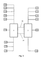
- Fig. 1 shows an overview of the cruise control device.
- the cruise control device comprises a cruise control unit 1 from a first programmable logic control system 2 and a second programmable logic control system 3. These form mutually redundant management and monitoring parts of the cruise control device.
- SPS programmable logic control systems
- Each of the two PLCs receives signals via input modules or a distributed I / O via a dedicated DP bus.
- the calculated sizes of the individual PLCs are exchanged under the PLC via a coupling between them.
- the output signals generated by the PLC are transferred into the safety circuit with effect. Conveniently, it relies on contactor contacts or relays, which are connected to the binary inputs and outputs of the other PLC.
- the PLC check the synchronization and the plausibility of the signals.
- Both the first SPS 2 and the second PLC 3 are connected to vehicle speed signalers 4 and to guideways 5, and output control signals to dedicated parts of a carrier 6. Both PLCs are thus components each a switched between the signal generator 4 and 5 and the carrier 6 partial safety circuit.
- a DP / DP coupler unit 7 is provided between the first PLC 2 and the second PLC 3. This enables a signal exchange between the first PLC and the second PLC.
- Each DP bus is designed separately for each PLC.
- the only connection between the PLC is implemented via a so-called DP / DP coupler. If a component fails within the DP bus, a PLC stop signal is generated. The output relays of the PLC drop out, whereby a safety brake of the conveyor system is applied due to the quiescent current principle.
- the arrangement thus formed forms a two-channel evaluation system.
- This evaluation system is expediently diversified.
- different hardware is used for the first PLC 2 and the second PLC 3.
- the PLC 2 can be implemented as a control system of the type S7-400 and the PLC 3 as a control system of the type S7-300 from Siemens.
- Both channels thus each form a partial safety circuit implemented via the two PLCs. This is implemented by software in each of the two PLCs. Both channels are each incorporated via separate relay contacts in a given safety circuit of the carrier.
- connection of the two PLC with the peripheral components 4, 5 and 6 is advantageously carried out via a bus transmission system.
- a Profibus-DP connection is used.
- WAGO terminals for digital and analog signals can be used as controller boards for the peripherals.
- the bus systems are hardware-identical, ie homogeneous.
- Fig. 2 shows an overview of signaling components for vehicle speed and travel.
- a signaling components for the driving speed 4 a tachogenerator 8 with a threshold value 9 is provided on the one hand.
- the tachogenerator operates independent of mains voltage.
- the threshold switch is used to signal an overspeed.
- a shaft switch assembly 10 is used. This forms a point-by-point speed monitoring device which is used to monitor the driving speed during the synchronization phase and in the deceleration areas of the conveyor system.
- the tachogenerator serves as a preferred actual value encoder for the driving speed
- the shaft switch assembly provides an additional monitoring option for the driving speed of the conveyor cage at certain points of the shaft.
- magnetic switches are preferably used with a mining license. This is coupled with a test device, which is designed switchable and interacts with the system without feedback.
- Fig. 3 shows some exemplary outputs and inputs of the PLC 2 and the PLC 3 and the signals applied to these inputs and processed by both components.
- electrical components commercially available standard parts can be used.
- the link to the central PLC is described below by way of example.
- a redundant input and output 14 exchanges signals with the tachogenerator 8 and with the Winkel suitsencoder 11 and with a drive shaft of the carrier.
- the input and output with respect to the angle-step coder can also not be designed redundantly.
- the signal from the angle step encoder of each of the two steps is read in via the input and output at the respective PLC.
- the input and output 15 is designed completely redundant. This serves as an interface for signals on the actual value of a driving lever, on the current direction of travel and on the current operating state of an automatic or manual operation.
- the input and output 16 serves to output the incoming signals from a brake system for the purpose of visualization.
- This input and output is not redundant, but only assigned to PLC 2.
- the first PLC 2 and the second PLC 3 each have an input and output 17a and 17b for hardware signals. These are on each in the PLC adapted existing hardware and are used for their programming.
- the redundant input and output 18 is provided for an output relay for blocking a departure, for an emergency stop signal, a signal of a stationary and / or slipping in the direction of the machine and / or for a Aufholsignal.
- the inputs and outputs 19 and 20 serve as interfaces for output signals for a brake setpoint in an automatic mode or for a setpoint of other converter devices.
- the data exchange between the PLC 2 and the PLC 3 takes place as described via a DP / DP coupler.
- This has devices 21 and 22 for a bus separation.
- the trained redundant control unit allows two-channel monitoring, which act in the safety circuit of the conveyor system.
- a synchronization of both control channels is detected and detected errors are detected.
- the first PLC 2 and in the second PLC 3 monitoring functions are implemented in software.
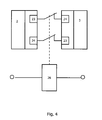
- the basic principle pursued for the synchronization monitoring is in Fig. 4 shown.
- the signals applied to the contactors and generated by one of the PLCs are evaluated by the other PLC for synchronization monitoring.
- the contactors can be connected to other contacts with the safety circuit of the carrier. When a wire breaks, the contactors are disconnected and the now inactive synchronization monitoring triggers in each of the programmable logic controllers 2 and 3 corresponding safety routines.
- the signals monitored for synchronization in both PLCs are composed of control signals from the safety circuits, system parameters calculated in both PLCs, and condition monitors executed by both PLCs.
- the following control signals are expediently monitored for synchronization: control signals from terminating relays, signals from a detection relay via a creeping machine, signals from a relay via a blocked exit, signals from directional relays and signals from system-specific control contactors.
- a synchronous monitoring of the following internal PLC generated or processed signals is executed: a calculated value for the depth, in double-staggered conveyors of each calculated for a first and a second strand depth, monitoring parameters of Winkel suitsencoders, in particular certain predetermined limits, a sum of Teufenhong double-decker conveyor systems, the signals obtained from the tachogenerator, calculated, stored or entered setpoint curves for the control system's release behavior and the values of the continuous monitoring curves for the conveyor's travel speed stored in both PLCs.
- the following monitoring parameters are expediently checked for consistency by both PLCs: a current status of a limit switch for a depth calculation, a match of depth factors, jumps in the calculated depths, a switching behavior of the cutoff switches, in particular their switching outside a window range, and a check of the calculated depths a predefined deviation at each cutoff switch. Furthermore, exceeding of limit values of double or double Conveyors of Winkel Colourencoder executed.
- the above-mentioned monitors are designed to be testable.
- the comparison parameter is a software-type simulation that simulates the effects of each variable test parameter on the condition of the other system parameters. Conveniently, this step sequences are provided so that no additional programming technology must be used. As a result, regular tests are time-efficient and exactly executable. For safety reasons, such a test can only be carried out if a safety brake device is triggered. It is executed via visualization on an external computer system and access to at least one of the two PLCs.
- Fig. 5 shows an exemplary coupling of the tachometer generators 8 and angle step encoder 10 with the drive elements of the carrier.
- the signal generator for the speed and the delivery path are duplicated.
- the signals generated by these duplicate parts are checked for consistency in the PLC.
- a strand determines the entire direction of rotation and conveying of the system. It is true that the executed on a run movement in the conveyor shaft into the conveyor on a direction of travel "hanging" corresponds. Thus, the calculations of depths refer to these definitions.
- a DC motor 27 which is fed by a Leonardumformer not shown here.
- This consists of a starter motor with a starter, in particular a liquid starter, a synchronous motor and a DC generator.
- an excitation current of the DC generator via a DC-DC converter fed. It contains a power converter, a speed controller and a current controller. For this a 4-quadrant operation is used.
- the constant excitation current generated by the synchronous motor is also fed via a DC-DC converter.
- a traction sheave 29 is driven at a substantially constant power. Both the DC motor 27 and the traction sheave ever a toothed belt device 30 is arranged, which transmits the movements of these components to each tachogenerator 8 and an angle step encoder 10 without slip.
- Fig. 6 shows an exemplary shaft switch assembly in a first strand 31 a and a second strand 31 b.
- a shaft switch magnetic switch with mining approval are suitably used. These are preferably mounted in the Ab Kunststoff- and delay range. The required number can be adapted to the actual conveyor system.
- two Abticianschalter are paired for each Trum.
- the corresponding to the respective first Abêtschalter second Ab Kunststoffschalter is mounted in the opposite of the traction sheave 29.
- three pairs Ab Kunststoffschalter 32, 33 and 34 are distributed over both runs.
- Additional switches 35 and 36 are provided in the area of a location referred to herein as "turf bank" or in the region of the filling location on the shaft bottom.
- the paired Ab Kunststoffschalter perform two functions.
- a first function consists in a Abgreskontrolle and a speed monitoring, which is related to the Teufenwert of the respective strand.
- a second function is that these Ab Kunststoffschalter form a benchmark for a Teufenlitis. The defined by this fixed point is formed by the values of the total depth reduced by the depth value of the diversion point.
- the determination of the depth in each run is carried out by the evaluation of the angle step signals from each angle step encoder in conjunction with a depth factor.
- the depth is calculated both in the first PLC 2 and in the second PLC 3 for each run.
- Each angle step encoder is directly coupled to the Profibus of the respective PLC via a controller board for the connection to the Profibus.
- the value of the angle step encoder received in each of the PLCs and the depth value determined thereby are exchanged between the two PLCs via the DP / DP coupling and compared with each other.
- a calibration run of the conveyor is performed. This is expediently at a control panel of the system by means of a key switch triggered to prevent unintentional recalibrations of the system and thus safety risks.
- a preset signal is transmitted to the angle step encoder at the stationary shutdown switch 32 of each dream. This signal is used to synchronize the absolute values of the angle step encoders with the fixed points in the shaft designated by the cutoff switches 32.
- the depth factors are recalculated each time the traction sheave is used and used to determine the depth. With such a method, wear of the traction sheave chuck can be compensated automatically. For further synchronization of the guideway with the Winkel Murphyencodern a preset value in the form of a fixed angular step is transmitted to one or both shaft switches 32 in the Winkelitzencoder.
- Y i a value for the desired speed
- x a depth value
- n an absolute depth value which indicates the depth for the start of the straight line equation
- the slope m i and the offset n i is calculated and a data block, which may be formed as part of the two PLC, stored.
- the calculations of the diversion curves are done in both PLCs. They are monitored for equality. In a design with the lowest possible cycle time within the PLC, a sufficiently long reaction time is obtained for plant control.
- the calculated speed setpoint is normalized and transferred to a drive controller in the form of a control signal.
- a drive controller in the form of a control signal.
- This is in particular the already mentioned DC chopper of Leonardumformers the prime mover.
- the control signal is also compatible with other types of drive controllers, such as direct-current DC motors, frequency converters, or other similar devices.
- the "drive on”, “drive direction” and “speed setpoint” signals are transferred to the drive controller. This signal is served by a conveyor operator Manual setpoint generator linked, whereby at any time an actual speed of the drive can be changed continuously.
- the manual setpoint generator is a combination of a setpoint potentiometer and an electronic converter. This converts variable current values into speed values. The setpoint given in this way is compared with the travel curve. If the setpoint of the manual setpoint generator is above the calculated setpoint of the travel curve, the setpoint value is taken from the calculated travel curve that is used to control the drive controller. Thus, a full display of the manual setpoint encoder also causes the carrier to automatically stop.
- the travel curve can be influenced in its Ab Kunststoffbeginninn, the deceleration and the acceleration in a visualization system, which is connected via appropriate interfaces with the two PLCs.
- a visualization system which is connected via appropriate interfaces with the two PLCs.
- PC systems on which a visualization software is implemented for example, recourse is made to PC systems on which a visualization software is implemented.
- the connection of the PC system with the PLC takes place, for example, via an MPI bus.
- the PC system is expediently designed to be redundant. If one PC fails, the visualization can be called up on the other PC.
- FIG Fig. 7 An exemplary representation of a display of the travel curve parameters is shown in FIG Fig. 7 shown.
- the figure shows an input window 40 for setting parameters for the mentioned travel curve.
- the input window contains input fields 41 for specifying a curve slope in the form of a Ab Griffinoffset, a maximum speed, a minimum speed for speed monitoring, a revision speed, an overspeed and a crawl speed.
- input fields 42 it is possible to enter a value for each of the mentioned parameters, to track an actual value and to specify a setpoint value.
- Input fields 43 allow depths, target and overspeeds for one run pretend.
- a button 44 allows a calculation of the driving curves, a diagram 45 shows the course of the parameter graphically.
- the continuous monitoring curve is calculated by scaling up with a safety factor.
- the speed provided by the tachogenerators is compared dynamically with this monitoring curve.
- a safety brake is triggered as soon as the tacho value exceeds the calculated limit value.
- the calculated diversion curve is monitored for a run down.
- a dynamic comparison of the value of the pay-off cam with the actual speed ensures that the speed follows the calculated target value. This monitoring is required especially in automatic operation. It can be provided in manual mode.
- two parameters are set for continuous speed monitoring. On the one hand, this is a percentage overspeed on the basis of a maximum speed of the carrier. On the other hand, a minimum speed is set, in which an overspeed is displayed.
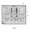
- Fig. 8 shows an exemplary representation of a display for the definition of sole areas, Teufen Attachern and Teufenlomi.
- the sole areas can be defined with an input window 46 and tracked in their setpoint and actual values. In particular, it is possible to specify this information by means of input fields 47 to 50 for each strand individually, for filling locations and different sole areas.
- a determination of limit switches for depth indicator is possible with input fields 51.
- Parameters for the depth calculation, in particular multiplication factors and offset values and encoder positions for both dreams, can be defined and tracked with input fields 52.
- Fig. 9 shows a visualization of the conveyor system, with the positions of the conveyor baskets and the conveying speeds can be detected in a simple manner.
- the visualization shows a schematic representation 53 of the first and second run with an indicated tower structure.
- the positions of the respective cars are represented by indicators 54a and 54b.
- Trumdarwolf 53 On a scale on Trumdar ein 53, the positions of the cars, especially their Teufe be read.
- Trumdar ein 53 In addition to the Trumdar ein 53 are section representations 55 and 56, in which the positions of the cars is displayed for each strand with a higher resolution. In conjunction with this, the current positions of the conveyor baskets are indicated by numbers in display boxes 57 and 58 for each run. Furthermore, an indication of the actual and the target speed.
- shown visualization can contain more, not shown here display fields. For example, indications of malfunctions, self-drives, telemetric status data at selected locations of the drive and the like further information can be displayed.
- FIG. 5 shows an exemplary speed controller protocol 59.
- the abscissa 60 of the diagram contains time information, showing the time lapses of the maximum speed monitoring curve 61, a target speed curve 62 underneath, and a measured actual speed 63 slightly fluctuating around the desired speed curve ,
- a curve 64 shows the time dependence of the measured depth value.
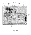
- Fig. 11 shows a visualization of the brake apparatus, in which the states of the components arranged in the brake circuit components are displayed schematically.
- the visualization shows a schematic representation 65 of the traction sheave with a brake shoe symbol 66 and a visualization of the brake mechanism 67.
- the state of the main brake mechanism is indicated in a symbolic representation 68 and the state of a mass brake serving as a safety system is displayed in a further illustration 69.
- the visualization includes a representation 70 of the brake lines and valves of the main brake device and a representation 71 of the valves for triggering the mass brake.
- a compressor system for generating the brake pressure is visualized in a representation 72.
- the states of the brake system shown in the visualization serve signals that are transmitted from the participating components via the Profibus couplings to the first and second PLC and transmitted from there to the computer system for further processing.
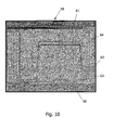
- Fig. 12 shows a visualization 73 of the already described components of the carrier.
- the visualization includes a representation 74 of the Leonard set and a representation 75 of the drive components.
- the visualization of Leonardsatzes contains in particular a representation 76 of a thermostat with a display of the current temperature, a representation 77 of the synchronous motor with display fields for temperature and operating condition, a representation 78 of the DC generator with a temperature display and a display 79 of a Throw-off engine.
- the visualization of the Leonard set contains, among other things, a visualization 80 of a lubrication circuit of the Leonard set with a representation of an oil pump arrangement, an oil tank with an attached thermostatic device and an indication of the oil pressure at various bearings within the Leonardumformers.
- the operating status of the named components is visualized by display fields and signal points.
- visualizations 81 and 82 of an air filter unit and a starter connected to the Leonard set are provided. The latter contains, among other things, signal indicators about its extension status and its operating temperature.
- the representation 75 includes a visualization 83 of the conveyor motor, a visualization 84 of the transmission and a visualization 85 of the traction sheave. Display panels for reading a current operating temperature are arranged on some of these visualizations. Furthermore, each one visualization 86 is provided for displaying the tachogenerators and Winkel suitsencoder.
- the temperature indicator for the conveyor motor shows the effectiveness of an air filter unit represented by means of a visualization 87.
- a visualization 88 is provided. This includes in particular visualized repair switches for drives, compressors and starters, switches for extending and retracting the starter or switches for starting or stopping oil pumps for the lubricating oil circuit or the fan in the area of the Leonard converter and / or the conveyor motor.
Abstract
Description
Die Erfindung betrifft eine Vorrichtung zur Fahrtregelung für eine ein- oder doppeltrümige Förderanlage nach dem Oberbegriff des Anspruchs 1. Die Erfindung betrifft weiterhin ein Verfahren zum Ausführen einer Fahrtregelung für eine derartige Förderanlage nach dem Oberbegriff des Anspruchs 10.The invention relates to a device for controlling the travel of a single or double feed conveyor according to the preamble of
Derartige Förderanlagen werden vor allem im Bergwerksanlagen betrieben. Sie dienen zum Befördern von Lasten und/oder Personen in vertikal verlaufenden Schachtanlagen. Diese Anlagen weisen eine Fahrgeschwindigkeit von bis zu 10 m/s auf. Sie sind in der Regel als Treibscheibenanlagen oder Doppeltrommelanlagen mit oder ohne Versteckeinrichtung ausgeführt.Such conveyor systems are mainly operated in mining facilities. They are used to carry loads and / or people in vertical wells. These systems have a travel speed of up to 10 m / s. They are usually designed as traction sheave or double drum systems with or without hiding.
Für derartige Förderanlagen sind für gewöhnlich mehrere Betriebsweisen vorgesehen. Eine erste Betriebsweise ist insbesondere durch eine Güterförderung, eine zweite Betriebsweise durch eine Förderung von Personen gegeben. Diese unterscheiden sich insbesondere durch ein unterschiedliches Fahrverhalten der Förderanlage, beispielsweise unterschiedliche Beschleunigungs- oder Verzögerungswerte in den Endabschnitten der Schachtanlage oder unterschiedliche Fahrgeschwindigkeiten im Schacht selbst. Es hat sich beim Betrieb derartiger Förderanlagen gezeigt, dass eine automatische Fahrsteuerung, die insbesondere bei einer Güterförderung angewendet wird, bei anderen Betriebsweisen der Anlage nachteilig ist.For such conveyors usually several modes are provided. A first mode of operation is given in particular by a freight promotion, a second mode of operation by a promotion of persons. These differ in particular by different driving behavior of the conveyor system, for example, different acceleration or deceleration values in the end sections of the shaft or different speeds in the shaft itself. It has been shown in the operation of such conveyor systems that an automatic driving control, which is particularly used in a freight promotion , is disadvantageous in other modes of operation of the plant.
Es besteht somit die Aufgabe, eine Vorrichtung zur Fahrtregelung für eine Förderanlage anzugeben, die auch von Hand betrieben werden kann, aber andererseits die erforderliche Betriebssicherheit bietet.It is therefore the object to provide a device for driving control for a conveyor system, which also operated by hand but on the other hand provides the required operational safety.
Die Aufgabe wird in ihrem Vorrichtungsaspekt mit einer Vorrichtung zur Fahrtregelung für eine ein- oder doppeltrümige Förderanlage mit den Merkmalen des Anspruchs 1 gelöst. In ihrem Verfahrensaspekt erfolgt die Lösung der Aufgabe mit einem Verfahren zur Fahrtregelung einer ein- oder doppeltrümigen Förderanlage mit den Merkmalen des Anspruchs 10.The object is achieved in its device aspect with a device for driving control for a single or double-struck conveyor system with the features of
Die Vorrichtung enthält eine Fahrtregelungseinheit aus mindestens einem ersten speicherprogrammierbaren Steuerungssystem zum Ausbilden eines Führungs- und Überwachungsteils zum Ausführen einer Steuerung für eine Fördermaschine und einem zweiten speicherprogrammierbaren Steuerungssystem zum Ausbilden eines redundanten zweiten Führungs- und Überwachungsteils. In Verbindung damit sind an einer Antriebsseite eines Seilträgers und/oder an dem Seilträger Signalgeber für eine Fahrgeschwindigkeit und Signalgeber für einen Fahrweg vorgesehen.The apparatus includes a cruise control unit comprising at least a first programmable logic control system for forming a guidance and monitoring part for executing control for a carrier and a second programmable logic controller for forming a redundant second guidance and monitoring part. In connection therewith, signal generators for a driving speed and signal transmitters for a travel path are provided on a drive side of a cable carrier and / or on the cable carrier.
Der erfindungsgemäße Grundgedanke besteht darin, ein speicherprogrammierbares Steuerungssystem zur Fahrtregelung einzusetzen. Ein solches System weist den Vorteil auf, dass die Art und Weise der Fahrtregelung auf einfache Art mittels einer Programmierung vorbestimmbar ist. Damit lassen sich insbesondere Fahrparameter vorgeben, die auch bei einem Handbetrieb sichern, dass für die Fahrsicherheit gefährliche Parameter nicht überschritten werden. Das speicherprogrammierbare Steuerungssystem ist redundant angelegt. Hierzu ist ein zweites speicherprogrammierbares Steuerungssystem vorgesehen. Damit wird gewährleistet, dass die von beiden Steuerungssystemen erfassten Betriebsparameter gleichermaßen richtig verarbeitet werden.The inventive idea is to use a programmable logic control system for cruise control. Such a system has the advantage that the manner of the cruise control in a simple manner by means of programming can be predetermined. In particular, it is possible to specify driving parameters which, even in the case of manual operation, ensure that dangerous parameters for driving safety are not exceeded. The programmable logic controller is redundant. For this purpose, a second programmable logic control system is provided. This ensures that the operating parameters captured by both control systems are equally processed correctly.
Zweckmäßigerweise weisen das erste speicherprogrammierbare Steuerungssystem und das zweite speicherprogrammierbare Steuerungssystem voneinander verschieden ausgebildete Prozessoreinheiten und Betriebssysteme auf. Dadurch wird sichergestellt, dass technische Defekte oder unentdeckte Programmierfehler mit hoher Wahrscheinlichkeit nur in einem der beiden Steuerungssysteme, aber nicht in beiden in gleicher Weise auftreten.Expediently, the first programmable logic controller system and the second programmable logic controller Control system from each other differently formed processor units and operating systems. This ensures that technical defects or undetected programming errors are likely to occur only in one of the two control systems but not in both in the same way.
Das erste und das zweite speicherprogrammierbare Steuerungssystem sind über eine DP/DP-Kopplereinheit miteinander verbunden. Die DP/DP-Kopplereinheit realisiert dabei einen zwischen den Steuerungssystemen vorhandenen Feldbus. Eine derartige Verbindung greift auf ein bewährtes und sicheres Übertragungsprotokoll zurück.The first and second programmable logic controller systems are interconnected via a DP / DP coupler unit. The DP / DP coupler unit realizes an existing between the control systems fieldbus. Such a connection relies on a proven and secure transmission protocol.
Als Signalgeber für eine Fahrgeschwindigkeit ist ein netzspannungsunabhängiger Tachogenerator vorgesehen. Dieser ist mit einem Schwellwertschalter zum Erfassen einer Übergeschwindigkeit ausgestattet. Der Tachogenerator liefert ein der vorliegenden Geschwindigkeit entsprechendes Spannungssignal. Diese Messwerterfassung benötigt keine externe Spannungsversorgung. Der Schwellwertschalter gibt beim Erreichen eines über einer gegebenen Grenze liegenden Geschwindigkeitswertes ein gesondertes Messsignal aus.As a signal generator for a driving speed a mains voltage independent tachogenerator is provided. This is equipped with a threshold for detecting an overspeed. The tachogenerator provides a voltage signal corresponding to the current speed. This data acquisition does not require an external power supply. The threshold value switch outputs a separate measurement signal when a speed value lying above a given limit is reached.
Zweckmäßigerweise ist eine rückwirkungsfrei zuschaltbare Prüfeinrichtung für eine punktweise Geschwindigkeitsüberwachung mit einer in einem Absteuer-und/oder Verzögerungsbereich montierten Schachtschalteranordnung vorgesehen. Damit kann am Fahrweg selbst die Fördergeschwindigkeit ermittelt und überwacht werden.It is expediently provided for a point-by-point speed monitoring system having a check device which can be activated without reaction and with a shaft switch arrangement mounted in a tripping and / or deceleration area. Thus, the conveying speed can be determined and monitored on the track itself.
Als Signalgeber für den Fahrweg ist bei einer zweckmäßigen Ausführungsform ein Winkelschrittencoder vorgesehen, mit dem sich der Fahrweg präzise erfassen lässt.As a signal generator for the infrastructure an angle step encoder is provided in an expedient embodiment, with which the track can be precisely detected.
Zur Signalübertragung von dem Tachogenerator und dem Winkelschrittencoder an das erste und/oder zweite speicherprogrammierbare Steuerungssystem ist zweckmäßigerweise eine Profibus-DP-Verbindung vorgesehen.For signal transmission from the tachogenerator and the Winkelschrittencoder to the first and / or second Programmable logic control system is expediently provided a Profibus-DP connection.
Das erste und das zweite speicherprogrammierbare Steuerungssystem weisen je einen Ausgang und einen Eingang für einen Signalaustausch für eine gegenseitige Gleichlaufüberwachung auf. Damit können voneinander abweichende Steuerungsabläufe innerhalb der Steuerungssysteme erkannt und daraus resultierende Gefährdungen bereits im Ansatz vermieden werden.The first and the second programmable logic control system each have an output and an input for a signal exchange for a mutual synchronization monitoring. In this way diverging control processes within the control systems can be detected and any resulting hazards can be avoided in the beginning.
Diese Ein- und Ausgänge sind bei einer zweckmäßigen Ausführungsform auf nach dem Ruhestromprinzip angesteuerte Schütze gelegt.These inputs and outputs are placed in an expedient embodiment, according to the closed-circuit principle driven contactors.
Ein Verfahren zum Ausführen einer Fahrtregelung für eine ein-oder doppeltrümige Förderanlage zeichnet sich durch ein Verwenden eines zweikanaligen diversitären Auswertesystems mit hardwareverschiedenen speicherprogrammierbaren Steuerungssystemen zum Betreiben jeweils eines Teilsicherheitskreises aus. Dabei wird jeder Teilsicherheitskreis über getrennte Schützkontakte in einen Sicherheitskreis der Förderanlage eingebunden. Beide Kanäle des Auswertesystems führen in Verbindung damit über eine DP/DP-Kopplung einen Signalaustausch aus.A method of executing cruise control for a single or double feed mill is characterized by using a dual channel, multi-purpose evaluation system with hardware distinct programmable logic control systems to operate one partial safety circuit each. Each partial safety circuit is integrated into a safety circuit of the conveyor system via separate contactor contacts. Both channels of the evaluation system exchange signals via a DP / DP link.
Bei der Ausführung des Verfahrens erfolgt für eine Überwachung einer Fahrgeschwindigkeit innerhalb eines Schachtes eine punktweise Geschwindigkeitsüberwachung und/oder ein Erzeugen geschwindigkeitsabhängiger Spannungssignale mittels Tachogeneratoren. Dabei wird für jedes speicherprogrammierbare Steuerungssystem eine teufenabhängige Geschwindigkeit für jeden Kanal des Auswertesystems errechnet und verglichen.In the execution of the method, a point-by-point speed monitoring and / or a generation of speed-dependent voltage signals by means of tachogenerators takes place for monitoring a travel speed within a shaft. In this case, a pigeon-dependent speed for each channel of the evaluation system is calculated and compared for each programmable logic control system.
Bei einer vorteilhaften Ausführungsform werden bei der Ausführung des Verfahrens durch jedes speicherprogrammierbare Steuersystem Soll-Geschwindigkeitswerte errechnet. Diese werden an einen Leistungsteil einer Antriebsvorrichtung ausgegeben.In an advantageous embodiment, setpoint speed values are calculated by each programmable logic control system during execution of the method. These are output to a power part of a drive device.
Zweckmäßigerweise erfolgt das Errechnen der Soll-Geschwindigkeitswerte dadurch, indem teufenabhängige Absteuerkurven und/oder Sollwerte für eine Geschwindigkeit des Antriebs und/oder eine Überwachungskurve für eine kontinuierliche Geschwindigkeitsüberwachung erzeugt werden. Dies wird dadurch ausgeführt, indem eine Menge teufenabhängiger Sollgeschwindigkeitsteilgeraden mit je einem Offsetparameter und je einem Steigungsparameter erzeugt werden. Dabei werden der je eine Steigungsparemeter und der je eine Offsetparameter für jede Sollgeschwindigkeitsteilgerade redundant in jedem speicherprogrammierbaren Steuersystem errechnet und auf Gleichheit überwacht. Die mit den Sollgeschwindigkeitsteilgeraden errechneten Geschwindigkeitssollwerte werden normiert und an einen Antriebsregler als dem Leistungsteil der Antriebsvorrichtung übergeben.Expediently, the calculation of the setpoint speed values is effected by generating pave-dependent skid curves and / or setpoint values for a speed of the drive and / or a monitoring curve for continuous speed monitoring. This is carried out by generating a set of rate-dependent setpoint speed substraights each having one offset parameter and one slope parameter each. In this case, the one pitch parameter and the one offset parameter for each target speed substraight are calculated redundantly in each programmable logic control system and monitored for equality. The speed setpoints calculated with the nominal speed substraction are normalized and transferred to a drive controller as the power unit of the drive device.
Die Überwachungskurve wird bei einer zweckmäßigen Ausführungsform aus der Absteuerkurve durch eine Skalierung errechnet. Dabei wird eine gemessene Ist-Geschwindigkeit dynamisch mit den Werten der Überwachungskurve verglichen. Bei einem Überschreiten der Ist-Geschwindigkeit wird schließlich eine Sicherheitsbremse ausgelöst. Die Absteuerkurve beschreibt somit einen absoluten Grenzbereich für die Überwachung der Ist-Geschwindigkeit der Förderanlage. Die Überwachungskurve führt eine zusätzliche Sicherheitstoleranz ein. Diese wird dazu benötigt, um einen zusätzlichen Spielraum für das Ansprechen der Sicherheitsbremse zu gewinnen und gleichzeitig zu sichern, dass der durch die Absteuerkurve definierte Grenzbereich der Steuerung in keinem Fall überschritten wird.The monitoring curve is calculated in an expedient embodiment of the Absteuerkurve by scaling. In this case, a measured actual speed is compared dynamically with the values of the monitoring curve. If the actual speed is exceeded, finally a safety brake is triggered. The Absteuerkurve thus describes an absolute limit for the monitoring of the actual speed of the conveyor system. The monitoring curve introduces an additional safety tolerance. This is required in order to gain additional scope for the response of the safety brake and at the same time to ensure that the limit range of the control defined by the diversion curve is never exceeded.
Die Vorrichtung zur Fahrtregelung und das Verfahren zum Ausführen der Fahrtregelung sollen nachfolgend anhand von Ausführungsbeispielen näher erläutert werden. Zur Verdeutlichung dienen die
Es zeigt:
-
Fig. 1 eine Übersichtsdarstellung grundlegender Komponenten der Fahrtregelungsvorrichtung, -
Fig. 2 eine Übersichtsdarstellung signalgebender Komponenten für Fahrgeschwindigkeit und Fahrweg, -
Fig. 3 einige beispielhafte Aus- und Eingänge der speicherprogrammierbaren Steuerungssysteme, -
Fig. 4 eine Darstellung des Grundprinzips der Gleichlaufüberwachung zwischen den speicherprogrammierbaren Steuerungssystemen, -
Fig. 5 eine beispielhafte Kopplung der Tachogeneratoren und Winkelschrittencoder mit den Antriebselementen der Fördermaschine, -
Fig. 6 eine beispielhafte Schachtschalteranordnung in einer doppeltrümigen Förderanlage, -
Fig. 7 eine beispielhafte Darstellung einer Anzeige von Fahrkurvenparametern, -
Fig. 8 eine beispielhafte Darstellung einer Anzeige zur Definition von Sohlenbereichen, Teufenzeigern und zur Teufenrechnung, -
Fig. 9 eine Visualisierung der Förderanlage, -
Fig. 10 ein beispielhaftes Fahrregler-Protokoll, -
Fig. 11 eine Visualisierung des Bremsapparates, -
Fig. 12 eine Visualisierung der Antriebskomponenten der Fördermaschine.
-
Fig. 1 an overview of basic components of the cruise control device, -
Fig. 2 an overview of signal-generating components for driving speed and route, -
Fig. 3 some exemplary outputs and inputs of the programmable logic controller systems, -
Fig. 4 a representation of the basic principle of synchronization monitoring between the programmable logic control systems, -
Fig. 5 an exemplary coupling of the tachogenerators and angle step encoder with the drive elements of the carrier, -
Fig. 6 an exemplary shaft switch assembly in a double-struck conveyor system, -
Fig. 7 an exemplary representation of a display of driving curve parameters, -
Fig. 8 an exemplary representation of a display for the definition of sole areas, Teufenzeigern and Teufenrechnung, -
Fig. 9 a visualization of the conveyor system, -
Fig. 10 an exemplary speed controller protocol, -
Fig. 11 a visualization of the brake system, -
Fig. 12 a visualization of the drive components of the carrier.
Bei der nachfolgenden Beschreibung wird von einer Fördermaschine ausgegangen, die als doppeltrümige Treibscheibenanlage mit einem ersten Trum und einem zweiten Trum ausgebildet ist. Jedes Trum weist einen Förderkorb auf, der in mehrere Etagen unterteilt sein kann. Einer der beiden Förderkörbe ist an einem oberschlägigen Seil angeschlagen.In the following description, it is assumed that a carrier, which is designed as a double-pulley traction sheave with a first strand and a second strand. Each course has a conveyor basket, which can be divided into several floors. One of the two conveyor baskets is struck on an oversize rope.
Jeder der beiden SPS werden Signale über Eingangsbaugruppen oder eine dezentrale Peripherie über einen dafür vorgesehenen DP-Bus zugeführt. Die berechneten Größen der einzelnen SPS werden über eine zwischen diesen ausgebildete Kopplung unter den SPS ausgetauscht. Die von den SPS gebildeten Ausgangssignale werden mit Wirkung in den Sicherheitskreis übertragen. Zweckmäßigerweise wird dabei auf Schützkontakte oder Relais zurückgegriffen, die an die binären Ein- und Ausgänge der jeweils anderen SPS geschaltet sind. Die SPS prüfen den Gleichlauf und die Plausibilität der Signale.Each of the two PLCs receives signals via input modules or a distributed I / O via a dedicated DP bus. The calculated sizes of the individual PLCs are exchanged under the PLC via a coupling between them. The output signals generated by the PLC are transferred into the safety circuit with effect. Conveniently, it relies on contactor contacts or relays, which are connected to the binary inputs and outputs of the other PLC. The PLC check the synchronization and the plausibility of the signals.
Sowohl die erste SPS 2 als auch die zweite SPS 3 sind mit Signalgebern für eine Fahrgeschwindigkeit 4 und mit Signalgebern für einen Fahrweg 5 verbunden und geben Steuerungssignale an dafür vorgesehene Teile einer Fördermaschine 6 aus. Beide SPS sind damit Bestandteile je eines zwischen die Signalgeber 4 und 5 und die Fördermaschine 6 geschalteten Teilsicherheitskreises.Both the
Zwischen der ersten SPS 2 und der zweiten SPS 3 ist eine DP/DP-Kopplereinheit 7 vorgesehen. Diese ermöglicht einen zwischen der ersten SPS und der zweiten SPS ablaufenden Signalaustausch.Between the
Jeder DP-Bus ist für jede SPS separat aufgebaut. Die einzige Verbindung zwischen den SPS wird über einen so genannten DP/DP-Koppler realisiert. Bei Ausfall einer Komponente innerhalb des DP-Busses wird ein SPS-Stoppsignal erzeugt. Dabei fallen die Ausgangsrelais der SPS ab, wobei aufgrund des Ruhestromprinzips eine Sicherheitsbremse der Förderanlage aufgelegt wird.Each DP bus is designed separately for each PLC. The only connection between the PLC is implemented via a so-called DP / DP coupler. If a component fails within the DP bus, a PLC stop signal is generated. The output relays of the PLC drop out, whereby a safety brake of the conveyor system is applied due to the quiescent current principle.
Die so gebildete Anordnung bildet ein zweikanaliges Auswertesystem. Dieses Auswertesystem ist zweckmäßigerweise diversitär ausgebildet. Das bedeutet, dass für die erste SPS 2 und die zweite SPS 3 jeweils auf verschiedene Hardware zurückgegriffen wird. So kann beispielsweise die SPS 2 als ein Steuerungssystem des Typs S7-400 und die SPS 3 als ein Steuerungssystem des Typs S7-300 der Firma Siemens realisiert sein. Beide Kanäle bilden damit jeweils einen über die beiden SPS realisierten Teilsicherheitskreis aus. Dieser ist jeweils in jeder der beiden SPS softwaremäßig implementiert. Beide Kanäle werden jeweils über getrennte Relaiskontakte in einen gegebenen Sicherheitskreis der Fördermaschine eingebunden.The arrangement thus formed forms a two-channel evaluation system. This evaluation system is expediently diversified. This means that different hardware is used for the
Die Verbindung der beiden SPS mit den peripheren Komponenten 4, 5 und 6 erfolgt zweckmäßigerweise über ein Busübertragungssystem. Hierzu wird insbesondere auf eine Profibus-DP-Verbindung zurückgegriffen. Als Anschaltbaugruppen für die Peripherie können beispielsweise WAGO-Klemmen für digitale und analoge Signale eingesetzt werden. Im Unterschied zu den hardwareverschiedenen SPS sind die Bussysteme hardwaregleich, d.h. homogen, ausgebildet.The connection of the two PLC with the
Zusätzlich dazu kommt eine Schachtschalteranordnung 10 zum Einsatz. Diese bildet eine punktweise Geschwindigkeitsüberwachungseinrichtung, die zur Überwachung der Fahrgeschwindigkeit während der Gleichlaufphase und in den Verzögerungsbereichen der Förderanlage. Der Tachogenerator dient als bevorzugter Istwert-Geber für die Fahrgeschwindigkeit, die Schachtschalteranordnung bietet eine zusätzliche Überwachungsmöglichkeit für die Fahrgeschwindigkeit des Förderkorbes an bestimmten Punkten des Schachtes. Als Schachtschalter werden vorzugsweise Magnetschalter mit einer Bergbauzulassung eingesetzt. Diese ist mit einer Prüfeinrichtung gekoppelt, die zuschaltbar ausgeführt ist und rückwirkungsfrei mit dem System zusammenwirkt.In addition, a
Die meisten Ein- und Ausgänge sind sowohl an der SPS 2 als auch an der SPS 3 vorgesehen und somit redundant angelegt. An einem ersten redundanten Ein- und Ausgang 12 werden Signale aus und zu einer Signalanlage und Sperreinrichtung empfangen und/oder ausgegeben. Des weiteren werden über den Ein- und Ausgang 12 Signale mit einer DP-Peripherie getauscht, die zur Signalgewinnung dient. Dies betrifft insbesondere Ein- und Ausgaben von "Fertig"-Signalen, Signalen über eine gesperrte Abfahrt oder Notsignale. In Verbindung damit werden über den Ein- und Ausgang 12 auch Signale übertragen, die nicht notwendigerweise redundant an beiden SPS-Einheiten anliegen müssen. Dies betrifft insbesondere Signale, die für ein Taglogging einer Visualisierung verwendet werden.Most inputs and outputs are provided on both the
An einem redundant an der SPS 2 und der SPS 3 vorhandenen Ein- und Ausgang 13 werden zusätzliche Signale in einem Schaltschrank des Fahrtreglers, Signale von Absteuerschaltern und (bei einer doppeltrümigen Förderanlage) Signale von redundanten Torgebern in Verbindung mit einer Antivalenzprüfung ausgetauscht. Der Ein- und Ausgang 13 ist ebenfalls für Steuersignale für Sicherheitseinrichtungen an Schachttoren, insbesondere für Lichtschranken, vorgesehen.On a redundant on the
Ein redundanter Ein- und Ausgang 14 tauscht Signale mit dem Tachogenerator 8 sowie mit dem Winkelschrittencoder 11 sowie mit einer Treibwelle der Fördermaschine aus. Bei einer doppeltrümigen Anlage kann der Ein- und Ausgang bezüglich des Winkelschrittencoders auch nicht redundant angelegt sein. In einem solchen Fall wird über den Ein- und Ausgang an der jeweiligen SPS das Signal des Winkelschrittencoders von jedem der beiden Trume eingelesen.A redundant input and
Der Ein- und Ausgang 15 ist vollständig redundant ausgeführt. Dieser dient als Schnittstelle für Signale über den Istwert eines Fahrhebels, über die aktuelle Fahrtrichtung und über den momentanen Betriebszustand eines Automatik- oder Handbetriebs.The input and
Der Ein- und Ausgang 16 dient einer Ausgabe der von einer Bremsanlage einlaufenden Signale zum Zweck einer Visualisierung. Dieser Ein- und Ausgang ist nicht redundant angelegt, sondern nur der SPS 2 zugeordnet. Die erste SPS 2 und die zweite SPS 3 weisen je einen Ein- und Ausgang 17a und 17b für Hardwaresignale auf. Diese sind auf die jeweils in den SPS vorhandene Hardware angepasst und dienen zu deren Programmierung.The input and
Der redundant angelegte Ein- und Ausgang 18 ist für ein Ausgangsrelais zum Sperren einer Abfahrt, für ein Not-Aus-Signal, ein Signal einer stehenden und/oder in Richtung Hängen schleichenden Maschine und/oder für ein Aufholsignal vorgesehen.The redundant input and
Die Ein- und Ausgänge 19 und 20 dienen als Schnittstellen für Ausgangssignale für einen Bremssollwert bei einem Automatikbetrieb bzw. für einen Sollwert weiterer Umformereinrichtungen.The inputs and outputs 19 and 20 serve as interfaces for output signals for a brake setpoint in an automatic mode or for a setpoint of other converter devices.
Der Datenaustausch zwischen der SPS 2 und der SPS 3 erfolgt wie beschrieben über einen DP/DP-Koppler. Dieser weist Vorrichtungen 21 und 22 für eine Bustrennung auf.The data exchange between the
Die so ausgebildete redundant angelegt Steuereinheit erlaubt zweikanalige Überwachungen, die in den Sicherheitskreis der Förderanlage wirken. Dabei wird insbesondere ein Gleichlauf beider Steuerkanäle erfasst und dabei auftretende Fehler erkannt. Hierzu sind in der ersten SPS 2 und in der zweiten SPS 3 Überwachungsfunktionen softwareartig implementiert.The trained redundant control unit allows two-channel monitoring, which act in the safety circuit of the conveyor system. In particular, a synchronization of both control channels is detected and detected errors are detected. For this purpose in the
Das für die Gleichlaufüberwachung verfolgte Grundprinzip ist in
Die in beiden SPS auf Gleichlauf überwachten Signale setzen sich zusammen aus Steuersignalen aus den Sicherheitskreisläufen, in beiden SPS errechneten Systemparametern und durch beiden SPS ausgeführte Zustandsüberwachungen. Zweckmäßigerweise werden folgende Steuersignale auf Gleichlauf überwacht: Steuersignale aus Abschlussrelais, Signale aus einem Nachweisrelais über eine schleichende Maschine, Signale aus einem Relais über eine gesperrte Abfahrt, Signale aus Fahrtrichtungsrelais und Signale aus anlagenspezifischen Steuerschützen.The signals monitored for synchronization in both PLCs are composed of control signals from the safety circuits, system parameters calculated in both PLCs, and condition monitors executed by both PLCs. The following control signals are expediently monitored for synchronization: control signals from terminating relays, signals from a detection relay via a creeping machine, signals from a relay via a blocked exit, signals from directional relays and signals from system-specific control contactors.
Zweckmäßigerweise wird eine Gleichlaufüberwachung folgender SPS-intern erzeugter oder verarbeiteter Signale ausgeführt: ein errechneter Wert für die Teufe, bei doppeltrümigen Förderanlagen der jeweils für einen ersten und einen zweiten Trum errechnete Teufenwert, Überwachungsparameter des Winkelschrittencoders, insbesondere gewisse vorgegebene Grenzwerte, eine Summe der Teufenwerte bei doppeltrümigen Förderanlagen, die aus dem Tachogenerator gewonnen Signale, errechnete, gespeicherte oder eingegebene Sollwertkurven für das Absteuerverhalten der Förderanlage und die Werte der in beiden SPS gespeicherten kontinuierlichen Überwachungskurven für die Fahrgeschwindigkeit der Förderanlage.Conveniently, a synchronous monitoring of the following internal PLC generated or processed signals is executed: a calculated value for the depth, in double-staggered conveyors of each calculated for a first and a second strand depth, monitoring parameters of Winkelschrittencoders, in particular certain predetermined limits, a sum of Teufenwerte double-decker conveyor systems, the signals obtained from the tachogenerator, calculated, stored or entered setpoint curves for the control system's release behavior and the values of the continuous monitoring curves for the conveyor's travel speed stored in both PLCs.
Durch beide SPS werden zweckmäßigerweise folgende Überwachungsparamater auf Konsistenz überprüft: ein momentaner Status eines Endschalters bei einer Teufenrechnung, eine Übereinstimmung von Teufenfaktoren, Sprünge in den errechneten Teufen, ein Schaltverhalten der Absteuerschalter, insbesondere deren Schalten außerhalb eines Fensterbereiches, und eine Kontrolle der berechneten Teufe auf eine vordefinierte Abweichung an jedem Absteuerschalter. Weiterhin werden ein Überschreiten von Grenzwerten des oder bei doppeltrümigen Förderanlagen der Winkelschrittencoder ausgeführt. Die erwähnten Überwachungen sind prüfbar ausgeführt. Als Vergleichsgröße dient eine softwareartige Simulation, die die Auswirkungen jedes veränderlichen Prüfparameters auf den Zustand der weiteren Anlagenparameter simuliert. Zweckmäßigerweise sind hierbei Schrittketten vorgesehen, so dass keine zusätzliche Programmiertechnik eingesetzt werden muss. Dadurch sind turnusmäßige Prüfungen zeitlich effizient und exakt ausführbar. Aus Sicherheitsgründen ist eine derartige Prüfung nur dann ausführbar, wenn eine Sicherheitsbremseinrichtung ausgelöst ist. Sie wird über eine Visualisierung an einem externen Computersystem und einen Zugriff auf mindestens eine der beiden SPS ausgeführt.The following monitoring parameters are expediently checked for consistency by both PLCs: a current status of a limit switch for a depth calculation, a match of depth factors, jumps in the calculated depths, a switching behavior of the cutoff switches, in particular their switching outside a window range, and a check of the calculated depths a predefined deviation at each cutoff switch. Furthermore, exceeding of limit values of double or double Conveyors of Winkelschrittencoder executed. The above-mentioned monitors are designed to be testable. The comparison parameter is a software-type simulation that simulates the effects of each variable test parameter on the condition of the other system parameters. Conveniently, this step sequences are provided so that no additional programming technology must be used. As a result, regular tests are time-efficient and exactly executable. For safety reasons, such a test can only be carried out if a safety brake device is triggered. It is executed via visualization on an external computer system and access to at least one of the two PLCs.
Als Antrieb der Fördermaschine wird bei dem in
Über ein an dem Gleichstrommotor 27 angeschlossenes Getriebe 28 wird eine Treibscheibe 29 mit einer im wesentlichen konstanten Leistung angetrieben. Sowohl an dem Gleichstrommotor 27 als auch an der Treibscheibe ist je eine Zahnriemenvorrichtung 30 angeordnet, die die Bewegungen dieser Komponenten an je einen Tachogenerator 8 und einen Winkelschrittencoder 10 schlupffrei überträgt.About a connected to the
Die paarigen Absteuerschalter führen zwei Funktionen aus. Eine erste Funktion besteht in einer Absteuerkontrolle und einer Geschwindigkeitsüberwachung, die auf den Teufenwert des jeweiligen Trums bezogen ist. Eine zweite Funktion besteht darin, dass diese Absteuerschalter einen Festpunkt für eine Teufenrechnung bilden. Der dadurch definierte Festpunkt wird durch die Werte der Gesamtteufe vermindert um den Teufenwert des Absteuerpunktes gebildet.The paired Absteuerschalter perform two functions. A first function consists in a Absteuerkontrolle and a speed monitoring, which is related to the Teufenwert of the respective strand. A second function is that these Absteuerschalter form a benchmark for a Teufenrechnung. The defined by this fixed point is formed by the values of the total depth reduced by the depth value of the diversion point.
Die Ermittlung der Teufe in jedem Trum wird durch die Auswertung der Winkelschrittsignale aus jedem Winkelschrittencoder in Verbindung mit einem Teufenfaktor ausgeführt. Die Berechnung der Teufe erfolgt sowohl im ersten SPS 2 als auch im zweiten SPS 3 für jeden Trum. Jeder Winkelschrittencoder ist über eine Anschaltbaugruppe für die Anbindung an den Profibus direkt an den Profibus der jeweiligen SPS gekoppelt. Der in jedem der SPS empfangene Wert des Winkelschrittencoders und der dabei ermittelte Teufenwert wird über die DP/DP-Kopplung zwischen beiden SPS ausgetauscht und miteinander verglichen.The determination of the depth in each run is carried out by the evaluation of the angle step signals from each angle step encoder in conjunction with a depth factor. The depth is calculated both in the
Die Berechnung der Teufe wird mit folgenden Schritten ausgeführt:
- Der Nullpunkt jedes Winkelschrittencoders wird zu Beginn so eingestellt, dass dieser mit einer zweckmäßig gewählten Sicherheitsreserve über dem Teufenwert der Treibscheibe liegt. Dadurch ist gesichert, dass die ausgegebenen Signale immer in einem positiven Bereich liegen und die Teufenberechnung immer mit positiven Zahlen ausgeführt wird. Die konventionsbedingten negativen Anzeigen für die Position eines Förderkorbes im Schacht bzw. die positiven Werte für eine Position eines Förderkorbes über der Oberfläche werden durch softwaremäßig vorgegebene Offsetwerte erzeugt und in einem Visualisierungssystem entsprechend ausgegeben. Als Nullpunkt für die Visualisierung kann beispielsweise der durch
den Schachtschalter 35 definierte Ort der Rasenbank gewählt werden, der durch einen bestimmten Punkt des Förderkorbes, beispielsweise durch dessen untere Etage, berührt wird.
- The zero point of each angle step encoder is set at the beginning in such a way that it lies above the depth value of the traction sheave with a suitably selected safety margin. This ensures that the output signals are always in a positive range and the depth calculation is always performed with positive numbers. The convention-related negative indications for the position of a conveyor cage in the shaft or the positive values for a position of a conveyor cage above the surface are generated by software-preset offset values and output accordingly in a visualization system. As a zero point for the visualization, for example, the location of the turf bank defined by the
shaft switch 35 can be selected, which is touched by a specific point of the conveyor cage, for example by its lower level.
Für eine Kalibrierung der Teufenmessung wird eine Eichfahrt der Fördereinrichtung ausgeführt. Diese wird zweckmäßigerweise an einem Steuerpult der Anlage mittels eines Schlüsselschalters ausgelöst, um unbeabsichtigte Neukalibrierungen des Systems und damit Sicherheitsrisiken zu vermeiden. Zu Beginn der Eichfahrt wird am ortsfesten Absteuerschalter 32 jedes Trumes ein Presetsignal an die Winkelschrittencoder übertragen. Durch dieses Signal werden die Absolutwerte der Winkelschrittencoder mit dem durch die Absteuerschalter 32 bezeichneten Festpunkte im Schacht synchronisiert.For calibrating the depth measurement, a calibration run of the conveyor is performed. This is expediently at a control panel of the system by means of a key switch triggered to prevent unintentional recalibrations of the system and thus safety risks. At the beginning of the calibration run, a preset signal is transmitted to the angle step encoder at the
Bei einem synchronisierten System wird der Teufenfaktor, d.h. der Proportionalitätsfaktor zwischen den am Winkelschrittencoder erfassten Winkelschritte und der Teufe, wie folgt ermittelt:
- Zunächst wird die Anzahl der Winkelschritte zwischen
dem Absteuerschalter 32 und dem im unteren Schachtbereich montierten Absteuerschalter 34 erfasst. Die Distanz zwischen den beiden ortsfest angeordneten Schaltern ist bekannt und konstant. Der Teufenfaktor ergibt sich somit aus dem Verhältnis des konstanten Abstandswertes zwischen den Schachtschaltern und der dazu gehörenden Anzahl der ermittelten Winkelschritte am Winkelschrittencoder. Dabei wird für die Berechnung desTeufenfaktors im Trum 31 b die Position desAbsteuerschalters 32im Trum 31 b und des Absteuerschalters 34im Trum 31 a verwendet. Entsprechend wird der Teufenfaktor fürden Trum 31 a bestimmt, indem die Position desAbsteuerschalters 32im Trum 31 a und die Position desAbsteuerschalters 34im Trum 31 b als Grundlage genommen werden. Die Ergebnisse Prozedur werden als ungültig verworfen, sobald ein Fehler in der Teufenrechnung oder ein Defekt an den Schachtschaltern festgestellt wird.
- First, the number of angular steps between the
Absteuerschalter 32 and mounted in the lowershaft region Absteuerschalter 34 is detected. The distance between the two fixed switches is known and constant. The depth factor thus results from the ratio of the constant distance value between the shaft switches and the associated number of determined angle steps at the angle step encoder. In this case, the position of theAbsteuerschalters 32 instrand 31 b and theAbsteuerschalters 34 instrand 31 a is used for the calculation of Teufenfaktors instrand 31 b. Accordingly, the Teufenfaktor for thestrand 31 a is determined by the position of theAbsteuerschalters 32 in thestrand 31 a and the position of theAbsteuerschalters 34 instrand 31 b are taken as a basis. The results procedure will be invalidated as soon as an error in the depth calculation or a failure at the shaft switches is detected.
Die Teufenfaktoren werden bei jedem Betrieb der Treibscheibe neu berechnet und zur Ermittlung der Teufe verwendet. Mit einem solchen Verfahren kann ein Verschleiß des Treibscheibenfutters selbsttätig ausgeglichen werden. Zur weiteren Synchronisation des Fahrweges mit den Winkelschrittencodern wird an einem oder beiden Schachtschaltern 32 ein Preset-Wert in Form eines festen Winkelschrittes in die Winkelschrittencoder übertragen.The depth factors are recalculated each time the traction sheave is used and used to determine the depth. With such a method, wear of the traction sheave chuck can be compensated automatically. For further synchronization of the guideway with the Winkelschrittencodern a preset value in the form of a fixed angular step is transmitted to one or both shaft switches 32 in the Winkelschrittencoder.
Bei einem Aufholen erfolgt am Absteuerschalter 32 und bei einem Hängen erfolgt am Absteuerschalter 34 eine weitere Teufenkorrektur. Dabei wird der am Winkelschrittencoder errechnete Wert der Teufe mit dem Wert des Festpunktes verglichen. Die dabei ermittelte Differenz wird als ein Offset auf die Teufe addiert, sodass der Antrieb zielgenau gefahren wird. Mit einem solchen Mittel kann ein Seilrutsch oder eine Seildehnung bei der Teufenberechnung ausgeglichen oder auch festgestellt werden.When catching up takes place at the
In Abhängigkeit von der Teufe werden Absteuerkurven und/oder Sollwerte für die Geschwindigkeit des Antriebs sowie eine Überwachungskurve für eine kontinuierliche Geschwindigkeitsüberwachung für die Fahrwegenden berechnet. Jede Absteuerkurve setzt sich zusammen aus einer Reihe von Teilgeraden Yi = mi (X + ni), wobei Yi ein Wert für die Sollgeschwindigkeit, x ein Teufenwert und n ein absoluter Teufenwert darstellt, der die Teufe für den Beginn der Geradengleichung angibt. Für jede der Teilgeraden Yi wird die Steigung mi und der Offset ni berechnet und ein einen Datenbaustein, der als Teil der beiden SPS ausgebildet sein kann, abgelegt. Die Berechnungen der Absteuerkurven erfolgen sämtlich in beiden SPS. Sie werden auf Gleichheit überwacht. Bei einer Gestaltung mit einer möglichst geringen Zykluszeit innerhalb der SPS wird ein hinreichend großer Reaktionszeitraum zur Anlagensteuerung gewonnen.Depending on the depth, tramlines and / or setpoint values for the speed of the drive as well as a monitoring curve for continuous speed monitoring for the end-of-travel are calculated. Each diversion curve is composed of a series of substraits Y i = m i (X + n i ), where Y i represents a value for the desired speed, x a depth value and n an absolute depth value which indicates the depth for the start of the straight line equation , For each of the partial lines Y i , the slope m i and the offset n i is calculated and a data block, which may be formed as part of the two PLC, stored. The calculations of the diversion curves are done in both PLCs. They are monitored for equality. In a design with the lowest possible cycle time within the PLC, a sufficiently long reaction time is obtained for plant control.
Der errechnete Geschwindigkeitssollwert wird normiert und in Form eines Steuersignals an einen Antriebsregler übergeben. Dies ist insbesondere der bereits erwähnte Gleichstromsteller des Leonardumformers der Antriebsmaschine. Das Steuersignal ist jedoch auch zu Antriebsreglern anderer Bauart, wie beispielsweise Gleichstromstellern für Gleichstrommotore, Frequenzumrichter oder dergleichen andere Einheiten kompatibel. Dem Antriebsregler werden die Signale "Antrieb ein", "Richtung Antrieb" und "Geschwindigkeitssollwert" übergeben. Dieses Signal wird mit einem von einem Fördermaschinisten bedienten Handsollwertgeber verknüpft, womit jederzeit eine Ist-Geschwindigkeit des Antriebs kontinuierlich verändert werden kann.The calculated speed setpoint is normalized and transferred to a drive controller in the form of a control signal. This is in particular the already mentioned DC chopper of Leonardumformers the prime mover. However, the control signal is also compatible with other types of drive controllers, such as direct-current DC motors, frequency converters, or other similar devices. The "drive on", "drive direction" and "speed setpoint" signals are transferred to the drive controller. This signal is served by a conveyor operator Manual setpoint generator linked, whereby at any time an actual speed of the drive can be changed continuously.
Der Handsollwertgeber ist eine Kombination aus einem Sollwertpotentiometer und einem elektronischen Wandler. Durch diesen werden veränderbare Stromstärkewerte in Geschwindigkeitswerte umgesetzt. Der so gegebene Sollwert wird mit der Fahrkurve verglichen. Liegt der Sollwert des Handsollwertgebers über dem errechneten Sollwert der Fahrkurve, wird der Sollwert aus der errechneten Fahrkurve, der zur Steuerung des Antriebsreglers verwendet wird, übernommen. Somit führt auch eine Vollauslage des Handsollwertgebers dazu, dass die Fördermaschine selbsttätig absteuert.The manual setpoint generator is a combination of a setpoint potentiometer and an electronic converter. This converts variable current values into speed values. The setpoint given in this way is compared with the travel curve. If the setpoint of the manual setpoint generator is above the calculated setpoint of the travel curve, the setpoint value is taken from the calculated travel curve that is used to control the drive controller. Thus, a full display of the manual setpoint encoder also causes the carrier to automatically stop.
Die Fahrkurve kann in ihrem Absteuerbeginn, der Verzögerung und der Beschleunigung in einem Visualisierungssystem, das über entsprechende Schnittstellen mit den beiden SPS verbunden ist, beeinflusst werden. Hierzu wird beispielsweise auf PC-Systeme zurückgegriffen, auf denen eine Visualisierungssoftware implementiert ist. Die Verbindung des PC-Systems mit den SPS erfolgt beispielsweise über einen MPI-Bus. Das PC-System ist zweckmäßigerweise redundant ausgelegt. Bei Ausfall eines PC kann die Visualisierung an dem anderen PC aufgerufen werden.The travel curve can be influenced in its Absteuerbeginninn, the deceleration and the acceleration in a visualization system, which is connected via appropriate interfaces with the two PLCs. For this purpose, for example, recourse is made to PC systems on which a visualization software is implemented. The connection of the PC system with the PLC takes place, for example, via an MPI bus. The PC system is expediently designed to be redundant. If one PC fails, the visualization can be called up on the other PC.
Eine beispielhafte Darstellung einer Anzeige der Fahrkurvenparameter ist in
Aufbauend auf die errechnete Absteuerkurve wird die kontinuierliche Überwachungskurve durch die Aufskalierung mit einem Sicherheitsfaktor errechnet. Die von den Tachogeneratoren gelieferte Geschwindigkeit wird mit dieser Überwachungskurve dynamisch verglichen. Eine Sicherheitsbremse wird ausgelöst, sobald der Tachowert den errechneten Grenzwert übersteigt.Based on the calculated skid curve, the continuous monitoring curve is calculated by scaling up with a safety factor. The speed provided by the tachogenerators is compared dynamically with this monitoring curve. A safety brake is triggered as soon as the tacho value exceeds the calculated limit value.
An den Schachtschaltern wird die errechnete Absteuerkurve auf ein Herunterlaufen überwacht. Durch einen dynamischen Vergleich des Wertes der Absteuerkurve mit der Ist-Geschwindigkeit wird gesichert, dass die Geschwindigkeit dem errechneten Sollwert folgt. Diese Überwachung ist vor allem bei einem automatischen Betrieb erforderlich. Sie kann im Handbetrieb vorgesehen sein.At the shaft switches, the calculated diversion curve is monitored for a run down. A dynamic comparison of the value of the pay-off cam with the actual speed ensures that the speed follows the calculated target value. This monitoring is required especially in automatic operation. It can be provided in manual mode.
Im Rahmen der Visualisierung werden für die kontinuierliche Geschwindigkeitsüberwachung vor allem zwei Parameter eingestellt. Dies ist zum einen eine prozentuale Übergeschwindigkeit auf der Grundlage einer Maximalgeschwindigkeit der Fördermaschine. Zum anderen wird eine Minimalgeschwindigkeit festgelegt, bei der eine Übergeschwindigkeit angezeigt wird.As part of visualization, two parameters are set for continuous speed monitoring. On the one hand, this is a percentage overspeed on the basis of a maximum speed of the carrier. On the other hand, a minimum speed is set, in which an overspeed is displayed.
Zusätzlich zur punktweisen Geschwindigkeitsüberwachungseinrichtung und der kontinuierlichen Geschwindigkeitsüberwachung werden softwaremäßig noch so genannte "Todeskennlinien" definiert. Dabei handelt es sich um Geschwindigkeitsüberwachungskurven in Form von Geraden, die die Steuerung der Förderanlage im Bereich des Schachtendes beeinflussen und ansprechen, sobald alle anderen Überwachungsfunktionen des Fahrtreglers versagen.
Neben der Trumdarstellung 53 befinden sich Abschnittsdarstellungen 55 und 56, auf denen die Positionen der Fahrkörbe für jeden Trum mit einer höheren Auflösung angezeigt ist. In Verbindung damit werden die momentanen Positionen der Förderkörbe mittels Zahlenangaben in Anzeigeboxen 57 und 58 für jeden Trum angezeigt. Des weiteren erfolgt eine Anzeige der Ist- und der Soll-Geschwindigkeit.In addition to the
Die in
Die Darstellung 75 enthält eine Visualisierung 83 des Fördermotors, eine Visualisierung 84 des Getriebes und eine Visualisierung 85 der Treibscheibe. An einigen dieser Visualisierungen sind Anzeigefelder zum Ablesen einer momentanen Betriebstemperatur angeordnet. Weiterhin ist je eine Visualisierung 86 zur Anzeige der Tachogeneratoren und Winkelschrittencoder vorgesehen. Die Temperaturanzeige für den Fördermotor zeigt die Wirksamkeit einer mittels einer Visualisierung 87 dargestellten Luftfiltereinheit.The
Für einen Reparaturbetrieb ist es nützlich, einzelne Komponenten gezielt anzusprechen und deren Zustand unabhängig von anderen Komponenten zu verändern. Hierzu wird eine Visualisierung 88 bereitgestellt. Diese beinhaltet insbesondere visualisierte Reparaturschalter für Antriebe, Kompressor und Anlasser, Schalter zum Ein- und Ausfahren des Anlassers oder auch Schalter zum Starten oder Abschalten von Ölpumpen für den Schmierölkreislauf oder der Lüfter im Bereich des Leonardumformers und/oder des Fördermotors.For a repair operation, it is useful to specifically address individual components and to change their condition independently of other components. For this purpose, a visualization 88 is provided. This includes in particular visualized repair switches for drives, compressors and starters, switches for extending and retracting the starter or switches for starting or stopping oil pumps for the lubricating oil circuit or the fan in the area of the Leonard converter and / or the conveyor motor.
Die Erfindung wurde anhand von Ausführungsbeispielen näher erläutert. Im Rahmen fachmännischen Handelns sind weitere Ausführungsformen möglich. Weitere Ausführungsformen ergeben sich insbesondere aus den Unteransprüchen.The invention has been explained in more detail with reference to embodiments. In the context of expert action, further embodiments are possible. Further embodiments emerge in particular from the subclaims.
- 11
- FahrtregelungseinheitCruise control unit
- 22
- erstes speicherprogrammierbares Steuerungssystemfirst programmable logic control system
- 33
- zweites speicherprogrammierbares Steuerungssystemsecond programmable logic control system
- 44
- Signalgeber FahrgeschwindigkeitSignal transmitter driving speed
- 55
- Signalgeber FahrwegSignal transmitter guideway
- 66
- Fördermaschinecarrier
- 77
- DP/DP-KopplereinheitDP / DP coupler
- 88th
- Tachogeneratortachogenerator
- 99
- Schwellwertschalterthreshold
- 1010
- SchachtschalteranordnungSchacht switch arrangement
- 1111
- WinkelschrittencoderStepping angle encoder
- 1212
- erster Ein- und Ausgang, redundantfirst input and output, redundant
- 1313
- zweiter Ein- und Ausgang, redundantsecond input and output, redundant
- 1414
- dritter Ein- und Ausgang, redundantthird input and output, redundant
- 1515
- vierter Ein- und Ausgang, redundantfourth input and output, redundant
- 1616
- fünfter Ein- und Ausgangfifth input and output
- 17a17a
- sechster Ein- und Ausgang für Hardwaresignalesixth input and output for hardware signals
- 17b17b
- siebenter Ein- und Ausgang für Hardwaresignaleseventh input and output for hardware signals
- 1818
- achter Ein- und Ausgang, redundanteighth input and output, redundant
- 1919
- erste Schnittstelle für Automatikbetriebfirst interface for automatic operation
- 2020
- zweite Schnittstelle für Automatikbetriebsecond interface for automatic operation
- 2121
- erste Bustrennungfirst bus separation
- 2222
- zweite Bustrennungsecond bus separation
- 2323
- Eingang für GleichlaufüberwachungInput for synchronization monitoring
- 2424
- Ausgang für GleichlaufüberwachungOutput for synchronization monitoring
- 2525
- Schaltschützcontactor
- 2626
- Schaltmechanikswitching mechanism
- 2727
- GleichstrommotorDC motor
- 2828
- Getriebetransmission
- 2929
- Treibscheibetraction sheave
- 3030
- Zahnriemenvorrichtungtoothed device
- 31 a31 a
- erster Trumfirst run
- 31 b31 b
- zweiter Trumsecond run
- 3232
- erster Absteuerschalterfirst diversion switch
- 3333
- zweiter Absteuerschaltersecond diversion switch
- 3434
- dritter Absteuerschalterthird cutoff switch
- 3535
- Schalter RasenbankSwitch lawn bank
- 3636
- Schalter FüllortSwitch fill location
- 4040
- Parameterfensterparameter window
- 4141
- Eingabefelder für KurvenformInput fields for waveform
- 4242
- Eingabe- und Anzeigefelder für KurvenparameterInput and display fields for curve parameters
- 4343
- Eingabefelder für Teufen und GeschwindigkeitenInput fields for depths and speeds
- 4444
- Start FahrkurvenberechenungStart Fahrkurvenberechenung
- 4545
- Diagramm für ParameterverlaufDiagram for parameter history
- 4646
- Eingabefenster SohlendefinitionInput window Sohlendefinition
- 4747
- Eingabefelder für erste Sohlenbereiche am ersten TrumInput fields for first sole areas on the first strand
- 4848
- Eingabefelder für erste Sohlenbereiche am zweiten TrumInput fields for first sole areas on the second strand
- 4949
- Eingabefelder für zweite Sohlenbereiche am ersten TrumInput fields for second sole areas on the first strand
- 5050
- Eingabefelder für zweite Sohlenbereiche am zweiten TrumInput fields for second sole areas on the second strand
- 5151
- Eingabefelder zum Einrichten für Endschalter zur TeufenanzeigeInput fields for setting up limit switches for depth display
- 5252
- Eingabefelder für Parameter zur TeufenberechnungInput fields for parameters for depth calculation
- 5353
- Trumanzeige, ÜbersichtTrumanzeige, overview
- 54a54a
- Indikator Förderkorb, erster TrumIndicator conveyor basket, first strand
- 54b54b
- Indikator Förderkorb, zweiter TrumIndicator conveyor basket, second strand
- 5555
- Abschnittsanzeige erster TrumSection display first strand
- 5656
- Abschnittanzeige zweiter TrumSection display second run
- 5757
- Anzeigebox für ersten TrumDisplay box for first run
- 5858
- Anzeigebox für zweiten TrumDisplay box for second run
- 5959
- Fahrreglerprotokoll-AnzeigeThrottle log display
- 6060
- Zeitabszissetime abscissa
- 6161
- Überwachungskurve MaximalgeschwindigkeitMonitoring curve maximum speed
- 6262
- Kurve SollgeschwindigkeitCurve setpoint speed
- 6363
- Kurve Ist-GeschwindigkeitCurve actual speed
- 6464
- Kurve TeufenwertCurve depth value
- 6565
- Darstellung TreibscheibeIllustration of traction sheave
- 6666
- BremsbackensymbolBrake Shoe Icon
- 6767
- Darstellung BremsmechanikPresentation of brake mechanism
- 6868
- Darstellung HauptbremsmechanikPresentation of main brake mechanism
- 6969
- Darstellung MassebremseRepresentation of mass brake
- 7070
- Darstellung BremsleitungenIllustration of brake lines
- 7171
- Darstellung VentileIllustration of valves
- 7272
- Darstellung KompressoranlageIllustration compressor system
- 7373
- Visualisierung FördermaschineVisualization carrier
- 7474
- Darstellung LeonardsatzPresentation Leonard set
- 7575
- Darstellung AntriebskomponentenPresentation of drive components
- 7676
- Darstellung ThermostatIllustration thermostat
- 7777
- Darstellung SynchronmotorRepresentation of synchronous motor
- 7878
- Darstellung GleichstromgeneratorPresentation of DC generator
- 7979
- Darstellung AnwurfmotorPresentation startup motor
- 8080
- Darstellung SchmierkreislaufPresentation of lubrication circuit
- 8181
- Darstellung LuftfilterIllustration of air filter
- 8282
- Darstellung AnlasserIllustration starter
- 8383
- Darstellung FördermotorPresentation of conveyor motor
- 8484
- Darstellung GetriebeIllustration gear
- 8585
- Darstellung TreibscheibeIllustration of traction sheave
- 8686
- Darstellung TachogeneratorRepresentation tachogenerator
- 8787
- Darstellung LuftfiltereinheitRepresentation of air filter unit
- 8888
- Visualisierung ReparaturzuständeVisualization repair conditions
Claims (15)
gekennzeichnet durch
eine Fahrtregelungseinheit (1) aus mindestens einem ersten speicherprogrammierbaren Steuerungssystem (2) als ein Führungs- und Überwachungsteil zum Ausführen einer Steuerung für eine Fördermaschine und einem zweiten speicherprogrammierbaren Steuerungssystem (3) zum Ausbilden eines redundanten zweiten Führungs- und Überwachungsteils in Verbindung mit an einer Antriebsseite eines Seilträgers und/oder an dem Seilträger angeordneten Signalgebern für eine Fahrgeschwindigkeit (4) und Signalgebern für einen Fahrweg (5).Device for controlling the travel of a single or double feed conveyor,
marked by
a cruise control unit (1) of at least a first programmable logic control system (2) as a guiding and monitoring part for executing control for a carrier and a second programmable logic controller (3) for forming a redundant second guiding and monitoring part in connection with a driving side a cable carrier and / or on the cable carrier arranged signal generators for a driving speed (4) and signal generators for a guideway (5).
dadurch gekennzeichnet, dass
das erste speicherprogrammierbare Steuerungssystem (2) und das zweite speicherprogrammierbare Steuerungssystem (3) voneinander verschieden ausgebildete Prozessoreinheiten und Betriebssysteme aufweisen.Device according to claim 1,
characterized in that
the first programmable logic controller (2) and the second programmable logic controller (3) have mutually different processor units and operating systems.
dadurch gekennzeichnet, dass
das erste und das zweite speicherprogrammierbare Steuerungssystem (2, 3) über eine DP/DP-Kopplereinheit (7) miteinander verbunden sind.Device according to claims 1 and 2,
characterized in that
the first and second programmable logic controller systems (2, 3) are interconnected via a DP / DP coupler unit (7).
dadurch gekennzeichnet, dass
als Signalgeber für eine Fahrgeschwindigkeit (4) ein netzspannungsunabhängiger Tachogenerator (8) mit einem Schwellwertschalter (9) zum Erfassen einer Übergeschwindigkeit vorgesehen ist.Device according to one of the preceding claims,
characterized in that
as a signal generator for a driving speed (4) a mains voltage independent tachogenerator (8) is provided with a threshold value switch (9) for detecting an overspeed.
dadurch gekennzeichnet, dass
eine rückwirkungsfrei zuschaltbare Prüfeinrichtung für eine punktweise Geschwindigkeitsüberwachung mit einer in einem Absteuer- und/oder einem Verzögerungsbereich montierten Schachtschaltanordnung vorgesehen ist.Device according to one of the preceding claims,
characterized in that
a non-reactive switchable test device for a pointwise speed monitoring is provided with a mounted in a Absteuer- and / or a delay range shaft switching arrangement.
dadurch gekennzeichnet, dass
als Signalgeber für den Fahrweg ein Winkelschrittencoder (11) vorgesehen istDevice according to one of the preceding claims,
characterized in that
as a signal generator for the guideway a Winkelschrittencoder (11) is provided
dadurch gekennzeichnet, dass
eine Profibus-DP-Verbindung zur Signalübertragung von dem Tachogenerator (8) und dem Winkelschrittencoder (11) an das erste und/oder zweite speicherprogrammierbare Steuerungssystem (2, 3) vorgesehen ist.Device according to one of the preceding claims,
characterized in that
a Profibus-DP connection for signal transmission from the tachogenerator (8) and the angle step encoder (11) to the first and / or second programmable logic controller (2, 3) is provided.
dadurch gekennzeichnet, dass
das erste und das zweite speicherprogrammierbare Steuerungssystem (2, 3) je einen Ausgang (23) und einen Eingang (24) für einen Signalaustausch für eine gegenseitige Gleichlaufüberwachung aufweisen.Device according to one of the preceding claims,
characterized in that
the first and the second programmable logic controller (2, 3) each have an output (23) and an input (24) for a signal exchange for a mutual synchronization monitoring.
dadurch gekennzeichnet, dass
der Aus- und Eingang (23, 24) auf nach dem Ruhestromprinzip angesteuerte Schütze (25) gelegt sind.Device according to claim 8,
characterized in that
the output and input (23, 24) are set to contactors (25) controlled according to the quiescent current principle.
gekennzeichnet durch
ein Verwenden eines zweikanaligen diversitären Auswertesystems mit hardware-verschiedenen speicherprogrammierbaren Steuerungssystemen zum Betreiben jeweils eines Teilsicherheitskreises, wobei jeder Teilsicherheitskreis über getrennte Schützkontakte in einen Sicherheitskreis der Förderanlage eingebunden wird und beide Kanäle des Auswertesystems über eine DP/DP-Kopplung einen Signalaustausch ausführen.Method for carrying out a cruise control for a one- or double-struck conveyor system,
marked by
using a dual-channel diverse evaluation system with hardware-different programmable logic control systems for operating a partial safety circuit, each partial safety circuit is integrated via separate contactor contacts in a safety circuit of the conveyor and both channels of the evaluation via a DP / DP coupling perform a signal exchange.
dadurch gekennzeichnet, dass
für eine Überwachung einer Fahrgeschwindigkeit innerhalb eines Schachtes eine punktweise Geschwindigkeitsüberwachung und/oder ein Erzeugen geschwindigkeitsabhängiger Spannungssignale mittels Tachogeneratoren erfolgt, wobei durch jedes speicherprogrammierbare Steuerungssystem eine teufenabhängige Geschwindigkeit für jeden Kanal errechnet und verglichen wird.Method according to claim 10,
characterized in that
for monitoring a driving speed within a shaft, a point-by-point speed monitoring and / or speed-dependent voltage signals are generated by means of tachogenerators, whereby each time-programmable control system calculates and compares a speed-dependent speed for each channel.
dadurch gekennzeichnet, dass
durch jedes speicherprogrammierbares Steuersystem Soll-Geschwindigkeitswerte errechnet werden, wobei die Soll-Geschwindigkeitswerte an einen Leistungsteil einer Antriebsvorrichtung ausgegeben werden.Method according to one of claims 10 or 11,
characterized in that
By means of each programmable logic control system, target speed values are calculated, the setpoint speed values being output to a power unit of a drive device.
dadurch gekennzeichnet, dass
teufenabhängige Absteuerkurven und/oder Sollwerte für eine Geschwindigkeit des Antriebs und/oder eine Überwachungskurve für eine kontinuierliche Geschwindigkeitsüberwachung mit folgenden Verfahrensschritten erzeugt werden:
characterized in that
teufenabhängere Absteuerkurven and / or setpoints for a speed of the drive and / or a monitoring curve for continuous speed monitoring with the following steps are generated:
dadurch gekennzeichnet, dass
die Überwachungskurve durch eine Skalierung aus der Absteuerkurve errechnet wird, wobei eine gemessene Ist-Geschwindigkeit dynamisch mit den Werten der Überwachungskurve verglichen wird und bei einem Überschreiten eine Sicherheitsbremse ausgelöst wird.Method according to one of claims 10 to 13,
characterized in that
the monitoring curve is calculated by a scaling from the Absteuerkurve, wherein a measured actual speed is dynamically compared with the values of the monitoring curve and a safety brake is triggered when exceeding.
dadurch gekennzeichnet, dass
bei einem Ausfall der Fahrtregelung ein Aktivieren und Ansprechen von in einem Schachtende wirksamen Grenzüberwachungskurven erfolgt.Method according to one of claims 10 to 14,
characterized in that
in the event of a failure of the cruise control, activation and response of limit monitoring curves effective in one shaft end take place.
Applications Claiming Priority (1)
| Application Number | Priority Date | Filing Date | Title |
|---|---|---|---|
| DE200910058571 DE102009058571A1 (en) | 2009-12-17 | 2009-12-17 | Device for controlling the travel of a single- or double-struck conveyor system and method for executing the cruise control |
Publications (1)
| Publication Number | Publication Date |
|---|---|
| EP2367085A1 true EP2367085A1 (en) | 2011-09-21 |
Family
ID=44303329
Family Applications (1)
| Application Number | Title | Priority Date | Filing Date |
|---|---|---|---|
| EP10075751A Withdrawn EP2367085A1 (en) | 2009-12-17 | 2010-12-09 | Device for path regulation for a single or double tower transport device and method for regulating the path |
Country Status (3)
| Country | Link |
|---|---|
| EP (1) | EP2367085A1 (en) |
| DE (1) | DE102009058571A1 (en) |
| RU (1) | RU2010150926A (en) |
Cited By (1)
| Publication number | Priority date | Publication date | Assignee | Title |
|---|---|---|---|---|
| CN113003327A (en) * | 2021-03-31 | 2021-06-22 | 广西建工集团建筑机械制造有限责任公司 | PLC (programmable logic controller) control-based high-speed construction elevator electric control system and control method thereof |
Families Citing this family (1)
| Publication number | Priority date | Publication date | Assignee | Title |
|---|---|---|---|---|
| CN111847185B (en) * | 2020-07-30 | 2021-12-14 | 中建四局华南建设有限公司 | Construction elevator anti-falling device |
Citations (4)
| Publication number | Priority date | Publication date | Assignee | Title |
|---|---|---|---|---|
| DE10146044A1 (en) * | 2001-09-18 | 2003-04-03 | Militzer Otto Michael | Monitoring movement processes in escalators involves generating mean system speed from drive shaft revolution rate via sensor, signal channel with delivered pulse rate |
| EP1787937A2 (en) * | 2003-10-16 | 2007-05-23 | Luis Rodolfo Zamorano Morf N | Improvements to a passenger or freight lift based on the use of chains, counterweights and servomotors |
| EP1864935A1 (en) * | 2005-03-31 | 2007-12-12 | Mitsubishi Denki Kabushiki Kaisha | Elevator apparatus |
| EP2022742A1 (en) * | 2007-08-07 | 2009-02-11 | ThyssenKrupp Elevator AG | Lift system |
Family Cites Families (2)
| Publication number | Priority date | Publication date | Assignee | Title |
|---|---|---|---|---|
| DE10025085A1 (en) * | 2000-05-20 | 2001-12-06 | Peter Wratil | Module for control of safety critical cycles in the control of machines and plant has redundant hardware |
| DE102004058756A1 (en) * | 2004-12-06 | 2006-06-14 | Siemens Ag | Speed monitoring method in an automation system for a conveyor system |
-
2009
- 2009-12-17 DE DE200910058571 patent/DE102009058571A1/en not_active Withdrawn
-
2010
- 2010-12-09 EP EP10075751A patent/EP2367085A1/en not_active Withdrawn
- 2010-12-13 RU RU2010150926/11A patent/RU2010150926A/en not_active Application Discontinuation
Patent Citations (4)
| Publication number | Priority date | Publication date | Assignee | Title |
|---|---|---|---|---|
| DE10146044A1 (en) * | 2001-09-18 | 2003-04-03 | Militzer Otto Michael | Monitoring movement processes in escalators involves generating mean system speed from drive shaft revolution rate via sensor, signal channel with delivered pulse rate |
| EP1787937A2 (en) * | 2003-10-16 | 2007-05-23 | Luis Rodolfo Zamorano Morf N | Improvements to a passenger or freight lift based on the use of chains, counterweights and servomotors |
| EP1864935A1 (en) * | 2005-03-31 | 2007-12-12 | Mitsubishi Denki Kabushiki Kaisha | Elevator apparatus |
| EP2022742A1 (en) * | 2007-08-07 | 2009-02-11 | ThyssenKrupp Elevator AG | Lift system |
Cited By (1)
| Publication number | Priority date | Publication date | Assignee | Title |
|---|---|---|---|---|
| CN113003327A (en) * | 2021-03-31 | 2021-06-22 | 广西建工集团建筑机械制造有限责任公司 | PLC (programmable logic controller) control-based high-speed construction elevator electric control system and control method thereof |
Also Published As
| Publication number | Publication date |
|---|---|
| DE102009058571A1 (en) | 2011-06-22 |
| RU2010150926A (en) | 2012-06-20 |
Similar Documents
| Publication | Publication Date | Title |
|---|---|---|
| EP2460056B1 (en) | Method and device for monitoring a motion quantity on an electric drive in an error-proof manner | |
| DE102009044848A1 (en) | Method and apparatus for confirming the output from a sensor | |
| EP2457860A2 (en) | Safety device for a lift | |
| DE112011105306T5 (en) | Multi-axis motor drive system and multi-axis motor drive device | |
| DE4234501A1 (en) | Control method for limiting the driving force of a drive, in particular a door or swing door drive, and the associated safety circuit | |
| DE112015002747T5 (en) | SAFE OPERATING STOP PROCESS OF A TRIANGLE | |
| EP3137948B1 (en) | Device and method for failsafe monitoring of a moving machine part | |
| EP2367085A1 (en) | Device for path regulation for a single or double tower transport device and method for regulating the path | |
| DE102005020170A1 (en) | Motorised tunnelling winning scraper has scraper blade mounted on chain driven by differentially operated motors | |
| DE102009044849B4 (en) | Method and device for regulating automatic starts and stops of the engine of a vehicle | |
| EP3704048B1 (en) | Safety monitoring device for monitoring of safety conditions in a device for transporting people and method for operating the same | |
| EP2206672A2 (en) | Method and device for monitoring a lift cabin | |
| EP2177439B1 (en) | Production unit and method for operating same | |
| EP2126536B1 (en) | Device and method for a functional test of a brake | |
| DE102019122703A1 (en) | Control unit and method for operating a conveyor | |
| EP3120203B1 (en) | Device and method for detecting errors in machines | |
| DE102018003397A1 (en) | Anomaly diagnosis device and anomaly diagnosis method | |
| DE3203820C2 (en) | ||
| DE2750584C2 (en) | Cutting machine with change gear to drive the cutting roller or the like. | |
| EP0476459B1 (en) | Safety device for cranes | |
| EP3740828B1 (en) | Method for checking a time-discrete signal value of a sensor for freedom from errors | |
| EP3848314A1 (en) | System for measuring load in an elevator system and method for determining the load of an elevator car | |
| DE102018214693A1 (en) | Method for monitoring an electric motor, electronic control module, hydraulic brake system and storage medium | |
| DE102019112712A1 (en) | SWITCH ARRANGEMENT WITH DRIVE SYSTEM AND PROCEDURE FOR THE SAFE OPERATION OF A SWITCH ARRANGEMENT | |
| DE102019112715B3 (en) | Method for performing a switchover of an on-load tap-changer by means of a drive system and a drive system for an on-load tap-changer |
Legal Events
| Date | Code | Title | Description |
|---|---|---|---|
| PUAI | Public reference made under article 153(3) epc to a published international application that has entered the european phase |
Free format text: ORIGINAL CODE: 0009012 |
|
| AK | Designated contracting states |
Kind code of ref document: A1 Designated state(s): AL AT BE BG CH CY CZ DE DK EE ES FI FR GB GR HR HU IE IS IT LI LT LU LV MC MK MT NL NO PL PT RO RS SE SI SK SM TR |
|
| AX | Request for extension of the european patent |
Extension state: BA ME |
|
| STAA | Information on the status of an ep patent application or granted ep patent |
Free format text: STATUS: THE APPLICATION IS DEEMED TO BE WITHDRAWN |
|
| 18D | Application deemed to be withdrawn |
Effective date: 20120322 |