EP2367068A2 - Toner cartridge - Google Patents
Toner cartridge Download PDFInfo
- Publication number
- EP2367068A2 EP2367068A2 EP11155639A EP11155639A EP2367068A2 EP 2367068 A2 EP2367068 A2 EP 2367068A2 EP 11155639 A EP11155639 A EP 11155639A EP 11155639 A EP11155639 A EP 11155639A EP 2367068 A2 EP2367068 A2 EP 2367068A2
- Authority
- EP
- European Patent Office
- Prior art keywords
- toner
- chip
- main body
- rotating shaft
- cartridge
- Prior art date
- Legal status (The legal status is an assumption and is not a legal conclusion. Google has not performed a legal analysis and makes no representation as to the accuracy of the status listed.)
- Withdrawn
Links
Images



Classifications
-
- G—PHYSICS
- G03—PHOTOGRAPHY; CINEMATOGRAPHY; ANALOGOUS TECHNIQUES USING WAVES OTHER THAN OPTICAL WAVES; ELECTROGRAPHY; HOLOGRAPHY
- G03G—ELECTROGRAPHY; ELECTROPHOTOGRAPHY; MAGNETOGRAPHY
- G03G15/00—Apparatus for electrographic processes using a charge pattern
- G03G15/06—Apparatus for electrographic processes using a charge pattern for developing
- G03G15/08—Apparatus for electrographic processes using a charge pattern for developing using a solid developer, e.g. powder developer
-
- G—PHYSICS
- G03—PHOTOGRAPHY; CINEMATOGRAPHY; ANALOGOUS TECHNIQUES USING WAVES OTHER THAN OPTICAL WAVES; ELECTROGRAPHY; HOLOGRAPHY
- G03G—ELECTROGRAPHY; ELECTROPHOTOGRAPHY; MAGNETOGRAPHY
- G03G15/00—Apparatus for electrographic processes using a charge pattern
- G03G15/06—Apparatus for electrographic processes using a charge pattern for developing
- G03G15/08—Apparatus for electrographic processes using a charge pattern for developing using a solid developer, e.g. powder developer
- G03G15/0822—Arrangements for preparing, mixing, supplying or dispensing developer
- G03G15/0865—Arrangements for supplying new developer
- G03G15/0867—Arrangements for supplying new developer cylindrical developer cartridges, e.g. toner bottles for the developer replenishing opening
- G03G15/087—Developer cartridges having a longitudinal rotational axis, around which at least one part is rotated when mounting or using the cartridge
- G03G15/0872—Developer cartridges having a longitudinal rotational axis, around which at least one part is rotated when mounting or using the cartridge the developer cartridges being generally horizontally mounted parallel to its longitudinal rotational axis
-
- G—PHYSICS
- G03—PHOTOGRAPHY; CINEMATOGRAPHY; ANALOGOUS TECHNIQUES USING WAVES OTHER THAN OPTICAL WAVES; ELECTROGRAPHY; HOLOGRAPHY
- G03G—ELECTROGRAPHY; ELECTROPHOTOGRAPHY; MAGNETOGRAPHY
- G03G15/00—Apparatus for electrographic processes using a charge pattern
- G03G15/06—Apparatus for electrographic processes using a charge pattern for developing
- G03G15/08—Apparatus for electrographic processes using a charge pattern for developing using a solid developer, e.g. powder developer
- G03G15/0822—Arrangements for preparing, mixing, supplying or dispensing developer
- G03G15/0863—Arrangements for preparing, mixing, supplying or dispensing developer provided with identifying means or means for storing process- or use parameters, e.g. an electronic memory
-
- G—PHYSICS
- G03—PHOTOGRAPHY; CINEMATOGRAPHY; ANALOGOUS TECHNIQUES USING WAVES OTHER THAN OPTICAL WAVES; ELECTROGRAPHY; HOLOGRAPHY
- G03G—ELECTROGRAPHY; ELECTROPHOTOGRAPHY; MAGNETOGRAPHY
- G03G2215/00—Apparatus for electrophotographic processes
- G03G2215/06—Developing structures, details
- G03G2215/066—Toner cartridge or other attachable and detachable container for supplying developer material to replace the used material
- G03G2215/0695—Toner cartridge or other attachable and detachable container for supplying developer material to replace the used material using identification means or means for storing process or use parameters
- G03G2215/0697—Toner cartridge or other attachable and detachable container for supplying developer material to replace the used material using identification means or means for storing process or use parameters being an electronically readable memory
Definitions
- the outer peripheral ring 202 is disposed on an outer peripheral surface of the bottom 201a so as to be slidable (detachable) along an axial direction.
- the outer peripheral ring 202 has the notch 107 in which the IC chip 106 is located as with the IC chip holder 102 in the toner cartridge 10.
- Contact members 204 such as brushes or plate springs are attached to an inner wall of the outer peripheral ring 202, and the outer peripheral ring 202 is attached to the bottom 201a through the contact members 204.
Landscapes
- Physics & Mathematics (AREA)
- General Physics & Mathematics (AREA)
- Dry Development In Electrophotography (AREA)
Abstract
A toner cartridge (10,20) includes a toner cartridge main body having a cylindrical toner container (101,201) that contains toner therein, a toner discharge port disposed on one end of the toner container, and a rotating shaft (101b) disposed on the other end of the toner container; and an annular IC chip holder (102) that is fitted to the rotating shaft (101b) of the toner cartridge main body to rotate together with the toner cartridge main body, and has a notch (107) formed in an outer peripheral surface in which an IC chip is mounted, wherein the IC chip holder (102) rotates together with the toner cartridge main body until the IC chip holder (102) is fixed to an IC chip contact holder having a contact member for contacting a terminal of the IC chip disposed in the image forming apparatus main body.
Description
- This application is based upon and claims the benefit of priority from provisional
US Patent Application 61/309, 944 filed on March 3, 2010 - The present invention relates generally to a toner cartridge that replenishes a developing device with toner in an image forming apparatus such as a copying machine or a printer, and the image forming apparatus using the toner cartridge.
- An image forming apparatus has a toner cartridge for replenishing a developing device with toner. The toner cartridge is detachably attached to the image forming apparatus, and can be replaced with a fresh one by a user per se when toner within the cartridge is used up. In the replacement cartridge of this type, for example, dedicated toner cartridges (hereinafter referred also to "genuine cartridges") for image forming apparatuses sold by each manufacturer are set from the viewpoint of print quality. With use of such dedicated toner cartridges, toner optimally compounded can be supplied to the developing device so that the highest performance of the image forming apparatus is exercised to produce a printed material.
- Incidentally, up to now, the above-mentioned replacement toner cartridge is equipped with a toner cartridge substrate. An IC chip is incorporated into the substrate, and, for example, control data intended to optimize an image according to identification information of the cartridge and the characteristics of toner is written in the IC chip. On the other hand, an image forming apparatus main body is equipped with a cartridge interface substrate. When the above-mentioned toner cartridge is loaded into the image forming apparatus main body, the cartridge side IC chip is always in contact with the main body side cartridge interface substrate.
- During the operation of the image forming apparatus, information is mutually exchanged between the cartridge and the main body. For example, the main body side detects whether the cartridge is genuine, or not, accumulates the number of used sheets (or toner motor rotating time), and registers use cumulative information in a mode completion in the IC chip of the cartridge.
- The configuration and capacity of the toner cartridge are infinite in variety. However, in an MFP (multi-function printer) of a high speed model, for the purpose of increasing the toner capacity, not a cartridge of a fixedly-mounted type, but, for example, a cylindrical cartridge of a bottle type (hereinafter referred also to "toner bottle") is used. In the cartridge of this type, even if the toner bottle main body is equipped with the IC chip, because the overall toner bottle rotates at the time of replenishing toner, the IC chip cannot be always in contact with a main body side cartridge interface substrate (hereinafter referred also to "electronic substrate"). As a result, exchange of the above-mentioned information becomes insufficient.
- The accompanying drawings, which is incorporated in and constitute a part of this specification, illustrates an embodiment of the invention and together with the description, server to explain the principles of the invention.
-
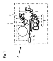
FIG. 1 is a cross-sectional view illustrating a rough configuration of an image forming apparatus in which a toner cartridge according to this embodiment is used; -
FIG. 2A is a perspective view illustrating a toner cartridge according to a first embodiment; -
FIG. 2B is a partial front view illustrating a toner cartridge in which an IC chip holder is attached to a toner container inFIG. 2A ; -
FIG. 2C is a cross-sectional view ofFIG. 2B ; -
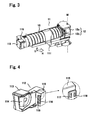
FIG. 3 is a configuration diagram illustrating a main portion of a replenishing device viewed from an arrow A inFIG. 1 ; -
FIG. 4 is a perspective view illustrating a pressing part inFIG. 3 ; -
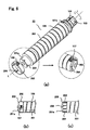
FIGS. 5A, 5B, and 5C are diagrams illustrating operation mechanisms of the toner cartridge and a contact holder; -
FIG. 6A is a perspective view illustrating a toner cartridge according to a second embodiment; -
FIG. 6B is a partial front view illustrating a toner cartridge in which a peripheral ring is fitted to a toner container inFIG. 6A ; -
FIG. 6C is a cross-sectional view ofFIG. 6B ; and -
FIGS. 7A and 7B are diagrams illustrating operation mechanisms of the toner cartridge and the contact holder. - Reference will now be made in detail to the present embodiment of the invention, an example of which is illustrated in the accompanying drawing.
- According to this embodiment, there is provided a toner cartridge including a toner cartridge main body having a cylindrical toner container that contains toner therein, a toner discharge port disposed on one end of the toner container, and a rotating shaft disposed on the other end of the toner container; and an annular IC chip holder that is fitted to the rotating shaft of the toner cartridge main body to rotate together with the toner cartridge main body, and has a notch formed in an outer peripheral surface in which an IC chip is mounted, wherein the IC chip holder rotates together with the toner cartridge main body until the IC chip holder is fixed to an IC chip contact holder having a contact member for contacting a terminal of the IC chip disposed in the image forming apparatus main body.
- Also, according to this embodiment, there is provided a toner cartridge for use in an image forming apparatus, wherein a member of another piece that does not rotate integrally with the toner container is disposed on an outer periphery, and the IC chip of the toner cartridge can be always in contact with the main body side interface substrate even when the bottle rotates during replenishing toner.
- Hereinafter, this embodiment will be described with reference to
FIGS. 1 to 8 . In the following description, the same symbols denote components having the identical configurations and functions. -
FIG. 1 is a diagram illustrating a rough configuration of animage forming part 2 in animage forming apparatus 1 according to this embodiment. Around aphotosensitive drum 3 in theimage forming part 2 are arranged acharging unit 4 that uniformly sequentially charges thephotosensitive drum 3 with rotation of thephotosensitive drum 3 in a direction of an arrow s, anexposure unit 5 that irradiates alaser beam 5a for forming a latent image on the chargedphotosensitive drum 3, a developingdevice 6 that supplies toner to the formed latent image, a transfer and peeling charger 7 that transfers a toner image formed on thephotosensitive drum 3 to a transfer medium, a cleaner 8 that removes untransferred toner from thephotosensitive drum 3, and aneutralization lamp 9 that removes electric charges from thephotosensitive drum 3. - The developing
device 6 is a known developing device of a magnetic brush system which performs development by the aid of a two-component developer containing toner and carrier. Adevelopment roller 6b, atransport auger 6c, and atoner concentration sensor 6d are disposed within adevelopment container 6a. The developingdevice 6 further includes atoner replenishing part 11 that replenishes the developingdevice 6 with toner from atoner cartridge 10 according to a toner concentration in the developer, which is detected by thetoner concentration sensor 6d, at a side end of theimage forming apparatus 1. - As illustrated in
FIG. 2A , thetoner cartridge 10 includes atoner container 101 that contains toner therein as a main body, and anIC chip holder 102. TheIC chip holder 102 is attached to one end of thetoner container 101, and acylindrical cap part 103 is attached to the other end of thetoner container 101. Thecap part 103 is equipped with atoner supply part 104 for supplying toner within thetoner container 101 to thetoner replenishing part 11. Thetoner cartridge 10 is installed in thetoner replenishing part 11, and rotates (as indicated by an arrow t) about an axis (a dotted line L) extending in a longitudinal direction thereof to replenish the developingdevice 6 with toner. - The
toner container 101 is of a substantially cylindrical configuration with a bottom, and a helical protrusion for transporting toner is formed on at least an inner peripheral surface of thetoner container 101, and ahelical groove 105 corresponding to the helical protrusion is formed in an outer peripheral surface thereof. Toner filled in thetoner container 101 in advance is gradually sent to thecap part 103 side with the help of thehelical groove 105 with rotation of thetoner container 101. Toner is then sent from thetoner supply part 104 of thecap part 103 to the developingdevice 6. - A
bottom 101a of thetoner container 101 has a rotatingshaft 101b of a cylindrical configuration smaller than an outer diameter of thetoner container 101, for attaching theIC chip holder 102. On the other hand, a top 101c of thetoner container 101 is smaller than a diameter of thetoner container 101. An outer surface of the top 101c to be connected with thecap part 103 is so threaded as to be engaged with a threaded inner surface of thecap part 103. Those threads are reverse to each other so that thecap part 103 is not detached from the top 101c due to rotation. Thetoner container 101 and thecap part 103 may be integrated with each other. - The
IC chip holder 102 is of a cylindrical configuration (annular shape) having substantially the same diameter as an outer diameter of thetoner container 101, and a substantially L-shapednotch 107 in which anIC chip 106 is located is formed in an outer surface of theIC chip holder 102. Afitting part 102a having a diameter (an arrow β) larger than a diameter (an arrow α) of therotating shaft 101b is provided in the center of theIC chip holder 102. Therotating shaft 101b and thefitting part 102a are fitted to each other through atorque limiter 108. Thetoner container 101 and theIC chip holder 102 freely rotate about the axial line (dotted line L) in the longitudinal direction relative to each other. Also, theIC chip holder 102 is detachably attached to thetoner container 101 in a direction of the axial line (dotted line L) in the longitudinal direction (FIGS. 2B and 2C ). - As illustrated in
FIG. 3 , thetoner replenishing part 11 includes acartridge holding part 111 that detachably holds thetoner cartridge 10, a tonercartridge drive part 12 that rotationally drives thetoner cartridge 10 about an axis thereof, and acartridge pressing part 112 that presses thetoner cartridge 10 toward the tonercartridge drive part 12. - The
cartridge holding part 111 is rotatably supported about a portion connected with theimage forming apparatus 1 as an axis (dotted line M) (arrows Q, R) . Thetoner cartridge 10 is attached or detached by using the rotating operation (arrows Q, R) of thecartridge holding part 111. Specifically, if thetoner cartridge 10 is loaded in theimage forming apparatus 1, after the user holds thetoner cartridge 10 in thecartridge holding part 111, the user rotates thecartridge holding part 111 in a direction of an arrow Q. On the other hand, if thetoner cartridge 10 is removed, the user rotates thecartridge holding part 111 in a direction of an arrow R, and projects thecartridge holding part 111 to an outside of theimage forming apparatus 1. - The toner
cartridge drive part 12 includes a drive partmain body 12a and acoupling 12b, and is disposed in the vicinity of a coupling part of thetoner replenishing part 11. Thecoupling 12b is cylindrical, and a bottom of thecoupling 12b has a convexo-concave part formed to be fitted to a convexo-concave part formed on a top of thecap part 103. - As illustrated in
FIG. 4 , thecartridge pressing part 112 includes afixed part 113 fixed to theimage forming apparatus 1, and apressing part 114. An urging member such as a spring is disposed between thefixed part 113 and thepressing part 114, and urged in a direction of thetoner cartridge 10. Also, thefixed part 113 includes an ICchip contact holder 115 with a cartridge interface substrate. - The IC
chip contact holder 115 has astep 116 for fixing theIC chip holder 102. Thestep 116 hasslits 117, andcontact members 118 such as contact springs for contacting electrodes of theIC chip 106 located in theIC chip holder 102 are projected from theslits 117. Thecontact members 118 are covered with an insulating member except for a portion contacting the electrodes of theIC chip 106, connects with the cartridge interface substrate, and exchange information about thetoner cartridge 10 with theimage forming apparatus 1 main body through the cartridge interface substrate. - With the configuration described above, the
toner cartridge 10 rotates upon receiving a drive force from theimage forming apparatus 1 . TheIC chip holder 102 rotates together with rotation of thetoner container 101 by means of thetorque limiter 108. Thereafter, if a given load or more is applied to theIC chip holder 102, theIC chip holder 102 runs over with respect to rotation of thetoner container 101. - Specifically, the
toner container 101 first rotates by a given amount when the user exchanges thetoner cartridge 10 with a fresh one (FIG. 5A ; an arrow t1), and theIC chip holder 102 also rotates together with rotation of the toner container 101 (FIG. 5A ; an arrow t2). Thereafter, thenotch 107 in which theIC chip 106 is located on theIC chip holder 102 arrives at thestep 116, and is then locked (caught) . At the same time, thecontact members 118 contacts the IC chip 106 (FIG. 5C ). TheIC chip holder 102 is fixed at a locked position, runs over with respect to rotation of thetoner container 101, and thereafter only thetoner container 101 continuously rotates (FIG. 5B ; an arrow t1). InFIGS. 5A and 5B , thetoner cartridge 10 is illustrated by a cross section along a chain line B-B' ofFIG. 2C . - When the
IC chip holder 102 is thus fixed at the above-mentioned locked position with the help of thenotch 107 and thestep 116 of the ICchip contact holder 115, the electrodes of theIC chip 106 always contact thecontact members 118. In this situation, information is always exchanged between the main body side and the toner cartridge. - Subsequently, a
toner cartridge 20 according to a second embodiment will be described with reference toFIG. 6 . Thetoner cartridge 20 can be filled with toner more than that in thetoner cartridge 10 of the first embodiment. In the following description, the same parts as those in thetoner cartridge 10 of the first embodiment will be omitted from description. - The
toner cartridge 20 according to this embodiment includes atoner container 201 that contains toner therein as a main body, and an outerperipheral ring 202 as an IC chip holder. Thetoner container 201 includes a bottom 201a having a diameter smaller than that of thetoner container 201 by one step. - The bottom 201a has the same function as that of the
rotating shaft 101b in thetoner cartridge 10. Also, thebottom 201a is provided withprojections 203 for supporting an outerperipheral ring 202 attached thereto so as not to be removed. The interiors of thetoner container 201 and thebottom 201a communicate with each other. - The outer
peripheral ring 202 is disposed on an outer peripheral surface of the bottom 201a so as to be slidable (detachable) along an axial direction. The outerperipheral ring 202 has thenotch 107 in which theIC chip 106 is located as with theIC chip holder 102 in thetoner cartridge 10.Contact members 204 such as brushes or plate springs are attached to an inner wall of the outerperipheral ring 202, and the outerperipheral ring 202 is attached to the bottom 201a through thecontact members 204. - With the above configuration, the
toner cartridge 20 can be filled with much toner for the bottom 201a as compared with thetoner cartridge 10. - The installation location of the outer
peripheral ring 202 is not particularly limited, but is preferably a position farthest from thetoner supply part 104, that is, a bottom of thetoner container 201 illustrated inFIG. 7 , from the viewpoint of preventing fly toner from being attached to theIC chip 106. - A specific operation mechanism of the
toner cartridge 20 will be described with reference toFIG. 7 . First, when the user exchanges thetoner cartridge 20 with a fresh one, thetoner container 201 rotates by a given amount, and the outerperipheral ring 202 also rotates together with rotation of the toner container 201 (FIG. 7A ; arrows t1 and t2). Thereafter, thenotch 107 in which theIC chip 106 is located on the outerperipheral ring 202 arrives at thestep 116 of the ICchip contact holder 115, and is then locked (caught). At the same time, thecontact members 118 contacts with theIC chip 106. The outerperipheral ring 202 is fixed at a locked position, runs over with respect to rotation of thetoner container 201, and thereafter only thetoner container 101 continuously rotates (FIG. 7B ; the arrow t1). - As described above, according to this embodiment, even if the toner cartridge is rotating when toner is replenished, the IC chip of the toner cartridge can always contact the main body side cartridge interface substrate, and information can be exchanged between the toner cartridge and the image forming apparatus main body.
- While certain embodiments have been described, these embodiments have been presented by way of example only, and are not intended to limit the scope of the inventions. Indeed, the novel embodiments described herein may be embodied in a variety of other forms; furthermore, various omissions, substitutions and changes in the form of the embodiments described herein may be made without departing from the spirit of the inventions the accompanying claims and their equivalents are intended to cover such forms or modifications as would fall within the scope and spirit of the inventions.
Claims (20)
- A toner cartridge, comprising:a toner cartridge main body having a cylindrical toner container that contains toner therein, a toner discharge port disposed on one end of the toner container, and a rotating shaft disposed on the other end of the toner container; andan annular IC chip holder that is fitted to the rotating shaft of the toner cartridge main body to rotate together with the toner cartridge main body, and has a notch formed in an outer peripheral surface in which an IC chip is mounted, whereinthe IC chip holder rotates together with the toner cartridge main body until the IC chip holder is fixed to an IC chip contact holder having a contact member for contacting a terminal of the IC chip disposed in the image forming apparatus main body.
- The cartridge according to claim 1, wherein
a helical protrusion is formed on an inner peripheral surface of the toner container so that toner in the toner container moves toward the toner discharge port due to rotation of the toner cartridge. - The cartridge according to claim 1, wherein
the notch of the annular IC chip holder is substantially L-shaped in a cross section perpendicular to a rotating shaft of the toner cartridge. - The cartridge according to claim 1, wherein
the IC chip holder is attached to a rotating shaft of the toner container through a torque limiter. - A toner cartridge, comprising:a toner cartridge main body including a cylindrical toner container that contains toner therein, a toner discharge port provided at one end of the toner container, and a rotating shaft disposed at the other end of the toner container, in which an interior of the rotating shaft is hollow, and communicates with an interior of the toner container; andan annular IC chip holder that is fitted to the rotating shaft of the toner cartridge main body to rotate together with the toner cartridge main body, and has a notch formed on an outer periphery thereof in which an IC chip is mounted, whereinthe IC chip holder rotates together with the toner cartridge main body until the IC chip holder is fixed to an IC chip contact holder having a contact member for contacting a terminal of the IC chip, which is disposed in an image forming apparatus main body.
- The cartridge according to claim 5, wherein
a helical projection is formed on an inner peripheral surface of the toner container so that toner within the toner container moves toward the toner discharge port due to rotation of the toner cartridge. - The cartridge according to claim 5, wherein
the notch of the annular IC chip holder is substantially L-shaped in a cross section perpendicular to a rotating shaft of the toner cartridge. - The cartridge according to claim 5, wherein
the IC chip holder is attached to the bottom through a brush. - The cartridge according to claim 5, wherein
the IC chip holder is attached to a rotating shaft of the toner container through a spring. - An image forming apparatus, comprising:a developing device that forms a toner image on an electrostatic latent image formed on an image carrier;a toner cartridge including a toner cartridge main body having a cylindrical toner container that contains toner to be supplied to the developing device therein, a toner discharge port provided at one end of the toner container, and a rotating shaft disposed at the other end of the toner container, and an annular IC chip holder that is fitted to the rotating shaft of the toner cartridge main body to rotate together with the toner cartridge main body, and has an outer peripheral surface formed with a notch in which an IC chip is mountable;a toner cartridge holding part that holds the toner cartridge so as to be detachable and rotatable about a center axis of the cylindrical toner container; andan IC chip contact holder including a step that is fixed to the toner cartridge holding part, and stops rotation of the IC chip holder when being engaged with the notch of the IC chip holder during rotation of the IC chip holder, and a contact member for contacting a terminal of the IC chip.
- The apparatus according to claim 10, wherein
a helical projection is formed on an inner peripheral surface of the toner container so that toner within the toner container moves toward the toner discharge port due to rotation of the toner cartridge. - The apparatus according to claim 10, wherein
the notch of the annular IC chip holder is substantially L-shaped in a cross section perpendicular to a rotating shaft of the toner cartridge. - The apparatus according to claim 10, wherein
the IC chip holder is attached to a rotating shaft of the toner container through a torque limiter. - The apparatus according to claim 10, wherein
an interior of the rotating shaft is hollow, communicates with an interior of the toner container, and the toner can be contained in the interior of the rotating shaft. - The apparatus according to claim 14, wherein
a helical projection is formed on an inner peripheral surface of the toner container so that toner within the toner container moves toward the toner discharge port due to rotation of the toner cartridge. - The apparatus according to claim 14, wherein
the notch of the annular IC chip holder is substantially L-shaped in a cross section perpendicular to a rotating shaft of the toner cartridge. - The apparatus according to claim 14, wherein
the IC chip holder is attached to the bottom through a brush. - The apparatus according to claim 14, wherein
the IC chip holder is attached to a rotating shaft of the toner container through a spring. - A toner cartridge used in the apparatus of claim 10, comprising:a toner cartridge main body having a cylindrical toner container that contains toner therein, a toner discharge port provided at one end of the toner container, and a rotating shaft disposed at the other end of the toner container; andan annular IC chip holder that is fitted to the rotating shaft of the toner cartridge main body to rotate together with the toner cartridge main body, and has an outer peripheral surface formed with a notch in which an IC chip is mountable.
- The cartridge used in the apparatus of claim 14, wherein
a toner cartridge main body including a cylindrical toner container that contains toner therein, a toner discharge port provided at one end of the toner container, and a rotating shaft disposed at the other end of the toner container, in which an interior of the rotating shaft is hollow, and communicates with an interior of the toner container; and
an annular IC chip holder that is fitted to the rotating shaft of the toner cartridge main body to rotate together with the toner cartridge main body, and has a notch formed on an outer periphery thereof in which an IC chip is mounted.
Applications Claiming Priority (1)
| Application Number | Priority Date | Filing Date | Title |
|---|---|---|---|
| US30994410P | 2010-03-03 | 2010-03-03 |
Publications (1)
| Publication Number | Publication Date |
|---|---|
| EP2367068A2 true EP2367068A2 (en) | 2011-09-21 |
Family
ID=44247531
Family Applications (1)
| Application Number | Title | Priority Date | Filing Date |
|---|---|---|---|
| EP11155639A Withdrawn EP2367068A2 (en) | 2010-03-03 | 2011-02-23 | Toner cartridge |
Country Status (5)
| Country | Link |
|---|---|
| US (1) | US20110217067A1 (en) |
| EP (1) | EP2367068A2 (en) |
| JP (1) | JP5526058B2 (en) |
| KR (1) | KR20110100149A (en) |
| CN (1) | CN102193404A (en) |
Cited By (5)
| Publication number | Priority date | Publication date | Assignee | Title |
|---|---|---|---|---|
| EP2911007A1 (en) * | 2014-02-19 | 2015-08-26 | Xerox Corporation | Systems and methods for mounting an externally readable monitoring module on a rotating customer replaceable component in an operating device |
| WO2020046326A1 (en) * | 2018-08-30 | 2020-03-05 | Hewlett-Packard Development Company, L.P. | Electrical contacts coupled to guide structures |
| WO2020046334A1 (en) * | 2018-08-30 | 2020-03-05 | Hewlett-Packard Development Company, L.P. | Print particle replenishment device |
| WO2020046339A1 (en) * | 2018-08-30 | 2020-03-05 | Hewlett-Packard Development Company, L.P. | Contacts for a print particle input recess |
| US11865845B2 (en) | 2018-08-30 | 2024-01-09 | Hewlett-Packard Development Company, L.P. | Print material refill device |
Families Citing this family (20)
| Publication number | Priority date | Publication date | Assignee | Title |
|---|---|---|---|---|
| JP5574546B2 (en) * | 2012-03-29 | 2014-08-20 | 京セラドキュメントソリューションズ株式会社 | Image forming apparatus and removable developer container mounted thereon |
| JP6031892B2 (en) * | 2012-08-23 | 2016-11-24 | 株式会社リコー | Image forming apparatus |
| CN203573089U (en) * | 2013-11-11 | 2014-04-30 | 珠海赛纳打印科技股份有限公司 | Developing box |
| JP5743359B2 (en) * | 2014-06-11 | 2015-07-01 | 京セラドキュメントソリューションズ株式会社 | Image forming apparatus and removable developer container mounted thereon |
| JP5743360B2 (en) * | 2014-06-11 | 2015-07-01 | 京セラドキュメントソリューションズ株式会社 | Image forming apparatus and removable developer container mounted thereon |
| CN107020826B (en) * | 2016-01-29 | 2019-01-15 | 理想科学工业株式会社 | The method of reproducing of label stripping means and print cartridge on print cartridge, the box |
| JP6583149B2 (en) | 2016-06-08 | 2019-10-02 | 京セラドキュメントソリューションズ株式会社 | Toner container and image forming apparatus |
| JP6504115B2 (en) | 2016-06-08 | 2019-04-24 | 京セラドキュメントソリューションズ株式会社 | Toner container, image forming apparatus |
| JP6520833B2 (en) | 2016-06-08 | 2019-05-29 | 京セラドキュメントソリューションズ株式会社 | Toner container, image forming apparatus |
| JP6512177B2 (en) | 2016-06-08 | 2019-05-15 | 京セラドキュメントソリューションズ株式会社 | Image forming apparatus provided with toner container |
| US10095159B2 (en) * | 2017-01-19 | 2018-10-09 | Kabushiki Kaisha Toshiba | Image forming apparatus and method for acquiring information of toner container |
| KR20190125106A (en) * | 2018-04-27 | 2019-11-06 | 휴렛-팩커드 디벨롭먼트 컴퍼니, 엘.피. | Supplying refill toner to mounted toner cartridge |
| KR20200025348A (en) * | 2018-08-30 | 2020-03-10 | 휴렛-팩커드 디벨롭먼트 컴퍼니, 엘.피. | Toner refill cartridge with holder holding memory unit thereon and rotatable with respect to cartridge body |
| KR102390147B1 (en) * | 2018-08-30 | 2022-04-25 | 휴렛-팩커드 디벨롭먼트 컴퍼니, 엘.피. | Toner refill cartridge connected to main body through interface between development cartridge and main body |
| CN112262348B (en) * | 2018-08-30 | 2023-06-30 | 惠普发展公司,有限责任合伙企业 | Contact pad for a printing particle replenishment device |
| KR20200025336A (en) * | 2018-08-30 | 2020-03-10 | 휴렛-팩커드 디벨롭먼트 컴퍼니, 엘.피. | Structure for selectively locking toner inlet shutter of toner refill portion |
| US10482452B1 (en) * | 2019-01-24 | 2019-11-19 | Capital One Services, Llc | Payment apparatus |
| CN110658704A (en) * | 2019-09-04 | 2020-01-07 | 江西凯利德科技有限公司 | Novel developer supply container and developer supply method |
| JP7512732B2 (en) | 2020-07-21 | 2024-07-09 | 株式会社リコー | Image forming apparatus and toner storage container |
| CN116113889A (en) * | 2020-09-28 | 2023-05-12 | 惠普发展公司,有限责任合伙企业 | Toner refill cartridge with collapsible plunger |
Family Cites Families (15)
| Publication number | Priority date | Publication date | Assignee | Title |
|---|---|---|---|---|
| JP3600391B2 (en) * | 1997-01-07 | 2004-12-15 | 株式会社リコー | Image forming device |
| JP4016682B2 (en) * | 2002-03-19 | 2007-12-05 | 富士ゼロックス株式会社 | Toner cartridge mounting state detection device |
| JP3778110B2 (en) * | 2002-03-19 | 2006-05-24 | 富士ゼロックス株式会社 | Wireless communication system, image forming apparatus, and cartridge part |
| JP4147832B2 (en) * | 2002-06-17 | 2008-09-10 | 富士ゼロックス株式会社 | Wireless communication system, image forming apparatus, and cartridge part |
| CN100440065C (en) * | 2004-10-18 | 2008-12-03 | 株式会社理光 | Image forming device and mounting member for mounting a toner container thereon |
| JP4557809B2 (en) * | 2005-02-22 | 2010-10-06 | 株式会社リコー | Image forming apparatus |
| US7447469B2 (en) * | 2004-10-18 | 2008-11-04 | Ricoh Company, Ltd. | Image forming device and mounting member for mounting a toner container thereon |
| JP4574468B2 (en) * | 2004-11-30 | 2010-11-04 | 株式会社リコー | Image forming apparatus |
| PL2796936T3 (en) * | 2005-03-04 | 2016-11-30 | Developer supply container and developer supplying system | |
| TWI594090B (en) * | 2005-04-27 | 2017-08-01 | 理光股份有限公司 | Toner container and image forming device |
| JP2007065368A (en) * | 2005-08-31 | 2007-03-15 | Toshiba Corp | Toner cartridge |
| US7483659B2 (en) * | 2005-08-31 | 2009-01-27 | Kabushiki Kaisha Toshiba | Toner cartridge and image forming apparatus for mounting the same |
| JP4566147B2 (en) * | 2006-03-06 | 2010-10-20 | シャープ株式会社 | Toner container and toner filling method |
| JP4910793B2 (en) * | 2007-03-12 | 2012-04-04 | ブラザー工業株式会社 | Developer cartridge |
| US20090110417A1 (en) * | 2007-10-29 | 2009-04-30 | Kabushiki Kaisha Toshiba | Image forming apparatus |
-
2011
- 2011-02-23 EP EP11155639A patent/EP2367068A2/en not_active Withdrawn
- 2011-02-23 US US13/032,726 patent/US20110217067A1/en not_active Abandoned
- 2011-02-24 KR KR1020110016303A patent/KR20110100149A/en not_active Abandoned
- 2011-03-02 CN CN2011100503100A patent/CN102193404A/en active Pending
- 2011-03-03 JP JP2011046080A patent/JP5526058B2/en not_active Expired - Fee Related
Cited By (10)
| Publication number | Priority date | Publication date | Assignee | Title |
|---|---|---|---|---|
| EP2911007A1 (en) * | 2014-02-19 | 2015-08-26 | Xerox Corporation | Systems and methods for mounting an externally readable monitoring module on a rotating customer replaceable component in an operating device |
| WO2020046326A1 (en) * | 2018-08-30 | 2020-03-05 | Hewlett-Packard Development Company, L.P. | Electrical contacts coupled to guide structures |
| WO2020046334A1 (en) * | 2018-08-30 | 2020-03-05 | Hewlett-Packard Development Company, L.P. | Print particle replenishment device |
| WO2020046339A1 (en) * | 2018-08-30 | 2020-03-05 | Hewlett-Packard Development Company, L.P. | Contacts for a print particle input recess |
| CN112041762A (en) * | 2018-08-30 | 2020-12-04 | 惠普发展公司,有限责任合伙企业 | Printing particle supplementing device |
| US11305547B2 (en) | 2018-08-30 | 2022-04-19 | Hewlett-Packard Development Company, L.P. | Electrical contacts coupled to guide structures |
| US11454921B2 (en) | 2018-08-30 | 2022-09-27 | Hewlett-Packard Development Company, L.P. | Contacts for a print particle input recess |
| US11571854B2 (en) | 2018-08-30 | 2023-02-07 | Hewlett-Packard Development Company, L.P. | Print particle replenishment device |
| US11865845B2 (en) | 2018-08-30 | 2024-01-09 | Hewlett-Packard Development Company, L.P. | Print material refill device |
| EP3762237B1 (en) * | 2018-08-30 | 2025-04-02 | Hewlett-Packard Development Company, L.P. | Print materials replenishment |
Also Published As
| Publication number | Publication date |
|---|---|
| KR20110100149A (en) | 2011-09-09 |
| JP2011180598A (en) | 2011-09-15 |
| JP5526058B2 (en) | 2014-06-18 |
| CN102193404A (en) | 2011-09-21 |
| US20110217067A1 (en) | 2011-09-08 |
Similar Documents
| Publication | Publication Date | Title |
|---|---|---|
| US20110217067A1 (en) | Toner cartridge | |
| JP3541691B2 (en) | Image forming apparatus and developer container | |
| CN1303482C (en) | Developer supply container and electrophotographic image forming apparatus | |
| US9170530B2 (en) | Powder container and image forming apparatus incorporating same | |
| JP4380639B2 (en) | Toner container, image forming apparatus, and toner container manufacturing method | |
| JP6213706B2 (en) | Developer container and image forming apparatus | |
| US9354586B2 (en) | Communication connector and image forming apparatus | |
| JPH10105012A (en) | Cleaning device and process cartridge | |
| JP5526103B2 (en) | Developer container and image forming apparatus to which the container is applied | |
| US20150063834A1 (en) | Image forming apparatus | |
| EP2230569A2 (en) | Image forming apparatus | |
| US11782378B2 (en) | Image forming apparatus provided with detachable processing unit | |
| JP5273263B2 (en) | Developer container, developing device, process unit, and image forming apparatus | |
| KR20120117650A (en) | Developer container and image forming device equipped with the same | |
| CN1932677A (en) | Image forming apparatus | |
| JP2001075457A (en) | Process cartridge and image forming apparatus | |
| JP4882516B2 (en) | Process unit and developer cartridge | |
| CN204576059U (en) | developer supply container | |
| JP4805073B2 (en) | Developer supply device and image forming apparatus | |
| JPH09106160A (en) | Toner supply device | |
| JP6069879B2 (en) | Image forming apparatus | |
| JP4308631B2 (en) | Development device | |
| JP7209205B2 (en) | Development cartridge and image forming apparatus | |
| CN110865523B (en) | Toner container and image forming apparatus | |
| JP2008003434A (en) | Image carrier toner unit and image forming apparatus |
Legal Events
| Date | Code | Title | Description |
|---|---|---|---|
| PUAI | Public reference made under article 153(3) epc to a published international application that has entered the european phase |
Free format text: ORIGINAL CODE: 0009012 |
|
| 17P | Request for examination filed |
Effective date: 20110223 |
|
| AK | Designated contracting states |
Kind code of ref document: A2 Designated state(s): AL AT BE BG CH CY CZ DE DK EE ES FI FR GB GR HR HU IE IS IT LI LT LU LV MC MK MT NL NO PL PT RO RS SE SI SK SM TR |
|
| AX | Request for extension of the european patent |
Extension state: BA ME |
|
| STAA | Information on the status of an ep patent application or granted ep patent |
Free format text: STATUS: THE APPLICATION HAS BEEN WITHDRAWN |
|
| 18W | Application withdrawn |
Effective date: 20130129 |