EP2367037A2 - Optical cable with controlled fiber positioning - Google Patents
Optical cable with controlled fiber positioning Download PDFInfo
- Publication number
- EP2367037A2 EP2367037A2 EP11158852A EP11158852A EP2367037A2 EP 2367037 A2 EP2367037 A2 EP 2367037A2 EP 11158852 A EP11158852 A EP 11158852A EP 11158852 A EP11158852 A EP 11158852A EP 2367037 A2 EP2367037 A2 EP 2367037A2
- Authority
- EP
- European Patent Office
- Prior art keywords
- channel
- cable
- fiber optic
- optic cable
- optical fiber
- Prior art date
- Legal status (The legal status is an assumption and is not a legal conclusion. Google has not performed a legal analysis and makes no representation as to the accuracy of the status listed.)
- Granted
Links
- 239000000835 fiber Substances 0.000 title claims abstract description 68
- 230000003287 optical effect Effects 0.000 title description 5
- 239000013307 optical fiber Substances 0.000 claims abstract description 101
- 239000004020 conductor Substances 0.000 claims abstract description 57
- 239000000463 material Substances 0.000 claims description 19
- 229920000642 polymer Polymers 0.000 claims description 17
- 239000004760 aramid Substances 0.000 claims description 3
- 229920003235 aromatic polyamide Polymers 0.000 claims description 3
- 238000000034 method Methods 0.000 abstract description 5
- 239000013536 elastomeric material Substances 0.000 description 13
- 238000005452 bending Methods 0.000 description 7
- 229920002725 thermoplastic elastomer Polymers 0.000 description 7
- 229920002803 thermoplastic polyurethane Polymers 0.000 description 6
- 239000011810 insulating material Substances 0.000 description 4
- 230000002093 peripheral effect Effects 0.000 description 4
- 239000004800 polyvinyl chloride Substances 0.000 description 3
- 239000000654 additive Substances 0.000 description 1
- 230000002411 adverse Effects 0.000 description 1
- 150000001875 compounds Chemical class 0.000 description 1
- 238000005336 cracking Methods 0.000 description 1
- 239000003063 flame retardant Substances 0.000 description 1
- 230000001788 irregular Effects 0.000 description 1
- 239000000203 mixture Substances 0.000 description 1
- 229920005989 resin Polymers 0.000 description 1
- 239000011347 resin Substances 0.000 description 1
Images


Classifications
-
- G—PHYSICS
- G02—OPTICS
- G02B—OPTICAL ELEMENTS, SYSTEMS OR APPARATUS
- G02B6/00—Light guides; Structural details of arrangements comprising light guides and other optical elements, e.g. couplings
- G02B6/44—Mechanical structures for providing tensile strength and external protection for fibres, e.g. optical transmission cables
- G02B6/4401—Optical cables
- G02B6/4415—Cables for special applications
- G02B6/4416—Heterogeneous cables
-
- G—PHYSICS
- G02—OPTICS
- G02B—OPTICAL ELEMENTS, SYSTEMS OR APPARATUS
- G02B6/00—Light guides; Structural details of arrangements comprising light guides and other optical elements, e.g. couplings
- G02B6/44—Mechanical structures for providing tensile strength and external protection for fibres, e.g. optical transmission cables
- G02B6/4401—Optical cables
- G02B6/4407—Optical cables with internal fluted support member
-
- G—PHYSICS
- G02—OPTICS
- G02B—OPTICAL ELEMENTS, SYSTEMS OR APPARATUS
- G02B6/00—Light guides; Structural details of arrangements comprising light guides and other optical elements, e.g. couplings
- G02B6/44—Mechanical structures for providing tensile strength and external protection for fibres, e.g. optical transmission cables
- G02B6/4401—Optical cables
- G02B6/4429—Means specially adapted for strengthening or protecting the cables
- G02B6/443—Protective covering
- G02B6/4432—Protective covering with fibre reinforcements
-
- H—ELECTRICITY
- H01—ELECTRIC ELEMENTS
- H01B—CABLES; CONDUCTORS; INSULATORS; SELECTION OF MATERIALS FOR THEIR CONDUCTIVE, INSULATING OR DIELECTRIC PROPERTIES
- H01B11/00—Communication cables or conductors
- H01B11/22—Cables including at least one electrical conductor together with optical fibres
Definitions
- the present disclosure generally relates to fiber optic cables and methods of controlling a position of an optical fiber within the fiber optic cable.
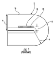
- FIG. 1 shows a typical fiber optic cable in a bent back configuration.
- the fiber optic cable 2 is generally circular and has an outer bend periphery 16 and a cable diameter or thickness 6 .
- an optical fiber 10 Internal to the cable is an optical fiber 10 , which carries data.
- a bend radius 8 is at a minimum and is approximately equal to the cable diameter 6 .
- the location of the optical fiber 10 within the cable 2 will affect a bend radius 12 of the optical fiber 10. If the optical fiber 10 is close to the outer bend periphery 16 , the fiber will have a larger bend radius and experience lower attenuation.
- the bend radius of the fiber will be smaller and cause greater delta attenuation due bending. If the bend radius 12 is small enough, the optical fiber may crack at an outer surface 18 of the optical fiber 10 and cause cracking or fracture of the optical fiber 10 .
- a fiber optic cable comprises a polymer jacket having a channel therein, the channel having a first slot, at least one optical fiber in the first slot, a first electrical conductor, and a second electrical conductor.
- the optical fiber is positioned in the first slot and remains within the first slot when the fiber optic cable is bent a maximum amount such that a bend radius of the optical fiber is greater than or equal to a minimum bend radius of the optical fiber.
- the cable may have first and second preferential bend axes such that when the cable is bent back about either axis, the optical fibers are bent at bend radii exceeding their minimum bend radii.
- the cable can have a round cross-section with a diameter in the range of 2.8-3.2 millimeters, and the geometric center of the first slot can be within 0.2 millimeters of the geometric center of the cable.
- a fiber optic cable comprises a polymer jacket having a channel therein, at least one optical fiber in the channel, a first electrical conductor on a first side of the channel, and a second electrical conductor on a second side of the channel.
- the optical fiber is positioned in the channel and remains within the channel when the fiber optic cable is bent a maximum amount such that a bend radius of the optical fiber is greater than or equal to a minimum bend radius of the optical fiber.
- the cable may have a preferential bend axis aligned with the channel such that when the cable is bent back about the channel, the optical fibers are bent at bend radii exceeding their minimum bend radii.
- the cable can have a round cross-section with a diameter in the range of 2.8-3.2 millimeters, and the geometric center of the channel can be within 0.2 millimeters of the geometric center of the cable.
- a fiber optic cable comprises a polymer jacket having a channel therein and a diameter in the range of 2.8-3.2 millimeters, the channel having a width at least twice as large as a height of the channel, at least one optical fiber in the channel, and a strength material disposed within the channel and contacting the at least one optical fiber.
- the optical fiber is positioned in the channel and remains within the channel when the fiber optic cable is bent a maximum amount such that a bend radius of the optical fiber is greater than or equal to a minimum bend radius of the optical fiber.
- the geometric center of the channel can be within 0.2 millimeters of the geometric center of the cable.
- FIG. 1 is a cross-sectional view of a typical prior art fiber optic cable in a bent back configuration, wherein the cross-section is parallel to a length of the cable.
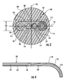
- FIG. 2 is a cross-sectional view of a fiber optic cable according to an embodiment of this disclosure, wherein the cross-section is a transverse cross-section perpendicular to a length of the cable.
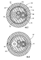
- FIG. 3 is a transverse cross-sectional view of a fiber optic cable according to another embodiment of this disclosure.
- FIG. 4 is a side view of the fiber optic cable of FIG. 3 being bent about an axis having a maximum moment of inertia.
- FIG. 5 is a transverse cross-sectional view of a fiber optic cable according to another embodiment of this disclosure.
- FIG. 6 is a transverse cross-sectional view of a fiber optic cable according to another embodiment of this disclosure.
- FIG. 7 is a transverse cross-sectional view of a fiber optic cable according to another embodiment of this disclosure.
- FIG. 8 is a transverse cross-sectional view of a fiber optic cable according to another embodiment of this disclosure.
- the fiber optic cables described herein may include a plurality of optical fibers arranged with little or no stranding or twisting around each other.
- FIG. 2 is a cross-sectional view of a fiber optic cable 30 according to a first embodiment of this disclosure.
- the cable 30 includes a polymer jacket 32 having an outer periphery 34 and a channel periphery 36 with the channel periphery 36 defining a channel 38.
- the cross-section of the cable 30 is generally circular with a diameter of about 3.0 millimeters (mm).
- mm millimeters
- references to diameters and radii of circular cables refer to median or average values.
- polymer and “polymeric” indicate materials comprised primarily of polymers, but allow for the inclusion of non-polymer additives and other materials, such as fire-retardant compounds, etc., and the inclusion of multiple polymers in a blend.
- the polymer jacket 32 encloses the channel 38 and the channel 38 may extend the entire length of the cable 30.
- the cable 30 further includes a pair of metallic electrical conductors 40, 42 that supply power to peripheral electrical equipment.
- the electrical conductors 40, 42 can in addition or alternatively carry data.
- the electrical conductors 40, 42 may be surrounded by insulating material 44, 46 respectively.
- the electrical conductors 40, 42 can be embedded in the jacket 32 so that insulating material can be omitted.
- Data-carrying optical fibers 48, 50 are also included within the cable 30 .
- the optical fibers 48, 50 may be surrounded by buffer layers 58, 60 , respectively.
- the electrical conductors 40, 42 and the buffered optical fibers 48, 50 are positioned within the channel 38 . Additional conductors can be wholly or partially embedded within the jacket 32.
- the optical fibers 48, 50 are generally allowed to translate within the channel 38 when the cable 30 is bent.
- the optical fibers 48, 50 can translate in the channel 38 along a first axis 52 that is perpendicular to a first axis 54 along which the electrical conductors 40, 42 are generally aligned.
- the channel 38 has a "height" or length dimension 56 along the axis 52 through which the fibers can translate.
- the channel 38 is "cross" or “T” shaped, and the cable 30 has a geometric center 62 generally located at the intersection of the axes 52, 54 .
- the optical fibers 40, 42 are arranged in a first slot 72 , which is aligned with the axis 52 , and the electrical conductors 40, 42 are arranged in a second slot 74, which is aligned with to the axis 54 .
- the slots 72, 74 are defined in part by four projections 76 that extend radially inward into the channel 38 .
- the projections 76 may have the form of rounded corners.
- the shape of the slots 72, 74 and the location of the electrical conductors 40, 42 provide some degree of a preferential bend characteristic to the cable 30 to bend either about the axis 52 or the axis 54, as well as allowing the optical fibers 48, 50 to translate to locations to increase their bend radius and reduce optical attenuation.
- the shape of the channel 38 minimizes the material moments of inertia about the axis 54, and accordingly generally induces the cable 30 to bend about axis 54 when the cable 30 is subjected to bending moments. If the cable 30 is bent back about the axis 54 , the optical fibers 48, 50 will undergo a bend radius approximately equal to or greater than the cable radius 64.
- the optical fibers can be selected so that when the cable is bent back about the axis 54 , which is aligned with the slot 72 , the optical fibers do not experience undue optical attenuation.
- the optical fibers 48, 50 may have a minimum bend radius of about 1.5 mm that results in an acceptable delta attenuation in the range of about 1.5 dB to 2.0 dB.
- the exemplary cable radius 64, corresponding to the bend back radius, is about 1.5 mm, so that the optical fibers 48, 50 are not bent at a radius smaller than their minimum bend radius when bending about axis 54 .
- the optical fibers are allowed to translate in the slot 72 so that the fibers 48, 50 do not bend at a radius below their minimum bend radius. For example, if the cable 30 is bent back about axis 54 so that a location 66 on the cable 30 is where the cable is bent back upon itself, the optical fibers will translate "downwardly" in the slot 72, away from the bend back location 66 , to the orientation shown in FIG. 2 . The optical fiber 48 will move away from location 66, toward the "bottom" of the slot 72 , where the fiber 48 is at its lowest strain state. The optical fiber 50 will also move away from the bend back location 66 toward a state of low strain.
- the height 56 of the slot 72 is selected so that optical fibers in the slot do not bend at a radius below their minimum bend radius.
- the height 56 of the slot 72 in the exemplary embodiment is about 1.5 mm, so that when the cable 30 is in bend back, the optical fiber closest to the bend back location is bent at a radius of at least 1.5 mm.
- the preferential bend characteristic of the cable 30 prevents the optical fibers 48, 50 in the cable 30 from bending below their minimum bend radii.
- the electrical conductors 40, 42 are constrained within the slot 74 to prevent crossover with the optical fibers 48, 50, which reduces the likelihood of the fibers from moving out of their slot 72 .
- a geometric center of the slot 72 can correspond to the geometric center 62 of the cable 30 , which can have a round cross-section, or the geometric center of the slot 72 can be within 0.2 mm of the center of the cable 30.
- the illustrated optical fibers 48, 50 include buffer layers 58, 60, buffer layers are not required for the optical fibers illustrated in this specification.
- a cable 30 as shown in FIG. 2 has a diameter in the range of 2.8-3.2 mm, a slot 72 having a dimension 56 in the range of 1.2-1.8 mm, and two electrical conductors in the range of 24 to 28 AWG (American wire gauge).
- the electrical conductors 40, 42 are located on opposite sides of the slot 72 , and their centerlines are spaced from one another a distance in the range of 1.2 to 1.75 mm.
- the cable jacket 102 is comprised primarily of thermoplastic urethane (TPU), thermoplastic elastomer (TPE), or polyvinylchloride (PVC).
- FIG. 3 is a schematic cross-sectional view of a fiber optic cable 100 according to another embodiment of this disclosure.
- the cable 100 includes a polymer jacket 102 having an outer periphery 104 and a channel periphery 106 with the channel periphery 106 defining a channel 124.
- a cross-section of the illustrated cable 100 is generally circular and has a diameter of less than about 3.0 millimeters (mm).
- the jacket 102 surrounds the channel 124 and the channel 124 may extend the entire length of the cable 100.
- the cable 100 further includes a plurality of electrical conductors 108, 110 that may supply power to peripheral equipment.
- the electrical conductors 108, 110 are each surrounded by an insulating material 112, 114 respectively, although the insulating material may be omitted in some embodiments.
- the conductors 108, 110 can be wholly or partially embedded in the jacket 102 at each end of the channel 124.
- Data-carrying buffered optical fibers 116, 118 are also included within the cable 100 , disposed between the electrical conductors 108, 100.
- the optical fibers 116, 118 are also each surrounded by buffer layers 120, 122, respectively.
- the electrical conductors 108, 110 and the buffered optical fibers 116 , 118 are positioned within the channel 124 .
- the optical fibers 116, 118 are generally allowed to translate within the channel 124 , between the conductors 108, 110, when the cable 100 is bent.
- the channel 124 has the shape of a slot extending along a first axis 126 , which is perpendicular to a second axis 128 .
- the cable 100 further includes a strength material 130 , such as an aramid yarn.
- the strength material 130 is arranged within the channel 124 .
- the strength material 130 surrounds the optical fibers 116, 118 and electrical conductors 108, 110 .
- the strength material 130 may be generally located throughout the channel 124 and dispersed among the electrical conductors 108, 110 and the optical fibers 116, 118.
- the strength material 130 is loosely packed enough such that it allows the optical fibers 116, 118 to move to a limited extent within the jacket 102 .
- the channel or slot 124 can have a maximum height 132 and a maximum width 134 .
- the width 134 can be, for example, at least two, or even three times the height 132 .
- the shape of the channel 124 provides the cable 100 with a preferential bend characteristic that causes the cable 30 to bend about the axis 126 when experiencing bending stresses.
- the non-preferred direction of bending is about the second axis 128.
- the optical fibers 48, 50 are selected so that as cable 100 bends back on itself about axis 126 , the optical fibers do not bend at a radius below their minimum bend radii.
- the exemplary cable 100 has an outer diameter of about 3.0 mm or less (i.e.
- the optical fibers 116, 118 have a minimum bend radius of about 1.2 mm. Therefore, as the cable 100 is bent back on itself about axis 126 (i.e. the preferred direction about the axis having the minimum moment of inertia), the optical fibers 116, 118 will not have a bend radius below their minimum bend radius.
- the cable 100 is bent about axis 128 (i.e. the non-preferred direction and the axis having the maximum moment of inertia), it is possible that one of the optical fibers 116, 118 may be bent at a radius below its minimum bend radius.
- a length of the cable 100 is bent about the axis having the maximum moment of inertia, the cable 100 tends to rotate about 90 degrees to align the axis having the minimum moment of inertia with the axis about which the cable 100 is bent. For example, if the length of cable 100 is bent at location 135 , stripes 136 , 137 on the exterior of the cable 100 are seen to rotate about 90 degrees.
- a ratio of the bend energy required to bend the cable 100 about the axis 128 having the maximum moment of inertia to the bend energy required to bend the cable 100 about the axis 126 having the minimum moment of inertia should be at least 1.5:1 and may be as large as 4:1.
- Bend energy and inertia depend on the cross-sectional geometry of the cable as well as the material properties of the individual cables (for example, the cable jacket, the electrical conductors, and the optical fibers to name but a few) and can be calculated readily.
- the shape of the channel 124 , or optical fiber channel 124 can be determined based on the inertia and bend energy calculations to ensure the optical fibers 116 , 118 are not bent at a radius less than their minimum bend radius.
- a geometric center of the channel 124 can correspond to a geometric center of the cable 100 , which can have a round cross-section, or the geometric center of the channel 124 can be within 0.2 mm of the center of the cable 100 .
- a cable 100 as shown in FIG. 3 has a diameter in the range of 2.8-3.2 mm, a channel 124 having a height 132 in the range of 0.6-1.4 mm, a width 134 in the range of 1.5-2.8 mm, and two electrical conductors in the range of 24 to 28 AWG.
- the electrical conductors 40, 42 are located on opposite sides of the optical fibers 116, 118 .
- the cable jacket 102 is comprised primarily of thermoplastic urethane (TPU), thermoplastic elastomer (TPE), or polyvinylchloride (PVC).
- FIG. 5 is a cross-sectional view of a fiber optic cable 140 according to another embodiment of this disclosure.
- the cable 140 includes a polymer jacket 141 having an outer periphery 142 and a channel periphery 144 that defines a channel or optical channel 145 .
- a cross-section of the cable 140 is generally circular with a diameter of 3.0 millimeters or less, or more generally in the range of 2.8-3.2 mm.
- the jacket 141 surrounds the channel 145 and the channel 145 may extend the entire length of the cable 140 .
- the cable 140 further includes a plurality of electrical conductors 148, 150 t hat supply power to peripheral equipment. Data-carrying buffered optical fibers 152 , 154 are also included within the cable 140 .
- the electrical conductors 148, 150 and the optical fibers 152, 154 are positioned within the channel 145 .
- the electrical conductors 152, 154 may be wholly or partially embedded within the jacket 141 , between the outer periphery 142 and the channel periphery 144 .
- the cable 140 further includes a strength material 146 , such as an aramid yarn. As illustrated, the strength material 146 is arranged within the jacket 141 and adjacent to channel periphery 144 . It is not required that the strength material 146 be arranged as such and may be arranged within the jacket in any convenient orientation or arrangement.
- the cable 140 also includes a non-conducting elastomeric material 156 that occupies the channel 145 .
- a conductive elastomeric material may be used if necessary to provide EMI (electromagnetic interference) shielding or for other properties.
- the elastomeric material 156 functions to maintain the position of the electrical conductors 148, 150 and the optical fibers 152, 152 .
- the elastomeric material 156 may be any material such a polymer or resin that is sufficiently strong to maintain the position of the cable components (i.e. electrical conductors and optical fibers) and that is sufficiently flexible to allow the cable 140 to move through a wide range of motion.
- the elastomeric material 156 have a low coefficient of thermal expansion to minimize buckling.
- the elastomeric material 156 can be used to position the optical fibers 152, 154 central to the fiber optic cable 140 . By doing so, the bend radius of the optical fibers 152, 154 is fixed and independent of how the cable 140 is bent.
- the elastomeric material 156 can be introduced into the channel 145 by a coextrusion process as the jacket 141 is being extruded.
- the optical fibers 152, 154, and electrical conductors, if present in the channel 145 can essentially become embedded in the elastomeric material 156 .
- the jacket 141 can have a modulus of elasticity in the range of I to 2,500 MPa.
- the elastomeric material 156 can have a modulus of elasticity in the range of 3,000 to 10,000 MPa.
- a cable 140 as shown in FIG. 5 has a diameter in the range of 2.8-3.2 mm and two electrical conductors in the range of 24-28 AWG.
- the cable jacket 102 is comprised primarily of thermoplastic urethane (TPU), thermoplastic elastomer (TPE), or polyvinylchloride (PVC) having a modulus of elasticity of less than 2,500 MPa.
- the elastomeric material 156 is a thermoplastic elastomer having EMI shielding properties, and a modulus of elasticity in the range of 3,000 to 10,000 MPa that is coextruded with the jacket 141 .
- Elastomeric material not having EMI shielding properties has a modulus of elasticity of less than 500 MPa.
- FIGS. 6 , 7, and 8 illustrate various embodiments based on the principles of the embodiment of FIG. 5.
- FIG. 6 illustrates a fiber optic cable 140' having all of the elements of the fiber optic cable 140 of FIG. 5 , but includes additional data-carrying components 160, 162 arranged within the jacket 141' of the cable 140 '.
- Such a configuration is known as a backward compatible fiber optic USB cable 140 '.
- FIG. 7 illustrates a fiber optic cable 170 similar to the embodiment of FIG. 6 but having a different internal arrangement of the fiber optic cable components.
- the fiber optic cable 170 comprises a jacket 172 having an outer periphery 173 and a channel periphery 175 , the channel periphery 175 defining a channel 190 .
- Electrical conductors 176, 178 and optical fibers 182, 184 are held in position by an elastomeric material 190.
- Data-carrying conductors 186, 188 may be arranged within the jacket 172 .
- a strength material 174 is arranged adjacent the channel periphery 175 .
- the optical fibers 182, 184 and the electrical conductors 176, 178 are arranged central to the cable 170 to produce a smaller optical fiber channel 175 .
- FIG. 8 illustrates a fiber optic cable 200 similar to the embodiment of FIG. 7 but having a different internal arrangement of the fiber optic cable components.
- the fiber optic cable 200 comprises a jacket 201 having an outer periphery 202 and a channel periphery 204 , the channel periphery 204 defining a channel 205 .
- Electrical conductors 206, 208 , data-carrying conductors 210, 212, and optical fibers 214, 216 and are held in position by an elastomeric material 218 .
- a strength material 220 is arranged adjacent the channel periphery 204 .
- the optical fibers 214, 216 are arranged proximate a center of the cable 200 and the electrical conductors 206, 208 and the data-carrying conductors 210, 212 surround the optical fibers 214, 216 to produce a larger optical fiber channel 204 .
Landscapes
- Physics & Mathematics (AREA)
- General Physics & Mathematics (AREA)
- Optics & Photonics (AREA)
- Communication Cables (AREA)
- Light Guides In General And Applications Therefor (AREA)
Abstract
Description
- This application claims the benefit of
U.S. Provisional Application 611315,492, filed March 19, 2010 , the entire contents of which are incorporated by reference. - The present disclosure generally relates to fiber optic cables and methods of controlling a position of an optical fiber within the fiber optic cable.
- As the use of fiber optics migrates into numerous consumer electronics applications, such as connecting computer peripherals, there will be a consumer-driven expectation for cables having improved performance and a broad range of use. For example, it is likely that consumer demand will be for a fiber optic cable having a small footprint (e.g. a cable outer diameter less than 3.0 millimeters (mm)) while at the same being flexible enough to "bend back" upon itself.
- However, optical performance and optical fiber integrity are adversely affected by cable "bend back."
FIG. 1 shows a typical fiber optic cable in a bent back configuration. The fiberoptic cable 2 is generally circular and has anouter bend periphery 16 and a cable diameter or thickness 6. Internal to the cable is anoptical fiber 10, which carries data. When the fiberoptic cable 2 is bent back as shown, a bend radius 8 is at a minimum and is approximately equal to the cable diameter 6. The location of theoptical fiber 10 within thecable 2 will affect abend radius 12 of theoptical fiber 10. If theoptical fiber 10 is close to theouter bend periphery 16, the fiber will have a larger bend radius and experience lower attenuation. If theoptical fiber 10 is closer to the inner portion of the cable, the bend radius of the fiber will be smaller and cause greater delta attenuation due bending. If thebend radius 12 is small enough, the optical fiber may crack at anouter surface 18 of theoptical fiber 10 and cause cracking or fracture of theoptical fiber 10. - According to a first embodiment, a fiber optic cable comprises a polymer jacket having a channel therein, the channel having a first slot, at least one optical fiber in the first slot, a first electrical conductor, and a second electrical conductor. The optical fiber is positioned in the first slot and remains within the first slot when the fiber optic cable is bent a maximum amount such that a bend radius of the optical fiber is greater than or equal to a minimum bend radius of the optical fiber. The cable may have first and second preferential bend axes such that when the cable is bent back about either axis, the optical fibers are bent at bend radii exceeding their minimum bend radii. The cable can have a round cross-section with a diameter in the range of 2.8-3.2 millimeters, and the geometric center of the first slot can be within 0.2 millimeters of the geometric center of the cable.
- According to a second embodiment, a fiber optic cable comprises a polymer jacket having a channel therein, at least one optical fiber in the channel, a first electrical conductor on a first side of the channel, and a second electrical conductor on a second side of the channel. The optical fiber is positioned in the channel and remains within the channel when the fiber optic cable is bent a maximum amount such that a bend radius of the optical fiber is greater than or equal to a minimum bend radius of the optical fiber. The cable may have a preferential bend axis aligned with the channel such that when the cable is bent back about the channel, the optical fibers are bent at bend radii exceeding their minimum bend radii. The cable can have a round cross-section with a diameter in the range of 2.8-3.2 millimeters, and the geometric center of the channel can be within 0.2 millimeters of the geometric center of the cable.
- According to a third embodiment, a fiber optic cable comprises a polymer jacket having a channel therein and a diameter in the range of 2.8-3.2 millimeters, the channel having a width at least twice as large as a height of the channel, at least one optical fiber in the channel, and a strength material disposed within the channel and contacting the at least one optical fiber. The optical fiber is positioned in the channel and remains within the channel when the fiber optic cable is bent a maximum amount such that a bend radius of the optical fiber is greater than or equal to a minimum bend radius of the optical fiber. The geometric center of the channel can be within 0.2 millimeters of the geometric center of the cable.
- The components of the following figures are illustrated to emphasize the general principles of the present disclosure and are not necessarily drawn to scale. Reference characters designating corresponding components arc repeated as necessary throughout the figures for the sake of consistency and clarity.
-
FIG. 1 is a cross-sectional view of a typical prior art fiber optic cable in a bent back configuration, wherein the cross-section is parallel to a length of the cable. -
FIG. 2 is a cross-sectional view of a fiber optic cable according to an embodiment of this disclosure, wherein the cross-section is a transverse cross-section perpendicular to a length of the cable. -
FIG. 3 is a transverse cross-sectional view of a fiber optic cable according to another embodiment of this disclosure. -
FIG. 4 is a side view of the fiber optic cable ofFIG. 3 being bent about an axis having a maximum moment of inertia. -
FIG. 5 is a transverse cross-sectional view of a fiber optic cable according to another embodiment of this disclosure. -
FIG. 6 is a transverse cross-sectional view of a fiber optic cable according to another embodiment of this disclosure. -
FIG. 7 is a transverse cross-sectional view of a fiber optic cable according to another embodiment of this disclosure. -
FIG. 8 is a transverse cross-sectional view of a fiber optic cable according to another embodiment of this disclosure. - Some aspects of the present disclosure are directed to fiber optic cables containing an optical fiber, and methods of controlling the position of the optical fiber within the fiber optic cables. According to various embodiments, the fiber optic cables described herein may include a plurality of optical fibers arranged with little or no stranding or twisting around each other.
-
FIG. 2 is a cross-sectional view of a fiberoptic cable 30 according to a first embodiment of this disclosure. Thecable 30 includes apolymer jacket 32 having anouter periphery 34 and achannel periphery 36 with thechannel periphery 36 defining achannel 38. In the illustrated embodiment, the cross-section of thecable 30 is generally circular with a diameter of about 3.0 millimeters (mm). In this specification, it is understood that circular cables may have somewhat irregular cross-sections and varying degrees of ovality. Accordingly, references to diameters and radii of circular cables refer to median or average values. In this specification, the terms "polymer" and "polymeric" indicate materials comprised primarily of polymers, but allow for the inclusion of non-polymer additives and other materials, such as fire-retardant compounds, etc., and the inclusion of multiple polymers in a blend. - The
polymer jacket 32 encloses thechannel 38 and thechannel 38 may extend the entire length of thecable 30. Thecable 30 further includes a pair of metallicelectrical conductors electrical conductors electrical conductors insulating material electrical conductors jacket 32 so that insulating material can be omitted. Data-carryingoptical fibers cable 30. Theoptical fibers buffer layers electrical conductors optical fibers channel 38. Additional conductors can be wholly or partially embedded within thejacket 32. Theoptical fibers channel 38 when thecable 30 is bent. - In
FIG. 2 , theoptical fibers channel 38 along afirst axis 52 that is perpendicular to afirst axis 54 along which theelectrical conductors channel 38 has a "height" orlength dimension 56 along theaxis 52 through which the fibers can translate. In the exemplary embodiment, thechannel 38 is "cross" or "T" shaped, and thecable 30 has ageometric center 62 generally located at the intersection of theaxes optical fibers first slot 72, which is aligned with theaxis 52, and theelectrical conductors second slot 74, which is aligned with to theaxis 54. Theslots projections 76 that extend radially inward into thechannel 38. Theprojections 76 may have the form of rounded corners. - The shape of the
slots electrical conductors cable 30 to bend either about theaxis 52 or theaxis 54, as well as allowing theoptical fibers channel 38 minimizes the material moments of inertia about theaxis 54, and accordingly generally induces thecable 30 to bend aboutaxis 54 when thecable 30 is subjected to bending moments. If thecable 30 is bent back about theaxis 54, theoptical fibers cable radius 64. According to one aspect of the present invention, the optical fibers can be selected so that when the cable is bent back about theaxis 54, which is aligned with theslot 72, the optical fibers do not experience undue optical attenuation. For example, in the exemplary embodiment, theoptical fibers exemplary cable radius 64, corresponding to the bend back radius, is about 1.5 mm, so that theoptical fibers axis 54. - If the
cable 30 is bent in its preferred mode, about theaxis 54, the optical fibers are allowed to translate in theslot 72 so that thefibers cable 30 is bent back aboutaxis 54 so that alocation 66 on thecable 30 is where the cable is bent back upon itself, the optical fibers will translate "downwardly" in theslot 72, away from the bend backlocation 66, to the orientation shown inFIG. 2 . Theoptical fiber 48 will move away fromlocation 66, toward the "bottom" of theslot 72, where thefiber 48 is at its lowest strain state. Theoptical fiber 50 will also move away from the bend backlocation 66 toward a state of low strain. Theheight 56 of theslot 72 is selected so that optical fibers in the slot do not bend at a radius below their minimum bend radius. For example, theheight 56 of theslot 72 in the exemplary embodiment is about 1.5 mm, so that when thecable 30 is in bend back, the optical fiber closest to the bend back location is bent at a radius of at least 1.5 mm. - According to the above embodiment, the preferential bend characteristic of the
cable 30 prevents theoptical fibers cable 30 from bending below their minimum bend radii. Theelectrical conductors slot 74 to prevent crossover with theoptical fibers slot 72. A geometric center of theslot 72 can correspond to thegeometric center 62 of thecable 30, which can have a round cross-section, or the geometric center of theslot 72 can be within 0.2 mm of the center of thecable 30. Although the illustratedoptical fibers - A
cable 30 as shown inFIG. 2 has a diameter in the range of 2.8-3.2 mm, aslot 72 having adimension 56 in the range of 1.2-1.8 mm, and two electrical conductors in the range of 24 to 28 AWG (American wire gauge). Theelectrical conductors slot 72, and their centerlines are spaced from one another a distance in the range of 1.2 to 1.75 mm. Thecable jacket 102 is comprised primarily of thermoplastic urethane (TPU), thermoplastic elastomer (TPE), or polyvinylchloride (PVC). -
FIG. 3 is a schematic cross-sectional view of afiber optic cable 100 according to another embodiment of this disclosure. Thecable 100 includes apolymer jacket 102 having anouter periphery 104 and achannel periphery 106 with thechannel periphery 106 defining achannel 124. A cross-section of the illustratedcable 100 is generally circular and has a diameter of less than about 3.0 millimeters (mm). Thejacket 102 surrounds thechannel 124 and thechannel 124 may extend the entire length of thecable 100. Thecable 100 further includes a plurality ofelectrical conductors electrical conductors material conductors jacket 102 at each end of thechannel 124. - Data-carrying buffered
optical fibers cable 100, disposed between theelectrical conductors optical fibers buffer layers electrical conductors optical fibers channel 124. Theoptical fibers channel 124, between theconductors cable 100 is bent. Thechannel 124 has the shape of a slot extending along afirst axis 126, which is perpendicular to asecond axis 128. - The
cable 100 further includes astrength material 130, such as an aramid yarn. Thestrength material 130 is arranged within thechannel 124. In accordance with the embodiment and as shown inFIG. 3 , thestrength material 130 surrounds theoptical fibers electrical conductors strength material 130 may be generally located throughout thechannel 124 and dispersed among theelectrical conductors optical fibers strength material 130 is loosely packed enough such that it allows theoptical fibers jacket 102. - The channel or slot 124 can have a
maximum height 132 and amaximum width 134. Thewidth 134 can be, for example, at least two, or even three times theheight 132. The shape of thechannel 124 provides thecable 100 with a preferential bend characteristic that causes thecable 30 to bend about theaxis 126 when experiencing bending stresses. The non-preferred direction of bending is about thesecond axis 128. According to an aspect of the present embodiment, theoptical fibers cable 100 bends back on itself aboutaxis 126, the optical fibers do not bend at a radius below their minimum bend radii. For example, theexemplary cable 100 has an outer diameter of about 3.0 mm or less (i.e. theradius 132 being 1.5 mm or less). Theoptical fibers cable 100 is bent back on itself about axis 126 (i.e. the preferred direction about the axis having the minimum moment of inertia), theoptical fibers - If the
cable 100 is bent about axis 128 (i.e. the non-preferred direction and the axis having the maximum moment of inertia), it is possible that one of theoptical fibers FIG. 4 , if a length of thecable 100 is bent about the axis having the maximum moment of inertia, thecable 100 tends to rotate about 90 degrees to align the axis having the minimum moment of inertia with the axis about which thecable 100 is bent. For example, if the length ofcable 100 is bent atlocation 135,stripes cable 100 are seen to rotate about 90 degrees. This corresponds to a rotation of the cross-section of thecable 100 and the axis having the minimum moment of inertia will become the axis of bending. In order for this rotation to occur, a ratio of the bend energy required to bend thecable 100 about theaxis 128 having the maximum moment of inertia to the bend energy required to bend thecable 100 about theaxis 126 having the minimum moment of inertia should be at least 1.5:1 and may be as large as 4:1. When thecable 100 is bent back on itself andaxis 126 rotates 90 degrees, the cross-section andoptical fibers optical fibers - Bend energy and inertia depend on the cross-sectional geometry of the cable as well as the material properties of the individual cables (for example, the cable jacket, the electrical conductors, and the optical fibers to name but a few) and can be calculated readily. The shape of the
channel 124, oroptical fiber channel 124, can be determined based on the inertia and bend energy calculations to ensure theoptical fibers channel 124 can correspond to a geometric center of thecable 100, which can have a round cross-section, or the geometric center of thechannel 124 can be within 0.2 mm of the center of thecable 100. - A
cable 100 as shown inFIG. 3 has a diameter in the range of 2.8-3.2 mm, achannel 124 having aheight 132 in the range of 0.6-1.4 mm, awidth 134 in the range of 1.5-2.8 mm, and two electrical conductors in the range of 24 to 28 AWG. Theelectrical conductors optical fibers cable jacket 102 is comprised primarily of thermoplastic urethane (TPU), thermoplastic elastomer (TPE), or polyvinylchloride (PVC). -
FIG. 5 is a cross-sectional view of afiber optic cable 140 according to another embodiment of this disclosure. Thecable 140 includes apolymer jacket 141 having anouter periphery 142 and achannel periphery 144 that defines a channel oroptical channel 145. A cross-section of thecable 140 is generally circular with a diameter of 3.0 millimeters or less, or more generally in the range of 2.8-3.2 mm. Thejacket 141 surrounds thechannel 145 and thechannel 145 may extend the entire length of thecable 140. Thecable 140 further includes a plurality ofelectrical conductors optical fibers cable 140. Theelectrical conductors optical fibers channel 145. In some embodiments, theelectrical conductors jacket 141, between theouter periphery 142 and thechannel periphery 144. Thecable 140 further includes astrength material 146, such as an aramid yarn. As illustrated, thestrength material 146 is arranged within thejacket 141 and adjacent to channelperiphery 144. It is not required that thestrength material 146 be arranged as such and may be arranged within the jacket in any convenient orientation or arrangement. - The
cable 140 also includes a non-conductingelastomeric material 156 that occupies thechannel 145. A conductive elastomeric material may be used if necessary to provide EMI (electromagnetic interference) shielding or for other properties. Theelastomeric material 156 functions to maintain the position of theelectrical conductors optical fibers elastomeric material 156 may be any material such a polymer or resin that is sufficiently strong to maintain the position of the cable components (i.e. electrical conductors and optical fibers) and that is sufficiently flexible to allow thecable 140 to move through a wide range of motion. It is also desired that theelastomeric material 156 have a low coefficient of thermal expansion to minimize buckling. Theelastomeric material 156 can be used to position theoptical fibers fiber optic cable 140. By doing so, the bend radius of theoptical fibers cable 140 is bent. - The
elastomeric material 156 can be introduced into thechannel 145 by a coextrusion process as thejacket 141 is being extruded. Theoptical fibers channel 145, can essentially become embedded in theelastomeric material 156. Thejacket 141 can have a modulus of elasticity in the range of I to 2,500 MPa. Theelastomeric material 156 can have a modulus of elasticity in the range of 3,000 to 10,000 MPa. - A
cable 140 as shown inFIG. 5 has a diameter in the range of 2.8-3.2 mm and two electrical conductors in the range of 24-28 AWG. Thecable jacket 102 is comprised primarily of thermoplastic urethane (TPU), thermoplastic elastomer (TPE), or polyvinylchloride (PVC) having a modulus of elasticity of less than 2,500 MPa. Theelastomeric material 156 is a thermoplastic elastomer having EMI shielding properties, and a modulus of elasticity in the range of 3,000 to 10,000 MPa that is coextruded with thejacket 141. Elastomeric material not having EMI shielding properties has a modulus of elasticity of less than 500 MPa. -
FIGS. 6 ,7, and 8 illustrate various embodiments based on the principles of the embodiment ofFIG. 5. FIG. 6 illustrates a fiber optic cable 140' having all of the elements of thefiber optic cable 140 ofFIG. 5 , but includes additional data-carryingcomponents -
FIG. 7 illustrates afiber optic cable 170 similar to the embodiment ofFIG. 6 but having a different internal arrangement of the fiber optic cable components. Thefiber optic cable 170 comprises ajacket 172 having anouter periphery 173 and achannel periphery 175, thechannel periphery 175 defining achannel 190.Electrical conductors optical fibers elastomeric material 190. Data-carryingconductors jacket 172. Astrength material 174 is arranged adjacent thechannel periphery 175. In this embodiment, theoptical fibers electrical conductors cable 170 to produce a smalleroptical fiber channel 175. - Similarly,
FIG. 8 illustrates afiber optic cable 200 similar to the embodiment ofFIG. 7 but having a different internal arrangement of the fiber optic cable components. Thefiber optic cable 200 comprises ajacket 201 having anouter periphery 202 and achannel periphery 204, thechannel periphery 204 defining achannel 205.Electrical conductors conductors optical fibers elastomeric material 218. Astrength material 220 is arranged adjacent thechannel periphery 204. In this embodiment, theoptical fibers cable 200 and theelectrical conductors conductors optical fibers optical fiber channel 204. - Throughout the foregoing disclosure, the adjective "about" has been used in numerous locations preceding an amount. Other embodiments of this disclosure are like the above-discussed embodiments, except that the adjective "about" is optional and may be omitted. It will be understood to the skilled artisan that the methods disclosed herein to control optical fiber position within a fiber optic cable are not mutually exclusive and may be used in any combination as required to achieve appropriate control of optical fiber position.
Claims (18)
- A fiber optic cable comprising:a polymer jacket having a channel therein, the channel having a first slot;at least one optical fiber in the first slot;a first electrical conductor; anda second electrical conductor,wherein the optical fiber is positioned in the first slot and remains within the first slot when the fiber optic cable is bent a maximum amount such that a bend radius of the optical fiber is greater than or equal to a minimum bend radius of the optical fiber.
- The fiber optic cable of claim 1, wherein the cable has a diameter in the range of 2.8-3.2 millimeters.
- The fiber optic cable of claim 1 or 2, wherein the first slot is arranged on a first axis, and a second axis extends through the first and second electrical conductors.
- The fiber optic cable of any of claims 1 to 3, wherein the first slot has a height in the range of 1.2-1.8 millimeters.
- The fiber optic cable of any of claims 1 to 4, wherein the first electrical conductor is located on a first side of the first slot and the second electrical conductor is located on an opposite side of the first slot.
- The fiber optic cable of any of claims 1 to 5, wherein the first and second electrical conductors are located in a second slot aligned with the second axis and intersecting the first slot, the first and second slots being defined in part by four projections of the cable jacket extending inwardly toward a geometric center of the cable.
- The fiber optic cable of any of claims 1 to 5, wherein the first and second electrical conductors are embedded in the polymer jacket.
- The fiber optic cable of any of claims 1 to 5, wherein the first electrical conductor has a first centerline and the second electrical conductor has a second centerline, a spacing between the first and second centerlines being in the range of 1.2 ― 1.75 millimeters.
- The fiber optic cable of any of claims 1 to 5, wherein the cable has a preferential bend axis of minimum bend moment of inertia about the second axis.
- A fiber optic cable comprising:a polymer jacket having a channel therein;at least one optical fiber in the channel;a first electrical conductor on a first side of the channel; anda second electrical conductor on a second side of the channel,wherein the optical fiber is positioned in the channel and remains within the channel when the fiber optic cable is bent a maximum amount such that a bend radius of the optical fiber is greater than or equal to a minimum bend radius of the optical fiber.
- The fiber optic cable of claim 10, wherein the cable has a diameter in the range of 2.8-3.2 millimeters.
- The fiber optic cable of claim 10 or 11, wherein the channel has a height in the range of 0.6-1.4 millimeters.
- The fiber optic cable of any of claims 10 to 12, wherein the electrical conductors are in the range of 24-28 American wire gauge (AWG).
- The fiber optic cable of any of claims 10 to 13, wherein the channel is arranged on a first axis that extends through the first and second electrical conductors, and wherein the first axis is a preferential bend axis of minimum bend moment of inertia for the cable.
- The fiber optic cable of any of claims 10 to 14, wherein the first and second electrical conductors are embedded in the polymer jacket.
- The fiber optic cable of any of claims 10 to 15, further comprising a strength material disposed within the channel and contacting the at least one optical fiber.
- A fiber optic cable comprising:a polymer jacket having a channel therein and a diameter in the range of 2.8-3.2 millimeters, the channel having a width at least twice as large as a height of the channel;at least one optical fiber in the channel; anda strength material disposed within the channel and contacting the at least one optical fiber,wherein the optical fiber is positioned in the channel and remains within the channel when the fiber optic cable is bent a maximum amount such that a bend radius of the optical fiber is greater than or equal to a minimum bend radius of the optical fiber.
- The fiber optic cable of claim 18, wherein the channel has a height in the range of 0.6-1.4 millimeters, the electrical conductors are in the range of 24-28 American wire gauge (AWG), and wherein the strength material comprises an aramid yarn.
Applications Claiming Priority (1)
| Application Number | Priority Date | Filing Date | Title |
|---|---|---|---|
| US31549210P | 2010-03-19 | 2010-03-19 |
Publications (3)
| Publication Number | Publication Date |
|---|---|
| EP2367037A2 true EP2367037A2 (en) | 2011-09-21 |
| EP2367037A3 EP2367037A3 (en) | 2013-11-27 |
| EP2367037B1 EP2367037B1 (en) | 2018-07-04 |
Family
ID=44170053
Family Applications (1)
| Application Number | Title | Priority Date | Filing Date |
|---|---|---|---|
| EP11158852.1A Active EP2367037B1 (en) | 2010-03-19 | 2011-03-18 | Optical cable with controlled fiber positioning |
Country Status (5)
| Country | Link |
|---|---|
| US (2) | US8885999B2 (en) |
| EP (1) | EP2367037B1 (en) |
| JP (1) | JP6137769B2 (en) |
| CN (2) | CN102194548B (en) |
| AU (1) | AU2011201223B2 (en) |
Families Citing this family (15)
| Publication number | Priority date | Publication date | Assignee | Title |
|---|---|---|---|---|
| US8885999B2 (en) | 2010-03-19 | 2014-11-11 | Corning Cable Systems Llc | Optical USB cable with controlled fiber positioning |
| WO2012031779A1 (en) * | 2010-09-12 | 2012-03-15 | Amphenol-Tuchel Electronics Gmbh | Electro-optical plug-in connection, especially electro-optical usb connection |
| EP2633355B1 (en) | 2010-10-28 | 2020-07-15 | Corning Optical Communications LLC | Fiber optic cables with extruded access features and methods of making fiber optic cables |
| JP2014520364A (en) | 2011-06-10 | 2014-08-21 | コーニング ケーブル システムズ リミテッド ライアビリティ カンパニー | Fiber optic cable that allows fiber optic translation so that attenuation due to bending can be reduced |
| CA2850507C (en) * | 2011-10-13 | 2021-06-08 | Corning Cable Systems Llc | Methods of making and accessing cables having access features |
| US8676012B2 (en) | 2012-01-20 | 2014-03-18 | Corning Cable Systems Llc | Fiber optic cable for very-short-distance networks |
| US9170389B2 (en) | 2012-08-28 | 2015-10-27 | Corning Cable Systems Llc | Hybrid fiber optic cable systems |
| JP5719052B1 (en) * | 2014-03-06 | 2015-05-13 | 株式会社フジクラ | Optical cable |
| WO2016141196A1 (en) * | 2015-03-04 | 2016-09-09 | Commscope Technologies Llc | Hybrid conduit system |
| JP2019053276A (en) * | 2017-09-15 | 2019-04-04 | 株式会社潤工社 | Optical fiber cable and composite cable including optical fiber cable |
| US11982297B2 (en) * | 2017-11-16 | 2024-05-14 | US Gov't, As represented by the Secretary of the Army | Leak tester |
| CN107978389A (en) * | 2017-11-28 | 2018-05-01 | 江苏河阳线缆有限公司 | A kind of insulation shielding controls cable |
| US11668872B2 (en) * | 2019-08-21 | 2023-06-06 | Schlumberger Technology Corporation | Cladding for an electro-optical device |
| CN111403097B (en) * | 2020-04-21 | 2024-04-16 | 国网湖北省电力有限公司鄂州供电公司 | A clamping structure cable, optical cable and optical cable |
| JP7452771B1 (en) * | 2022-06-01 | 2024-03-19 | 住友電気工業株式会社 | Thin wire index calculation method, optical cable quality evaluation method, and optical cable |
Family Cites Families (134)
| Publication number | Priority date | Publication date | Assignee | Title |
|---|---|---|---|---|
| US3434304A (en) | 1967-09-27 | 1969-03-25 | Regina Corp The | Spindle insulating seal |
| GB1422956A (en) * | 1972-11-10 | 1976-01-28 | Bicc Ltd | Optical guides |
| GB1448793A (en) * | 1974-05-31 | 1976-09-08 | Post Office | Optical cables |
| US4172106A (en) * | 1976-06-24 | 1979-10-23 | Telephone Cables Limited | Optical fibre cables and their manufacture |
| CA1112310A (en) * | 1977-05-13 | 1981-11-10 | Peter Fearns | Overhead electric transmission systems |
| US4420220A (en) * | 1979-06-25 | 1983-12-13 | Bicc Public Limited Company | Optical guides |
| DE2928678B2 (en) | 1979-07-16 | 1981-06-11 | Siemens AG, 1000 Berlin und 8000 München | Optical cable |
| US4358634A (en) * | 1980-04-24 | 1982-11-09 | Thomas & Betts Corporation | Protective cover for use in sealed cable splices |
| US4525702A (en) * | 1981-10-09 | 1985-06-25 | Tadao Kitagawa | Flexible tying member for theftproof device |
| GB2123164B (en) | 1982-06-11 | 1986-01-15 | Standard Telephones Cables Ltd | Optical fibre cables |
| FR2555764B1 (en) | 1983-11-24 | 1986-10-10 | Nonclerq Bernard | OPTICAL FIBER TRANSMISSION CABLE AND METHOD OF MAKING LINKS USING THE SAME |
| US4569523A (en) | 1984-05-15 | 1986-02-11 | Jarvis William J | Putter club |
| JPS6126012A (en) * | 1984-07-17 | 1986-02-05 | Sumitomo Electric Ind Ltd | Method for manufacturing optical fiber cord and optical fiber cord |
| FR2636743B1 (en) * | 1988-09-20 | 1993-01-08 | Sat Cie | OPTICAL FIBER CABLE |
| JP2798984B2 (en) | 1989-03-31 | 1998-09-17 | 宇部日東化成 株式会社 | Optical fiber cord |
| DE3932251A1 (en) * | 1989-06-28 | 1991-04-04 | Siemens Ag | OPTICAL CABLE WITH CHAMBERS ORIENTED TUBE LINES |
| GB8915858D0 (en) | 1989-07-11 | 1989-08-31 | Bicc Plc | A composite mineral insulated electric & optical cable |
| JP2877362B2 (en) | 1989-07-19 | 1999-03-31 | キヤノン株式会社 | Motor support device |
| US5138685A (en) * | 1990-01-23 | 1992-08-11 | At&T Bell Laboratories | Communications cable having microbial resistant water blocking provisions |
| US5050957A (en) * | 1990-04-27 | 1991-09-24 | At&T Bell Laboratories | Optical fiber service cable |
| FI91333C (en) * | 1990-07-19 | 1994-06-10 | Nokia Kaapeli Oy | Cable |
| US5132488A (en) * | 1991-02-21 | 1992-07-21 | Northern Telecom Limited | Electrical telecommunications cable |
| NO175119C (en) * | 1992-02-06 | 1994-08-31 | Alcatel Stk As | Fiber optic cable |
| FR2708754B1 (en) * | 1993-08-04 | 1995-09-08 | Alcatel Cable | Fiber optic cable and associated production method. |
| JP3368642B2 (en) | 1993-12-21 | 2003-01-20 | 宇部日東化成株式会社 | Single groove spiral slot and method for manufacturing the same |
| US5748820A (en) * | 1994-03-24 | 1998-05-05 | France Telecom | Component for connection to a multi-core fiber, and a method of manufacture |
| US5509097A (en) | 1994-04-07 | 1996-04-16 | Pirelli Cable Corporation | Optical fiber core and cable with reinforced buffer tube loosely enclosing optical fibers |
| DE4416545A1 (en) * | 1994-05-10 | 1995-11-16 | Siemens Ag | Cable with electrical and optical conductors |
| US5542020A (en) * | 1994-06-10 | 1996-07-30 | Commscope, Inc. | Fiber optic cable having extended contraction window and associated method and apparatus for fabricating the cable |
| US5469523A (en) * | 1994-06-10 | 1995-11-21 | Commscope, Inc. | Composite fiber optic and electrical cable and associated fabrication method |
| GB9508439D0 (en) | 1994-06-25 | 1995-06-14 | Reynard Kenneth | Container clamping device |
| US5740295A (en) * | 1994-11-02 | 1998-04-14 | Lucent Technologies Inc. | Low fiber count optical cable |
| FR2728977B1 (en) * | 1995-01-02 | 1997-01-31 | Alcatel Cable | QUICK AND EASY STRIPPING OPTICAL FIBER CABLE |
| JPH09152529A (en) | 1995-11-29 | 1997-06-10 | Mitsubishi Cable Ind Ltd | Optical fiber cable |
| US5668912A (en) * | 1996-02-07 | 1997-09-16 | Alcatel Na Cable Systems, Inc. | Rectangular optical fiber cable |
| JPH09243884A (en) * | 1996-03-12 | 1997-09-19 | Nippon Telegr & Teleph Corp <Ntt> | Optical flat cable |
| US6931183B2 (en) * | 1996-03-29 | 2005-08-16 | Dominion Lasercom, Inc. | Hybrid electro-optic cable for free space laser antennas |
| NO307354B1 (en) * | 1996-04-26 | 2000-03-20 | Norsk Subsea Cable As | Device by hydroelectric control cable |
| DE19628457A1 (en) | 1996-07-15 | 1998-01-22 | Siemens Ag | Telecommunications cable |
| KR100217717B1 (en) * | 1996-09-16 | 1999-09-01 | 윤종용 | Optical cable |
| DE19641616B4 (en) * | 1996-10-09 | 2007-07-19 | CCS Technology, Inc., Wilmington | Communication cable with strain relief elements attached in the area of the outer jacket |
| DE19717313A1 (en) * | 1997-04-24 | 1998-11-05 | Alsthom Cge Alcatel | Optical cable and method for manufacturing an optical cable |
| TW488520U (en) * | 1997-07-15 | 2002-05-21 | Sumitomo Electric Industries | Member of optical cable receiving chamber and the optical cable |
| JP2001512281A (en) | 1997-07-29 | 2001-08-21 | カムシン テクノロジーズ,エルエルシー | Electrically optimized hybrid "last mile" telecommunication cable system |
| US6091025A (en) * | 1997-07-29 | 2000-07-18 | Khamsin Technologies, Llc | Electrically optimized hybird "last mile" telecommunications cable system |
| DE29716946U1 (en) | 1997-09-16 | 1999-01-21 | Siemens AG, 80333 München | Optical transmission cable for arrangement in a power transmission cable |
| US5970196A (en) * | 1997-09-22 | 1999-10-19 | Siecor Corporation | Fiber optic protective member with removable section to facilitate separation thereof |
| JPH11111066A (en) * | 1997-10-06 | 1999-04-23 | Harness Syst Tech Res Ltd | cable |
| JPH11160594A (en) | 1997-11-25 | 1999-06-18 | Furukawa Electric Co Ltd:The | Optical fiber cable protection tube for wound type optical composite overhead wire |
| DE19813444A1 (en) | 1998-03-26 | 1999-09-30 | Cit Alcatel | Hybrid cable with optical fiber and electrical conductor |
| US6041153A (en) * | 1998-07-01 | 2000-03-21 | Alcatel | Continuous composite reinforced buffer tubes for optical fiber cables |
| US6377738B1 (en) * | 1998-12-04 | 2002-04-23 | Pirelli Cable Corporation | Optical fiber cable and core with a reinforced buffer tube having visible strength members and methods of manufacture thereof |
| US6249629B1 (en) * | 1998-12-10 | 2001-06-19 | Siecor Operations, Llc | Robust fiber optic cables |
| US6363192B1 (en) * | 1998-12-23 | 2002-03-26 | Corning Cable Systems Llc | Composite cable units |
| AR022233A1 (en) * | 1999-01-29 | 2002-09-04 | Siemens Ag | OPTICAL FIBER CABLE |
| US6233384B1 (en) * | 1999-02-11 | 2001-05-15 | Gore Enterprise Holdings, Inc. | Ruggedized fiber optic cable |
| US6205277B1 (en) * | 1999-02-19 | 2001-03-20 | Lucent Technologies Inc. | Dry core optical fiber cables for premises applications and methods of manufacture |
| US6162992A (en) * | 1999-03-23 | 2000-12-19 | Cable Design Technologies, Inc. | Shifted-plane core geometry cable |
| JP2000276955A (en) | 1999-03-23 | 2000-10-06 | Sumitomo Electric Ind Ltd | Optical fiber composite electric wire |
| US6314224B1 (en) | 1999-06-18 | 2001-11-06 | Alcatel | Thick-walled cable jacket with non-circular cavity cross section |
| US6198865B1 (en) * | 1999-08-13 | 2001-03-06 | Alcatel | Telecommunications cable having good adhesion between a protective jacket and strength members |
| US6343172B1 (en) * | 1999-08-24 | 2002-01-29 | Corning Cable System Llc | Composite fiber optic/coaxial electrical cables |
| JP2001250427A (en) * | 2000-03-06 | 2001-09-14 | Yazaki Corp | Composite cable |
| US6687437B1 (en) * | 2000-06-05 | 2004-02-03 | Essex Group, Inc. | Hybrid data communications cable |
| EP1306708B1 (en) * | 2000-06-06 | 2009-03-11 | Asahi Glass Company Ltd. | Optical fiber cable |
| DE10028562A1 (en) * | 2000-06-09 | 2001-12-13 | Scc Special Comm Cables Gmbh | Air cable containing optical transmission elements and method of manufacturing an air cable |
| FR2810747B1 (en) | 2000-06-23 | 2002-12-20 | Acome Soc Coop Travailleurs | OPTICAL CABLE WITH CONTINUOUS ACCESSIBILITY |
| EP1168074A1 (en) | 2000-06-29 | 2002-01-02 | Johannes Honerkamp | Method of producing an archive and package unit for film-cuttings out of a developed film and eventually an order card |
| DE10100647A1 (en) * | 2001-01-09 | 2003-04-24 | Alcatel Sa | cable holder |
| JP4121375B2 (en) * | 2001-02-06 | 2008-07-23 | シチズンファインテック株式会社 | Optical components |
| US7244890B2 (en) | 2001-02-15 | 2007-07-17 | Integral Technologies Inc | Low cost shielded cable manufactured from conductive loaded resin-based materials |
| US6430344B1 (en) * | 2001-02-23 | 2002-08-06 | Fitel Usa Corp. | Communication cable having enhanced crush resistance |
| US6826338B2 (en) * | 2001-02-28 | 2004-11-30 | Asahi Glass Company, Limited | Optical fiber cable having a partitioning spacer |
| TW531676B (en) * | 2001-03-29 | 2003-05-11 | Fujikura Ltd | Optical fiber cable, apparatus and method for manufacturing the same |
| US6714708B2 (en) * | 2001-03-30 | 2004-03-30 | Corning Cable Systems Llc | Fiber optic with high strength component |
| US6748147B2 (en) * | 2001-03-30 | 2004-06-08 | Corning Cable Systems Llc | High strength fiber optic cable |
| US20060140557A1 (en) * | 2001-03-30 | 2006-06-29 | Parris Donald R | Fiber optic cable with strength member formed from a sheet |
| JP2002328277A (en) * | 2001-04-26 | 2002-11-15 | Fujikura Ltd | Optical cable |
| JP4652618B2 (en) * | 2001-06-19 | 2011-03-16 | 古河電気工業株式会社 | Fiber optic cable |
| US20030023247A1 (en) * | 2001-07-03 | 2003-01-30 | Lind Stuart J. | Medical retrieval device with cable protection means |
| US6618526B2 (en) * | 2001-09-27 | 2003-09-09 | Corning Cable Systems Llc | Fiber optic cables |
| US20030072545A1 (en) * | 2001-10-12 | 2003-04-17 | Fujikura Ltd. | Drop cable and method of fabricating same |
| JP3596511B2 (en) * | 2001-10-18 | 2004-12-02 | 住友電気工業株式会社 | Fiber optic cable |
| US6901191B2 (en) * | 2001-11-12 | 2005-05-31 | Corning Cable Systems Llc | High density fiber optic cable |
| ATE376683T1 (en) * | 2001-11-19 | 2007-11-15 | Prysmian Cables & Systems Ltd | FIBER OPTICAL CONNECTION CABLE |
| KR100442605B1 (en) * | 2002-03-04 | 2004-08-02 | 삼성전자주식회사 | Lightweight optical cable |
| US20030235379A1 (en) * | 2002-06-19 | 2003-12-25 | Hsi-Chung Lin | Electro-optical cable, plug and socket |
| GB0313017D0 (en) * | 2002-08-10 | 2003-07-09 | Emtelle Uk Ltd | Signal transmitting cable |
| US6912347B2 (en) * | 2002-11-15 | 2005-06-28 | Alcatel | Optimized fiber optic cable suitable for microduct blown installation |
| US7471862B2 (en) * | 2002-12-19 | 2008-12-30 | Corning Cable Systems, Llc | Dry fiber optic cables and assemblies |
| US7421169B2 (en) * | 2003-06-20 | 2008-09-02 | Fujikura Ltd. | Optical fiber cable |
| US7398998B2 (en) * | 2003-07-25 | 2008-07-15 | Key Safety Systems, Inc | Wire, wire rope or cable assemblies for seat belt component |
| US7324730B2 (en) * | 2004-05-19 | 2008-01-29 | Schlumberger Technology Corporation | Optical fiber cables for wellbore applications |
| KR100617746B1 (en) * | 2004-06-03 | 2006-08-28 | 삼성전자주식회사 | Optical cable with high compressive strength |
| JP4185473B2 (en) * | 2004-06-03 | 2008-11-26 | 日立電線株式会社 | Optical fiber cord |
| KR20050121933A (en) * | 2004-06-23 | 2005-12-28 | 엘에스전선 주식회사 | Cable impregnated loosed tube type optical fiber and power wire |
| US7575380B2 (en) * | 2004-10-15 | 2009-08-18 | Emcore Corporation | Integrated optical fiber and electro-optical converter |
| US7123801B2 (en) * | 2004-11-18 | 2006-10-17 | Prysmian Communications Cables And Systems Usa, Llc | Optical fiber cable with fiber receiving jacket ducts |
| US20060291787A1 (en) * | 2005-06-27 | 2006-12-28 | Seddon David A | Fiber optic cable having strength component |
| DE502005006823D1 (en) * | 2005-08-31 | 2009-04-23 | Nexans | composite cable |
| US7454107B2 (en) * | 2005-11-01 | 2008-11-18 | Corning Cable Systems Llc | Fiber optic cables suitable for automated preconnectorization |
| US7272283B2 (en) * | 2005-11-01 | 2007-09-18 | Corning Cable Systems, Llc. | Distribution fiber optic cables for fiber to the subscriber applications |
| US7627217B2 (en) * | 2006-02-28 | 2009-12-01 | Corning Cable Systems Llc | Fiber optic cables having a toning lobe |
| US7778510B2 (en) * | 2006-04-10 | 2010-08-17 | Finisar Corporation | Active optical cable electrical connector |
| US7310430B1 (en) * | 2006-06-02 | 2007-12-18 | Sbc Knowledge Ventures | Hybrid cables for communication networks |
| FR2904876B1 (en) * | 2006-08-08 | 2008-11-21 | Draka Comteq France | FIBER OPTIC TELECOMMUNICATION CABLE |
| ES2565239T3 (en) * | 2006-08-30 | 2016-04-01 | Afl Telecommunications Llc | Well cables with copper and fiber elements |
| US7289704B1 (en) * | 2006-10-31 | 2007-10-30 | Corning Cable Systems Llc | Fiber optic cables that kink with small bend radii |
| US7406233B2 (en) * | 2006-11-22 | 2008-07-29 | Corning Cable Systems Llc | Fiber optic cable having a dry insert with a fold |
| CN200978922Y (en) | 2006-11-24 | 2007-11-21 | 重庆宗申技术开发研究有限公司 | Clutch belt installing device |
| CN200979822Y (en) * | 2006-11-29 | 2007-11-21 | 青岛汉缆集团有限公司 | A cabtrye cable with optical fiber used in cranes and loaders |
| US7920764B2 (en) * | 2007-05-04 | 2011-04-05 | Anthony Stephen Kewitsch | Electrically traceable and identifiable fiber optic cables and connectors |
| JP2008281878A (en) * | 2007-05-11 | 2008-11-20 | Sumitomo Electric Ind Ltd | Optical cable |
| NL1033919C2 (en) * | 2007-05-31 | 2008-12-02 | Draka Comteq Bv | Cable, as well as a network and the use of such a cable. |
| US7860362B2 (en) * | 2007-06-08 | 2010-12-28 | Westerngeco L.L.C. | Enhanced fiber optic seismic land cable |
| US20100209058A1 (en) * | 2007-06-18 | 2010-08-19 | Ott Michael J | Fiber optic telecommunications system |
| JP5294585B2 (en) * | 2007-08-02 | 2013-09-18 | 株式会社フジクラ | Fiber optic cable |
| US7627218B2 (en) * | 2007-08-08 | 2009-12-01 | Corning Cable Systems Llc | Retractable optical fiber tether assembly and associated fiber optic cable |
| CN101868748A (en) * | 2007-10-18 | 2010-10-20 | 普雷斯曼电缆和系统有限公司 | hybrid cable |
| EP2353041A1 (en) * | 2008-12-02 | 2011-08-10 | Corning Cable Systems LLC | Optical fiber array cables and associated fiber optic cables and systems |
| CN101446678A (en) * | 2008-12-24 | 2009-06-03 | 天津有容蒂康通讯技术有限公司 | Compound rope of cable rope and optical cable |
| US8204348B2 (en) * | 2009-06-30 | 2012-06-19 | Nexans | Composite, optical fiber, power and signal tactical cable |
| US20110083898A1 (en) * | 2009-10-09 | 2011-04-14 | Miller Iii John F | Tangle resistant flexible elongated device |
| EP3929644A1 (en) * | 2010-03-02 | 2021-12-29 | Commscope Technologies LLC | Fiber optic cable assembly |
| CN201600961U (en) * | 2010-03-02 | 2010-10-06 | 长飞光纤光缆有限公司 | A kind of miniature photoelectric composite unit |
| US8885999B2 (en) * | 2010-03-19 | 2014-11-11 | Corning Cable Systems Llc | Optical USB cable with controlled fiber positioning |
| US8403571B2 (en) * | 2010-12-07 | 2013-03-26 | Corning Cable Systems Llc | Apparatuses, systems, and methods for facilitating optical communication between electronic devices |
| US8655127B2 (en) * | 2010-12-17 | 2014-02-18 | Optical Cable Corporation | Rugged fiber optic cable |
| US8958673B2 (en) * | 2011-05-27 | 2015-02-17 | Corning Cable Systems Llc | Molded fiber optic cable furcation assemblies, and related fiber optic components, assemblies, and methods |
| JP2014520364A (en) * | 2011-06-10 | 2014-08-21 | コーニング ケーブル システムズ リミテッド ライアビリティ カンパニー | Fiber optic cable that allows fiber optic translation so that attenuation due to bending can be reduced |
| US8953916B2 (en) * | 2011-06-22 | 2015-02-10 | Corning Cable Systems Llc | Multi-fiber, fiber optic cable assemblies providing constrained optical fibers within an optical fiber sub-unit, and related fiber optic components, cables, and methods |
| US8676012B2 (en) * | 2012-01-20 | 2014-03-18 | Corning Cable Systems Llc | Fiber optic cable for very-short-distance networks |
| US9170389B2 (en) | 2012-08-28 | 2015-10-27 | Corning Cable Systems Llc | Hybrid fiber optic cable systems |
| CN202855433U (en) * | 2012-10-23 | 2013-04-03 | 长飞光纤光缆有限公司 | Minisize photoelectric composite belt cable |
-
2011
- 2011-03-16 US US13/049,394 patent/US8885999B2/en active Active
- 2011-03-18 AU AU2011201223A patent/AU2011201223B2/en not_active Ceased
- 2011-03-18 EP EP11158852.1A patent/EP2367037B1/en active Active
- 2011-03-21 CN CN201110071615.XA patent/CN102194548B/en not_active Expired - Fee Related
- 2011-03-21 CN CN201510104412.4A patent/CN104698554B/en not_active Expired - Fee Related
- 2011-03-22 JP JP2011085775A patent/JP6137769B2/en not_active Expired - Fee Related
-
2014
- 2014-10-17 US US14/517,103 patent/US9423583B2/en active Active
Also Published As
| Publication number | Publication date |
|---|---|
| CN102194548B (en) | 2016-08-03 |
| US20110229097A1 (en) | 2011-09-22 |
| AU2011201223B2 (en) | 2015-10-01 |
| US8885999B2 (en) | 2014-11-11 |
| CN104698554A (en) | 2015-06-10 |
| EP2367037A3 (en) | 2013-11-27 |
| JP6137769B2 (en) | 2017-05-31 |
| EP2367037B1 (en) | 2018-07-04 |
| JP2011197678A (en) | 2011-10-06 |
| US9423583B2 (en) | 2016-08-23 |
| AU2011201223A1 (en) | 2011-10-06 |
| CN104698554B (en) | 2019-04-12 |
| CN102194548A (en) | 2011-09-21 |
| US20150036989A1 (en) | 2015-02-05 |
Similar Documents
| Publication | Publication Date | Title |
|---|---|---|
| US8885999B2 (en) | Optical USB cable with controlled fiber positioning | |
| EP2718758B1 (en) | Fiber optic cables allowing fiber translation to reduce bend attenuation | |
| US8948556B2 (en) | Optical-electrical composite cable | |
| US8886000B2 (en) | Hybrid fiber-optic cable | |
| US20060072886A1 (en) | Loose tube optical cable | |
| US7359600B2 (en) | Loose tube optical cable having straight aggregation structure | |
| US9551851B2 (en) | Optical-electric composite cable | |
| US20140338969A1 (en) | Optical-electrical composite cable | |
| EP3989241B1 (en) | Flexible power and/or control cable for use on moving applications | |
| AU2015258303B2 (en) | Fiber optic cables allowing fiber translation to reduce bend attenuation | |
| CN107250865A (en) | Hybrid fiber band and power cable | |
| CN114388177B (en) | Power and/or control cable for mobile applications |
Legal Events
| Date | Code | Title | Description |
|---|---|---|---|
| PUAI | Public reference made under article 153(3) epc to a published international application that has entered the european phase |
Free format text: ORIGINAL CODE: 0009012 |
|
| AK | Designated contracting states |
Kind code of ref document: A2 Designated state(s): AL AT BE BG CH CY CZ DE DK EE ES FI FR GB GR HR HU IE IS IT LI LT LU LV MC MK MT NL NO PL PT RO RS SE SI SK SM TR |
|
| AX | Request for extension of the european patent |
Extension state: BA ME |
|
| RIC1 | Information provided on ipc code assigned before grant |
Ipc: G02B 6/44 20060101AFI20130626BHEP |
|
| PUAL | Search report despatched |
Free format text: ORIGINAL CODE: 0009013 |
|
| AK | Designated contracting states |
Kind code of ref document: A3 Designated state(s): AL AT BE BG CH CY CZ DE DK EE ES FI FR GB GR HR HU IE IS IT LI LT LU LV MC MK MT NL NO PL PT RO RS SE SI SK SM TR |
|
| AX | Request for extension of the european patent |
Extension state: BA ME |
|
| RIC1 | Information provided on ipc code assigned before grant |
Ipc: G02B 6/44 20060101AFI20131022BHEP |
|
| 17P | Request for examination filed |
Effective date: 20140527 |
|
| RBV | Designated contracting states (corrected) |
Designated state(s): AL AT BE BG CH CY CZ DE DK EE ES FI FR GB GR HR HU IE IS IT LI LT LU LV MC MK MT NL NO PL PT RO RS SE SI SK SM TR |
|
| STAA | Information on the status of an ep patent application or granted ep patent |
Free format text: STATUS: EXAMINATION IS IN PROGRESS |
|
| 17Q | First examination report despatched |
Effective date: 20170413 |
|
| GRAP | Despatch of communication of intention to grant a patent |
Free format text: ORIGINAL CODE: EPIDOSNIGR1 |
|
| STAA | Information on the status of an ep patent application or granted ep patent |
Free format text: STATUS: GRANT OF PATENT IS INTENDED |
|
| INTG | Intention to grant announced |
Effective date: 20180125 |
|
| RIN1 | Information on inventor provided before grant (corrected) |
Inventor name: REGISTER, III JAMES A. Inventor name: ROBERTS, REGINALD |
|
| GRAS | Grant fee paid |
Free format text: ORIGINAL CODE: EPIDOSNIGR3 |
|
| GRAA | (expected) grant |
Free format text: ORIGINAL CODE: 0009210 |
|
| STAA | Information on the status of an ep patent application or granted ep patent |
Free format text: STATUS: THE PATENT HAS BEEN GRANTED |
|
| AK | Designated contracting states |
Kind code of ref document: B1 Designated state(s): AL AT BE BG CH CY CZ DE DK EE ES FI FR GB GR HR HU IE IS IT LI LT LU LV MC MK MT NL NO PL PT RO RS SE SI SK SM TR |
|
| RAP1 | Party data changed (applicant data changed or rights of an application transferred) |
Owner name: CORNING OPTICAL COMMUNICATIONS LLC |
|
| REG | Reference to a national code |
Ref country code: GB Ref legal event code: FG4D |
|
| REG | Reference to a national code |
Ref country code: CH Ref legal event code: EP |
|
| REG | Reference to a national code |
Ref country code: AT Ref legal event code: REF Ref document number: 1015106 Country of ref document: AT Kind code of ref document: T Effective date: 20180715 |
|
| REG | Reference to a national code |
Ref country code: IE Ref legal event code: FG4D |
|
| REG | Reference to a national code |
Ref country code: DE Ref legal event code: R096 Ref document number: 602011049683 Country of ref document: DE |
|
| REG | Reference to a national code |
Ref country code: NL Ref legal event code: MP Effective date: 20180704 |
|
| REG | Reference to a national code |
Ref country code: LT Ref legal event code: MG4D |
|
| REG | Reference to a national code |
Ref country code: AT Ref legal event code: MK05 Ref document number: 1015106 Country of ref document: AT Kind code of ref document: T Effective date: 20180704 |
|
| PG25 | Lapsed in a contracting state [announced via postgrant information from national office to epo] |
Ref country code: NL Free format text: LAPSE BECAUSE OF FAILURE TO SUBMIT A TRANSLATION OF THE DESCRIPTION OR TO PAY THE FEE WITHIN THE PRESCRIBED TIME-LIMIT Effective date: 20180704 |
|
| PG25 | Lapsed in a contracting state [announced via postgrant information from national office to epo] |
Ref country code: FI Free format text: LAPSE BECAUSE OF FAILURE TO SUBMIT A TRANSLATION OF THE DESCRIPTION OR TO PAY THE FEE WITHIN THE PRESCRIBED TIME-LIMIT Effective date: 20180704 Ref country code: LT Free format text: LAPSE BECAUSE OF FAILURE TO SUBMIT A TRANSLATION OF THE DESCRIPTION OR TO PAY THE FEE WITHIN THE PRESCRIBED TIME-LIMIT Effective date: 20180704 Ref country code: IS Free format text: LAPSE BECAUSE OF FAILURE TO SUBMIT A TRANSLATION OF THE DESCRIPTION OR TO PAY THE FEE WITHIN THE PRESCRIBED TIME-LIMIT Effective date: 20181104 Ref country code: CZ Free format text: LAPSE BECAUSE OF FAILURE TO SUBMIT A TRANSLATION OF THE DESCRIPTION OR TO PAY THE FEE WITHIN THE PRESCRIBED TIME-LIMIT Effective date: 20180704 Ref country code: NO Free format text: LAPSE BECAUSE OF FAILURE TO SUBMIT A TRANSLATION OF THE DESCRIPTION OR TO PAY THE FEE WITHIN THE PRESCRIBED TIME-LIMIT Effective date: 20181004 Ref country code: BG Free format text: LAPSE BECAUSE OF FAILURE TO SUBMIT A TRANSLATION OF THE DESCRIPTION OR TO PAY THE FEE WITHIN THE PRESCRIBED TIME-LIMIT Effective date: 20181004 Ref country code: AT Free format text: LAPSE BECAUSE OF FAILURE TO SUBMIT A TRANSLATION OF THE DESCRIPTION OR TO PAY THE FEE WITHIN THE PRESCRIBED TIME-LIMIT Effective date: 20180704 Ref country code: RS Free format text: LAPSE BECAUSE OF FAILURE TO SUBMIT A TRANSLATION OF THE DESCRIPTION OR TO PAY THE FEE WITHIN THE PRESCRIBED TIME-LIMIT Effective date: 20180704 Ref country code: GR Free format text: LAPSE BECAUSE OF FAILURE TO SUBMIT A TRANSLATION OF THE DESCRIPTION OR TO PAY THE FEE WITHIN THE PRESCRIBED TIME-LIMIT Effective date: 20181005 Ref country code: PL Free format text: LAPSE BECAUSE OF FAILURE TO SUBMIT A TRANSLATION OF THE DESCRIPTION OR TO PAY THE FEE WITHIN THE PRESCRIBED TIME-LIMIT Effective date: 20180704 Ref country code: SE Free format text: LAPSE BECAUSE OF FAILURE TO SUBMIT A TRANSLATION OF THE DESCRIPTION OR TO PAY THE FEE WITHIN THE PRESCRIBED TIME-LIMIT Effective date: 20180704 |
|
| PG25 | Lapsed in a contracting state [announced via postgrant information from national office to epo] |
Ref country code: ES Free format text: LAPSE BECAUSE OF FAILURE TO SUBMIT A TRANSLATION OF THE DESCRIPTION OR TO PAY THE FEE WITHIN THE PRESCRIBED TIME-LIMIT Effective date: 20180704 Ref country code: LV Free format text: LAPSE BECAUSE OF FAILURE TO SUBMIT A TRANSLATION OF THE DESCRIPTION OR TO PAY THE FEE WITHIN THE PRESCRIBED TIME-LIMIT Effective date: 20180704 Ref country code: AL Free format text: LAPSE BECAUSE OF FAILURE TO SUBMIT A TRANSLATION OF THE DESCRIPTION OR TO PAY THE FEE WITHIN THE PRESCRIBED TIME-LIMIT Effective date: 20180704 Ref country code: HR Free format text: LAPSE BECAUSE OF FAILURE TO SUBMIT A TRANSLATION OF THE DESCRIPTION OR TO PAY THE FEE WITHIN THE PRESCRIBED TIME-LIMIT Effective date: 20180704 |
|
| REG | Reference to a national code |
Ref country code: DE Ref legal event code: R097 Ref document number: 602011049683 Country of ref document: DE |
|
| PG25 | Lapsed in a contracting state [announced via postgrant information from national office to epo] |
Ref country code: EE Free format text: LAPSE BECAUSE OF FAILURE TO SUBMIT A TRANSLATION OF THE DESCRIPTION OR TO PAY THE FEE WITHIN THE PRESCRIBED TIME-LIMIT Effective date: 20180704 Ref country code: IT Free format text: LAPSE BECAUSE OF FAILURE TO SUBMIT A TRANSLATION OF THE DESCRIPTION OR TO PAY THE FEE WITHIN THE PRESCRIBED TIME-LIMIT Effective date: 20180704 Ref country code: RO Free format text: LAPSE BECAUSE OF FAILURE TO SUBMIT A TRANSLATION OF THE DESCRIPTION OR TO PAY THE FEE WITHIN THE PRESCRIBED TIME-LIMIT Effective date: 20180704 |
|
| PLBE | No opposition filed within time limit |
Free format text: ORIGINAL CODE: 0009261 |
|
| STAA | Information on the status of an ep patent application or granted ep patent |
Free format text: STATUS: NO OPPOSITION FILED WITHIN TIME LIMIT |
|
| PG25 | Lapsed in a contracting state [announced via postgrant information from national office to epo] |
Ref country code: DK Free format text: LAPSE BECAUSE OF FAILURE TO SUBMIT A TRANSLATION OF THE DESCRIPTION OR TO PAY THE FEE WITHIN THE PRESCRIBED TIME-LIMIT Effective date: 20180704 Ref country code: SM Free format text: LAPSE BECAUSE OF FAILURE TO SUBMIT A TRANSLATION OF THE DESCRIPTION OR TO PAY THE FEE WITHIN THE PRESCRIBED TIME-LIMIT Effective date: 20180704 Ref country code: SK Free format text: LAPSE BECAUSE OF FAILURE TO SUBMIT A TRANSLATION OF THE DESCRIPTION OR TO PAY THE FEE WITHIN THE PRESCRIBED TIME-LIMIT Effective date: 20180704 |
|
| 26N | No opposition filed |
Effective date: 20190405 |
|
| PG25 | Lapsed in a contracting state [announced via postgrant information from national office to epo] |
Ref country code: SI Free format text: LAPSE BECAUSE OF FAILURE TO SUBMIT A TRANSLATION OF THE DESCRIPTION OR TO PAY THE FEE WITHIN THE PRESCRIBED TIME-LIMIT Effective date: 20180704 |
|
| PG25 | Lapsed in a contracting state [announced via postgrant information from national office to epo] |
Ref country code: MC Free format text: LAPSE BECAUSE OF FAILURE TO SUBMIT A TRANSLATION OF THE DESCRIPTION OR TO PAY THE FEE WITHIN THE PRESCRIBED TIME-LIMIT Effective date: 20180704 |
|
| REG | Reference to a national code |
Ref country code: CH Ref legal event code: PL |
|
| PG25 | Lapsed in a contracting state [announced via postgrant information from national office to epo] |
Ref country code: LU Free format text: LAPSE BECAUSE OF NON-PAYMENT OF DUE FEES Effective date: 20190318 |
|
| REG | Reference to a national code |
Ref country code: BE Ref legal event code: MM Effective date: 20190331 |
|
| PG25 | Lapsed in a contracting state [announced via postgrant information from national office to epo] |
Ref country code: IE Free format text: LAPSE BECAUSE OF NON-PAYMENT OF DUE FEES Effective date: 20190318 Ref country code: LI Free format text: LAPSE BECAUSE OF NON-PAYMENT OF DUE FEES Effective date: 20190331 Ref country code: CH Free format text: LAPSE BECAUSE OF NON-PAYMENT OF DUE FEES Effective date: 20190331 |
|
| PG25 | Lapsed in a contracting state [announced via postgrant information from national office to epo] |
Ref country code: BE Free format text: LAPSE BECAUSE OF NON-PAYMENT OF DUE FEES Effective date: 20190331 |
|
| PG25 | Lapsed in a contracting state [announced via postgrant information from national office to epo] |
Ref country code: TR Free format text: LAPSE BECAUSE OF FAILURE TO SUBMIT A TRANSLATION OF THE DESCRIPTION OR TO PAY THE FEE WITHIN THE PRESCRIBED TIME-LIMIT Effective date: 20180704 |
|
| PG25 | Lapsed in a contracting state [announced via postgrant information from national office to epo] |
Ref country code: PT Free format text: LAPSE BECAUSE OF FAILURE TO SUBMIT A TRANSLATION OF THE DESCRIPTION OR TO PAY THE FEE WITHIN THE PRESCRIBED TIME-LIMIT Effective date: 20181105 Ref country code: MT Free format text: LAPSE BECAUSE OF NON-PAYMENT OF DUE FEES Effective date: 20190318 |
|
| PG25 | Lapsed in a contracting state [announced via postgrant information from national office to epo] |
Ref country code: CY Free format text: LAPSE BECAUSE OF FAILURE TO SUBMIT A TRANSLATION OF THE DESCRIPTION OR TO PAY THE FEE WITHIN THE PRESCRIBED TIME-LIMIT Effective date: 20180704 |
|
| PG25 | Lapsed in a contracting state [announced via postgrant information from national office to epo] |
Ref country code: HU Free format text: LAPSE BECAUSE OF FAILURE TO SUBMIT A TRANSLATION OF THE DESCRIPTION OR TO PAY THE FEE WITHIN THE PRESCRIBED TIME-LIMIT; INVALID AB INITIO Effective date: 20110318 |
|
| PG25 | Lapsed in a contracting state [announced via postgrant information from national office to epo] |
Ref country code: MK Free format text: LAPSE BECAUSE OF FAILURE TO SUBMIT A TRANSLATION OF THE DESCRIPTION OR TO PAY THE FEE WITHIN THE PRESCRIBED TIME-LIMIT Effective date: 20180704 |
|
| PGFP | Annual fee paid to national office [announced via postgrant information from national office to epo] |
Ref country code: DE Payment date: 20250210 Year of fee payment: 15 |
|
| PGFP | Annual fee paid to national office [announced via postgrant information from national office to epo] |
Ref country code: FR Payment date: 20250210 Year of fee payment: 15 |
|
| PGFP | Annual fee paid to national office [announced via postgrant information from national office to epo] |
Ref country code: GB Payment date: 20250213 Year of fee payment: 15 |