EP2366918A1 - Shift control device of saddle-ride-type vehicle - Google Patents
Shift control device of saddle-ride-type vehicle Download PDFInfo
- Publication number
- EP2366918A1 EP2366918A1 EP11151114A EP11151114A EP2366918A1 EP 2366918 A1 EP2366918 A1 EP 2366918A1 EP 11151114 A EP11151114 A EP 11151114A EP 11151114 A EP11151114 A EP 11151114A EP 2366918 A1 EP2366918 A1 EP 2366918A1
- Authority
- EP
- European Patent Office
- Prior art keywords
- shift
- rotary member
- drum
- rotation
- shifter
- Prior art date
- Legal status (The legal status is an assumption and is not a legal conclusion. Google has not performed a legal analysis and makes no representation as to the accuracy of the status listed.)
- Granted
Links
Images








Classifications
-
- F—MECHANICAL ENGINEERING; LIGHTING; HEATING; WEAPONS; BLASTING
- F16—ENGINEERING ELEMENTS AND UNITS; GENERAL MEASURES FOR PRODUCING AND MAINTAINING EFFECTIVE FUNCTIONING OF MACHINES OR INSTALLATIONS; THERMAL INSULATION IN GENERAL
- F16H—GEARING
- F16H63/00—Control outputs from the control unit to change-speed- or reversing-gearings for conveying rotary motion or to other devices than the final output mechanism
- F16H63/02—Final output mechanisms therefor; Actuating means for the final output mechanisms
- F16H63/08—Multiple final output mechanisms being moved by a single common final actuating mechanism
- F16H63/14—Multiple final output mechanisms being moved by a single common final actuating mechanism the final output mechanisms being successively actuated by repeated movement of the final actuating mechanism
-
- F—MECHANICAL ENGINEERING; LIGHTING; HEATING; WEAPONS; BLASTING
- F16—ENGINEERING ELEMENTS AND UNITS; GENERAL MEASURES FOR PRODUCING AND MAINTAINING EFFECTIVE FUNCTIONING OF MACHINES OR INSTALLATIONS; THERMAL INSULATION IN GENERAL
- F16H—GEARING
- F16H63/00—Control outputs from the control unit to change-speed- or reversing-gearings for conveying rotary motion or to other devices than the final output mechanism
- F16H63/02—Final output mechanisms therefor; Actuating means for the final output mechanisms
- F16H63/08—Multiple final output mechanisms being moved by a single common final actuating mechanism
- F16H63/16—Multiple final output mechanisms being moved by a single common final actuating mechanism the final output mechanisms being successively actuated by progressive movement of the final actuating mechanism
- F16H63/18—Multiple final output mechanisms being moved by a single common final actuating mechanism the final output mechanisms being successively actuated by progressive movement of the final actuating mechanism the final actuating mechanism comprising cams
-
- Y—GENERAL TAGGING OF NEW TECHNOLOGICAL DEVELOPMENTS; GENERAL TAGGING OF CROSS-SECTIONAL TECHNOLOGIES SPANNING OVER SEVERAL SECTIONS OF THE IPC; TECHNICAL SUBJECTS COVERED BY FORMER USPC CROSS-REFERENCE ART COLLECTIONS [XRACs] AND DIGESTS
- Y10—TECHNICAL SUBJECTS COVERED BY FORMER USPC
- Y10T—TECHNICAL SUBJECTS COVERED BY FORMER US CLASSIFICATION
- Y10T74/00—Machine element or mechanism
- Y10T74/19—Gearing
- Y10T74/19219—Interchangeably locked
- Y10T74/19251—Control mechanism
-
- Y—GENERAL TAGGING OF NEW TECHNOLOGICAL DEVELOPMENTS; GENERAL TAGGING OF CROSS-SECTIONAL TECHNOLOGIES SPANNING OVER SEVERAL SECTIONS OF THE IPC; TECHNICAL SUBJECTS COVERED BY FORMER USPC CROSS-REFERENCE ART COLLECTIONS [XRACs] AND DIGESTS
- Y10—TECHNICAL SUBJECTS COVERED BY FORMER USPC
- Y10T—TECHNICAL SUBJECTS COVERED BY FORMER US CLASSIFICATION
- Y10T74/00—Machine element or mechanism
- Y10T74/20—Control lever and linkage systems
- Y10T74/20012—Multiple controlled elements
- Y10T74/20018—Transmission control
- Y10T74/20055—Foot operated
-
- Y—GENERAL TAGGING OF NEW TECHNOLOGICAL DEVELOPMENTS; GENERAL TAGGING OF CROSS-SECTIONAL TECHNOLOGIES SPANNING OVER SEVERAL SECTIONS OF THE IPC; TECHNICAL SUBJECTS COVERED BY FORMER USPC CROSS-REFERENCE ART COLLECTIONS [XRACs] AND DIGESTS
- Y10—TECHNICAL SUBJECTS COVERED BY FORMER USPC
- Y10T—TECHNICAL SUBJECTS COVERED BY FORMER US CLASSIFICATION
- Y10T74/00—Machine element or mechanism
- Y10T74/20—Control lever and linkage systems
- Y10T74/20012—Multiple controlled elements
- Y10T74/20018—Transmission control
- Y10T74/20085—Restriction of shift, gear selection, or gear engagement
- Y10T74/20104—Shift element interlock
- Y10T74/20116—Resiliently biased interlock
-
- Y—GENERAL TAGGING OF NEW TECHNOLOGICAL DEVELOPMENTS; GENERAL TAGGING OF CROSS-SECTIONAL TECHNOLOGIES SPANNING OVER SEVERAL SECTIONS OF THE IPC; TECHNICAL SUBJECTS COVERED BY FORMER USPC CROSS-REFERENCE ART COLLECTIONS [XRACs] AND DIGESTS
- Y10—TECHNICAL SUBJECTS COVERED BY FORMER USPC
- Y10T—TECHNICAL SUBJECTS COVERED BY FORMER US CLASSIFICATION
- Y10T74/00—Machine element or mechanism
- Y10T74/20—Control lever and linkage systems
- Y10T74/20012—Multiple controlled elements
- Y10T74/20018—Transmission control
- Y10T74/20177—Particular element [e.g., shift fork, template, etc.]
Definitions
- the invention called for in claim 3 is characterized in that the respective rotary members (87, 88) are arranged coaxially with each other, and the lost motion mechanism (89) includes: a first guide member (112) which is engaged with the respective rotary members (87, 88) in an integrally rotatable manner when the respective rotary members (87, 88) are rotated in a forward direction; a second guide member (113) which is engaged with the respective rotary members (87, 88) in an integrally rotatable manner when the respective rotary members (87, 88) are rotated in a backward direction; and a lost motion spring (114) which is held between the respective guide members (112, 113), biases the first guide member (112) in the backward rotational direction, and biases the second guide member (113) in the forward rotational direction.
- Each shift fork 52 forms a fork pin 52b which is engaged with the lead groove 51a of the shift drum 51 on a base portion 52a thereof in which the shift fork shaft 53 is inserted, wherein the fork pin 52b projects obliquely in the rearward and downward direction.
- the shift drum 51 is rotated by way of a power transmission mechanism (manipulation power transmission means) 81 and the like described later so that the shift fork 52 is moved in the axial direction of the shift fork shaft 53 corresponding to the pattern of the lead groove 51a whereby the predetermined slide gear of the group of shift gears 33 is slid thus changing over a shift position.
- the motorcycle 1 includes a master cylinder 55 which is mounted on a left handle lever 7, for example, and generates a liquid pressure due to a manipulation of a clutch lever 55a, a slave cylinder 56 which is mounted on a left side of a rear portion of the crankcase 15 and is operated by receiving the liquid pressure from the master cylinder 55, and a liquid pressure pipe 57 which extends between the respective cylinders 55, 56.
- the shifter assembled body 91 includes a shifter body 105 which is rotatable relative to the shifter-side rotary member 87, a pair of ratchet pawls 106 which are assembled to the shifter body 105, and a pair of plungers 107 which individually bias the respective ratchet pawls 106 to a shifter outer peripheral side.
- the locking mechanism (manipulation force transmission switching means) 82 is provided for controlling timing of power transmission by the power transmission mechanism 81, and is mainly constituted of a pair of left and right solenoids 83, 84 which is arranged in front of the shift spindle 46 in the inside of the crankcase 15 (in the inside of the mechanism housing chamber 72) and a pair of left and right arms 85, 86 which are arranged directly above the shift spindle 46.
- the respective constitutions are described in detail later.
- the respective guide walls 112b, 113b guide the lost motion spring 114 by covering the outer peripheral side of the lost motion spring 114 within a predetermined range and hence, the assembling operation can be easily performed.
- the engaging pin 85d is only resiliently engaged with a shifter-side engaging recessed portion 118a of the shifter-side engaging portion 118 when the shifter-side solenoid 83 is not energized, and when a predetermined or more rotational force acts, the engaging pin 85d gets over a side end of the shifter-side engaging recessed portion 118a and allows the rotation of the shifter-side rotary member 87.
- the shifter-side solenoid 83 is energized so that the plunger 83b is fixedly held in an elevated state, the engaging pin 85d does not get over the side end of the shifter-side engaging recessed portion 118a so that the rotation of the shifter-side rotary member 87 is locked.
- the rotation of the shift spindle 46 is detected by the ECU 59 by way of the shift spindle angle sensor 62.
- the ECU 59 determines that the rotational angle of the shift spindle 46 reaches the above-mentioned predetermined value, in other words, when the ECU 59 determines that a force which can ensure a rotation amount of the shift drum 51 which is necessary for changing the shift gear position is accumulated in the lost motion mechanism 89, the ECU 59 switches energy states of the respective solenoids 83, 84 such that the shifter-side solenoid 83 is brought into an energized state, and the drum-side solenoid 84 is brought into a non-energized state (see Fig. 17(b) and Fig. 18(b) ).
Landscapes
- Engineering & Computer Science (AREA)
- General Engineering & Computer Science (AREA)
- Mechanical Engineering (AREA)
- Gear-Shifting Mechanisms (AREA)
Abstract
Description
- The present invention relates to a shift control device of a saddle-ride-type vehicle such as a motorcycle.
- The following Japanese patent application No.
JP-A-2009-209970 - In the above-mentioned prior art, in addition to interlocking of the shift pedal manipulation and a control of a clutch, there has been a demand for the enhancement of reliability of a shift change and feeling of a shift manipulation with the simple and compact layout constitution.
- Accordingly, it is an object of the present invention to enhancement reliability of a shift change and feeling of a shift manipulation with the simple and compact layout constitution in a shift control device of a saddle-ride-type vehicle in which, while the engagement and disengagement of a clutch is automatically performed by an actuator, a shift manipulation of a transmission is performed by a rider's manipulation.
- To overcome the above-mentioned drawbacks, the invention called for in claim is directed to a shift control device of a saddle-ride-type vehicle (1) which includes an engine (13) and a transmission (25), the transmission (25) includes a shift spindle (46) which is rotated due to an external force for shifting and a shift drum (51) which is intermittently rotated corresponding to the rotation of the shift spindle (46) so as to operate a shift fork (52) thereby performing the selection of a shift gear, wherein the shift control device includes a lost motion mechanism (89) which is arranged between the shift spindle (46) and the shift drum (51) and engages an upstream-side rotary member (87) on a shift spindle (46) side and a downstream-side rotary member (88) on a shift drum (51) side with each other in a relatively rotatable manner while accumulating a force, and a locking mechanism (82) which is engaged with the upstream-side rotary member (87) and the downstream-side rotary member (88) respectively so as to restrict the rotation of the upstream-side rotary member (87) and the rotation of the downstream-side rotary member (88) individually.
- Here, the saddle-ride-type vehicle includes vehicles in general where a rider rides on a vehicle body in a straddling manner. That is, the saddle-ride-type vehicle includes not only a motorcycle (including a bicycle provided with a prime mover and a scooter-type vehicle) but also a three-wheeled (also including a vehicle which has two front wheels and one rear wheel besides a vehicle which has one front wheel and two rear wheels) or a four-wheeled vehicle.
- The invention called for in claim 2 is characterized in that the locking mechanism (82) includes:
- an upstream-side solenoid (83) which allows the rotation of the upstream-side rotary member (87) until a rotation amount of the shift spindle (46) reaches a predetermined amount by which a rotation amount of the shift drum (51) necessary for changing a shift gear position of the transmission (25) can be ensured and restricts the rotation of the upstream-side rotary member (87) when the rotation amount of the shift spindle (46) becomes the predetermined amount; and
- a downstream-side solenoid (84) which restricts the rotation of the downstream-side rotary member (88) in a state where the rotation of the upstream-side rotary member (87) is allowed, and allows the rotation of the downstream-side rotary member (88) when the rotation of the upstream-side rotary member (87) is restricted.
- The invention called for in claim 3 is characterized in that
the respective rotary members (87, 88) are arranged coaxially with each other, and
the lost motion mechanism (89) includes: a first guide member (112) which is engaged with the respective rotary members (87, 88) in an integrally rotatable manner when the respective rotary members (87, 88) are rotated in a forward direction; a second guide member (113) which is engaged with the respective rotary members (87, 88) in an integrally rotatable manner when the respective rotary members (87, 88) are rotated in a backward direction; and a lost motion spring (114) which is held between the respective guide members (112, 113), biases the first guide member (112) in the backward rotational direction, and biases the second guide member (113) in the forward rotational direction. - The invention called for in claim 4 is characterized in that the shift spindle (46) and the shift drum (51) are arranged in the lateral direction, and
the respective solenoids (83, 84) are arranged in front of a straight line (T1) which connects respective axes (C6, C7) of the shift spindle (46) and the shift drum (51) as viewed in a side view.
The invention called for in claim 5 is characterized in that the respective solenoids (83, 84) are housed in one case (116), and a pivot portion (116c) of a shift spindle angle sensor (62) is mounted on the case (116) in a projecting manner. - According to the invention called for in claim 1, by restricting the rotation of one of the respective rotary members and, at the same time, allowing the rotation of the other of the respective rotary members by the locking mechanism, a shift manipulation force is accumulated by causing the relative rotation between the respective rotary members, and the shift drum is rotated by releasing this force at predetermined timing and hence, shift start timing can be surely controlled and, at the same time, it is possible to surely make an accumulated force act until the completion of shifting.
- According to the invention called for in claim 2, it is possible to allow the lost motion mechanism to accumulate a shift manipulation force with the simple structure that the rotations of the respective rotary members are allowed or restricted by the respective solenoids, and this force is released after completion of rotation of the upstream-side rotary member so that the downstream-side rotary member and the shift drum can be rotated whereby the reliability of a shift change and feeling of shift manipulation can be enhanced.
- According to the invention called for in claim 3, a rotational force is transmitted to the downstream-side rotary member in order of the first guide member, the lost motion spring and the second guide member during the forward rotation of the upstream-side rotary member, while the rotational force is transmitted to the downstream-side rotary member in order of the second guide member, the lost motion spring and the first guide member during the backward rotation of the upstream-side rotary member. Here, when the rotation of the downstream-side rotary member is restricted, during the forward rotation of the upstream-side rotary member, only the first guide member is rotated so that a force which rotates the second guide member and the downstream-side rotary member in the forward direction is accumulated in the lost motion spring, while during the backward rotation of the upstream-side rotary member, only the second guide member is rotated so that a force which rotates the first guide member and the downstream-side rotary member in the backward direction is accumulated in the lost motion spring. Then, by releasing the rotation restriction of the downstream-side rotary member at predetermined timing, the downstream-side rotary member and the shift drum are rotated so that a shift change can be performed. In this manner, it is possible to realize the accumulation means which accumulates a rotational force of the shift drum with the simple constitution.
- According to the invention called for in claim 4, by arranging the respective solenoids in the space which has a relatively sufficient space for layout in front of the shift spindle and the shift drum, it is possible to provide a compact engine layout by which it is unnecessary to additionally ensure spaces for arranging the respective solenoids.
- According to the invention called for in claim 5, it is possible to constitute the shift spindle angle sensor using the small number of parts.
-
-
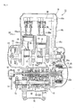
Fig. 1
A left side view of a motorcycle according to an embodiment of the present invention. -
Fig. 2
A left side view of an engine of the motorcycle. -
Fig. 3
A planar cross-sectional view taken along a crank axis and the like of the engine. -
Fig. 4
A left side view with a part in cross section of a transmission and the like arranged on a rear portion of the engine. -
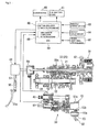
Fig. 5
A schematic constitutional view of a shift control device of the motorcycle. -
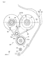
Fig. 6
A left side view of an essential part of the engine. -
Fig. 7
A top plan view with a part in cross section of the constitution of an essential part of the engine. -
Fig. 8
A front view with a part in cross section of the constitution of an essential part of the engine. -
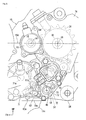
Fig. 9
A left side view of the constitution of essential part of the engine. -
Fig. 10
Fig. 10(a) is a left side view showing the constitution corresponding to the constitution inFig. 9 in a shift-up manipulation, andFig. 10(b) is a left side view showing the constitution corresponding to the constitution inFig. 9 in a shift-down manipulation. -
Fig. 11
An exploded perspective view of a transmission mechanism which constitutes the essential part. -
Fig. 12
Fig. 12(a) is a left side view of a front drum stopper which constitutes the essential part, andFig. 12(b) is a left side view of a rear drum stopper which constitutes the essential part. -
Fig. 13
A planar cross-sectional view taken along a swing axis of the respective drum stoppers. -
Fig. 14
A left side view of driving part of a gear position sensor and a shift spindle angle sensor which constitute the essential part. -
Fig. 15
A left side view of a shifter-side locking mechanism which constitutes the essential part. -
Fig. 16
A left side view of a drum-side locking mechanism which constitutes the essential part. -
Fig. 17
Fig. 17(a) to Fig. 17(d) are explanatory views showing an operation of the shifter-side locking mechanism in order ofFig. 17(a) to Fig. 17(d) . -
Fig. 18
Fig. 18(a) to Fig. 18(d) are explanatory views showing an operation of the - Hereinafter, an embodiment of the present invention is explained in conjunction with drawings. In the explanation made hereinafter, directions of front and rear, left and right are equal to the directions of a vehicle unless otherwise specified. Further, in the drawings, an arrow FR indicates a frontward direction as viewed from the vehicle, an arrow LH indicates a leftward direction as viewed from the vehicle, and an arrow UP indicates an upward direction as viewed from the vehicle respectively.
- In a motorcycle 1 shown in
Fig. 1 , a front wheel 2 of the motorcycle 1 is rotatably and pivotally supported on lower end portions of a pair of left and right front forks 3, and upper portions of the respective front forks 3 are pivotally supported on a head pipe 6 arranged on a front end of a vehicle body frame 5 by way of a steering stem 4 in a steerable manner. Upper end portions of the left and right front forks 3 project from the steering stem 4 in the upward direction, and left and right handle bars 7 are mounted on the projecting portions. - In the vehicle-body frame 5, left and right
main tubes 8 extend obliquely in the downward and rearward direction behind the head pipe 6, and upper end portions of left and right pivot frames 9 are respectively connected to rear end portions of the left and rightmain tubes 8. A front end portion of aswing arm 11 is pivotally and swingably supported on the left and right pivot frames 9, and arear wheel 12 is rotatably and pivotally supported on a rear end portion of theswing arm 11. Anengine 13 is suspended from an inner side of the vehicle body frame 5, and theengine 13 and therear wheel 12 are interconnected with each other such that power can be transmitted by way of a chain-type power transmission mechanism, for example. - To explain the embodiment also in conjunction with
Fig. 2 , theengine 13 is a water-cooled 4-stroke V-type 4-cylinder engine in which a center axis of rotation of a crankshaft 14 (crank axis) C1 extends in the lateral direction (vehicle widthwise direction), for example. Afront cylinder 16 which is raised in the oblique frontward and upward direction and arear cylinder 17 which is raised in the oblique rearward and upward direction are formed on a front upper portion of acrankcase 15 of theengine 13. Here, axes which respectively extend in the raised directions of the front and rear cylinders (front and rear banks) 16, 17 (cylinder axis) are indicated by symbols C2, C3 in the drawing respectively. - The front and
rear cylinders cylinder body cylinder head head cover crankcase 15 side. Here, therespective cylinder bodies crankcase 15. A cylinder bore 18 which corresponds to each cylinder is formed in the inside of therespective cylinder bodies piston 19 is fitted in each cylinder bore 18 in a reciprocating manner. Eachpiston 19 is connected to a crank pin of thecrankshaft 14 by way of a connectingrod 19a so that the reciprocating movement of therespective pistons 19 is converted into the rotational movement of thecrankshaft 14. - The
engine 13 is fixedly supported on the vehicle body frame 5 in such a manner that afront support portion 21 which constitutes a front end of thecrankcase 15 of theengine 13 is fixed to a lower end portion of anengine hanger 8a which extends downwardly from a front portion of themain tube 8 by fastening, and anupper support portion 22 which constitutes an upper portion (a rear portion of the front cylinder 16) of thecrankcase 15 is fixed to a rear side of a proximal end portion of theengine hanger 8a by fastening, and a rearupper support portion 23 and a rearlower support portion 24 which constitute a rear end of thecrankcase 15 are respectively fixed to upper and lower sides of a front portion of thepivot frame 9 by fastening. - The
engine 13 is configured such that a transmission (seeFig. 3 ) 25 is integrally mounted on a rear portion of theengine 13, and a rear portion of thecrankcase 15 also functions as a transmission case. Thecrankcase 15 is, for example, divided into upper andlower case bodies horizontal dividing plane 15d which is arranged parallel to the crank axis C1 as a boundary. Anoil pan 15c is mounted on a lower portion of the crankcase 15 (lower case body 15b). Here, a substantially horizontal plane (a split face between theoil pan 15c and the crankcase 15) formed on a lower end of the crankcase 15 (lower case body 15b) is indicated bysymbol 15e in the drawing. - To explain the embodiment also in conjunction with
Fig. 2 andFig. 3 , an intake-side camshaft 26 and an exhaust-side camshaft 27 are arranged in the inside of therespective cylinder heads camshafts crankshaft 14 by way of a gear-type or chain-typecam drive mechanism 28. Due to the rotational driving of therespective cam shafts exhaust valves respective cylinder heads - Behind the
crankshaft 14, amain shaft 31 and acounter shaft 32 of thetransmission 25 are arranged parallel to each other in the longitudinal direction. Therespective shafts respective shafts plane 15d. - The rotational power of the
crankshaft 14 is outputted to adrive sprocket wheel 36 which is arranged on a left side of a rear portion of thecrankcase 15 by way of a clutch 35 which is arranged in the inside of a right side of thecrankcase 15 and thetransmission 25 which is arranged in the inside of a rear portion of thecrankcase 15, and the rotational power is transmitted to therear wheel 12 from thedrive sprocket wheel 36 by way of adrive chain 36a and the like. - Two
exhaust pipes 37 which correspond to the respective cylinders are connected to a front side of thecylinder heads 16b of thefront cylinders 16, and twoexhaust pipes 37 which correspond to the respective cylinders are connected to a rear side of thecylinder heads 17b of therear cylinders 17 respectively in the same manner. Further, twothrottle bodies 38 which correspond to the respective cylinders are connected to a rear side of thecylinder heads 16b of thefront cylinders 16, and two throttlebodies 38 which correspond to the respective cylinders are connected to a front side of thecylinder heads 17b of therear cylinders 17 respectively in the same manner. In the drawing, numeral 75 indicates a thermostat which is arranged between the front andrear cylinders crankcase 15 and supports a front end portion of theswing arm 11 together with thepivot frame 9. - To explain the embodiment in conjunction with
Fig. 3 , aprimary drive gear 41 is coaxially mounted on a right side portion of thecrankshaft 14 in an integrally rotatable manner, and theprimary drive gear 41 is meshed with a primary drivengear 42 which is coaxially arranged on a right side portion of themain shaft 31. Agenerator 43 is coaxially arranged on a left end portion of thecrankshaft 14. - The clutch 35 which a rider can manipulate is coaxially arranged on a right end portion of the
main shaft 31. The clutch 35 is a well-known wet-type multiple disc clutch. The clutch 35 includes: a clutch outer 35a which has a bottomed cylindrical shape opened rightwardly and is supported on themain shaft 31 in a rotatable manner relative to themain shaft 31, a clutch inner 35b which is supported on themain shaft 31 inside the clutch outer 35a in a non-rotatable manner relative to themain shaft 31, and a plurality ofclutch plates 35c which are arranged between the clutch inner 35b and the clutch outer 35a in a stacked manner and allow or inhibit the power transmission between the clutch inner 35b and the clutch outer 35a. The primary drivengear 42 is mounted on a left side portion of the clutch outer 35a in an integrally rotatable manner. In the drawing,numerals crankcase 15 respectively. - The
transmission 25 is mainly constituted of themain shaft 31 and thecounter shaft 32 which are arranged parallel to thecrankshaft 14, and a group of shift gears 33 which extends between and is supported on bothshafts crankshaft 14 is transmitted to thecounter shaft 32 from themain shaft 31 by way of an arbitrary gear pair of the group of shift gears 33. Thedrive sprocket wheel 36 is mounted on the left end portion of thecounter shaft 32 which projects toward a left side of the rear portion of thecrankcase 15 in an integrally rotatable manner. - The group of shift gears 33 includes gears supported on both
shafts transmission 25 is a constant-mesh transmission in which corresponding gears which form each pair in the group of shift gears 33 are always meshed with each other between bothshafts shafts - To explain this embodiment also in conjunction with
Fig. 2 ,Fig. 4 andFig. 5 , a change mechanism which changes over a shift gear pair of thetransmission 25 is arranged below thetransmission 25. In thechange mechanism 34, due to the rotation of a hollowcylindrical shift drum 51 arranged parallel to bothshafts shift forks 52 are operated corresponding to a pattern of alead groove 51 a formed on an outer periphery of theshift drum 51 so that, among the group of shift gears 33, a gear pair used for the power transmission between bothshafts shift fork shaft 53 which is parallel to theshift drum 51 is arranged obliquely in front of and above theshift drum 51, and ashift spindle 46 which is parallel to theshift drum 51 is arranged below theshift drum 51. In the drawings, symbols C6, C7 indicate a rotational center axis (axis) of theshift spindle 46 and a rotational center axis (axis) of theshift drum 51 along the lateral direction. - Each
shift fork 52 forms afork pin 52b which is engaged with thelead groove 51a of theshift drum 51 on abase portion 52a thereof in which theshift fork shaft 53 is inserted, wherein thefork pin 52b projects obliquely in the rearward and downward direction. When theshift spindle 46 and ashift arm 54 which is fixed to theshift spindle 46 are rotated, theshift drum 51 is rotated by way of a power transmission mechanism (manipulation power transmission means) 81 and the like described later so that theshift fork 52 is moved in the axial direction of theshift fork shaft 53 corresponding to the pattern of thelead groove 51a whereby the predetermined slide gear of the group of shift gears 33 is slid thus changing over a shift position. - The shift spindle 46 projects to the outside of the
crankcase 15 for manipulating thechange mechanism 34, and ashift pedal 47 is connected to a projecting portion of theshift spindle 46 which projects to the outside (left side) of thecrankcase 15 directly or by way of a predetermined link mechanism or the like. Theshift pedal 47 is arranged in the vertically swingable manner such that a front side of theshift pedal 47 constitutes a swing proximal-end side and a rear side of theshift pedal 47 constitutes a swing distal-end side (a manipulation end side operated by a foot of a rider). - Here, the motorcycle 1 provides, besides traveling in a usual manual mode where a rider performs both a manipulation of the clutch 35 and a manipulation of the
transmission 25, traveling in a semiautomatic mode where a rider performs only a shift manipulation (a manipulation of the shift pedal 47) of thetransmission 25, and an engagement/disengagement manipulation of the clutch 35 is automatically performed under an electric control in response to a manipulation of theshift pedal 47. - To explain this embodiment in conjunction with
Fig. 5 , the motorcycle 1 includes amaster cylinder 55 which is mounted on a left handle lever 7, for example, and generates a liquid pressure due to a manipulation of aclutch lever 55a, aslave cylinder 56 which is mounted on a left side of a rear portion of thecrankcase 15 and is operated by receiving the liquid pressure from themaster cylinder 55, and aliquid pressure pipe 57 which extends between therespective cylinders - The
slave cylinder 56 is coaxially arranged with themain shaft 31, and is operated when a liquid pressure is supplied to theslave cylinder 56 from themaster cylinder 55. When theslave cylinder 56 is operated, the clutch 35 is operated by way of apush rod 56a which penetrates the inside of themain shaft 31 so that the clutch 35 is brought into a disengagement state from an engagement state. On the other hand, when the supply of the liquid pressure to theslave cylinder 56 is stopped, theslave cylinder 56 is returned to a state before the above-mentioned operation and, at the same time, the clutch 35 is returned to an engagement state due to an action of a clutch spring thereof. - An
actuator 58 which automatically performs the disengagement of the clutch 35 in a semiautomatic mode is arranged on an intermediate portion of theliquid pressure pipe 57. Theactuator 58 includes a drive source such as an electric motor not shown in the drawing, and a liquid pressure control for engaging or disengaging the clutch 35 is performed by controlling an operation of theactuator 58 using anECU 59. - To the
ECU 59, detection information from agear position sensor 61 which detects a shift position based on a rotation angle of theshift drum 51, detection information from a shiftspindle angle sensor 62 which detects a rotation angle of theshift spindle 46, and various vehicle state detection information from athrottle opening sensor 63, avehicle speed sensor 64, an enginerotational speed sensor 65 and the like are inputted. Based on the respective information, an operation control of theactuator 58 and an operation control of anignition device 66 and afuel injection device 67 are performed. - Further, the
ECU 59 includes a shift manipulation start detection means 68 which detects starting of a shift manipulation by a rider, and a shift change completion detection means 69 which detects the completion of the shift operation by the shift manipulation. Accordingly, in the semiautomatic mode, theECU 59 performs the operation control of theactuator 58 and hence, the engagement and the disengagement of the clutch 35 are performed automatically in response to the shift manipulation. - To explain this embodiment in conjunction with
Fig. 6 andFig. 7 , awater pump 71 having an approximately circular shape as viewed in a side view and including adrive shaft 71a which extends in the lateral direction is arranged on a left lower rear side of thecrankcase 15. On the left lower rear side of thecrankcase 15 and behind thewater pump 71, amechanism housing chamber 72 which opens leftwardly (outwardly) is provided. On a left opening of themechanism housing chamber 72, a leftrear cover 73 which closes the left opening is mounted. On a front outer side of themechanism housing chamber 72 and the leftrear cover 73, thewater pump 71 is arranged such that a rear portion of thewater pump 71 overlaps with themechanism housing chamber 72 and the leftrear cover 73 as viewed in a side view. - A
drive sprocket wheel 36 and a drivesprocket wheel cover 74 which covers an outer side of thedrive sprocket wheel 36 are arranged above themechanism housing chamber 72. In the inside of a lower portion of the drivesprocket wheel cover 74, themechanism housing chamber 72 and the leftrear cover 73 are arranged such that an upper portions of themechanism housing chamber 72 and the leftrear cover 73 overlap with each other as viewed in a side view. In the inside of a lower end portion of thedrive sprocket wheel 36, an upper end portion of themechanism housing chamber 72 and an upper end portion of the leftrear cover 73 are arranged so as to overlap with each other as viewed in a side view. - The
slave cylinder 56 is mounted on an outer side of a front end portion of the drivesprocket wheel cover 74, and thegear position sensor 61 is mounted on an outer side of a lower end portion of the drivesprocket wheel cover 74. Thevehicle speed sensor 64 which detects a vehicle speed based on a rotational speed of thedrive sprocket wheel 36 is mounted on an outer side of a front portion of an upper end of the drivesprocket wheel cover 74. - A
coupler 61a into which a harness-side connector not shown in the drawing can be inserted is formed on a lower side of a front portion of thegear position sensor 61 in a state where thecoupler 61a projects obliquely in the frontward and downward direction. Thecoupler 61a is arranged outside a rear end portion of thewater pump 71 such that thecoupler 61a overlaps with thewater pump 71 as viewed in a side view. - A shift
spindle angle sensor 62 which detects a rotation angle of theshift spindle 46 is mounted on an outer side of a front lower portion of the leftrear cover 73. Acoupler 62a into which a harness-side connector not shown in the drawing can be inserted is formed on a lower side of a front portion of the shiftspindle angle sensor 62 in a state where thecoupler 62a projects obliquely in the frontward and downward direction. Thewater pump 71 is arranged outside the shiftspindle angle sensor 62 such that a rear lower portion of thewater pump 71 overlaps with the shiftspindle angle sensor 62 as viewed in a side view. - To explain this embodiment in conjunction with
Fig. 8 andFig. 9 , to a laterally intermediate portion of theshift spindle 46 which faces the inside of the crankcase 15 (the inside of the mechanism housing chamber 72), a proximal end portion of a plate-shapedshift arm 54 which approximately orthogonally intersects with theshift spindle 46 is fixed. Theshift arm 54 extends toward the outside of theshift drum 51 arranged above theshift spindle 46, and theshift arm 54 and theshift drum 51 are engaged with each other by way of thepower transmission mechanism 81. A manipulationpower transmission mechanism 81A which transmits a shift manipulation force inputted to theshift spindle 46 to theshift drum 51 is mainly constituted of theshift arm 54, thepower transmission mechanism 81 and apawl ratchet mechanism 91A described later. - To explain this embodiment also in conjunction with
Fig. 12 , thepower transmission mechanism 81 includes an annular shifter-side rotary member 87 and a drum-side rotary member 88 which are coaxial with theshift drum 51, and a lostmotion mechanism 89 which is arranged between the respectiverotary members - Hereinafter, the
pawl ratchet mechanism 91A and the periphery of thepawl ratchet mechanism 91A are explained. - The shifter-
side rotary member 87 has a cup shape which opens leftwardly, and a shifter assembledbody 91 is arranged to be inserted into the inside of the shifter-side rotary member 87. Thepawl ratchet mechanism 91A which converts one reciprocating rotational movement of theshift spindle 46 and theshift arm 54 into the rotational movement about the axis C7 over a predetermined angle is constituted of the shifter-side rotary member 87 and the shifter assembledbody 91. - An engaging
pin 92 is formed on a left side surface of the shifter assembledbody 91 at a position offset from the axis C7 in a state where the engagingpin 92 projects leftwardly. A distal end portion of theshift arm 54 is positioned on a left side of the shifter assembledbody 91, and the engagingpin 92 is engaged with the inside of a recessedportion 93 formed on the distal end portion of theshift arm 54 by way of acollar member 92a. A rotational force of theshift spindle 46 and theshift arm 54 is inputted to the shifter assembledbody 91 by way of the recessedportion 93 and the engagingpin 92. - A
guide hole 94 having a relatively-elongated arcuate shape around the axis C6 is formed on a distal end side of theshift arm 54, and anintermediate guide hole 95 having a relatively short arcuate shape around the axis C6 is formed on a front side of an intermediate portion of theshift arm 54. An intermediate portion of a transmissionmechanism support shaft 96 which is coaxial with theshift drum 51 is inserted into theguide hole 94, and a distal end portion of aguide pin 97 which is mounted upright on an inner side of the leftrear cover 73 is inserted into theintermediate guide hole 95. - In a state where the
shift arm 54 is at a rotation initial position at which the extending direction of theshift arm 54 is aligned with the vertical direction (seeFig. 9 ), the transmissionmechanism support shaft 96 is positioned at a longitudinally center portion of theguide hole 94, and theguide pin 97 is positioned at a longitudinally center portion of theintermediate guide hole 95. Rotation angles of theshift arm 54 at the time of rotating theshift arm 54 from the rotation initial position in the forward direction and in the backward direction respectively (seeFig. 10(a), Fig. 10(b) ) are restricted as theguide pin 97 is brought into contact with inner peripheries of both ends of theintermediate guide hole 95. In the drawings, arrows F, B respectively indicate the forward rotational direction (shift-up direction) and the backward rotational direction (shift-down direction) of theshift drum 51, thepower transmission mechanism 81 and the like around the axis C7. - An engaging
lug 98 which is raised toward leftwardly (outwardly) is formed on theshift arm 54 above theintermediate guide hole 95, and coil ends of areturn spring 99 which is arranged adjacent to a left side (outer side) of a proximal end of theshift arm 54 are engaged with both sides of the engaginglug 98. Thereturn spring 99 is a torsion coil spring in which theshift spindle 46 is inserted, and theguide pin 97 and the engaginglug 98 are clamped between both coil ends. - When the
shift arm 54 is rotated either in the forward direction or in the backward direction from the rotation initial position, the engaginglug 98 and theguide pin 97 make the relative movement around the axis C6 so that both ends of thereturn spring 99 are spaced apart from each other thus generating a biasing force which acts to return theshift arm 54 toward the rotation initial position. - To explain this embodiment in conjunction with
Fig. 9 ,Fig. 10 ,Fig. 12 andFig. 13 , a shifter-side stopper portion 102 which is engaged with afront stopper arm 101 supported on thecrankcase 15 is integrally formed on an outer periphery of the shifter-side rotary member 87. A plurality of shifter-side outer peripheral recessedportions 102a which are arranged at intervals of a predetermined angle are formed on the shifter-side stopper portion 102. By engaging thefront stopper arm 101 with any one of these shifter-side outer peripheral recessedportions 102a, the rotation of the shifter-side rotary member 87 is restricted at intervals of a predetermined angle. Hereinafter, the combination of the shifter-side stopper portion 102 and thefront stopper arm 101 is referred to as afront drum stopper 102A. - With respect to the
front stopper arm 101, a front end portion of anarm body 101a is swingably supported on asupport shaft 101b which is fixedly mounted on thecrankcase 15, and a rear end portion of thearm body 101a is biased toward the shifter-side rotary member 87 which is positioned below thearm body 101a by means of atorsion coil spring 101c in which thesupport shaft 101b is inserted, and astopper roller 101d which is supported on an outer side of the rear end portion is engaged with a shifter-side outer peripheral recessedportion 102a. Accordingly, a predetermined rotation restricting force is applied to the shifter-side rotary member 87 at the predetermined rotational position, and the shifter-side rotary member 87 can be rotated with a rotational force which exceeds such a rotation restricting force. - To explain this embodiment in conjunction with
Fig. 9 ,Fig. 10 , the shifter assembledbody 91 includes ashifter body 105 which is rotatable relative to the shifter-side rotary member 87, a pair ofratchet pawls 106 which are assembled to theshifter body 105, and a pair ofplungers 107 which individually bias therespective ratchet pawls 106 to a shifter outer peripheral side. - To explain this embodiment also in conjunction with
Fig. 8 , a right side portion of theshifter body 105 is housed in the inside of the shifter-side rotary member 87 and a left side portion of theshifter body 105 which is spaced apart from the right side portion in the leftward direction projects toward a left side of the shifter-side rotary member 87. An intermediate portion of the power transmissionmechanism support shaft 96 is inserted into a center portion of theshifter body 105 so that theshifter body 105 and the shifter-side rotary member 87 are connected to each other in a relatively rotatable manner. The engagingpin 92 is mounted on a left side surface of theshifter body 105 in a projecting manner. - The
shifter body 105 is configured in line symmetry with respect to a straight line (shifter center line) T2 which connects an axis of the engagingpin 92 and an axis of the shifter body 105 (an axis of the power transmission mechanism support shaft 96) as viewed in a side view. Hereinafter, a position where the shifter center line T2 in the shifter body 105 (shifter assembled body 91) is aligned with the vertical direction is assumed as a shifter rotation initial position. - On both sides of the
shifter body 105 which sandwich the shifter center line T2 therebetween, therespective ratchet pawls 106 are swingably held so as to move lower portions thereof toward the inside and the outside of theshifter body 105 about upper portions thereof. Therespective ratchet pawls 106 are biased by therespective plungers 107 such that the lower portions of theratchet pawls 106 project toward an outer periphery of theshifter body 105. - On the other hand, a plurality of inner peripheral recessed
portions 108 are formed in the inside of the shifter-side rotary member 87 at intervals of a predetermined angle, and the lower portion of eachratchet pawl 106 is engageable with any one of the respective inner peripheral recessedportions 108 in a contacting manner. In a state where the lower portion of theratchet pawl 106 is engaged with the inner peripheral recessedportions 108 of the shifter-side rotary member 87, the relative rotation between the shifter-side rotary member 87 and the shifter assembledbody 91 toward a side where the lower portion of eachratchet pawl 106 and the inner peripheral recessedportion 108 come into contact with each other is restricted, while the relative rotation between the shifter-side rotary member 87 and the shifter assembledbody 91 toward a side opposite to the side where the lower portion of eachratchet pawl 106 and the inner peripheral recessedportion 108 come into contact with each other is allowed since theratchet pawls 106 enter the inside of theshifter body 105. - To explain this embodiment also in conjunction with
Fig. 12 , between theshift arm 54 and the shifter-side rotary member 87, aguide plate 109 which has a planar shape orthogonal to the lateral direction and allows the shifter assembledbody 91 to pass therethrough is arranged. Aninsertion hole 111 for the shifter assembledbody 91 is formed in a center portion of theguide plate 109, and a plurality ofstay portions 109a are formed on an outer peripheral side of theguide plate 109 for fastening theguide plate 109 to thecrankcase 15. - The
insertion hole 111 has abase diameter portion 111a having the substantially same diameter as a right side portion of theshifter body 105, a pair of enlarged-diameter portions 111b formed on both sides of a lower portion of thebase diameter portion 111a, and aconvex portion 111c formed between the respective enlarged-diameter portions 111b. With respect to the shifter assembledbody 91 which is inserted into theinsertion hole 111, lower portions of theratchet pawls 106 which are positioned in the inside of the respective enlarged-diameter portions 111b are made to project toward the outside of theshifter body 105 so as to be engaged with the inner peripheral recessedportion 108 of the shifter-side rotary member 87. With respect to theratchet pawls 106 positioned in the inside of thebase diameter portion 111a, the lower portions of theratchet pawls 106 get over an inner periphery of thebase diameter portion 111a so that the lower portions enter the inside of theshifter body 105 thus preventing the lower portions of theratchet pawls 106 from being engaged with the inner peripheral recessedportion 108 of the shifter-side rotary member 87. - The
pawl ratchet mechanism 91A, when the shifter assembledbody 91 is in the shifter rotation initial position (seeFig. 9 ), positions therespective ratchet pawls 106 within the respective enlarged-diameter portions 111b such that theratchet pawls 106 are engageable with any one of the respective inner peripheral recessedportions 108 of the shifter-side rotary member 87. By engaging eachratchet pawl 106 with any one of the inner peripheral recessedportions 108, the relative rotation between the shifter assembledbody 91 and the shifter-side rotary member 87 in both forward and backward directions is not allowed. - On the other hand, when the shifter assembled
body 91 is rotated in one direction from the shifter rotation initial position together with the shifter-side rotary member 87 due to the rotation of the shift arm 54 (seeFig. 10 ), theratchet pawl 106 on a side where the shifter assembledbody 91 is rotated in the other direction gets over an inner periphery of thebase diameter portion 111a of theguide plate 109 and enters theshifter body 105 so that the engagement of theratchet pawl 106 with the inner peripheral recessedportion 108 is not allowed. Accordingly, the relative rotation of the shifter assembledbody 91 in the other direction relative to the shifter-side rotary member 87 is allowed. - That is, after the shifter assembled
body 91 and the shifter-side rotary member 87 are rotated in one direction, only the shifter assembledbody 91 is allowed to be rotated (idling being allowed) in the other direction with respect to the shifter-side rotary member 87 whose rotation is restricted by thedrum stopper 102A due to a cooperative operation with theguide plate 109. Here, the forward and backward rotations of the shifter assembledbody 91 from the shifter rotation initial position are restricted within a predetermined angle since theguide pin 97 is brought into contact with the inner peripheries of both ends of theintermediate guide hole 95 formed in theshift arm 54. Further, the excessive rotation of the shifter-side rotary member 87 generated by inertia is restricted since the a lower portion of either one of theratchet pawls 106 is brought into contact with a side end of theconvex portion 111c of theguide plate 109. - Due to such reciprocating rotational movement of the shifter assembled
body 91 in the forward and backward directions, the shifter-side rotary member 87 can be fed intermittently in the forward and backward rotational directions respectively. The rotation of the shifter-side rotary member 87 is transmitted to the drum-side rotary member 88 by way of the lostmotion mechanism 89 so that theshift drum 51 is rotated together with the drum-side rotary member 88 by a predetermined angle whereby a shift position of thetransmission 25 is changed one stage by one stage. That is, an angle that theshift drum 51 is rotated at a time due to intermittent feeding corresponds to an angle that the shift position of thetransmission 25 is shifted up or shifted down by one stage. - The lost
motion mechanism 89 and the periphery of the lostmotion mechanism 89 are explained hereinafter. - To explain the lost
motion mechanism 89 in conjunction withFig. 8 andFig. 10 , the drum-side rotary member 88 has a cup shape which is opened leftwardly. A bottom portion of the drum-side rotary member 88 is fixed to a left end portion of theshift drum 51 by fastening, and a right end portion of the power transmissionmechanism support shaft 96 which is coaxial with theshift drum 51 is inserted into the inside of the drum-side rotary member 88. A left end portion of theshift drum 51, the drum-side rotary member 88 and a right end portion of the power transmissionmechanism support shaft 96 are engaged with each other in an integrally rotatable manner by way of aknock pin 88b which extends in the lateral direction. The drum-side rotary member 88 does not have the constitution corresponding to the inner peripheral recessedportions 108. - On an outer periphery of the drum-
side rotary member 88, a drum-side stopper portion 104 with which arear stopper arm 103 supported on thecrankcase 15 is engaged is integrally formed. On the drum-side stopper portion 104, a plurality of drum-side outer peripheral recessedportions 104a which are arranged at intervals of a predetermined angle are formed. By engaging therear stopper arm 103 with any one of the drum-side outer peripheral recessedportions 104a, the rotation of the drum-side rotary member 88 is restricted for every predetermined angle. Hereinafter, the combination of the drum-side stopper portion 104 and therear stopper arm 103 is referred to as arear drum stopper 104A. - To explain the lost
motion mechanism 89 also in conjunction withFig. 13 , a rear end portion of anarm body 103a of therear stopper arm 103 is swingably supported on asupport shaft 103b which is fixedly mounted on thecrankcase 15, a front end portion of thearm body 103a is biased toward the drum-side rotary member 88 positioned below thearm body 103a by atorsion coil spring 103c which penetrates thesupport shaft 103b, and astopper roller 103d which is supported on an inner side of a rear end portion of thearm body 103a is engaged with the drum-side outer peripheral recessedportions 104a. Due to such a constitution, a rotation restricting force is applied to the drum-side rotary member 88 at a predetermined rotational position, and the drum-side rotary member 88 becomes rotatable with a rotational force which exceeds the rotation restricting force. - To explain the lost
motion mechanism 89 in conjunction withFig. 8 andFig. 11 , a lostmotion spring 114 is held between the shifter-side guide member 112 and the drum-side guide member 113, the rotation of the shifter-side rotary member 87 is transmitted to the drum-side rotary member 88 by way of a resilient force of the lostmotion spring 114, and when theshift spindle 46 is rotated in a state where the rotation of the drum-side rotary member 88 is restricted by alocking mechanism 82 described later, the rotational force can be accumulated in the lostmotion spring 114. - To explain the lost
motion mechanism 89 in conjunction withFig. 7 ,Fig. 15 andFig. 16 , the locking mechanism (manipulation force transmission switching means) 82 is provided for controlling timing of power transmission by thepower transmission mechanism 81, and is mainly constituted of a pair of left andright solenoids shift spindle 46 in the inside of the crankcase 15 (in the inside of the mechanism housing chamber 72) and a pair of left andright arms shift spindle 46. The respective constitutions are described in detail later. - In a state where the rotational force is accumulated in the lost
motion spring 114, when theECU 59 determines that a rotation amount of theshift spindle 46 exceeds a predetermined amount by which a shift drum rotation amount necessary for changing a shift gear position can be ensured based on a detected signal from the shiftspindle angle sensor 62, thelocking mechanism 82 is operated so as to allow the rotation of the drum-side rotary member 88 and hence, the drum-side rotary member 88 and theshift drum 51 are rotated due to the accumulated rotational force whereby the shift position of thetransmission 25 is changed. - To explain the lost
motion mechanism 89 in conjunction withFig. 8 andFig. 11 , the shifter-side guide member 112 includes a cylindricalouter sleeve 112a through which the power transmissionmechanism support shaft 96 penetrates, a curved-plate-shaped shifter-side guide wall 112b which is raised upright toward an inner side (toward ashift drum 51 side) from a portion of theouter sleeve 112a within a predetermined range in the circumferential direction, and a cylindricalinner sleeve 112c which is arranged on an inner peripheral side of theouter sleeve 112a in a spaced-apart manner from the shifter-side guide wall 112b. - In the same manner, the drum-
side guide member 113 includes a cylindricalouter sleeve 113a through which the power transmissionmechanism support shaft 96 penetrates, a curved-plate-shaped drum-side guide wall 113b which is raised upright toward an outer side (toward ashift arm 54 side) from a portion of theouter sleeve 113a within a predetermined range in the circumferential direction, and a cylindricalinner sleeve 113c which is arranged on an inner peripheral side of theouter sleeve 113a in a spaced-apart manner from the drum-side guide wall 113b. - One
coil end 114a of the lostmotion spring 114 which is a torsion coil spring is engaged with a forward-rotational-direction downstream end of the shifter-side guide wall 112b, and theother coil end 114b of the lostmotion spring 114 is engaged with a backward-rotational-direction downstream end of the drum-side guide wall 113b. - The lost
motion spring 114 is held between therespective guide members respective guide walls inner sleeves respective guide members motion spring 114, and the lostmotion spring 114 is covered with therespective guide walls motion spring 114, the shifter-side guide member 112 is biased in the backward rotational direction, and the drum-side rotary member 88 is biased in the forward rotational direction. - In assembling the lost
motion spring 114 between therespective guide members motion spring 114 is performed while twisting the lostmotion spring 114, therespective guide walls motion spring 114 by covering the outer peripheral side of the lostmotion spring 114 within a predetermined range and hence, the assembling operation can be easily performed. - On a raised-direction distal end portion of the shifter-
side guide wall 112b, a shifter-side guidedistal end portion 112d which projects inwardly (toward theshift drum 51 side) in a triangle shape as viewed in the radial direction is provided in a state where the shifter-side guidedistal end portion 112d extends a backward-rotational-direction downstream end thereof. In the same manner, on a raised-direction distal end portion of the drum-side guide wall 113b, a drum-side guidedistal end portion 113d which projects outwardly (toward theshift arm 54 side) in a triangle shape as viewed in the radial direction is formed in a state where the drum-side guidedistal end portion 113d extends a forward-rotational-direction downstream end thereof. - A shifter-
side guide pin 87a which is raised upright inwardly from the shifter-side rotary member 87 is engaged with the backward-rotational-direction downstream end of a raised-direction proximal end portion of the shifter-side guide wall 112b, and a drum-side guide pin 88a which is raised upright outwardly from the drum-side rotary member 88 is engaged with the forward-rotational-direction downstream end of a raised-direction proximal end portion of the drum-side guide wall 113b. A shifter-side guide pin 87a is sandwiched between the backward-rotational-direction downstream end on the proximal end side of the shifter-side guide wall 112b and the forward-rotational-direction downstream end of the drum-side guidedistal end portion 113d, and the drum-side guide pin 88a is sandwiched between the forward-rotational-direction downstream end on the proximal end side of the drum-side guide wall 113b and the backward-rotational-direction downstream end of the shifter-side guidedistal end portion 112d. - Due to such a constitution, during the forward rotation of the shifter-
side rotary member 87, a rotational force is transmitted to the drum-side rotary member 88 by way of the shifter-side guide pin 87a, the shifter-side guide member 112, the lostmotion spring 114, the drum-side guide member 113 and the drum-side guide pin 88a in this order. During the backward rotation of the shifter-side rotary member 87, a rotational force is transmitted to the drum-side rotary member 88 by way of the shifter-side guide pin 87a, the drum-side guide member 113, the lostmotion spring 114, the shifter-side guide member 112 and the drum-side guide pin 88a in this order. - On the other hand, in the state where the rotation of the drum-
side rotary member 88 is restricted by thelocking mechanism 82, when the shifter-side rotary member 87 is rotated in the forward direction, only the shifter-side guide member 112 is rotated so that only a force necessary for rotating the drum-side guide member 113 and the drum-side rotary member 88 in the forward direction is accumulated in the lostmotion spring 114. When the shifter-side rotary member 87 is rotated in the backward direction, only the drum-side guide member 113 is rotated so that only a force necessary for rotating the shifter-side guide member 112 and the drum-side rotary member 88 in the backward direction is accumulated in the lostmotion spring 114. - By releasing the rotation restriction of the drum-
side rotary member 88 which is made by thelocking mechanism 82 at predetermined timing from such a state, it is possible to perform a shift change by rotating the drum-side rotary member 88 and theshift drum 51. - The
locking mechanism 82 is explained in detail hereinafter. - To explain the
locking mechanism 82 in conjunction withFig. 7 ,Fig. 15 andFig. 16 , a left-side solenoid out ofrespective solenoids respective arms 85, 86 (hereinafter referred to as the shifter-side solenoid 83 and the shifter-side arm 85 respectively, and the combination of these parts being referred to as a shifter-side locking mechanism 82a) allow the rotation of the shifter-side rotary member 87 until a rotation amount of theshift spindle 46 reaches the above-mentioned predetermined amount, and restricts the rotation of the shifter-side rotary member 87 when the rotation amount of theshift spindle 46 becomes the above-mentioned predetermined amount. - Further, a right-side solenoid out of
respective solenoids respective arms 85, 86 (hereinafter referred to as the drum-side solenoid 84 and the drum-side arm 86 respectively, and the combination of these parts being referred to as a drum-side locking mechanism 82b) restrict the rotation of the drum-side rotary member 88 in a state where the rotation of the shifter-side rotary member 87 is allowed (until the rotation amount of theshift spindle 46 reaches the predetermined amount), and allows the rotation of the drum-side rotary member 88 when the rotation of the shifter-side rotary member 87 is restricted (when the rotation amount of theshift spindle 46 reaches the predetermined amount). - These locking
mechanisms rotary members rotary members - The
respective solenoids respective solenoids respective solenoids single solenoid case 116 having a laterally elongated elliptical shape as viewed from above. A fixingscrew shaft 116a for thecrankcase 15 is formed on a right end portion of thesolenoid case 116 in a projecting manner. On a left end portion of thesolenoid case 116, a pair of front and rear engagingpins 116b corresponding to a lower side of a front portion of theguide plate 109 is formed in a projecting manner and, at the same time, a support shaft 116c of therotary member 62c which constitutes a part of the shiftspindle angle sensor 62 is mounted in a projecting manner. - In each
solenoid plunger coil plunger plunger distal end portion arm - Rear end portions (
proximal portions respective arms pivot shaft 117 which is fixed to thecrankcase 15 and extends in the lateral direction in a state where the rear end portions are inserted into thepivot shaft 117. Therespective arms arms pivot shaft 117. Thepivot shaft 117 is positioned below rear end portions of the respectiverotary members respective solenoids rotary members Torsion coil springs pivot shaft 117 is inserted are arranged on rear end portions of therespective arms respective springs respective plungers 83b, 84e, therespective arms respective arms torsion coil springs - The shifter-
side arm 85 includes the cylindricalproximal portion 85a into which thepivot shaft 117 is inserted, thearm body 85b which extends frontwardly from a lateral inner side of theproximal portion 85a, and adistal end portion 85c which is raised toward a lateral outer side from a front end portion of thearm body 85b. Anengaging pin 85d which is engaged with a shifter-side engaging portion 118 of the shifter-side rotary member 87 positioned above thearm body 85b is mounted on a longitudinally-intermediate portion of thearm body 85b in a projecting manner. - The engaging
pin 85d is only resiliently engaged with a shifter-side engaging recessedportion 118a of the shifter-side engaging portion 118 when the shifter-side solenoid 83 is not energized, and when a predetermined or more rotational force acts, the engagingpin 85d gets over a side end of the shifter-side engaging recessedportion 118a and allows the rotation of the shifter-side rotary member 87. On the other hand, when the shifter-side solenoid 83 is energized so that theplunger 83b is fixedly held in an elevated state, the engagingpin 85d does not get over the side end of the shifter-side engaging recessedportion 118a so that the rotation of the shifter-side rotary member 87 is locked. - In the same manner, the drum-
side arm 86 includes the cylindricalproximal portion 86a into which thepivot shaft 117 is inserted, thearm body 86b which extends frontwardly from a lateral outer side of theproximal portion 86a, and adistal end portion 86c which is raised toward a lateral inner side from a front end portion of thearm body 86b. Anengaging pin 86d which is engaged with a drum engaging portion of the drum-side rotary member 88 positioned above thearm body 86b is mounted on a longitudinally-intermediate portion of thearm body 86b in a projecting manner. - The engaging
pin 86d is only resiliently engaged with a drum-side engaging recessedportion 119a of the drum-side engaging portion 119 when the drum-side solenoid 84 is not energized, and when a predetermined rotational force or more acts, the engagingpin 86d gets over a side end of the drum-side engaging recessedportion 119a and allows the rotation of the drum-side rotary member 88. On the other hand, when the drum-side solenoid 84 is energized so that theplunger 84b is fixedly held in an elevated state, the engagingpin 86d does not get over the side end of the drum-side engaging recessedportion 119a so that the rotation of the drum-side rotary member 88 is locked. - On a portion of an outer periphery of the shifter-
side rotary member 87 which is positioned on a more lateral inner side (lostmotion mechanism 89 side) than the shifter-side stopper portion 102, the shifter-side engaging portion 118 with which theengaging pin 85d of the shifter-side arm 85 is engaged is integrally formed. A plurality of shifter-side engaging recessedportions 118a which are arranged at intervals of a predetermined angle are formed on the shifter-side engaging portion 118. By engaging the engagingpin 85d of the shifter-side arm 85 with any one of the shifter-side engaging recessedportion 118a, the rotation of the shifter-side rotary member 87 is restricted for every predetermined angle. In the drawing, symbol indicates retainers which are arranged along wall portions of the portions which are provided for guiding lines extending from therespective solenoids mechanism housing chamber 72. - In the same manner, on a portion of an outer periphery of the drum-
side rotary member 88 which is positioned on a more lateral outer side (lostmotion mechanism 89 side) than the drum-side stopper portion 104, the drum-side engaging portion 119 with which theengaging pin 86d of the drum-side arm 86 is engaged is integrally formed. A plurality of drum-side engaging recessedportion 119a which are arranged at intervals of a predetermined angle are formed on the drum-side engaging portion 119. By engaging the engagingpin 86d of the drum-side arm 86 of the drum-side locking mechanism 82b with any one of the drum-side engaging recessedportions 119a, the rotation of the drum-side rotary member 88 is restricted for every predetermined angle. - The shifter-side engaging recessed
portion 118a is engaged with the engagingpin 85d with a larger play in the circumferential direction than the drum-side engaging recessedportion 119a. Further, in each engaging recessedportion side end side end - Here, the
respective solenoids respective arms shift drum 51 and theshift spindle 46 arranged vertically as viewed in a side view, and are arranged above asplit face 15e between thecrankcase 15 and theoil pan 15c. Therespective arms shift spindle 46 and theshift drum 51 as viewed in a side view. - Further, the center of rotation (axis C8, fulcrum) of rear ends of the
respective arms distal end portions respective arms respective solenoids pins respective arms rotary members Fig. 15 ,symbol 116d indicates a retainer which guides lines extending from therespective solenoids mechanism housing chamber 72, andsymbol 116e indicates a grommet mounted on a leading hole for pulling out the above-mentioned lines. - Hereinafter, the shift
spindle angle sensor 62 and thegear position sensor 61 will be described. - To explain the shift
spindle angle sensor 62 and thegear position sensor 61 in conjunction withFig. 6 ,Fig. 7 andFig. 14 , theshift spindle sensor 62 is arranged outwardly from therespective solenoids rear cover 73. The shiftspindle angle sensor 62 detects a rotation angle of theshift spindle 46 based on a rotation amount of arotary shaft 62b which is held in the inside of the housing and extends in the lateral direction. A distal end portion of arotary member 62c which penetrates the leftrear cover 73 from the inside of the leftrear cover 73 is engaged with an inner end of therotary shaft 62b in an integrally rotatable manner. Therotary member 62c is supported on a support shaft 116c which is mounted on an outer end of thesolenoid case 116 in a projecting manner and extends in the lateral direction in a state where therotary member 62c is rotatable about an axis of the support shaft 116c. - A plate-shaped
portion 62d which has an elliptical shape as viewed in a side view and extends rearwardly is integrally formed on an inner end of therotary member 62c. Anengaging pin 54a which is raised upright toward the inside in the lateral direction from a front side of a proximal end of theshift arm 54 is engaged with the inside of anotch 62e which is formed on a rear portion of the plate-shapedportion 62d and is opened rearward. Due to such a constitution, when theshift arm 54 is rotated together with theshift spindle 46, therotary shaft 62b of the shiftspindle angle sensor 62 is rotated by way of therotary member 62c, and a rotation angle of theshift spindle 46 can be detected based on a rotation amount of therotary shaft 62b. - Further, the
gear position sensor 61 detects a rotation angle of the shift drum 51 (power transmission mechanism support shaft 96) based on a rotation amount of a rotor not shown in the drawing which is held in the inside of a housing of thegear position sensor 61. A pair of engagingpins 61b which project outwardly from therotary member 61c held by thedrive sprocket cover 74 is engaged with an inner portion of the rotor. Therotary member 61c is supported by a holdinghole 61d which is formed in thedrive sprocket cover 74 and extends in the lateral direction in a rotatable manner about an axis thereof. - A
sector gear 61e which extends obliquely in the frontward and downward direction in a fan shape as viewed in a side view is integrally mounted on an outer end of therotary member 61c. Apinion gear 96a which is formed on an outer end of the power transmissionmechanism support shaft 96 is meshed with gear teeth formed on a distal end of thesector gear 61e. Due to such a constitution, when the power transmissionmechanism support shaft 96 is rotated together with theshift drum 51, the rotor of thegear position sensor 61 is rotated by way of therotary member 61c and hence, a rotation angle of theshift drum 51 and, eventually, a shift position of thetransmission 25 can be detected based on a rotation amount. - Next, the manner of operation of this embodiment is explained.
- Firstly, in a state where a shift manipulation of the
transmission 25 is not performed so that the respective engagingpins respective arms portions Fig. 15 andFig. 16 ), the shifter-side solenoid 83 is in a non-energized state, and the drum-side solenoid 84 is in an energized state (or bothsolenoids - For example, when the
shift pedal 47 is manipulated toward a shift-up side from such a state so that theshift spindle 46 and theshift arm 54 are rotated toward a shift-up side, the shifter-side rotary member 87 starts to rotate in the forward direction by way of thepawl ratchet mechanism 91A (seeFig. 10 ). - Since the shifter-
side solenoid 83 is in a non-energized state and the drum-side solenoid 84 is in an energized state, the engagingpin 85d of the shifter-side arm 85 gets over the side end of the shifter-side engaging recessedportion 118a with a predetermined rotational force so that the rotation of the shifter-side rotary member 87 is allowed, while theplunger 84b is fixedly held in an elevated state so that the rotation of the drum-side rotary member 88 is locked (seeFig. 17(a) andFig. 18(a) ). Due to the relative rotation between the respectiverotary members shift drum 51 is accumulated in the lostmotion mechanism 89. - The rotation of the
shift spindle 46 is detected by theECU 59 by way of the shiftspindle angle sensor 62. When theECU 59 determines that the rotational angle of theshift spindle 46 reaches the above-mentioned predetermined value, in other words, when theECU 59 determines that a force which can ensure a rotation amount of theshift drum 51 which is necessary for changing the shift gear position is accumulated in the lostmotion mechanism 89, theECU 59 switches energy states of therespective solenoids side solenoid 83 is brought into an energized state, and the drum-side solenoid 84 is brought into a non-energized state (seeFig. 17(b) andFig. 18(b) ). - Then, the
plunger 83b is fixedly held in an elevated state so that the rotation of the shifter-side rotary member 87 is locked, while the engagingpin 86d of the drum-side arm 86 gets over the side end of the drum-side engaging recessedportion 119a with a predetermined rotational force so that the rotation of the drum-side rotary member 88 is allowed (seeFig. 17(c) andFig. 18(c) ). Here, the drum-side rotary member 88 and theshift drum 51 are rotated by making use of a rotational force accumulated in the lostmotion mechanism 89. - The rotation of the
shift drum 51 is detected by theECU 59 by way of thegear position sensor 61. When theECU 59 determines that the shift change is completed, theECU 59 switches the energy states of therespective solenoids respective solenoids side solenoid 83 is in a non-energized state and the drum-side solenoid 84 is in an energized state (seeFig. 17(d) andFig. 18(d) ). - In this manner, by accumulating the force which is necessary for changing over the shift gear position in the lost
motion mechanism 89 and, thereafter, by rotating theshift drum 51 by releasing the accumulated force, the reliability of a shift change and feeling of shift manipulation in a semiautomatic mode can be enhanced. - Further, the shift control device also possesses additional functions including a function which prevents an unintended operation of the
change mechanism 34 due to an inadvertent external force (caused by a manipulation of a rider such as touching theshift pedal 47 unconsciously, for example). - As has been explained heretofore, with respect to the shift control device of the saddle-ride-type vehicle of this embodiment, in the shift control device which includes the
engine 13 and thetransmission 25 and is applied to the motorcycle 1, thetransmission 25 includes theshift spindle 46 which is rotated due to the external force for shifting, and theshift drum 51 which is intermittently rotated corresponding to the rotation of theshift spindle 46 so as to operate theshift fork 52 thereby performing the selection of the shift gear, the shift control device includes the lostmotion mechanism 89 which is arranged between theshift spindle 46 and theshift drum 51 and engages the shifter-side rotary member 87 on theshift spindle 46 side and the drum-side rotary member 88 on theshift drum 51 side with each other in the relatively rotatable manner while accumulating a force, and thelocking mechanism 82 which is engaged with the shifter-side rotary member 87 and the drum-side rotary member 88 respectively so as to restrict the rotation of the shifter-side rotary member 87 and the rotation of the drum-side rotary member 88 individually. - Due to such a constitution, by restricting the rotation of one of the respective
rotary members rotary members locking mechanism 82, a shift manipulation force is accumulated by causing the relative rotation between the respectiverotary members shift drum 51 is rotated by releasing this force at predetermined timing and hence, shift start timing can be surely controlled and, at the same time, it is possible to surely make an accumulated force act until the completion of shifting. - In the shift control device of the saddle-ride-type vehicle, the
locking mechanism 82 includes: the shifter-side solenoid 83 which allows the rotation of the shifter-side rotary member 87 until the rotation amount of theshift spindle 46 reaches the predetermined amount by which a rotation amount of theshift drum 51 necessary for changing a shift gear position of thetransmission 25 can be ensured, and restricts the rotation of the shifter-side rotary member 87 when the rotation amount of theshift spindle 46 becomes the predetermined amount; and the drum-side solenoid 84 which restricts the rotation of the drum-side rotary member 88 in the state where the rotation of the shifter-side rotary member 87 is allowed, and allows the rotation of the drum-side rotary member 88 when the rotation of the shifter-side rotary member 87 is restricted. - Due to such a constitution, it is possible to allow the lost
motion mechanism 89 to accumulate a shift manipulation force with the simple structure that the rotations of the respectiverotary members respective solenoids side rotary member 87 so that the drum-side rotary member 88 and theshift drum 51 can be rotated whereby the reliability of a shift change and feeling of shift manipulation can be enhanced. - In the shift control device of the saddle-ride-type vehicle, the respective
rotary members motion mechanism 89 includes: the shifter-side guide member 112 which is engaged with the respectiverotary members rotary members side guide member 113 which is engaged with the respectiverotary members rotary members motion spring 114 which is held between therespective guide members side guide member 112 in the backward rotational direction, and biases the drum-side guide member 113 in the forward rotational direction. - Due to such a constitution, a rotational force is transmitted to the drum-
side rotary member 88 in order of the shifter-side guide member 112, the lostmotion spring 114 and the drum-side guide member 113 during the forward rotation of the shifter-side rotary member 87, while the rotational force is transmitted to the drum-side rotary member 88 in order of the drum-side guide member 113, the lostmotion spring 114 and the shifter-side guide member 112 during the backward rotation of the shifter-side rotary member 87. Here, when the rotation of the drum-side rotary member 88 is restricted, during the forward rotation of the shifter-side rotary member 87, only the shifter-side guide member 112 is rotated so that a force which rotates the drum-side guide member 113 and the drum-side rotary member 88 in the forward direction is accumulated in the lostmotion spring 114, while during the backward rotation of the shifter-side rotary member 87, only the drum-side guide member 113 is rotated so that a force which rotates the shifter-side guide member 112 and the drum-side rotary member 88 in the backward direction is accumulated in the lostmotion spring 114. Then, by releasing the rotation restriction of the drum-side rotary member 88 at predetermined timing, the drum-side rotary member 88 and theshift drum 51 are rotated so that a shift change can be performed. In this manner, it is possible to realize the accumulation means which accumulates a rotational force of theshift drum 51 with the simple constitution. - In the shift control device of the saddle-ride-type vehicle, the
shift spindle 46 and theshift drum 51 are arranged in the lateral direction, and therespective solenoids shift spindle 46 and theshift drum 51 as viewed in the side view. - Due to such a constitution, by arranging the
respective solenoids shift spindle 46 and theshift drum 51, it is possible to provide a compact engine layout by which it is unnecessary to additionally ensure spaces for arranging therespective solenoids - In the shift control device of the saddle-ride-type vehicle, the
respective solenoids solenoid case 116, and the support shaft 116c of the shiftspindle angle sensor 62 is mounted on thesolenoid case 116 in the projecting manner. - Due to such a constitution, it is possible to constitute the shift
spindle angle sensor 62 using the small number of parts. - The present invention is not limited to the above-mentioned embodiment, and is also applicable to a vehicle having the constitution in which an engine (crankcase) and a transmission (transmission case) are formed as separate bodies, for example.
- Further, it is needless to say that the constitution of the embodiment is merely one example of the present invention, and various modifications can be made without departing from the gist of the present invention.
- The present invention is directed to enhance reliability of a shift change and feeling of a shift manipulation with the simple and compact layout constitution in a shift control device of a saddle-ride-type vehicle in which, while the engagement and disengagement of a clutch is automatically performed by an actuator, a shift manipulation of a transmission is performed by a rider's manipulation.
- The shift control device includes a lost
motion mechanism 89 which is arranged between ashift spindle 46 and ashift drum 51 and engages a shifter-side rotary member 87 on ashift spindle 46 side and a drum-side rotary member 88 on ashift drum 51 side with each other in a relatively rotatable manner while accumulating a force, and a locking mechanism which is engaged with the shifter-side rotary member 87 and the drum-side rotary member 88 respectively so as to restrict the rotation of the shifter-side rotary member 87 and the rotation of the drum-side rotary member 88 individually.
Claims (5)
- A shift control device of a saddle-ride-type vehicle (1) which comprises an engine (13) and a transmission (25), wherein the transmission (25) includes a shift spindle (46) which is rotated due to an external force for shifting and a shift drum (51) which is intermittently rotated corresponding to the rotation of the shift spindle (46) so as to operate a shift fork (52) thereby performing the selection of a shift gear,
the improvement being characterized in that the shift control device comprises a lost motion mechanism (89) which is arranged between the shift spindle (46) and the shift drum (51) and engages an upstream-side rotary member (87) on a shift spindle (46) side and a downstream-side rotary member (88) on a shift drum (51) side with each other in a relatively rotatable manner while accumulating a force, and a locking mechanism (82) which is engaged with the upstream-side rotary member (87) and the downstream-side rotary member (88) respectively so as to restrict the rotation of the upstream-side rotary member (87) and the rotation of the downstream-side rotary member (88) individually. - The shift control device of a saddle-ride-type vehicle according to claim 1, wherein the locking mechanism (82) comprises:an upstream-side solenoid (83) which allows the rotation of the upstream-side rotary member (87) until a rotation amount of the shift spindle (46) reaches a predetermined amount by which a rotation amount of the shift drum (51) necessary for changing a shift gear position of the transmission (25) can be ensured and restricts the rotation of the upstream-side rotary member (87) when the rotation amount of the shift spindle (46) becomes the predetermined amount; anda downstream-side solenoid (84) which restricts the rotation of the downstream-side rotary member (88) in a state where the rotation of the upstream-side rotary member (87) is allowed, and allows the rotation of the downstream-side rotary member (88) when the rotation of the upstream-side rotary member (87) is restricted.
- The shift control device of a saddle-ride-type vehicle according to claim 1 or 2, wherein
the respective rotary members (87, 88) are arranged coaxially with each other, and
the lost motion mechanism (89) comprises: a first guide member (112) which is engaged with the respective rotary members (87, 88) in an integrally rotatable manner when the respective rotary members (87, 88) are rotated in a forward direction; a second guide member (113) which is engaged with the respective rotary members (87, 88) in an integrally rotatable manner when the respective rotary members (87, 88) are rotated in a backward direction; and a lost motion spring (114) which is held between the respective guide members (112, 113), biases the first guide member (112) in the backward rotational direction, and biases the second guide member (113) in the forward rotational direction. - The shift control device of a saddle-ride-type vehicle according to claim 2, wherein the shift spindle (46) and the shift drum (51) are arranged in the lateral direction, and
the respective solenoids (83, 84) are arranged in front of a straight line (T1) which connects respective axes (C6, C7) of the shift spindle (46) and the shift drum (51) as viewed in a side view. - The shift control device of a saddle-ride-type vehicle according to claim 2 or 4, wherein the respective solenoids (83, 84) are housed in one case (116), and a pivot portion (116c) of a shift spindle angle sensor (62) is mounted on the case (116) in a projecting manner.
Applications Claiming Priority (1)
| Application Number | Priority Date | Filing Date | Title |
|---|---|---|---|
| JP2010062669A JP5373678B2 (en) | 2010-03-18 | 2010-03-18 | Shift control device for saddle riding type vehicle |
Publications (2)
| Publication Number | Publication Date |
|---|---|
| EP2366918A1 true EP2366918A1 (en) | 2011-09-21 |
| EP2366918B1 EP2366918B1 (en) | 2012-06-06 |
Family
ID=43640152
Family Applications (1)
| Application Number | Title | Priority Date | Filing Date |
|---|---|---|---|
| EP11151114A Active EP2366918B1 (en) | 2010-03-18 | 2011-01-17 | Shift control device of saddle-ride-type vehicle |
Country Status (4)
| Country | Link |
|---|---|
| US (1) | US8555739B2 (en) |
| EP (1) | EP2366918B1 (en) |
| JP (1) | JP5373678B2 (en) |
| ES (1) | ES2386620T3 (en) |
Cited By (1)
| Publication number | Priority date | Publication date | Assignee | Title |
|---|---|---|---|---|
| US20220135181A1 (en) * | 2019-03-04 | 2022-05-05 | Honda Motor Co., Ltd. | Saddle-riding type vehicle |
Families Citing this family (20)
| Publication number | Priority date | Publication date | Assignee | Title |
|---|---|---|---|---|
| JP5331514B2 (en) * | 2009-02-26 | 2013-10-30 | 本田技研工業株式会社 | Shift control device for saddle riding type vehicle |
| US8607719B1 (en) * | 2009-05-01 | 2013-12-17 | George Kuzni | Feed regulator for thermostatic control |
| JP5911782B2 (en) * | 2012-09-28 | 2016-04-27 | 本田技研工業株式会社 | Gearbox type transmission |
| JP6191078B2 (en) * | 2013-03-28 | 2017-09-06 | 本田技研工業株式会社 | Power unit for motorcycle |
| JP6164890B2 (en) | 2013-03-29 | 2017-07-19 | 本田技研工業株式会社 | Power unit for saddle-ride type vehicles |
| DE102013205829A1 (en) * | 2013-04-03 | 2014-10-09 | Bayerische Motoren Werke Aktiengesellschaft | Routing device for vehicles |
| DE102014101189B4 (en) | 2014-01-31 | 2019-07-25 | Hs Products Engineering Gmbh | Power transmission device for a transmission and assembly method |
| JP6244240B2 (en) * | 2014-03-26 | 2017-12-06 | 本田技研工業株式会社 | Saddle riding vehicle |
| JP5940580B2 (en) * | 2014-03-28 | 2016-06-29 | 本田技研工業株式会社 | Power transmission device for vehicle |
| IN2014MU02140A (en) * | 2014-07-02 | 2015-04-24 | Star Engineers I Pvt Ltd | |
| JP5996701B1 (en) * | 2015-03-30 | 2016-09-21 | 本田技研工業株式会社 | Transmission with synchro mechanism |
| JP6641810B2 (en) | 2015-09-08 | 2020-02-05 | スズキ株式会社 | Transmission system for vehicles |
| DE102016201860A1 (en) * | 2016-02-08 | 2017-08-10 | Bayerische Motoren Werke Aktiengesellschaft | Device and method for locking a shift drum of a sequential gearbox |
| US10626929B2 (en) | 2016-05-09 | 2020-04-21 | Team Industries, Inc. | Dual clutch |
| JP6736442B2 (en) * | 2016-09-29 | 2020-08-05 | 本田技研工業株式会社 | Gear change operation detector |
| KR102406125B1 (en) * | 2017-11-14 | 2022-06-07 | 현대자동차 주식회사 | Oblique motor |
| IT201800009928A1 (en) * | 2018-10-30 | 2020-04-30 | Piaggio & C Spa | TRANSMISSION UNIT FOR MOTOR VEHICLES WITH REVERSE GEAR AND MOTOR VEHICLE INCLUDING THE TRANSMISSION UNIT |
| JP7071314B2 (en) * | 2019-07-12 | 2022-05-18 | 本田技研工業株式会社 | Transmission of saddle-riding vehicle |
| JP2024033393A (en) * | 2022-08-30 | 2024-03-13 | スズキ株式会社 | shift device |
| US20260063202A1 (en) * | 2024-08-29 | 2026-03-05 | New Kailung Gear Co., Ltd. | Camshaft assembly for gear switching apparatus of vehicle |
Citations (4)
| Publication number | Priority date | Publication date | Assignee | Title |
|---|---|---|---|---|
| US5395293A (en) * | 1992-06-02 | 1995-03-07 | Honda Giken Kogyo Kabushiki Kaisha | Speed change controller for vehicle |
| JP2009209970A (en) | 2008-02-29 | 2009-09-17 | Honda Motor Co Ltd | Shift control device of transmission |
| EP2159458A1 (en) * | 2008-08-29 | 2010-03-03 | Honda Motor Co., Ltd | Transmission of vehicle |
| US20100242655A1 (en) * | 2009-03-31 | 2010-09-30 | Yoshihisa Ieda | Gear shift device |
Family Cites Families (14)
| Publication number | Priority date | Publication date | Assignee | Title |
|---|---|---|---|---|
| JPS5225343A (en) * | 1975-08-15 | 1977-02-25 | Honda Motor Co Ltd | Speed shifting position controller for motor cycle |
| JPS58170953A (en) * | 1982-04-01 | 1983-10-07 | Honda Motor Co Ltd | Drum type switching device for transmission |
| JP2539601B2 (en) * | 1985-07-22 | 1996-10-02 | ヤマハ発動機株式会社 | Transmission for vehicle |
| JP4530237B2 (en) * | 2000-03-29 | 2010-08-25 | 本田技研工業株式会社 | Transmission |
| JP2002267013A (en) * | 2001-03-13 | 2002-09-18 | Denso Corp | Shift switching device |
| US6880420B2 (en) * | 2003-08-22 | 2005-04-19 | Yen-Hsing Shen | Automatic control device for a motorized vehicle gearbox |
| JP4501405B2 (en) * | 2003-10-22 | 2010-07-14 | スズキ株式会社 | Vehicle transmission |
| JP2005300481A (en) * | 2004-04-15 | 2005-10-27 | Honda Motor Co Ltd | Motorcycle with vehicle speed sensor |
| JP2006090405A (en) * | 2004-09-22 | 2006-04-06 | Honda Motor Co Ltd | Transmission |
| JP4856405B2 (en) * | 2005-07-27 | 2012-01-18 | 川崎重工業株式会社 | Transmission, motorcycle, and vehicle |
| US7454993B2 (en) * | 2006-04-19 | 2008-11-25 | Kawasaki Jikogyo Kabushiki Kaisha | Drive transmission changer for a dog clutch of a vehicle |
| JP4970099B2 (en) * | 2007-03-22 | 2012-07-04 | 本田技研工業株式会社 | Vehicle transmission |
| US7891262B2 (en) * | 2007-09-28 | 2011-02-22 | Honda Motor Co., Ltd. | Transmission for vehicles |
| JP5198204B2 (en) * | 2008-09-30 | 2013-05-15 | 本田技研工業株式会社 | Vehicle reverse device |
-
2010
- 2010-03-18 JP JP2010062669A patent/JP5373678B2/en active Active
-
2011
- 2011-01-17 EP EP11151114A patent/EP2366918B1/en active Active
- 2011-01-17 ES ES11151114T patent/ES2386620T3/en active Active
- 2011-03-15 US US13/048,256 patent/US8555739B2/en active Active
Patent Citations (4)
| Publication number | Priority date | Publication date | Assignee | Title |
|---|---|---|---|---|
| US5395293A (en) * | 1992-06-02 | 1995-03-07 | Honda Giken Kogyo Kabushiki Kaisha | Speed change controller for vehicle |
| JP2009209970A (en) | 2008-02-29 | 2009-09-17 | Honda Motor Co Ltd | Shift control device of transmission |
| EP2159458A1 (en) * | 2008-08-29 | 2010-03-03 | Honda Motor Co., Ltd | Transmission of vehicle |
| US20100242655A1 (en) * | 2009-03-31 | 2010-09-30 | Yoshihisa Ieda | Gear shift device |
Cited By (2)
| Publication number | Priority date | Publication date | Assignee | Title |
|---|---|---|---|---|
| US20220135181A1 (en) * | 2019-03-04 | 2022-05-05 | Honda Motor Co., Ltd. | Saddle-riding type vehicle |
| US11897577B2 (en) * | 2019-03-04 | 2024-02-13 | Honda Motor Co., Ltd. | Saddle-riding type vehicle |
Also Published As
| Publication number | Publication date |
|---|---|
| US20110226080A1 (en) | 2011-09-22 |
| JP2011196433A (en) | 2011-10-06 |
| ES2386620T3 (en) | 2012-08-23 |
| EP2366918B1 (en) | 2012-06-06 |
| JP5373678B2 (en) | 2013-12-18 |
| US8555739B2 (en) | 2013-10-15 |
Similar Documents
| Publication | Publication Date | Title |
|---|---|---|
| EP2366918B1 (en) | Shift control device of saddle-ride-type vehicle | |
| JP4704308B2 (en) | Twin clutch transmission | |
| US9157510B2 (en) | Gearbox of saddle-ridden vehicle | |
| US8371987B2 (en) | Automatic speed change control system for vehicle | |
| US20080128239A1 (en) | Engine including clutch actuator | |
| JP4499083B2 (en) | Engine equipped with variable speed actuator | |
| WO2008038737A1 (en) | Twin clutch device | |
| WO2008038724A1 (en) | Gear shift device | |
| JP5345579B2 (en) | Shift control device for saddle riding type vehicle | |
| JP2008089069A (en) | Gear shift device | |
| WO2008041606A1 (en) | Twin clutch device | |
| JP2002161979A (en) | Transmission for vehicles | |
| JP5438565B2 (en) | Shift control device for saddle riding type vehicle | |
| JP6160063B2 (en) | Gear shift device for transmission | |
| JP5031812B2 (en) | Engine equipped with variable speed actuator | |
| JP5190430B2 (en) | Always open clutch structure | |
| JP2022056600A (en) | Vehicle transmission | |
| JP5715465B2 (en) | Saddle riding | |
| JP5829416B2 (en) | Saddle riding | |
| JP5706711B2 (en) | Vehicle with power unit | |
| EP2857706B1 (en) | Straddle-type vehicle | |
| JP2020193693A (en) | Power transmission device | |
| US8857285B2 (en) | Saddle type vehicle and vehicle power unit | |
| JP2012211630A (en) | Power unit for vehicle | |
| JP6800263B2 (en) | Transmission of saddle-type vehicle |
Legal Events
| Date | Code | Title | Description |
|---|---|---|---|
| PUAI | Public reference made under article 153(3) epc to a published international application that has entered the european phase |
Free format text: ORIGINAL CODE: 0009012 |
|
| 17P | Request for examination filed |
Effective date: 20110117 |
|
| AK | Designated contracting states |
Kind code of ref document: A1 Designated state(s): AL AT BE BG CH CY CZ DE DK EE ES FI FR GB GR HR HU IE IS IT LI LT LU LV MC MK MT NL NO PL PT RO RS SE SI SK SM TR |
|
| AX | Request for extension of the european patent |
Extension state: BA ME |
|
| GRAP | Despatch of communication of intention to grant a patent |
Free format text: ORIGINAL CODE: EPIDOSNIGR1 |
|
| GRAS | Grant fee paid |
Free format text: ORIGINAL CODE: EPIDOSNIGR3 |
|
| GRAA | (expected) grant |
Free format text: ORIGINAL CODE: 0009210 |
|
| RIN1 | Information on inventor provided before grant (corrected) |
Inventor name: TOMODA, AKIHIKO Inventor name: IEDA, YOSHIHISA Inventor name: EMIZU, OSAMU |
|
| AK | Designated contracting states |
Kind code of ref document: B1 Designated state(s): AL AT BE BG CH CY CZ DE DK EE ES FI FR GB GR HR HU IE IS IT LI LT LU LV MC MK MT NL NO PL PT RO RS SE SI SK SM TR |
|
| REG | Reference to a national code |
Ref country code: GB Ref legal event code: FG4D |
|
| REG | Reference to a national code |
Ref country code: CH Ref legal event code: EP Ref country code: AT Ref legal event code: REF Ref document number: 561195 Country of ref document: AT Kind code of ref document: T Effective date: 20120615 |
|
| REG | Reference to a national code |
Ref country code: IE Ref legal event code: FG4D |
|
| REG | Reference to a national code |
Ref country code: DE Ref legal event code: R096 Ref document number: 602011000059 Country of ref document: DE Effective date: 20120802 |
|
| REG | Reference to a national code |
Ref country code: ES Ref legal event code: FG2A Ref document number: 2386620 Country of ref document: ES Kind code of ref document: T3 Effective date: 20120823 |
|
| REG | Reference to a national code |
Ref country code: NL Ref legal event code: VDEP Effective date: 20120606 |
|
| PG25 | Lapsed in a contracting state [announced via postgrant information from national office to epo] |
Ref country code: SE Free format text: LAPSE BECAUSE OF FAILURE TO SUBMIT A TRANSLATION OF THE DESCRIPTION OR TO PAY THE FEE WITHIN THE PRESCRIBED TIME-LIMIT Effective date: 20120606 Ref country code: CY Free format text: LAPSE BECAUSE OF FAILURE TO SUBMIT A TRANSLATION OF THE DESCRIPTION OR TO PAY THE FEE WITHIN THE PRESCRIBED TIME-LIMIT Effective date: 20120606 Ref country code: LT Free format text: LAPSE BECAUSE OF FAILURE TO SUBMIT A TRANSLATION OF THE DESCRIPTION OR TO PAY THE FEE WITHIN THE PRESCRIBED TIME-LIMIT Effective date: 20120606 Ref country code: RS Free format text: LAPSE BECAUSE OF FAILURE TO SUBMIT A TRANSLATION OF THE DESCRIPTION OR TO PAY THE FEE WITHIN THE PRESCRIBED TIME-LIMIT Effective date: 20120606 Ref country code: NO Free format text: LAPSE BECAUSE OF FAILURE TO SUBMIT A TRANSLATION OF THE DESCRIPTION OR TO PAY THE FEE WITHIN THE PRESCRIBED TIME-LIMIT Effective date: 20120906 Ref country code: FI Free format text: LAPSE BECAUSE OF FAILURE TO SUBMIT A TRANSLATION OF THE DESCRIPTION OR TO PAY THE FEE WITHIN THE PRESCRIBED TIME-LIMIT Effective date: 20120606 |
|
| REG | Reference to a national code |
Ref country code: AT Ref legal event code: MK05 Ref document number: 561195 Country of ref document: AT Kind code of ref document: T Effective date: 20120606 |
|
| REG | Reference to a national code |
Ref country code: LT Ref legal event code: MG4D Effective date: 20120606 |
|
| PG25 | Lapsed in a contracting state [announced via postgrant information from national office to epo] |
Ref country code: LV Free format text: LAPSE BECAUSE OF FAILURE TO SUBMIT A TRANSLATION OF THE DESCRIPTION OR TO PAY THE FEE WITHIN THE PRESCRIBED TIME-LIMIT Effective date: 20120606 Ref country code: GR Free format text: LAPSE BECAUSE OF FAILURE TO SUBMIT A TRANSLATION OF THE DESCRIPTION OR TO PAY THE FEE WITHIN THE PRESCRIBED TIME-LIMIT Effective date: 20120907 Ref country code: HR Free format text: LAPSE BECAUSE OF FAILURE TO SUBMIT A TRANSLATION OF THE DESCRIPTION OR TO PAY THE FEE WITHIN THE PRESCRIBED TIME-LIMIT Effective date: 20120606 Ref country code: SI Free format text: LAPSE BECAUSE OF FAILURE TO SUBMIT A TRANSLATION OF THE DESCRIPTION OR TO PAY THE FEE WITHIN THE PRESCRIBED TIME-LIMIT Effective date: 20120606 |
|
| PG25 | Lapsed in a contracting state [announced via postgrant information from national office to epo] |
Ref country code: RO Free format text: LAPSE BECAUSE OF FAILURE TO SUBMIT A TRANSLATION OF THE DESCRIPTION OR TO PAY THE FEE WITHIN THE PRESCRIBED TIME-LIMIT Effective date: 20120606 Ref country code: SK Free format text: LAPSE BECAUSE OF FAILURE TO SUBMIT A TRANSLATION OF THE DESCRIPTION OR TO PAY THE FEE WITHIN THE PRESCRIBED TIME-LIMIT Effective date: 20120606 Ref country code: EE Free format text: LAPSE BECAUSE OF FAILURE TO SUBMIT A TRANSLATION OF THE DESCRIPTION OR TO PAY THE FEE WITHIN THE PRESCRIBED TIME-LIMIT Effective date: 20120606 Ref country code: NL Free format text: LAPSE BECAUSE OF FAILURE TO SUBMIT A TRANSLATION OF THE DESCRIPTION OR TO PAY THE FEE WITHIN THE PRESCRIBED TIME-LIMIT Effective date: 20120606 Ref country code: AT Free format text: LAPSE BECAUSE OF FAILURE TO SUBMIT A TRANSLATION OF THE DESCRIPTION OR TO PAY THE FEE WITHIN THE PRESCRIBED TIME-LIMIT Effective date: 20120606 Ref country code: CZ Free format text: LAPSE BECAUSE OF FAILURE TO SUBMIT A TRANSLATION OF THE DESCRIPTION OR TO PAY THE FEE WITHIN THE PRESCRIBED TIME-LIMIT Effective date: 20120606 Ref country code: IS Free format text: LAPSE BECAUSE OF FAILURE TO SUBMIT A TRANSLATION OF THE DESCRIPTION OR TO PAY THE FEE WITHIN THE PRESCRIBED TIME-LIMIT Effective date: 20121006 Ref country code: BE Free format text: LAPSE BECAUSE OF FAILURE TO SUBMIT A TRANSLATION OF THE DESCRIPTION OR TO PAY THE FEE WITHIN THE PRESCRIBED TIME-LIMIT Effective date: 20120606 |
|
| PG25 | Lapsed in a contracting state [announced via postgrant information from national office to epo] |
Ref country code: PL Free format text: LAPSE BECAUSE OF FAILURE TO SUBMIT A TRANSLATION OF THE DESCRIPTION OR TO PAY THE FEE WITHIN THE PRESCRIBED TIME-LIMIT Effective date: 20120606 Ref country code: PT Free format text: LAPSE BECAUSE OF FAILURE TO SUBMIT A TRANSLATION OF THE DESCRIPTION OR TO PAY THE FEE WITHIN THE PRESCRIBED TIME-LIMIT Effective date: 20121008 |
|
| PLBE | No opposition filed within time limit |
Free format text: ORIGINAL CODE: 0009261 |
|
| STAA | Information on the status of an ep patent application or granted ep patent |
Free format text: STATUS: NO OPPOSITION FILED WITHIN TIME LIMIT |
|
| PG25 | Lapsed in a contracting state [announced via postgrant information from national office to epo] |
Ref country code: DK Free format text: LAPSE BECAUSE OF FAILURE TO SUBMIT A TRANSLATION OF THE DESCRIPTION OR TO PAY THE FEE WITHIN THE PRESCRIBED TIME-LIMIT Effective date: 20120606 |
|
| 26N | No opposition filed |
Effective date: 20130307 |
|
| REG | Reference to a national code |
Ref country code: DE Ref legal event code: R097 Ref document number: 602011000059 Country of ref document: DE Effective date: 20130307 |
|
| PG25 | Lapsed in a contracting state [announced via postgrant information from national office to epo] |
Ref country code: BG Free format text: LAPSE BECAUSE OF FAILURE TO SUBMIT A TRANSLATION OF THE DESCRIPTION OR TO PAY THE FEE WITHIN THE PRESCRIBED TIME-LIMIT Effective date: 20120906 |
|
| PG25 | Lapsed in a contracting state [announced via postgrant information from national office to epo] |
Ref country code: MC Free format text: LAPSE BECAUSE OF NON-PAYMENT OF DUE FEES Effective date: 20130131 |
|
| REG | Reference to a national code |
Ref country code: IE Ref legal event code: MM4A |
|
| REG | Reference to a national code |
Ref country code: FR Ref legal event code: ST Effective date: 20130930 |
|
| PG25 | Lapsed in a contracting state [announced via postgrant information from national office to epo] |
Ref country code: FR Free format text: LAPSE BECAUSE OF NON-PAYMENT OF DUE FEES Effective date: 20130131 |
|
| PG25 | Lapsed in a contracting state [announced via postgrant information from national office to epo] |
Ref country code: IE Free format text: LAPSE BECAUSE OF NON-PAYMENT OF DUE FEES Effective date: 20130117 Ref country code: AL Free format text: LAPSE BECAUSE OF FAILURE TO SUBMIT A TRANSLATION OF THE DESCRIPTION OR TO PAY THE FEE WITHIN THE PRESCRIBED TIME-LIMIT Effective date: 20120606 |
|
| PG25 | Lapsed in a contracting state [announced via postgrant information from national office to epo] |
Ref country code: MT Free format text: LAPSE BECAUSE OF FAILURE TO SUBMIT A TRANSLATION OF THE DESCRIPTION OR TO PAY THE FEE WITHIN THE PRESCRIBED TIME-LIMIT Effective date: 20120606 |
|
| REG | Reference to a national code |
Ref country code: CH Ref legal event code: PL |
|
| PG25 | Lapsed in a contracting state [announced via postgrant information from national office to epo] |
Ref country code: LI Free format text: LAPSE BECAUSE OF NON-PAYMENT OF DUE FEES Effective date: 20140131 Ref country code: CH Free format text: LAPSE BECAUSE OF NON-PAYMENT OF DUE FEES Effective date: 20140131 |
|
| REG | Reference to a national code |
Ref country code: DE Ref legal event code: R084 Ref document number: 602011000059 Country of ref document: DE |
|
| REG | Reference to a national code |
Ref country code: DE Ref legal event code: R084 Ref document number: 602011000059 Country of ref document: DE Effective date: 20141120 |
|
| PG25 | Lapsed in a contracting state [announced via postgrant information from national office to epo] |
Ref country code: SM Free format text: LAPSE BECAUSE OF FAILURE TO SUBMIT A TRANSLATION OF THE DESCRIPTION OR TO PAY THE FEE WITHIN THE PRESCRIBED TIME-LIMIT Effective date: 20120606 |
|
| PG25 | Lapsed in a contracting state [announced via postgrant information from national office to epo] |
Ref country code: TR Free format text: LAPSE BECAUSE OF FAILURE TO SUBMIT A TRANSLATION OF THE DESCRIPTION OR TO PAY THE FEE WITHIN THE PRESCRIBED TIME-LIMIT Effective date: 20120606 |
|
| PG25 | Lapsed in a contracting state [announced via postgrant information from national office to epo] |
Ref country code: LU Free format text: LAPSE BECAUSE OF NON-PAYMENT OF DUE FEES Effective date: 20130117 Ref country code: HU Free format text: LAPSE BECAUSE OF FAILURE TO SUBMIT A TRANSLATION OF THE DESCRIPTION OR TO PAY THE FEE WITHIN THE PRESCRIBED TIME-LIMIT; INVALID AB INITIO Effective date: 20110117 Ref country code: MK Free format text: LAPSE BECAUSE OF FAILURE TO SUBMIT A TRANSLATION OF THE DESCRIPTION OR TO PAY THE FEE WITHIN THE PRESCRIBED TIME-LIMIT Effective date: 20120606 |
|
| GBPC | Gb: european patent ceased through non-payment of renewal fee |
Effective date: 20150117 |
|
| PG25 | Lapsed in a contracting state [announced via postgrant information from national office to epo] |
Ref country code: GB Free format text: LAPSE BECAUSE OF NON-PAYMENT OF DUE FEES Effective date: 20150117 |
|
| PGFP | Annual fee paid to national office [announced via postgrant information from national office to epo] |
Ref country code: ES Payment date: 20180201 Year of fee payment: 8 |
|
| REG | Reference to a national code |
Ref country code: ES Ref legal event code: FD2A Effective date: 20200309 |
|
| PG25 | Lapsed in a contracting state [announced via postgrant information from national office to epo] |
Ref country code: ES Free format text: LAPSE BECAUSE OF NON-PAYMENT OF DUE FEES Effective date: 20190118 |
|
| PGFP | Annual fee paid to national office [announced via postgrant information from national office to epo] |
Ref country code: IT Payment date: 20200114 Year of fee payment: 10 |
|
| PG25 | Lapsed in a contracting state [announced via postgrant information from national office to epo] |
Ref country code: IT Free format text: LAPSE BECAUSE OF NON-PAYMENT OF DUE FEES Effective date: 20210117 |
|
| PGFP | Annual fee paid to national office [announced via postgrant information from national office to epo] |
Ref country code: DE Payment date: 20251217 Year of fee payment: 16 |