EP2365698A2 - 3D eyeglasses, charging cradle, 3D display apparatus and system for charging 3D eyeglasses wirelessly - Google Patents
3D eyeglasses, charging cradle, 3D display apparatus and system for charging 3D eyeglasses wirelessly Download PDFInfo
- Publication number
- EP2365698A2 EP2365698A2 EP11151315A EP11151315A EP2365698A2 EP 2365698 A2 EP2365698 A2 EP 2365698A2 EP 11151315 A EP11151315 A EP 11151315A EP 11151315 A EP11151315 A EP 11151315A EP 2365698 A2 EP2365698 A2 EP 2365698A2
- Authority
- EP
- European Patent Office
- Prior art keywords
- eyeglasses
- pair
- charging
- voltage
- display apparatus
- Prior art date
- Legal status (The legal status is an assumption and is not a legal conclusion. Google has not performed a legal analysis and makes no representation as to the accuracy of the status listed.)
- Withdrawn
Links
Images


Classifications
-
- H—ELECTRICITY
- H04—ELECTRIC COMMUNICATION TECHNIQUE
- H04N—PICTORIAL COMMUNICATION, e.g. TELEVISION
- H04N13/00—Stereoscopic video systems; Multi-view video systems; Details thereof
- H04N13/30—Image reproducers
- H04N13/332—Displays for viewing with the aid of special glasses or head-mounted displays [HMD]
-
- H—ELECTRICITY
- H04—ELECTRIC COMMUNICATION TECHNIQUE
- H04N—PICTORIAL COMMUNICATION, e.g. TELEVISION
- H04N2213/00—Details of stereoscopic systems
- H04N2213/008—Aspects relating to glasses for viewing stereoscopic images
Definitions
- Apparatuses and methods consistent with exemplary embodiments relate to three-dimensional (3D) eyeglasses, a charging cradle, a 3D display apparatus, and a system for charging 3D eyeglasses wirelessly, and more particularly, to 3D eyeglasses, a charging cradle, a 3D display apparatus, and a system for charging 3D eyeglasses wirelessly, which are provided to allow a user to watch a 3D image presented by displaying a left-eye image and a right-eye image alternately.
- 3D stereoscopy is applied to diverse fields such as information communication, broadcasting, medical service, education, training, military, games, animation, virtual reality, computer-aided design (CAD), and industrial technologies, and is the core base technology of next generation 3D stereoscopic multimedia information communication, which is commonly used in the aforementioned diverse fields.
- diverse fields such as information communication, broadcasting, medical service, education, training, military, games, animation, virtual reality, computer-aided design (CAD), and industrial technologies, and is the core base technology of next generation 3D stereoscopic multimedia information communication, which is commonly used in the aforementioned diverse fields.
- the stereoscopic sense that a person generally perceives is generated by the complex action of diverse factors, such as a degree of change in thickness of eye lens according to the location of an object being observed, an angle difference in the angle of the object as observed from both eyes, differences in location and shape of the object as observed from the right and left eyes, a time difference due to a movement of the object, and various other psychological and memory effects.
- diverse factors such as a degree of change in thickness of eye lens according to the location of an object being observed, an angle difference in the angle of the object as observed from both eyes, differences in location and shape of the object as observed from the right and left eyes, a time difference due to a movement of the object, and various other psychological and memory effects.
- Binocular disparity which appears due to the horizontal separation of an approximate 6-7 cm between a person's left and right eyes, is the most important factor in the perception of a stereoscopic sense. That is, a person observes an object at different angles as seen from the left and right eyes due to the binocular disparity and thus the images perceived by the two eyes are different. If these two images are transmitted to the brain through the retinas, the brain accurately combines two pieces of information and thus perceives an 3D stereoscopic image.
- 3D image display apparatuses are divided into glasses-type apparatuses, which use special eyeglasses, and non-glasses-type apparatuses which do not use eyeglasses.
- a glasses-type apparatus may employ a color filter scheme which separates and selects an image using complementary color filters, a polarization filter scheme which separates a left-eye image and a right-eye image using a light shielding effect obtained by a combination of orthogonal polarization elements, or a shutter glasses scheme which alternately shades the left-eye and the right-eye in response to a synchronization signal which projects a left-eye image signal and a right-eye image signal onto a screen, thereby allowing the person to perceive a stereoscopic image.
- users wear 3D eyeglasses. That is, the 3D eyeglasses must be worn in order for a user to perceive a 3D image produced using a glasses-type method.
- the user may insert a disposable battery into the 3D eyeglasses or use a universal serial bus (USB) cable.
- USB universal serial bus
- the battery must be frequently replaced, which increases the cost.
- the USB cable must always be at hand in case the 3D eyeglasses need to be charged, and the USB cable may be considered to be an unsightly or undesirable peripheral.
- Exemplary embodiments overcome the above disadvantages and other disadvantages not described above. However, it is understood that an exemplary embodiment is not required to overcome the disadvantages described above, and an exemplary embodiment may not overcome any of the problems described above.
- Exemplary embodiments provide 3D eyeglasses which are charged wirelessly using an external apparatus, a charging cradle, a 3D display apparatus, and a system for charging 3D eyeglasses wirelessly.
- a pair of 3D eyeglasses which operates in association with a 3D display apparatus, the pair of 3D eyeglasses including: a wireless charging unit which generates electricity using a signal wirelessly received from an external apparatus, and a power supply unit which supplies power to the 3D eyeglasses using the electricity generated by the wireless charging unit.
- the wireless charging unit may generate the electricity using a resonance wave.
- the wireless charging unit may include: a reception resonator which wirelessly receives the resonance wave from the external apparatus , a rectifier which rectifies the received resonance wave to a direct current (DC), a voltage adjuster which adjusts a voltage of the rectified DC such that the voltage is maintained at a constant level, and a charging unit which supplies the voltage to the power supply unit.
- a reception resonator which wirelessly receives the resonance wave from the external apparatus
- a rectifier which rectifies the received resonance wave to a direct current (DC)
- a voltage adjuster which adjusts a voltage of the rectified DC such that the voltage is maintained at a constant level
- a charging unit which supplies the voltage to the power supply unit.
- the external apparatus may be the 3D display apparatus, and the reception resonator may have a resonance frequency equal to a resonance frequency of a transmission resonator included in the 3D display apparatus.
- the reception resonator may be located in a rim of the pair of 3D eyeglasses.
- the reception resonator may be located in a temple of the pair of 3D eyeglasses.
- the external apparatus may be a 3D display apparatus.
- the wireless charging unit may charge the pair 3D eyeglasses wirelessly using a non-contact charging method.
- the wireless charging unit may include: a secondary coil which is magnetically coupled to a primary coil of the external apparatus such that an induced electromotive force is generated, a rectifier which rectifies the induced electromotive force to a DC, a voltage adjuster which adjusts a voltage of the rectified DC such that the voltage is maintained at a constant level, and a charging unit which supplies the voltage to the power supply unit.
- the external apparatus may be a charging cradle that includes the primary coil.
- the charging unit may be a super capacitor.
- a charging cradle for charging a pair of 3D eyeglasses
- the charging cradle including: a power supply unit which supplies power, and a wireless transmitter which wirelessly transmits energy using the supplied power in order to charge the pair of 3D eyeglasses.
- the charging cradle may be mountable to a 3D display apparatus.
- the charging cradle may include a plurality of extensions by which be a plurality of pairs of 3D eyeglasses may be supported.
- the charging cradle may include a plurality of containers within each of which a of pair of 3D eyeglasses may be contained.
- the charging cradle may include a container within which a plurality of pairs of 3D eyeglasses may be contained collectively.
- the charging cradle may include a surface on which a plurality of pairs of 3D eyeglasses may be supported.
- a 3D display apparatus which operates in association with a pair of 3D eyeglasses, the 3D display apparatus including: a power supply unit which supplies power, and a wireless transmitter which wirelessly transmits energy using the supplied power in order to charge the pair of 3D eyeglasses.
- a system for charging a pair of 3D eyeglasses wirelessly including: a 3D display apparatus which includes a transmission resonator which transmits a resonance wave, and a pair of 3D eyeglasses which includes: a reception resonator which receives the transmitted resonance wave, a rectifier which rectifies the received resonance wave to a DC, a voltage adjuster to adjust the rectified DC such that the voltage is maintained at a constant level, and a charging unit which stores the voltage.
- a system for charging a pair of 3D eyeglasses wirelessly including: a charging cradle which includes a primary coil which generates a magnetic field, and a pair of 3D eyeglasses which includes: a secondary coil magnetically coupled to the primary coil, such that an electromotive force is induced therein; a rectifier which rectifies the induced electromotive force to a DC; a voltage adjuster which adjusts a voltage of the rectified DC such that the voltage is maintained at a constant level; and a charging unit which stores the voltage.
- FIG. 1 is a view illustrating a system for charging 3D eyeglasses wirelessly according to an exemplary embodiment
- FIG. 2 is a block diagram illustrating a 3D TV according to an exemplary embodiment
- FIG. 3 is a block diagram illustrating a pair of 3D eyeglasses according to an exemplary embodiment
- FIG. 4 is a circuit diagram illustrating a wireless charging unit for wirelessly charging a pair of 3D eyeglasses using a resonance wave according to an exemplary embodiment
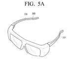
- FIGS. 5A and 5B are views illustrating a location of a reception resonator in the pair of 3D eyeglasses according to an exemplary embodiment
- FIG. 6 is a block diagram illustrating a wireless charging unit of a pair of 3D eyeglasses and a charging cradle using a non-contact charging method according to another exemplary embodiment.
- FIGS. 7A to 7E are views illustrating diverse types of charging cradles according to exemplary embodiments.
- FIG. 1 is a view illustrating a system for charging a pair of 3D eyeglasses 200 wirelessly according to an exemplary embodiment.
- the system includes a 3D television (TV) 100 which wirelessly transmits energy to charge a pair of 3D eyeglasses 200 and the pair of 3D eyeglasses 200 which receive the energy wirelessly.
- TV 3D television
- the 3D TV 100 which is a type of display apparatus, receives a 3D image transmitted from a photographing apparatus such as a camera, or a 3D image transmitted from a broadcasting station after being photographed by a camera and edited/processed by the broadcasting station, processes the received 3D image, and then displays the 3D image on a screen.
- the 3D TV 100 processes a left-eye image and a right-eye image with reference to a format of the 3D image, time-divides the processed left-eye image and the processed right-eye image, and displays them alternately.
- the 3D TV 100 generates a synchronization (sync) signal, which is synchronized with the timing at which the left-eye image and the right-eye image are displayed, and transmits the sync signal to the pair of 3D eyeglasses 200.
- sync synchronization
- the pair of 3D eyeglasses 200 opens and closes a left-eye glass and a right-eye glass alternately according to the sync signal received from the 3D TV 100 so that the user can view the left-eye image and the right-eye image with his/her left-eye and right eye, respectively.
- the pair of 3D eyeglasses 200 If the pair of 3D eyeglasses 200 is located in the vicinity of the 3D TV 100, the pair of 3D eyeglasses 200 also receives a resonance wave which is generated in the 3D TV 100 and which wirelessly charges the 3D eyeglasses 200.
- FIG. 2 is a block diagram illustrating the 3D TV 100 according to an exemplary embodiment.
- the 3D TV 100 includes a function unit 110, a power supply unit 120, a wireless charging transmitter 130, and a controller 140.
- the function unit 110 performs certain general functions of the 3D TV 100. More specifically, the function unit 110 receives 3D broadcast contents from an external source and replays the 3D broadcast contents.
- the power supply unit 120 supplies power to each component of the 3D TV 100 under the control of the controller 140, which will be described below.
- the power supply unit 120 supplies power having a sine wave to the wireless charging transmitter 130 in order to charge the pair of 3D eyeglasses 200 wirelessly.
- the wireless charging transmitter 130 generates a resonance wave for charging the pair of 3D eyeglasses 200 wirelessly using the power supplied from the power supply unit 120.
- the resonance wave described herein refers to an electromagnetic wave having a specific resonance frequency.
- the wireless charging transmitter 130 includes a transmission resonator (not shown).
- the transmission resonator is a resonance circuit that includes an inductor L and a capacitor C and has a specific resonance frequency.
- the transmission resonator is activated by the power supplied from the power supply unit 120 and generates the resonance wave having a specific resonance frequency in order for a reception resonator of the pair of 3D eyeglasses 200 to generate resonance.
- the resonance wave generated by the transmission resonator enables the pair of 3D eyeglasses 200 to be charged wirelessly.
- a wireless charging process in the pair of 3D eyeglasses 200 will be explained in detail below with reference to FIGS. 3 and 4 .
- the controller 140 controls overall operation of the 3D TV 100 according to a user command received from a user manipulator (not shown).
- controller 140 controls the power supply unit 120 and the wireless charging transmitter 130 so that the 3D TV 100 can charge the pair of 3D eyeglasses 200 wirelessly.
- the controller 140 may control a graphic user interface (GUI) to be generated to display a wireless charging status.
- GUI graphic user interface
- FIG. 3 is a block diagram illustrating the pair of 3D eyeglasses 200 according to an exemplary embodiment.
- the pair of 3D eyeglasses 200 includes an infrared (IR) receiver 210, a controller 220, a wireless charging unit 230, a power supply unit 240, a driving unit 250, and a glasses unit 260.
- IR infrared
- the IR receiver 210 receives the sync signal relating to the 3D image from a glasses signal transmission and reception unit (not shown) of the 3D TV 100.
- the glasses signal transmission and reception unit irradiates the sync signal using infrared rays having directivity, and the IR receiver 210 receives the sync signal in the form of the irradiated IR rays.
- the sync signal transmitted from the glasses signal transmission and reception unit to the IR receiver 210 is an IR signal having a frequency of 60 Hz.
- the wireless charging unit 230 charges power of the pair of 3D eyeglasses 200 wirelessly using the resonance wave generated by the wireless charging transmitter 130.
- FIG. 4 is a view schematically illustrating the wireless charging unit 230.
- the wireless charging unit 230 includes a reception resonator 231, a rectifier 233, a voltage adjuster 235, and a charging unit 237.
- the reception resonator 231 receives the resonance wave generated in the transmission resonator of the 3D TV 100.
- the reception resonator 231 is activated because it has the same resonance frequency as the transmission resonator.
- the reception resonator 231 may be located in the temples of the pair of 3D eyeglasses 200 or located in the rims of the glasses unit 260 of the pair of 3D eyeglasses 200, or in another suitable location in the pair of eyeglasses 200.
- the reception resonator 231 reacts to the resonance wave and the received resonance wave is rectified to a direct current (DC) by the rectifier 233.
- the rectifier 233 includes a bridge diode which includes four diodes and a capacitor which serves as a filter, as shown in FIG. 4 .
- the rectifier 233 may use a different circuit that rectifies an alternating current (AC) to a DC. Since the DC voltage rectified by the rectifier 233 is not always maintained at a constant level, the voltage adjuster 235 adjusts a DC signal so that the DC voltage is maintained at a constant level.
- the voltage adjuster 235 may use a DC/DC converter.
- the charging unit 237 stores the rectified constant voltage.
- the charging unit 237 may be a super capacitor or a rechargeable battery.
- the pair of 3D eyeglasses 200 is charged wirelessly using the resonance wave received from the 3D TV 100.
- the power supply unit 240 supplies power to the components of the pair of 3D eyeglasses 200 under the control of the controller 220, which will be described below.
- the power supply unit 240 supplies the components of the pair of 3D eyeglasses 200 with the power charged by the above-described wireless charging method.
- the driving unit 250 generates driving signals based on a control signal received from the controller 220.
- the driving unit 250 since the glasses unit 260 includes a left-eye glass and a right-eye glass, the driving unit 250 generates a left-eye glass driving signal to drive the left-eye glass and a right-eye glass driving signal to drive the right-eye glass, and transmits the left-eye glass driving signal and the right-eye glass driving signal to the left-eye glass and the right-eye glass, respectively.
- the glasses unit 260 includes the left-eye glass and the right-eye glass as described above, and opens and closes shutters of the left-eye glass and the right-eye glass according to the driving signal received from the driving unit 250.
- the controller 220 controls overall operation of the pair of 3D eyeglasses 200.
- the controller 220 generates a control signal based on an output signal received from the IR receiver 210, and transmits the control signal to the driving unit 250 to control the driving unit 250.
- controller 220 controls the power supply unit 240 to supply the components of the pair of 3D eyeglasses 200 with the power wirelessly charged as described above.
- FIG. 6 is a block diagram illustrating the wireless charging unit 230 of the pair of 3D eyeglasses 200 and a charging cradle 300 using a non-contact charging method according to another exemplary embodiment.
- a charging cradle 300 includes a power supply unit 605 and a primary coil 610.
- the power supply unit 605 supplies power in the form of a sine wave to the primary coil 610 so that a current flows in the primary coil 610.
- a magnetic field is formed around the primary coil 610.
- the charging cradle 300 may have diverse shapes as illustrated in FIGS. 7A to 7E . More specifically, as shown in FIG. 7A , the charging cradle 300 may be attached to the 3D TV 100 at a rear surface thereof, or elsewhere. As shown in FIG. 7B , a charging cradle 300-1 may have a plurality of holders on which a plurality of pairs of 3D eyeglasses 200 may be hung. As shown in FIG. 7C , a charging cradle 300-2 may have the shape of a box in which a plurality of pairs of 3D eyeglasses 200 can be housed. As shown in FIG.
- a charging cradle 300-3 may have the shape of a basket or bowl within which a plurality of pairs of 3D eye glasses 200 can be contained. As shown in FIG. 7E , a charging cradle 300-4 may have the shape of a dish on which one or more pairs of 3D eyeglasses 200 can be placed. Additionally, an exemplary charging cradle may have another shape as would be understood by one of skill in the art.
- the wireless charging unit 230 of the pair of 3D eyeglasses 200 to be used in conjunction with the charging cradle 300, includes a secondary coil 620, a rectifier 630, a voltage adjuster 640, and a charging unit 650. If the secondary coil 620 is located in the vicinity of the magnetic field generated around the primary coil 610 of the charging cradle 300, a current flows in the secondary coil 620 due to electromagnetic induction. That is, the primary coil 610 and the secondary coil 620 are magnetically coupled to each other, thereby causing an induced electromotive force to be generated around the secondary coil 620. The electricity generated in such a manner is rectified to a DC by the rectifier 630.
- the rectifier 630 may include four diodes of a bridge diode type and a capacitor serving as a filter, as shown in FIG. 4 . Of course, a different type of rectifying circuit may be used.
- the voltage adjuster 640 adjusts the rectified DC voltage to be maintained at a constant level.
- the charging unit 650 charges the rectified DC voltage.
- the charging unit 650 may be a rechargeable battery, a super capacitor, or other charging unit as would be understood by one of skill in the art.
- a pair of 3D eyeglasses 200 can be charged wirelessly without a cable, thus improving a user's convenience in charging the pair of 3D eyeglasses 200.
- the 3D display apparatus has been described as a 3D TV 100 in the above exemplary embodiments, this is merely an example. Any apparatus that can display the 3D image can be used.
- the 3D display apparatus may be a 3D monitor or a 3D image projector.
- the resonance wave is generated in the 3D TV 100 in the above exemplary embodiments.
- this is merely an example and any apparatus that includes a transmission resonator may be used.
- the apparatus which generates the resonance wave may be a 3D monitor, a 3D image projector, or a charging cradle.
- the charging cradle 300 includes the primary coil 610.
- the primary coil 610 may be a 3D TV, a 3D monitor, or a 3D image projector.
- the pair of 3D eyeglasses 200 can be charged wirelessly without a cable, a user's convenience in charging the pair of 3D eyeglasses 200 is improved.
Landscapes
- Engineering & Computer Science (AREA)
- Multimedia (AREA)
- Signal Processing (AREA)
- Charge And Discharge Circuits For Batteries Or The Like (AREA)
- Testing, Inspecting, Measuring Of Stereoscopic Televisions And Televisions (AREA)
- Secondary Cells (AREA)
Abstract
Description
- This application claims priority from Korean Patent Application No.
10-2010-0021938, filed on March 11, 2010 - Apparatuses and methods consistent with exemplary embodiments relate to three-dimensional (3D) eyeglasses, a charging cradle, a 3D display apparatus, and a system for charging 3D eyeglasses wirelessly, and more particularly, to 3D eyeglasses, a charging cradle, a 3D display apparatus, and a system for charging 3D eyeglasses wirelessly, which are provided to allow a user to watch a 3D image presented by displaying a left-eye image and a right-eye image alternately.
- 3D stereoscopy is applied to diverse fields such as information communication, broadcasting, medical service, education, training, military, games, animation, virtual reality, computer-aided design (CAD), and industrial technologies, and is the core base technology of next generation 3D stereoscopic multimedia information communication, which is commonly used in the aforementioned diverse fields.
- The stereoscopic sense that a person generally perceives is generated by the complex action of diverse factors, such as a degree of change in thickness of eye lens according to the location of an object being observed, an angle difference in the angle of the object as observed from both eyes, differences in location and shape of the object as observed from the right and left eyes, a time difference due to a movement of the object, and various other psychological and memory effects.
- Binocular disparity, which appears due to the horizontal separation of an approximate 6-7 cm between a person's left and right eyes, is the most important factor in the perception of a stereoscopic sense. That is, a person observes an object at different angles as seen from the left and right eyes due to the binocular disparity and thus the images perceived by the two eyes are different. If these two images are transmitted to the brain through the retinas, the brain accurately combines two pieces of information and thus perceives an 3D stereoscopic image.
- 3D image display apparatuses are divided into glasses-type apparatuses, which use special eyeglasses, and non-glasses-type apparatuses which do not use eyeglasses. A glasses-type apparatus may employ a color filter scheme which separates and selects an image using complementary color filters, a polarization filter scheme which separates a left-eye image and a right-eye image using a light shielding effect obtained by a combination of orthogonal polarization elements, or a shutter glasses scheme which alternately shades the left-eye and the right-eye in response to a synchronization signal which projects a left-eye image signal and a right-eye image signal onto a screen, thereby allowing the person to perceive a stereoscopic image.
- In order to watch a 3D image using a glasses-type apparatus, users wear 3D eyeglasses. That is, the 3D eyeglasses must be worn in order for a user to perceive a 3D image produced using a glasses-type method.
- In order to charge such 3D eyeglasses, the user may insert a disposable battery into the 3D eyeglasses or use a universal serial bus (USB) cable. However, if a disposable battery is used, the battery must be frequently replaced, which increases the cost. Also, if the 3D eyeglasses are charged using a USB cable, the USB cable must always be at hand in case the 3D eyeglasses need to be charged, and the USB cable may be considered to be an unsightly or undesirable peripheral.
- Accordingly, there is a need for a method of charging 3D eyeglasses more easily than known heretofore.
- Exemplary embodiments overcome the above disadvantages and other disadvantages not described above. However, it is understood that an exemplary embodiment is not required to overcome the disadvantages described above, and an exemplary embodiment may not overcome any of the problems described above.
- Exemplary embodiments provide 3D eyeglasses which are charged wirelessly using an external apparatus, a charging cradle, a 3D display apparatus, and a system for charging 3D eyeglasses wirelessly.
- According to an aspect of an exemplary embodiment, there is provided a pair of 3D eyeglasses which operates in association with a 3D display apparatus, the pair of 3D eyeglasses including: a wireless charging unit which generates electricity using a signal wirelessly received from an external apparatus, and a power supply unit which supplies power to the 3D eyeglasses using the electricity generated by the wireless charging unit.
- The wireless charging unit may generate the electricity using a resonance wave.
- The wireless charging unit may include: a reception resonator which wirelessly receives the resonance wave from the external apparatus , a rectifier which rectifies the received resonance wave to a direct current (DC), a voltage adjuster which adjusts a voltage of the rectified DC such that the voltage is maintained at a constant level, and a charging unit which supplies the voltage to the power supply unit.
- The external apparatus may be the 3D display apparatus, and the reception resonator may have a resonance frequency equal to a resonance frequency of a transmission resonator included in the 3D display apparatus.
- The reception resonator may be located in a rim of the pair of 3D eyeglasses.
- The reception resonator may be located in a temple of the pair of 3D eyeglasses.
- The external apparatus may be a 3D display apparatus.
- The wireless charging unit may charge the pair 3D eyeglasses wirelessly using a non-contact charging method.
- The wireless charging unit may include: a secondary coil which is magnetically coupled to a primary coil of the external apparatus such that an induced electromotive force is generated, a rectifier which rectifies the induced electromotive force to a DC, a voltage adjuster which adjusts a voltage of the rectified DC such that the voltage is maintained at a constant level, and a charging unit which supplies the voltage to the power supply unit.
- The external apparatus may be a charging cradle that includes the primary coil.
- The charging unit may be a super capacitor.
- According to an aspect of another exemplary embodiment, there is provided a charging cradle for charging a pair of 3D eyeglasses, the charging cradle including: a power supply unit which supplies power, and a wireless transmitter which wirelessly transmits energy using the supplied power in order to charge the pair of 3D eyeglasses.
- The charging cradle may be mountable to a 3D display apparatus.
- The charging cradle may include a plurality of extensions by which be a plurality of pairs of 3D eyeglasses may be supported.
- The charging cradle may include a plurality of containers within each of which a of pair of 3D eyeglasses may be contained.
- The charging cradle may include a container within which a plurality of pairs of 3D eyeglasses may be contained collectively.
- The charging cradle may include a surface on which a plurality of pairs of 3D eyeglasses may be supported.
- According to an aspect of another exemplary embodiment, there is provided a 3D display apparatus which operates in association with a pair of 3D eyeglasses, the 3D display apparatus including: a power supply unit which supplies power, and a wireless transmitter which wirelessly transmits energy using the supplied power in order to charge the pair of 3D eyeglasses.
- According to an aspect of another exemplary embodiment, there is provided a system for charging a pair of 3D eyeglasses wirelessly, the system including: a 3D display apparatus which includes a transmission resonator which transmits a resonance wave, and a pair of 3D eyeglasses which includes: a reception resonator which receives the transmitted resonance wave, a rectifier which rectifies the received resonance wave to a DC, a voltage adjuster to adjust the rectified DC such that the voltage is maintained at a constant level, and a charging unit which stores the voltage.
- According to an aspect of another exemplary embodiment, there is provided a system for charging a pair of 3D eyeglasses wirelessly, the system including: a charging cradle which includes a primary coil which generates a magnetic field, and a pair of 3D eyeglasses which includes: a secondary coil magnetically coupled to the primary coil, such that an electromotive force is induced therein; a rectifier which rectifies the induced electromotive force to a DC; a voltage adjuster which adjusts a voltage of the rectified DC such that the voltage is maintained at a constant level; and a charging unit which stores the voltage.
- Additional aspects and advantages of the present inventive concept will be set forth in the detailed description, will be obvious from the detailed description, or may be learned by practicing the invention.
- The above and/or other aspects will be more apparent based on the following description of exemplary embodiments, with reference to the accompanying drawings in which:
-
FIG. 1 is a view illustrating a system for charging 3D eyeglasses wirelessly according to an exemplary embodiment; -
FIG. 2 is a block diagram illustrating a 3D TV according to an exemplary embodiment; -
FIG. 3 is a block diagram illustrating a pair of 3D eyeglasses according to an exemplary embodiment; -
FIG. 4 is a circuit diagram illustrating a wireless charging unit for wirelessly charging a pair of 3D eyeglasses using a resonance wave according to an exemplary embodiment; -
FIGS. 5A and5B are views illustrating a location of a reception resonator in the pair of 3D eyeglasses according to an exemplary embodiment; -
FIG. 6 is a block diagram illustrating a wireless charging unit of a pair of 3D eyeglasses and a charging cradle using a non-contact charging method according to another exemplary embodiment; and -
FIGS. 7A to 7E are views illustrating diverse types of charging cradles according to exemplary embodiments. - Hereinafter, exemplary embodiments will be described in greater detail with reference to the accompanying drawings.
- In the following description, same reference numerals are used for the same elements when they are depicted in different drawings. The matters defined in the description, such as detailed construction and elements, are provided to assist in a comprehensive understanding of the exemplary embodiments. Thus, it is apparent that the exemplary embodiments can be carried out without those specifically defined matters. Also, functions or elements known in the related art are not described in detail since they would obscure the invention with unnecessary detail.
-
FIG. 1 is a view illustrating a system for charging a pair of3D eyeglasses 200 wirelessly according to an exemplary embodiment. As shown inFIG. 1 , the system includes a 3D television (TV) 100 which wirelessly transmits energy to charge a pair of3D eyeglasses 200 and the pair of3D eyeglasses 200 which receive the energy wirelessly. - The
3D TV 100, which is a type of display apparatus, receives a 3D image transmitted from a photographing apparatus such as a camera, or a 3D image transmitted from a broadcasting station after being photographed by a camera and edited/processed by the broadcasting station, processes the received 3D image, and then displays the 3D image on a screen. In particular, the3D TV 100 processes a left-eye image and a right-eye image with reference to a format of the 3D image, time-divides the processed left-eye image and the processed right-eye image, and displays them alternately. Additionally, the3D TV 100 generates a synchronization (sync) signal, which is synchronized with the timing at which the left-eye image and the right-eye image are displayed, and transmits the sync signal to the pair of3D eyeglasses 200. - The pair of
3D eyeglasses 200 opens and closes a left-eye glass and a right-eye glass alternately according to the sync signal received from the3D TV 100 so that the user can view the left-eye image and the right-eye image with his/her left-eye and right eye, respectively. - If the pair of
3D eyeglasses 200 is located in the vicinity of the3D TV 100, the pair of3D eyeglasses 200 also receives a resonance wave which is generated in the3D TV 100 and which wirelessly charges the3D eyeglasses 200. - Hereinafter, a method for charging the pair of
3D eyeglasses 200 wirelessly using the resonance wave from the3D TV 100 will be explained with reference toFIGS. 2 to 5B .FIG. 2 is a block diagram illustrating the3D TV 100 according to an exemplary embodiment. - As shown in
FIG. 2 , the3D TV 100 includes afunction unit 110, apower supply unit 120, awireless charging transmitter 130, and acontroller 140. - The
function unit 110 performs certain general functions of the3D TV 100. More specifically, thefunction unit 110 receives 3D broadcast contents from an external source and replays the 3D broadcast contents. - The
power supply unit 120 supplies power to each component of the3D TV 100 under the control of thecontroller 140, which will be described below. In particular, thepower supply unit 120 supplies power having a sine wave to thewireless charging transmitter 130 in order to charge the pair of3D eyeglasses 200 wirelessly. - The
wireless charging transmitter 130 generates a resonance wave for charging the pair of3D eyeglasses 200 wirelessly using the power supplied from thepower supply unit 120. The resonance wave described herein refers to an electromagnetic wave having a specific resonance frequency. - More specifically, the
wireless charging transmitter 130 includes a transmission resonator (not shown). The transmission resonator is a resonance circuit that includes an inductor L and a capacitor C and has a specific resonance frequency. The transmission resonator is activated by the power supplied from thepower supply unit 120 and generates the resonance wave having a specific resonance frequency in order for a reception resonator of the pair of3D eyeglasses 200 to generate resonance. The resonance wave generated by the transmission resonator enables the pair of3D eyeglasses 200 to be charged wirelessly. A wireless charging process in the pair of3D eyeglasses 200 will be explained in detail below with reference toFIGS. 3 and4 . - The
controller 140 controls overall operation of the3D TV 100 according to a user command received from a user manipulator (not shown). - In particular, the
controller 140 controls thepower supply unit 120 and thewireless charging transmitter 130 so that the3D TV 100 can charge the pair of3D eyeglasses 200 wirelessly. - Also, when the
3D TV 100 charges the pair of3D eyeglasses 200 wirelessly, thecontroller 140 may control a graphic user interface (GUI) to be generated to display a wireless charging status. -
FIG. 3 is a block diagram illustrating the pair of3D eyeglasses 200 according to an exemplary embodiment. As shown inFIG. 3 , the pair of3D eyeglasses 200 includes an infrared (IR)receiver 210, acontroller 220, awireless charging unit 230, apower supply unit 240, adriving unit 250, and aglasses unit 260. - The
IR receiver 210 receives the sync signal relating to the 3D image from a glasses signal transmission and reception unit (not shown) of the3D TV 100. In particular, the glasses signal transmission and reception unit irradiates the sync signal using infrared rays having directivity, and theIR receiver 210 receives the sync signal in the form of the irradiated IR rays. For example, the sync signal transmitted from the glasses signal transmission and reception unit to theIR receiver 210 is an IR signal having a frequency of 60 Hz. - The
wireless charging unit 230 charges power of the pair of3D eyeglasses 200 wirelessly using the resonance wave generated by thewireless charging transmitter 130. - The
wireless charging unit 230 will be explained in detail with reference toFIG. 4. FIG. 4 is a view schematically illustrating thewireless charging unit 230. - As shown in
FIG. 4 , thewireless charging unit 230 includes areception resonator 231, arectifier 233, avoltage adjuster 235, and acharging unit 237. Thereception resonator 231 receives the resonance wave generated in the transmission resonator of the3D TV 100. In particular, thereception resonator 231 is activated because it has the same resonance frequency as the transmission resonator. Thereception resonator 231 may be located in the temples of the pair of3D eyeglasses 200 or located in the rims of theglasses unit 260 of the pair of3D eyeglasses 200, or in another suitable location in the pair ofeyeglasses 200. - The
reception resonator 231 reacts to the resonance wave and the received resonance wave is rectified to a direct current (DC) by therectifier 233. Therectifier 233 includes a bridge diode which includes four diodes and a capacitor which serves as a filter, as shown inFIG. 4 . Therectifier 233 may use a different circuit that rectifies an alternating current (AC) to a DC. Since the DC voltage rectified by therectifier 233 is not always maintained at a constant level, thevoltage adjuster 235 adjusts a DC signal so that the DC voltage is maintained at a constant level. Thevoltage adjuster 235 may use a DC/DC converter. The chargingunit 237 stores the rectified constant voltage. The chargingunit 237 may be a super capacitor or a rechargeable battery. - Through the above-described process, the pair of
3D eyeglasses 200 is charged wirelessly using the resonance wave received from the3D TV 100. - Referring back to
FIG. 3 , thepower supply unit 240 supplies power to the components of the pair of3D eyeglasses 200 under the control of thecontroller 220, which will be described below. In particular, thepower supply unit 240 supplies the components of the pair of3D eyeglasses 200 with the power charged by the above-described wireless charging method. - The driving
unit 250 generates driving signals based on a control signal received from thecontroller 220. In particular, since theglasses unit 260 includes a left-eye glass and a right-eye glass, the drivingunit 250 generates a left-eye glass driving signal to drive the left-eye glass and a right-eye glass driving signal to drive the right-eye glass, and transmits the left-eye glass driving signal and the right-eye glass driving signal to the left-eye glass and the right-eye glass, respectively. - The
glasses unit 260 includes the left-eye glass and the right-eye glass as described above, and opens and closes shutters of the left-eye glass and the right-eye glass according to the driving signal received from the drivingunit 250. - The
controller 220 controls overall operation of the pair of3D eyeglasses 200. In particular, thecontroller 220 generates a control signal based on an output signal received from theIR receiver 210, and transmits the control signal to thedriving unit 250 to control the drivingunit 250. - Also, the
controller 220 controls thepower supply unit 240 to supply the components of the pair of3D eyeglasses 200 with the power wirelessly charged as described above. - Hereinafter, a method for charging the pair of
3D eyeglasses 200 wirelessly in a non-contact method according to another exemplary embodiment will be explained with reference toFIGS. 6 to 7E .FIG. 6 is a block diagram illustrating thewireless charging unit 230 of the pair of3D eyeglasses 200 and a chargingcradle 300 using a non-contact charging method according to another exemplary embodiment. - As shown in
FIG. 6 , a chargingcradle 300 includes apower supply unit 605 and aprimary coil 610. Thepower supply unit 605 supplies power in the form of a sine wave to theprimary coil 610 so that a current flows in theprimary coil 610. As the current flows in theprimary coil 610, a magnetic field is formed around theprimary coil 610. - The charging
cradle 300 may have diverse shapes as illustrated inFIGS. 7A to 7E . More specifically, as shown inFIG. 7A , the chargingcradle 300 may be attached to the3D TV 100 at a rear surface thereof, or elsewhere. As shown inFIG. 7B , a charging cradle 300-1 may have a plurality of holders on which a plurality of pairs of3D eyeglasses 200 may be hung. As shown inFIG. 7C , a charging cradle 300-2 may have the shape of a box in which a plurality of pairs of3D eyeglasses 200 can be housed. As shown inFIG. 7D , a charging cradle 300-3 may have the shape of a basket or bowl within which a plurality of pairs of3D eye glasses 200 can be contained. As shown inFIG. 7E , a charging cradle 300-4 may have the shape of a dish on which one or more pairs of3D eyeglasses 200 can be placed. Additionally, an exemplary charging cradle may have another shape as would be understood by one of skill in the art. - The
wireless charging unit 230 of the pair of3D eyeglasses 200, to be used in conjunction with the chargingcradle 300, includes asecondary coil 620, arectifier 630, avoltage adjuster 640, and acharging unit 650. If thesecondary coil 620 is located in the vicinity of the magnetic field generated around theprimary coil 610 of the chargingcradle 300, a current flows in thesecondary coil 620 due to electromagnetic induction. That is, theprimary coil 610 and thesecondary coil 620 are magnetically coupled to each other, thereby causing an induced electromotive force to be generated around thesecondary coil 620. The electricity generated in such a manner is rectified to a DC by therectifier 630. Therectifier 630 may include four diodes of a bridge diode type and a capacitor serving as a filter, as shown inFIG. 4 . Of course, a different type of rectifying circuit may be used. Thevoltage adjuster 640 adjusts the rectified DC voltage to be maintained at a constant level. Also, the chargingunit 650 charges the rectified DC voltage. The chargingunit 650 may be a rechargeable battery, a super capacitor, or other charging unit as would be understood by one of skill in the art. - According to exemplary embodiments, a pair of
3D eyeglasses 200 can be charged wirelessly without a cable, thus improving a user's convenience in charging the pair of3D eyeglasses 200. - Although the 3D display apparatus has been described as a
3D TV 100 in the above exemplary embodiments, this is merely an example. Any apparatus that can display the 3D image can be used. For example, the 3D display apparatus may be a 3D monitor or a 3D image projector. - Also, the resonance wave is generated in the
3D TV 100 in the above exemplary embodiments. However, this is merely an example and any apparatus that includes a transmission resonator may be used. For example, the apparatus which generates the resonance wave may be a 3D monitor, a 3D image projector, or a charging cradle. - Also, in the above exemplary embodiments, the charging
cradle 300 includes theprimary coil 610. However, this is merely an example. Any apparatus that includes a primary coil may be used. For example, the apparatus including theprimary coil 610 may be a 3D TV, a 3D monitor, or a 3D image projector. - As described above, since the pair of
3D eyeglasses 200 can be charged wirelessly without a cable, a user's convenience in charging the pair of3D eyeglasses 200 is improved. - The foregoing exemplary embodiments and advantages are merely exemplary and are not to be construed as limiting the present inventive concept. The present teaching can be readily applied to other types of apparatuses. Also, the description of the exemplary embodiments is intended to be illustrative, and not to limit the scope of the claims, and many alternatives, modifications, and variations will be apparent to those skilled in the art.
Claims (14)
- A pair of three-dimensional (3D) eyeglasses which operates in association with a 3D display apparatus, the pair of 3D eyeglasses comprising:a wireless charging unit which charges the pair of 3D eyeglasses wirelessly using a signal from an external apparatus; anda power supply unit which supplies power using energy from the wireless charging unit.
- The pair of 3D eyeglasses as claimed in claim 1, wherein the signal from the external apparatus is a resonance wave.
- The pair of 3D eyeglasses as claimed in claim 2, wherein the wireless charging unit comprises:a reception resonator which receives the resonance wave from the external apparatus wirelessly;a rectifier which rectifies the received resonance wave to a direct current (DC);a voltage adjuster which adjusts a voltage of the rectified DC, such that the voltage is maintained at a constant level; anda charging unit which supplies the voltage to the power supply unit.
- The pair of 3D eyeglasses as claimed in claim 3, wherein the external apparatus is the 3D display apparatus and the reception resonator has a resonance frequency equal to a resonance frequency of a transmission resonator included in the 3D display apparatus.
- The pair of 3D eyeglasses as claimed in claim 3 or 4, wherein the reception resonator is located in a rim of the pair of 3D eyeglasses.
- The pair of 3D eyeglasses as claimed in claim 3 or 4, wherein the reception resonator is located in a temple of the pair of 3D eyeglasses.
- The pair of 3D eyeglasses as claimed in any one of claims 1 to 6, wherein the external apparatus is the 3D display apparatus.
- The pair of 3D eyeglasses as claimed in claim 1, wherein the wireless charging unit comprises:a secondary coil which is magnetically coupled to a primary coil of the external apparatus, thus receiving an induced electromotive force;a rectifier which rectifies the induced electromotive force to a DC;a voltage adjuster which adjusts a voltage of the rectified DC, such that the DC is maintained at a constant level; anda charging unit which supplies the DC to the power supply unit.
- The pair of 3D eyeglasses as claimed in claim 8, wherein the external apparatus is a charging cradle that includes the primary coil.
- The pair of 3D eyeglasses as claimed in claim 3 or 8, wherein the charging unit comprises a super capacitor.
- A charging cradle for charging the pair of 3D eyeglasses as claimed in any one of claims 1 to 11.
- The charging cradle as claimed in claim 11, wherein the charging cradle is mountable to a 3D display apparatus.
- The charging cradle as claimed in claim 11, wherein the charging cradle comprises one of:a plurality of holders on which a plurality of pairs of 3D eyeglasses may be hung,a plurality of containers, within each of which a plurality pair of 3D eyeglasses may be contained ,a container within which a plurality of pairs of 3D eyeglasses may be contained collectively, anda surface on which a plurality of pairs of 3D eyeglasses may be supported.
- A system for charging a pair of 3D eyeglasses wirelessly, the system comprising:a 3D display apparatus which comprises a transmission resonator to transmit a resonance wave; anda pair of 3D eyeglasses which comprises: a reception resonator to receive the transmitted resonance wave; a rectifier to rectify the received resonance wave to a DC; a voltage adjuster to adjust the rectified DC, such that the DC is maintained at a constant level; and a charging unit to store the rectified voltage.
Applications Claiming Priority (1)
| Application Number | Priority Date | Filing Date | Title |
|---|---|---|---|
| KR1020100021938A KR20110102758A (en) | 2010-03-11 | 2010-03-11 | 3-dimension glasses, rechargeable cradle, 3-dimension display apparatus and system for charging 3-dimension glasses |
Publications (2)
| Publication Number | Publication Date |
|---|---|
| EP2365698A2 true EP2365698A2 (en) | 2011-09-14 |
| EP2365698A3 EP2365698A3 (en) | 2013-04-17 |
Family
ID=44034101
Family Applications (1)
| Application Number | Title | Priority Date | Filing Date |
|---|---|---|---|
| EP11151315.6A Withdrawn EP2365698A3 (en) | 2010-03-11 | 2011-01-18 | 3D eyeglasses, charging cradle, 3D display apparatus and system for charging 3D eyeglasses wirelessly |
Country Status (4)
| Country | Link |
|---|---|
| US (1) | US20110222154A1 (en) |
| EP (1) | EP2365698A3 (en) |
| JP (1) | JP2011193719A (en) |
| KR (1) | KR20110102758A (en) |
Cited By (2)
| Publication number | Priority date | Publication date | Assignee | Title |
|---|---|---|---|---|
| CN103296785A (en) * | 2012-03-02 | 2013-09-11 | 蔡熊光 | Wireless power transmission system |
| WO2016037722A1 (en) * | 2014-09-09 | 2016-03-17 | Robert Bosch Gmbh | Storage system |
Families Citing this family (44)
| Publication number | Priority date | Publication date | Assignee | Title |
|---|---|---|---|---|
| WO2012071063A1 (en) * | 2010-11-23 | 2012-05-31 | Circa3D, Llc | Blanking inter-frame transitions of a 3d signal |
| KR101875942B1 (en) * | 2011-10-18 | 2018-07-06 | 엘지이노텍 주식회사 | Apparatus for receving wireless power and system for transmitting wireless power |
| JP5895449B2 (en) * | 2011-10-28 | 2016-03-30 | 日立化成株式会社 | Non-contact power transmission device and non-contact power transmission system |
| JP5708440B2 (en) * | 2011-10-28 | 2015-04-30 | 日立化成株式会社 | Non-contact power transmission system |
| US8994798B2 (en) * | 2011-11-17 | 2015-03-31 | Target Brands, Inc. | 3D TV display system with sensor detecting an optical tool |
| CN102650746B (en) * | 2012-03-31 | 2014-02-19 | 京东方科技集团股份有限公司 | Active shutter type 3D (Three-dimensional) eyeglasses |
| US11502551B2 (en) | 2012-07-06 | 2022-11-15 | Energous Corporation | Wirelessly charging multiple wireless-power receivers using different subsets of an antenna array to focus energy at different locations |
| KR102025796B1 (en) * | 2012-07-31 | 2019-09-26 | 삼성전자 주식회사 | Display apparatus |
| JP6513895B2 (en) * | 2013-02-20 | 2019-05-15 | 日東電工株式会社 | Mobile device and its charging device, mobile device charging system |
| KR101701027B1 (en) | 2014-08-01 | 2017-02-01 | 삼성전기주식회사 | Wireless power transmitter |
| CN105322664B (en) | 2014-08-01 | 2018-04-10 | 三星电机株式会社 | wireless power transmitter |
| US9635222B2 (en) | 2014-08-03 | 2017-04-25 | PogoTec, Inc. | Wearable camera systems and apparatus for aligning an eyewear camera |
| RU2017106629A (en) | 2014-08-03 | 2018-09-04 | Поготек, Инк. | SYSTEM OF WEARABLE CAMERAS AND DEVICES, AND ALSO A WAY OF ATTACHING CAMERA SYSTEMS OR OTHER ELECTRONIC DEVICES TO WEARABLE PRODUCTS |
| US9628707B2 (en) | 2014-12-23 | 2017-04-18 | PogoTec, Inc. | Wireless camera systems and methods |
| US10200087B2 (en) * | 2014-12-23 | 2019-02-05 | Intel Corporation | Wireless power receiving coil along a loop of a device |
| KR102332095B1 (en) * | 2015-01-21 | 2021-11-30 | 삼성전자주식회사 | Wireless charging device |
| US10014709B2 (en) | 2015-03-20 | 2018-07-03 | Motorola Solutions, Inc. | Charging apparatus, system and method |
| EP3308216B1 (en) | 2015-06-10 | 2021-04-21 | Pogotec, Inc. | Eyewear with magnetic track for electronic wearable device |
| US10481417B2 (en) | 2015-06-10 | 2019-11-19 | PogoTec, Inc. | Magnetic attachment mechanism for electronic wearable device |
| US9935484B2 (en) * | 2015-06-29 | 2018-04-03 | International Business Machines Corporation | Tetherless device charging for chained devices |
| US10341787B2 (en) | 2015-10-29 | 2019-07-02 | PogoTec, Inc. | Hearing aid adapted for wireless power reception |
| US11558538B2 (en) | 2016-03-18 | 2023-01-17 | Opkix, Inc. | Portable camera system |
| WO2018089533A1 (en) | 2016-11-08 | 2018-05-17 | PogoTec, Inc. | A smart case for electronic wearable device |
| US12074452B2 (en) | 2017-05-16 | 2024-08-27 | Wireless Electrical Grid Lan, Wigl Inc. | Networked wireless charging system |
| US11462949B2 (en) | 2017-05-16 | 2022-10-04 | Wireless electrical Grid LAN, WiGL Inc | Wireless charging method and system |
| US12074460B2 (en) | 2017-05-16 | 2024-08-27 | Wireless Electrical Grid Lan, Wigl Inc. | Rechargeable wireless power bank and method of using |
| EP3686654A4 (en) * | 2017-09-21 | 2021-08-11 | Mitsui Chemicals, Inc. | Eyewear, electricity supply device for eyewear and eyewear set |
| US10908428B2 (en) * | 2018-09-25 | 2021-02-02 | Facebook Technologies, Llc | Multiple-device system with multiple power and data configurations |
| WO2020102237A1 (en) | 2018-11-13 | 2020-05-22 | Opkix, Inc. | Wearable mounts for portable camera |
| US11018779B2 (en) | 2019-02-06 | 2021-05-25 | Energous Corporation | Systems and methods of estimating optimal phases to use for individual antennas in an antenna array |
| EP4073905A4 (en) * | 2019-12-13 | 2024-01-03 | Energous Corporation | Charging pad with guiding contours to align an electronic device on the charging pad and efficiently transfer near-field radio-frequency energy to the electronic device |
| US11476724B2 (en) | 2020-06-28 | 2022-10-18 | Nucurrent, Inc. | Higher power high frequency wireless power transfer system |
| US11005308B1 (en) | 2020-06-28 | 2021-05-11 | Nucurrent, Inc. | Wireless power transmitter for high fidelity communications and high power transfer |
| US11476725B2 (en) | 2020-06-28 | 2022-10-18 | Nucurrent, Inc. | Wireless power transmitter for high fidelity communications and high power transfer |
| US11469626B2 (en) | 2020-06-28 | 2022-10-11 | Nucurrent, Inc. | Wireless power receiver for receiving high power high frequency transfer |
| US11404918B2 (en) * | 2020-07-21 | 2022-08-02 | Nucurrent, Inc. | Wireless charging in eyewear with enhanced positional freedom |
| US11646606B2 (en) * | 2021-01-22 | 2023-05-09 | Microsoft Technology Licensing, Llc | Receive and transmit coil pair selection |
| US11711112B2 (en) | 2021-01-28 | 2023-07-25 | Nucurrent, Inc. | Wireless power transmission systems and methods with selective signal damping active mode |
| US11722179B2 (en) | 2021-01-28 | 2023-08-08 | Nucurrent, Inc. | Wireless power transmission systems and methods for selectively signal damping for enhanced communications fidelity |
| US11489555B2 (en) | 2021-01-28 | 2022-11-01 | Nucurrent, Inc. | Wireless power transmitter for high fidelity communications with amplitude shift keying |
| US11476897B2 (en) | 2021-01-28 | 2022-10-18 | Nucurrent, Inc. | Wireless power transmitter for high fidelity communications at high power transfer |
| US11483032B2 (en) | 2021-01-28 | 2022-10-25 | Nucurrent, Inc. | Wireless power transmission systems and methods with selective signal damping at periodic active mode windows |
| US11695449B2 (en) | 2021-01-28 | 2023-07-04 | Nucurrent, Inc. | Wireless power transmission systems and methods with signal damping operating modes |
| US11916398B2 (en) | 2021-12-29 | 2024-02-27 | Energous Corporation | Small form-factor devices with integrated and modular harvesting receivers, and shelving-mounted wireless-power transmitters for use therewith |
Family Cites Families (30)
| Publication number | Priority date | Publication date | Assignee | Title |
|---|---|---|---|---|
| GB346566A (en) * | 1930-04-09 | 1931-04-16 | Austin Cairns | An improved viewing device for stereoscopic kinematography |
| US5056668A (en) * | 1990-10-19 | 1991-10-15 | R.N. Koch, Inc. | Display tray |
| JPH095674A (en) * | 1995-06-21 | 1997-01-10 | Sanyo Electric Co Ltd | Liquid crystal shutter spectacles for stereoscopic video reproducing system |
| TW413784B (en) * | 1998-11-20 | 2000-12-01 | Kye Systems Corp | A fetch method and device for fetching coordinates moving signal |
| DE10119283A1 (en) * | 2001-04-20 | 2002-10-24 | Philips Corp Intellectual Pty | System for wireless transmission of electric power, item of clothing, a system of clothing items and method for transmission of signals and/or electric power |
| AU2003266440A1 (en) * | 2002-11-08 | 2004-05-27 | Lynne Moody | System for producing artificial telepathy |
| GB2405049A (en) * | 2003-08-14 | 2005-02-16 | Gene Lee Cheyenne Lewis | Spectacles with integral hands free kit for mobile phone |
| KR20040072581A (en) * | 2004-07-29 | 2004-08-18 | (주)제이씨 프로텍 | An amplification relay device of electromagnetic wave and a radio electric power conversion apparatus using the above device |
| CA2511051A1 (en) * | 2005-06-28 | 2006-12-29 | Roger J. Soar | Contactless battery charging apparel |
| FR2895164A1 (en) * | 2005-12-19 | 2007-06-22 | France Telecom | ENVELOPE AND CASE FOR RECHARGING AN ELECTRONIC APPARATUS IN MOBILITY SITUATION |
| US7952322B2 (en) * | 2006-01-31 | 2011-05-31 | Mojo Mobility, Inc. | Inductive power source and charging system |
| US8169185B2 (en) * | 2006-01-31 | 2012-05-01 | Mojo Mobility, Inc. | System and method for inductive charging of portable devices |
| US7772802B2 (en) * | 2007-03-01 | 2010-08-10 | Eastman Kodak Company | Charging display system |
| KR100819753B1 (en) * | 2007-07-13 | 2008-04-08 | 주식회사 한림포스텍 | Non-contact charger system of wireless power transmision for battery and control method thereof |
| JPWO2009031639A1 (en) * | 2007-09-06 | 2010-12-16 | 昭和電工株式会社 | Non-contact rechargeable power storage device |
| US8237780B2 (en) * | 2007-10-29 | 2012-08-07 | The Boeing Company | Method and apparatus for 3D viewing |
| KR100971748B1 (en) * | 2007-11-30 | 2010-07-22 | 정춘길 | Wireless power transfer device for multiple wireless charging within charging area |
| US8855554B2 (en) * | 2008-03-05 | 2014-10-07 | Qualcomm Incorporated | Packaging and details of a wireless power device |
| JP2009251068A (en) * | 2008-04-02 | 2009-10-29 | Panasonic Corp | Electronic eyeglasses and charger therefor |
| US8965461B2 (en) * | 2008-05-13 | 2015-02-24 | Qualcomm Incorporated | Reverse link signaling via receive antenna impedance modulation |
| TW200950257A (en) * | 2008-05-20 | 2009-12-01 | Darfon Electronics Corp | Wireless charging module and electronic apparatus |
| US20100034238A1 (en) * | 2008-08-05 | 2010-02-11 | Broadcom Corporation | Spread spectrum wireless resonant power delivery |
| US8111042B2 (en) * | 2008-08-05 | 2012-02-07 | Broadcom Corporation | Integrated wireless resonant power charging and communication channel |
| US8901880B2 (en) * | 2008-08-19 | 2014-12-02 | Qualcomm Incorporated | Wireless power transmission for portable wireless power charging |
| US20100079585A1 (en) * | 2008-09-29 | 2010-04-01 | Disney Enterprises, Inc. | Interactive theater with audience participation |
| JP5135204B2 (en) * | 2008-12-26 | 2013-02-06 | 株式会社日立製作所 | Non-contact power transmission system and load device in the non-contact power transmission system |
| US20100201311A1 (en) * | 2009-02-10 | 2010-08-12 | Qualcomm Incorporated | Wireless charging with separate process |
| US9407327B2 (en) * | 2009-02-13 | 2016-08-02 | Qualcomm Incorporated | Wireless power for chargeable and charging devices |
| JP5353376B2 (en) * | 2009-03-31 | 2013-11-27 | 富士通株式会社 | Wireless power device and wireless power receiving method |
| KR101711912B1 (en) * | 2009-09-16 | 2017-03-06 | 삼성전자주식회사 | Apparatus and method for efficient wireless charging mobile terminal |
-
2010
- 2010-03-11 KR KR1020100021938A patent/KR20110102758A/en not_active Application Discontinuation
- 2010-12-21 US US12/974,701 patent/US20110222154A1/en not_active Abandoned
-
2011
- 2011-01-18 EP EP11151315.6A patent/EP2365698A3/en not_active Withdrawn
- 2011-03-10 JP JP2011053418A patent/JP2011193719A/en active Pending
Non-Patent Citations (1)
| Title |
|---|
| None |
Cited By (9)
| Publication number | Priority date | Publication date | Assignee | Title |
|---|---|---|---|---|
| CN103296785A (en) * | 2012-03-02 | 2013-09-11 | 蔡熊光 | Wireless power transmission system |
| TWI456859B (en) * | 2012-03-02 | 2014-10-11 | Hsiung Kuang Tsai | Wireless power transmission system |
| CN103296785B (en) * | 2012-03-02 | 2015-11-25 | 蔡熊光 | wireless power transmission system |
| US9793726B2 (en) | 2012-03-02 | 2017-10-17 | Slim Hmi Technology | Wireless power transmission system |
| WO2016037722A1 (en) * | 2014-09-09 | 2016-03-17 | Robert Bosch Gmbh | Storage system |
| CN106688157A (en) * | 2014-09-09 | 2017-05-17 | 罗伯特·博世有限公司 | Storage system |
| JP2017532937A (en) * | 2014-09-09 | 2017-11-02 | ローベルト ボッシュ ゲゼルシャフト ミット ベシュレンクテル ハフツング | Storage system and charging device for storage system |
| US10418828B2 (en) | 2014-09-09 | 2019-09-17 | Robert Bosch Gmbh | Storage system |
| CN106688157B (en) * | 2014-09-09 | 2021-03-09 | 罗伯特·博世有限公司 | Storage system |
Also Published As
| Publication number | Publication date |
|---|---|
| KR20110102758A (en) | 2011-09-19 |
| EP2365698A3 (en) | 2013-04-17 |
| JP2011193719A (en) | 2011-09-29 |
| US20110222154A1 (en) | 2011-09-15 |
Similar Documents
| Publication | Publication Date | Title |
|---|---|---|
| EP2365698A2 (en) | 3D eyeglasses, charging cradle, 3D display apparatus and system for charging 3D eyeglasses wirelessly | |
| US8922161B2 (en) | Three-dimensional glasses and system for wireless power transmission | |
| US8890772B2 (en) | Glasses apparatus and power supply apparatus | |
| EP2378784A1 (en) | Three dimensional (3D) glasses, 3D display apparatus and system for charging 3D glasses | |
| KR101677251B1 (en) | 3-Dimension display apparatus and method for providing GUI thereof, and 3D glass | |
| CN105474633B (en) | Control the light source of directional backlight | |
| EP2369402A1 (en) | 3D eyeglasses, method for driving 3D eyeglasses and system for providing 3D image | |
| WO2011118113A1 (en) | Display device and video system | |
| EP2378783A1 (en) | 3D display apparatus, method for setting display mode, and 3D display system | |
| JP2011139456A (en) | 3d glass driving method, and 3d glass and 3d display device using the same | |
| EP2367361A2 (en) | 3D glasses chargeable by remote controller, remote controller and charging system using the same | |
| EP2381689A2 (en) | 2D/3D switchable shutter glasses for stereoscopic image display system | |
| KR20120132240A (en) | Display method and dual view driving method for providing plural images to plural users and display apparatus and dual view glass applying the method | |
| WO2011115047A1 (en) | Image display system capable of automatic 2d/3d switching | |
| US9124883B2 (en) | 3D shutter glasses synchronization signal through stereo headphone wires | |
| KR101138493B1 (en) | Three dimensional televison and system using rf wireless communication and method for synchronizing of three dimensional televison system using the same | |
| US20120098831A1 (en) | 3d display apparatus and method for processing 3d image | |
| CN102209253A (en) | Stereo display method and stereo display system | |
| WO2012035734A1 (en) | Three-dimensional image viewing spectacles and method for controlling same | |
| KR20130131060A (en) | Three dimensional image watching system of wireless charging type | |
| KR20130107923A (en) | Three dimensional image watching glasses comprising position adjusting member | |
| KR101391985B1 (en) | Stereo-scopic image providing apparatus using polarizing method and active method | |
| KR20130012466A (en) | Liquid crystal shutter glasses involving solar cell | |
| KR20130052907A (en) | Stereo scopic image system | |
| KR20110124959A (en) | Synchronization system and method of stereo scopic image display device |
Legal Events
| Date | Code | Title | Description |
|---|---|---|---|
| PUAI | Public reference made under article 153(3) epc to a published international application that has entered the european phase |
Free format text: ORIGINAL CODE: 0009012 |
|
| AK | Designated contracting states |
Kind code of ref document: A2 Designated state(s): AL AT BE BG CH CY CZ DE DK EE ES FI FR GB GR HR HU IE IS IT LI LT LU LV MC MK MT NL NO PL PT RO RS SE SI SK SM TR |
|
| AX | Request for extension of the european patent |
Extension state: BA ME |
|
| RAP1 | Party data changed (applicant data changed or rights of an application transferred) |
Owner name: SAMSUNG ELECTRONICS CO., LTD. |
|
| PUAL | Search report despatched |
Free format text: ORIGINAL CODE: 0009013 |
|
| AK | Designated contracting states |
Kind code of ref document: A3 Designated state(s): AL AT BE BG CH CY CZ DE DK EE ES FI FR GB GR HR HU IE IS IT LI LT LU LV MC MK MT NL NO PL PT RO RS SE SI SK SM TR |
|
| AX | Request for extension of the european patent |
Extension state: BA ME |
|
| RIC1 | Information provided on ipc code assigned before grant |
Ipc: H04N 13/00 20060101AFI20130312BHEP |
|
| 17P | Request for examination filed |
Effective date: 20131017 |
|
| RBV | Designated contracting states (corrected) |
Designated state(s): AL AT BE BG CH CY CZ DE DK EE ES FI FR GB GR HR HU IE IS IT LI LT LU LV MC MK MT NL NO PL PT RO RS SE SI SK SM TR |
|
| 17Q | First examination report despatched |
Effective date: 20131118 |
|
| STAA | Information on the status of an ep patent application or granted ep patent |
Free format text: STATUS: THE APPLICATION IS DEEMED TO BE WITHDRAWN |
|
| 18D | Application deemed to be withdrawn |
Effective date: 20150423 |