EP2365675B1 - Kommunikationssystem zur bereitstellung eines server-lastausgleichs basierend auf last- und getrenntheitsmetriken und verfahren dafür - Google Patents
Kommunikationssystem zur bereitstellung eines server-lastausgleichs basierend auf last- und getrenntheitsmetriken und verfahren dafür Download PDFInfo
- Publication number
- EP2365675B1 EP2365675B1 EP10155993.8A EP10155993A EP2365675B1 EP 2365675 B1 EP2365675 B1 EP 2365675B1 EP 10155993 A EP10155993 A EP 10155993A EP 2365675 B1 EP2365675 B1 EP 2365675B1
- Authority
- EP
- European Patent Office
- Prior art keywords
- server
- client
- mobile device
- load
- load balancing
- Prior art date
- Legal status (The legal status is an assumption and is not a legal conclusion. Google has not performed a legal analysis and makes no representation as to the accuracy of the status listed.)
- Active
Links
Images


Classifications
-
- H—ELECTRICITY
- H04—ELECTRIC COMMUNICATION TECHNIQUE
- H04L—TRANSMISSION OF DIGITAL INFORMATION, e.g. TELEGRAPHIC COMMUNICATION
- H04L67/00—Network arrangements or protocols for supporting network services or applications
- H04L67/01—Protocols
- H04L67/10—Protocols in which an application is distributed across nodes in the network
- H04L67/1001—Protocols in which an application is distributed across nodes in the network for accessing one among a plurality of replicated servers
- H04L67/1004—Server selection for load balancing
- H04L67/1008—Server selection for load balancing based on parameters of servers, e.g. available memory or workload
-
- H—ELECTRICITY
- H04—ELECTRIC COMMUNICATION TECHNIQUE
- H04L—TRANSMISSION OF DIGITAL INFORMATION, e.g. TELEGRAPHIC COMMUNICATION
- H04L67/00—Network arrangements or protocols for supporting network services or applications
- H04L67/01—Protocols
- H04L67/10—Protocols in which an application is distributed across nodes in the network
- H04L67/1001—Protocols in which an application is distributed across nodes in the network for accessing one among a plurality of replicated servers
- H04L67/1004—Server selection for load balancing
- H04L67/101—Server selection for load balancing based on network conditions
-
- H—ELECTRICITY
- H04—ELECTRIC COMMUNICATION TECHNIQUE
- H04L—TRANSMISSION OF DIGITAL INFORMATION, e.g. TELEGRAPHIC COMMUNICATION
- H04L67/00—Network arrangements or protocols for supporting network services or applications
- H04L67/01—Protocols
- H04L67/10—Protocols in which an application is distributed across nodes in the network
- H04L67/1001—Protocols in which an application is distributed across nodes in the network for accessing one among a plurality of replicated servers
- H04L67/1004—Server selection for load balancing
- H04L67/1021—Server selection for load balancing based on client or server locations
-
- H—ELECTRICITY
- H04—ELECTRIC COMMUNICATION TECHNIQUE
- H04L—TRANSMISSION OF DIGITAL INFORMATION, e.g. TELEGRAPHIC COMMUNICATION
- H04L67/00—Network arrangements or protocols for supporting network services or applications
- H04L67/01—Protocols
- H04L67/10—Protocols in which an application is distributed across nodes in the network
- H04L67/1001—Protocols in which an application is distributed across nodes in the network for accessing one among a plurality of replicated servers
- H04L67/1027—Persistence of sessions during load balancing
Definitions
- This application relates to the field of communications systems, and more particularly, to load balancing within communication or network systems and related methods.
- PDA Personal Digital Assistant
- load balancing is generally used to even out the processing load among different servers or data centers in communications systems.
- one basic form of load balancing is round-robin load balancing.
- the servers are arranged in some order, and client jobs are sequentially assigned to the next server in the order until the end is reached, and the process repeats from the beginning.
- Another load balancing approach is the least load approach, which simply means that when a new client job is received it is assigned to the system server which currently has the least or lightest processing load.
- hash routing Another form of routing is hash routing.
- typical hash routing may utilize hashes generated from source and destination addresses of a given job to assign a score or value for the given source-destination pair. By picking a highest or lowest score, for example, this arbitrarily assigns client jobs to respective servers.
- Ferdean C et al "A Response Time-Driven Server Selection Substrate for Application Replica Hosting Systems” discloses a server selection approach that relies on a response time estimator and a scalable monitoring infrastructure that provides the utilization measures for replica server hosts.
- Ranjan S et al “High- Performance Resource Allocation and Request Redirection Algorithms for Web Clusters” discloses a suite of algorithms that optimise the performance of dynamic-content applications by considering both server CPU loads and network latencies.
- US patent no. 7020698 describes a scalable system and method for locating a closest server in response to a client request via an interactive distribution network, such as the Internet.
- a closest content server is defined as having the least round trip time for responding to a client request.
- the system includes a plurality of content servers; and a local server in communication with a plurality of clients, the local server acting as a proxy for communicating client requests from clients to a redirection server.
- Client network distance and load information is periodically collected at each content server in the network from clients communicating with each of the respective content servers.;
- the redirection server periodically aggregates the network distance and load information from each content server to create client clusters from both current and previously aggregated network distance and load information.
- Each client cluster represents a division or partition of the total IP address space.
- Each client cluster is then mapped (paired) to one or more content servers in the network.
- the mapping or pairing is then utilized to respond to client DN requests received from any client in the network.
- Another aspect involves considering the respective capacities of the content servers in the network.
- a selection probability is assigned to each content server/domain index pair to prevent the repeated selection of the content server having lowest round trip time thereby overloading that server's service capacity.
- the selection probabilities assigned to each content server effect a load balancing to prevent overloading.
- Another aspect involves collecting the distance and load information without incurring any overhead cost by passively collecting TCP information as it is transmitted from clients in communication with content servers in the course of normal communications.
- a communications system which includes a plurality of client devices configured to generate client processing jobs and each having a respective unique client identification (ID) associated therewith.
- the system further includes a plurality of geographically spaced apart servers configured to process the client processing jobs, and each having a respective unique server ID associated therewith.
- the system additionally includes a load balancer.
- the load balancer disclosed herein is configured to receive the client processing jobs from the plurality of client devices, and for each client processing job, generate a respective load balancing score for each server, wherein the load balancing score is a function of the client ID of the client device requesting the client processing job, a hash of the server ID of each server, a processing load metric for each server, and a separation metric corresponding to a separation between the requesting client device and each server.
- the load balancer is also configured to assign each client processing job to a respective server based upon the load balancing scores for the client processing job. Accordingly, the load balancer may usefully provide a preference to servers that have a relatively small separation with respect to a given client device, yet still account for server load to provide enhanced performance.
- the separation metric may correspond to a number of network nodes between the requesting client device and each server, a geographic distance between the requesting client device and each server, or a network latency between the requesting client device and each server.
- the load balancer may be configured to generate the respective load balancing score for each server based upon a hash of the client ID, the separation metric, and a hash of the server ID and the processing load metric.
- the load balancer may be configured to assign each client processing job to a respective server having a lowest load balancing score from among the load balancing scores for the client processing job.
- the processing jobs may comprise Internet access jobs.
- at least some of the plurality of client devices may comprise mobile wireless communications devices, such as cellular devices, for example.
- a related load balancer method according to claim 6 is also provided.
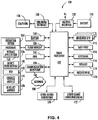
- FIG. 1 is a schematic block diagram of a communication system in accordance with an example embodiment providing load balancing techniques.
- FIGs. 2-3 are flow diagrams each illustrating example embodiment methods associated with the system of FIG. 1 .
- a communications system 30 illustratively includes a plurality of client devices 31a-31n, which are configured to generate client processing jobs such as Internet access requests, email processing jobs, calendar or address book synchronization jobs, etc.
- client processing jobs such as Internet access requests, email processing jobs, calendar or address book synchronization jobs, etc.
- Block 50 of FIG. 2 and Block 50' of FIG. 3 each method starts.
- the client device 31a is a mobile wireless communications device (i.e., a mobile device), namely a cellular device which generates and communicates its client processing jobs to a load balancer 32 via a wireless communications network 33 (illustratively represented as a cellular tower in FIG. 1 ) at Block 51 of FIG. 2 and Block 51' of FIG. 3 .
- the client device 30b is a desktop computer
- the client device 31n is a laptop computer.
- the client processing (CP) jobs are wide area network 37 (e.g., Internet) access jobs, as will be appreciated by those skilled in the art.
- Each of the client devices 31a-31n has a respective unique client identification (ID) associated therewith.
- ID may be an International Mobile Equipment Identity (IMEI) number.
- IMEI International Mobile Equipment Identity
- client IDs may be respective Internet protocol (IP) addresses, for example.
- IP Internet protocol
- Other suitable types of client IDs may also be used, as will be appreciated by those skilled in the art.
- the system 30 further illustratively includes a plurality of geographically spaced apart servers 34a-34n which are configured to process the client processing jobs.
- the servers 34a-34n may be located in different data centers. Similar to the client devices 31a-31n, each of the servers 34a-34n also has a respective unique server ID associated therewith.
- the server IDs may be IP addresses, although other suitable ID types may also be used.
- the load balancer 32 illustratively includes a client device interface module 35 configured to receive the client processing jobs from the plurality of client devices 31a-31b, at Block 52 of FIG. 2 and Block 52' of FIG. 3 .
- the load balancer 32 further illustratively includes a server interface module 36 which cooperates with the client device interface module 35 and is configured to perform load balancing for the received client jobs. More particularly, for each client processing job, the server interface module 36 generates a respective load balancing score for each server 34a-34n, at Block 53 of FIG. 2 .
- Each load balancing score is based upon the client ID of the client device 31a-31n requesting the client processing job, a hash of the server ID of each server 34a-34n, a processing load metric for each server, and a separation metric corresponding to a separation between the requesting client device and each server.
- the separation metric may correspond to a number of network nodes between the requesting client device 31a-31n and each server 34a-34n, a geographic distance between the requesting client device and each server, a network latency between the requesting client device and each server or other time or distance-based metric which can differentiate a pair of a requesting client device and a server from another pair of a requesting client device and a sever.
- the processing load metric indicates a processing load for each server 34a-34n, and may be based upon one or more factors including a number of pending client jobs, available memory, processing speed, etc., as will be appreciated by those skilled in the art.
- srv_hash is a function based upon h(Server ID), a hash of the server ID of the given server 34a-34n, and a load balancing metric.
- Score is the load balancing score and it is based on a function of the client ID, srv_hash, and a separation metric.
- the srv_hash function may be based on a function of a hash of both the server ID and the load metric, as opposed to a function of the load metric and a hash of the server ID by itself.
- the packet router 32 computes (or pre-computes upon server connection) the srv_hash function for each connected server 34a-34n, which it stores in a hash table, etc., to reduce packet routing time.
- Incoming client processing jobs (which may be in the form of packets) are passed through the Score function g(client ID, srv_hash, separation metric) for each connected server 34a-34n to compute a load balancing score for each server.
- the functions f() and g() may be chosen such that the separation and load weighting is proportional, although this need not be the case in all example embodiments.
- Example functions for f() and g() are discussed further below. By way of example, these may also be hash functions in some example embodiments.
- the processing job is assigned to the server 34 with the highest score, although in some implementations different functions may be used such that the lowest score is appropriate, for example.
- hashing functions known to those skilled in the art may be used, such as cyclic redundancy checks, checksum functions, cryptographic hash functions, etc.
- a consideration for the particular hashing (or other) function to be used is that it returns a consistent result each time a given ID is hashed therewith, as opposed to providing a pseudo-random result.
- hash values for the servers 34a-34n may be generated before hand and stored in a hash table, if desired, to expedite determination of the load balancing scores as new client processing jobs are received.
- the server interface module 36 is configured to assign each client processing job to a respective one of the servers 34a-34n based upon the load balancing scores for the client processing job, at Block 54 of FIG. 2 and Block 54' of FIG. 3 , as described above, and the job is then forwarded to and processed by the respective server, at Block 55 of FIG. 2 and Block 55' of FIG. 3 , thus concluding the method illustrated in FIG. 2 (Block 56).
- the load balancer 32 may usefully provide a preference to servers 34a-34n that have a relatively small separation with respect to a given one of the client devices 31a-31n, yet still account for server load to provide enhanced performance. That is, the load balancing will tend to "default" to one of servers 34a-34n that has the lowest separation to the given client device 31, unless that server is highly loaded.
- the load balancer 32 may therefore be implemented as a packet router.
- the packet router will have information about the clients 31a-31n, including their unique client IDs. For example, the incoming packets may be tagged with the client IDs.
- the packet router also has (or determines) information about the destination servers 34a-34n, including their unique server IDs, processing load metrics, and separation metrics.
- the packet router will perform the above-described hash-based function on each client-server pair, giving each pair a score. Once the packet router has calculated the function for each client-server pair, the client processing job is routed to the highest (or, in some example embodiments, lowest) scoring server, as appropriate for the given hashing function.
- the Fowler-Noll-Vo hash function may be employed and modified as follows:
- This particular implementation has upper and lower bounds on load (i.e., load > 0) and bounds on separation (since Java longs are 64 bytes).
- load metric is referred to as "weight”.
- a mobile device may be configured according to an IT policy.
- IT policy in general, refers to a collection of IT policy rules, in which the IT policy rules can be defined as being either grouped or non-grouped and global or per-user.
- the terms grouped, non-grouped, global and per-user are defined further below.
- Examples of applicable communication devices include pagers, cellular phones, cellular smart-phones, wireless organizers, personal digital assistants, computers, laptops, handheld wireless communication devices, wirelessly enabled notebook computers and the like.
- the mobile device is a two-way communication device with advanced data communication capabilities including the capability to communicate with other mobile devices or computer systems through a network of transceiver stations.
- the mobile device may also have the capability to allow voice communication.
- it may be referred to as a data messaging device, a two-way pager, a cellular telephone with data messaging capabilities, a wireless Internet appliance, or a data communication device (with or without telephony capabilities).
- FIGS. 4-7 To aid the reader in understanding the structure of the mobile device and how it communicates with other devices and host systems, reference will now be made to FIGS. 4-7 .
- the mobile device 100 includes a number of components such as a main processor 102 that controls the overall operation of the mobile device 100. Communication functions, including data and voice communications, are performed through a communication subsystem 104.
- the communication subsystem 104 receives messages from and sends messages to a wireless network 200.
- the communication subsystem 104 is configured in accordance with the Global System for Mobile Communication (GSM) and General Packet Radio Services (GPRS) standards.
- GSM Global System for Mobile Communication
- GPRS General Packet Radio Services
- the GSM/GPRS wireless network is used worldwide and it is expected that these standards will be superseded eventually by Enhanced Data GSM Environment (EDGE) and Universal Mobile Telecommunications Service (UMTS).
- EDGE Enhanced Data GSM Environment
- UMTS Universal Mobile Telecommunications Service
- the wireless link connecting the communication subsystem 104 with the wireless network 200 represents one or more different Radio Frequency (RF) channels, operating according to defined protocols specified for GSM/GPRS communications. With newer network protocols, these channels are capable of supporting both circuit switched voice communications and packet switched data communications.
- RF Radio Frequency
- wireless network 200 associated with mobile device 100 is a GSM/GPRS wireless network in one example implementation
- other wireless networks may also be associated with the mobile device 100 in variant implementations.
- the different types of wireless networks that may be employed include, for example, data-centric wireless networks, voice-centric wireless networks, and dual-mode networks that can support both voice and data communications over the same physical base stations.
- Combined dual-mode networks include, but are not limited to, Code Division Multiple Access (CDMA) or CDMA2000 networks, GSM/GPRS networks (as mentioned above), and future third-generation (3G) networks like EDGE and UMTS.
- Some other examples of data-centric networks include WiFi 802.11, MobitexTM and DataTACTM network communication systems.
- Examples of other voice-centric data networks include Personal Communication Systems (PCS) networks like GSM and Time Division Multiple Access (TDMA) systems.
- PCS Personal Communication Systems
- TDMA Time Division Multiple Access
- the main processor 102 also interacts with additional subsystems such as a Random Access Memory (RAM) 106, a flash memory 108, a display 110, an auxiliary input/output (I/O) subsystem 112, a data port 114, a keyboard 116, a speaker 118, a microphone 120, short-range communications 122 and other device subsystems 124.
- RAM Random Access Memory
- flash memory 108 a flash memory
- I/O auxiliary input/output subsystem
- data port 114 a data port 114
- keyboard 116 keyboard
- speaker 118 a speaker 118
- microphone 120 short-range communications 122
- short-range communications 122 short-range communications
- the display 110 and the keyboard 116 may be used for both communication-related functions, such as entering a text message for transmission over the network 200, and device-resident functions such as a calculator or task list.
- the mobile device 100 can send and receive communication signals over the wireless network 200 after required network registration or activation procedures have been completed.
- Network access is associated with a subscriber or user of the mobile device 100.
- the mobile device 100 To identify a subscriber, the mobile device 100 requires a SIM/RUIM card 126 (i.e., Subscriber Identity Module or a Removable User Identity Module) to be inserted into a SIM/RUIM interface 128 in order to communicate with a network.
- SIM/RUIM card 126 i.e., Subscriber Identity Module or a Removable User Identity Module
- the SIM card or RUIM 126 is one type of a conventional "smart card" that can be used to identify a subscriber of the mobile device 100 and to personalize the mobile device 100, among other things. Without the SIM card 126, the mobile device 100 is not fully operational for communication with the wireless network 200.
- SIM card/RUIM 126 By inserting the SIM card/RUIM 126 into the SIM/RUIM interface 128, a subscriber can access all subscribed services. Services may include: web browsing and messaging such as email, voice mail, Short Message Service (SMS), and Multimedia Messaging Services (MMS). More advanced services may include: point of sale, field service and sales force automation.
- the SIM card/RUIM 126 includes a processor and memory for storing information. Once the SIM card/RUIM 126 is inserted into the SIM/RUIM interface 128, it is coupled to the main processor 102. In order to identify the subscriber, the SIM card/RUIM 126 can include some user parameters such as an International Mobile Subscriber Identity (IMSI).
- IMSI International Mobile Subscriber Identity
- SIM card/RUIM 126 An advantage of using the SIM card/RUIM 126 is that a subscriber is not necessarily bound by any single physical mobile device.
- the SIM card/RUIM 126 may store additional subscriber information for a mobile device as well, including date book (or calendar) information and recent call information.
- user identification information can also be programmed into the flash memory 108.
- the mobile device 100 is a battery-powered device and includes a battery interface 132 for receiving one or more rechargeable batteries 130.
- the battery 130 can be a smart battery with an embedded microprocessor.
- the battery interface 132 is coupled to a regulator (not shown), which assists the battery 130 in providing power V+ to the mobile device 100.
- a regulator not shown
- future technologies such as micro fuel cells may provide the power to the mobile device 100.
- the mobile device 100 also includes an operating system 134 and software components 136 to 146 which are described in more detail below.
- the operating system 134 and the software components 136 to 146 that are executed by the main processor 102 are typically stored in a persistent store such as the flash memory 108, which may alternatively be a read-only memory (ROM) or similar storage element (not shown).
- ROM read-only memory
- portions of the operating system 134 and the software components 136 to 146 such as specific device applications, or parts thereof, may be temporarily loaded into a volatile store such as the RAM 106.
- Other software components can also be included, as is well known to those skilled in the art.
- the subset of software applications 136 that control basic device operations, including data and voice communication applications, will normally be installed on the mobile device 100 during its manufacture.
- Other software applications include a message application 138 that can be any suitable software program that allows a user of the mobile device 100 to send and receive electronic messages.
- Messages that have been sent or received by the user are typically stored in the flash memory 108 of the mobile device 100 or some other suitable storage element in the mobile device 100.
- some of the sent and received messages may be stored remotely from the device 100 such as in a data store of an associated host system that the mobile device 100 communicates with.
- the software applications can further include a device state module 140, a Personal Information Manager (PIM) 142, and other suitable modules (not shown).
- the device state module 140 provides persistence, i.e., the device state module 140 ensures that important device data is stored in persistent memory, such as the flash memory 108, so that the data is not lost when the mobile device 100 is turned off or loses power.
- the PIM 142 includes functionality for organizing and managing data items of interest to the user, such as, but not limited to, email, contacts, calendar events, voice mails, appointments, and task items.
- a PIM application has the ability to send and receive data items via the wireless network 200.
- PIM data items may be seamlessly integrated, synchronized, and updated via the wireless network 200 with the mobile device subscriber's corresponding data items stored and/or associated with a host computer system. This functionality creates a mirrored host computer on the mobile device 100 with respect to such items. This can be particularly advantageous when the host computer system is the mobile device subscriber's office computer system.
- the mobile device 100 also includes a connect module 144, and an IT policy module 146.
- the connect module 144 implements the communication protocols that are required for the mobile device 100 to communicate with the wireless infrastructure and any host system, such as an enterprise system, that the mobile device 100 is authorized to interface with. Examples of a wireless infrastructure and an enterprise system are given in FIGS. 6 and 7 , which are described in more detail below.
- the connect module 144 includes a set of APIs that can be integrated with the mobile device 100 to allow the mobile device 100 to use any number of services associated with the enterprise system.
- the connect module 144 allows the mobile device 100 to establish an end-to-end secure, authenticated communication pipe with the host system.
- a subset of applications for which access is provided by the connect module 144 can be used to pass IT policy commands from the host system to the mobile device 100. This can be done in a wireless or wired manner.
- These instructions can then be passed to the IT policy module 146 to modify the configuration of the device 100. Alternatively, in some cases, the IT policy update can also be done over a wired connection.
- the IT policy module 146 receives IT policy data that encodes the IT policy.
- the IT policy module 146 then ensures that the IT policy data is authenticated by the mobile device 100.
- the IT policy data can then be stored in the flash memory 106 in its native form. After the IT policy data is stored, a global notification can be sent by the IT policy module 146 to all of the applications residing on the mobile device 100. Applications for which the IT policy may be applicable then respond by reading the IT policy data to look for IT policy rules that are applicable.
- the IT policy module 146 can include a parser (not shown), which can be used by the applications to read the IT policy rules. In some cases, another module or application can provide the parser. Grouped IT policy rules, described in more detail below, are retrieved as byte streams, which are then sent (recursively, in a sense) into the parser to determine the values of each IT policy rule defined within the grouped IT policy rule. In at least some example embodiments, the IT policy module 146 can determine which applications are affected by the IT policy data and send a notification to only those applications. In either of these cases, for applications that aren't running at the time of the notification, the applications can call the parser or the IT policy module 146 when they are executed to determine if there are any relevant IT policy rules in the newly received IT policy data.
- All applications that support rules in the IT Policy are coded to know the type of data to expect.
- the value that is set for the "WEP User Name” IT policy rule is known to be a string; therefore the value in the IT policy data that corresponds to this rule is interpreted as a string.
- the setting for the "Set Maximum Password Attempts" IT policy rule is known to be an integer, and therefore the value in the IT policy data that corresponds to this rule is interpreted as such.
- the IT policy module 146 After the IT policy rules have been applied to the applicable applications or configuration files, the IT policy module 146 sends an acknowledgement back to the host system to indicate that the IT policy data was received and successfully applied.
- software applications can also be installed on the mobile device 100.
- These software applications can be third party applications, which are added after the manufacture of the mobile device 100. Examples of third party applications include games, calculators, utilities, etc.
- the additional applications can be loaded onto the mobile device 100 through at least one of the wireless network 200, the auxiliary I/O subsystem 112, the data port 114, the short-range communications subsystem 122, or any other suitable device subsystem 124.
- This flexibility in application installation increases the functionality of the mobile device 100 and may provide enhanced on-device functions, communication-related functions, or both.
- secure communication applications may enable electronic commerce functions and other such financial transactions to be performed using the mobile device 100.
- the data port 114 enables a subscriber to set preferences through an external device or software application and extends the capabilities of the mobile device 100 by providing for information or software downloads to the mobile device 100 other than through a wireless communication network.
- the alternate download path may, for example, be used to load an encryption key onto the mobile device 100 through a direct and thus reliable and trusted connection to provide secure device communication.
- the data port 114 can be any suitable port that enables data communication between the mobile device 100 and another computing device.
- the data port 114 can be a serial or a parallel port.
- the data port 114 can be a USB port that includes data lines for data transfer and a supply line that can provide a charging current to charge the battery 130 of the mobile device 100.
- the short-range communications subsystem 122 provides for communication between the mobile device 100 and different systems or devices, without the use of the wireless network 200.
- the subsystem 122 may include an infrared device and associated circuits and components for short-range communication.
- Examples of short-range communication standards include standards developed by the Infrared Data Association (IrDA), Bluetooth, and the 802.11 family of standards developed by IEEE.
- a received signal such as a text message, an email message, or web page download will be processed by the communication subsystem 104 and input to the main processor 102.
- the main processor 102 will then process the received signal for output to the display 110 or alternatively to the auxiliary I/O subsystem 112.
- a subscriber may also compose data items, such as email messages, for example, using the keyboard 116 in conjunction with the display 110 and possibly the auxiliary I/O subsystem 112.
- the auxiliary subsystem 112 may include devices such as: a touch screen, mouse, track ball, infrared fingerprint detector, or a roller wheel with dynamic button pressing capability.
- the keyboard 116 is preferably an alphanumeric keyboard and/or telephone-type keypad. However, other types of keyboards may also be used.
- a composed item may be transmitted over the wireless network 200 through the communication subsystem 104.
- the overall operation of the mobile device 100 is substantially similar, except that the received signals are output to the speaker 118, and signals for transmission are generated by the microphone 120.
- Alternative voice or audio I/O subsystems such as a voice message recording subsystem, can also be implemented on the mobile device 100.
- voice or audio signal output is accomplished primarily through the speaker 118, the display 110 can also be used to provide additional information such as the identity of a calling party, duration of a voice call, or other voice call related information.
- the communication subsystem 104 includes a receiver 150, a transmitter 152, as well as associated components such as one or more embedded or internal antenna elements 154 and 156, Local Oscillators (LOs) 158, and a processing module such as a Digital Signal Processor (DSP) 160.
- LOs Local Oscillators
- DSP Digital Signal Processor
- Signals received by the antenna 154 through the wireless network 200 are input to the receiver 150, which may perform such common receiver functions as signal amplification, frequency down conversion, filtering, channel selection, and analog-to-digital (A/D) conversion.
- A/D conversion of a received signal allows more complex communication functions such as demodulation and decoding to be performed in the DSP 160.
- signals to be transmitted are processed, including modulation and encoding, by the DSP 160.
- These DSP-processed signals are input to the transmitter 152 for digital-to-analog (D/A) conversion, frequency up conversion, filtering, amplification and transmission over the wireless network 200 via the antenna 156.
- the DSP 160 not only processes communication signals, but also provides for receiver and transmitter control. For example, the gains applied to communication signals in the receiver 150 and the transmitter 152 may be adaptively controlled through automatic gain control algorithms implemented in the DSP 160.
- the wireless link between the mobile device 100 and the wireless network 200 can contain one or more different channels, typically different RF channels, and associated protocols used between the mobile device 100 and the wireless network 200.
- An RF channel is a limited resource that must be conserved, typically due to limits in overall bandwidth and limited battery power of the mobile device 100.
- the transmitter 152 When the mobile device 100 is fully operational, the transmitter 152 is typically keyed or turned on only when it is transmitting to the wireless network 200 and is otherwise turned off to conserve resources. Similarly, the receiver 150 is periodically turned off to conserve power until it is needed to receive signals or information (if at all) during designated time periods.
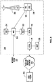
- the wireless network 200 includes one or more nodes 202.
- the mobile device 100 can communicate with the node 202 within the wireless network 200.
- the node 202 is configured in accordance with General Packet Radio Service (GPRS) and Global Systems for Mobile (GSM) technologies.
- GPRS General Packet Radio Service
- GSM Global Systems for Mobile
- the node 202 includes a base station controller (BSC) 204 with an associated tower station 206, a Packet Control Unit (PCU) 208 added for GPRS support in GSM, a Mobile Switching Center (MSC) 210, a Home Location Register (HLR) 212, a Visitor Location Registry (VLR) 214, a Serving GPRS Support Node (SGSN) 216, a Gateway GPRS Support Node (GGSN) 218, and a Dynamic Host Configuration Protocol (DHCP) 220.
- BSC base station controller
- PCU Packet Control Unit
- MSC Mobile Switching Center
- HLR Home Location Register
- VLR Visitor Location Registry
- SGSN Serving GPRS Support Node
- GGSN Gateway GPRS Support Node
- DHCP Dynamic Host Configuration Protocol
- the MSC 210 is coupled to the BSC 204 and to a landline network, such as a Public Switched Telephone Network (PSTN) 222 to satisfy circuit switched requirements.
- PSTN Public Switched Telephone Network
- the connection through the PCU 208, the SGSN 216 and the GGSN 218 to a public or private network (Internet) 224 (also referred to herein generally as a shared network infrastructure) represents the data path for GPRS capable mobile devices.
- the BSC 204 also contains the Packet Control Unit (PCU) 208 that connects to the SGSN 216 to control segmentation, radio channel allocation and to satisfy packet switched requirements.
- PCU Packet Control Unit
- the HLR 212 is shared between the MSC 210 and the SGSN 216. Access to the VLR 214 is controlled by the MSC 210.
- the station 206 is a fixed transceiver station and together with the BSC 204 form fixed transceiver equipment.
- the fixed transceiver equipment provides wireless network coverage for a particular coverage area commonly referred to as a "cell.”
- the fixed transceiver equipment transmits communication signals to and receives communication signals from mobile devices within its cell via the station 206.
- the fixed transceiver equipment normally performs such functions as modulation and possibly encoding and/or encryption of signals to be transmitted to the mobile device 100 in accordance with particular, usually predetermined, communication protocols and parameters, under control of its controller.
- the fixed transceiver equipment similarly demodulates and possibly decodes and decrypts, if necessary, any communication signals received from the mobile device 100 within its cell. Communication protocols and parameters may vary between different nodes. For example, one node may employ a different modulation scheme and operate at different frequencies than other nodes.
- the HLR 212 For all mobile devices 100 registered with a specific network, permanent configuration data such as a user profile is stored in the HLR 212.
- the HLR 212 also contains location information for each registered mobile device and can be queried to determine the current location of a mobile device.
- the MSC 210 is responsible for a group of location areas and stores the data of the mobile devices currently in its area of responsibility in the VLR 214.
- the VLR 214 also contains information on mobile devices that are visiting other networks.
- the information in the VLR 214 includes part of the permanent mobile device data transmitted from the HLR 212 to the VLR 214 for faster access. By moving additional information from a remote HLR 212 node to the VLR 214, the amount of traffic between these nodes can be reduced so that voice and data services can be provided with faster response times and at the same time requiring less use of computing resources.
- the SGSN 216 and the GGSN 218 are elements added for GPRS support, namely packet switched data support, within GSM.
- the SGSN 216 and the MSC 210 have similar responsibilities within the wireless network 200 by keeping track of the location of each mobile device 100.
- the SGSN 216 also performs security functions and access control for data traffic on the wireless network 200.
- the GGSN 218 provides internetworking connections with external packet switched networks and connects to one or more SGSN's 216 via an Internet Protocol (IP) backbone network operated within the network 200.
- IP Internet Protocol
- a given mobile device 100 must perform a "GPRS Attach" to acquire an IP address and to access data services.
- Integrated Services Digital Network ISDN addresses are used for routing incoming and outgoing calls.
- ISDN Integrated Services Digital Network
- GPRS capable networks use private, dynamically assigned IP addresses, thus requiring the DHCP server 220 connected to the GGSN 218.
- RADIUS Remote Authentication Dial-In User Service
- APN Access Point Node
- the APN represents a logical end of an IP tunnel that can either access direct Internet compatible services or private network connections.
- the APN also represents a security mechanism for the network 200, insofar as each mobile device 100 must be assigned to one or more APNs and mobile devices 100 cannot exchange data without first performing a GPRS Attach to an APN that it has been authorized to use.
- the APN may be considered to be similar to an Internet domain name such as "myconnection.wireless.com".
- IPsec IP Security
- VPN Virtual Private Networks
- PDP Packet Data Protocol
- the network 200 will run an idle timer for each PDP Context to determine if there is a lack of activity.
- the PDP Context can be de-allocated and the IP address returned to the IP address pool managed by the DHCP server 220.
- FIG. 7 shown therein is a block diagram illustrating components of an example configuration of a host system 250 that the mobile device 100 can communicate with in conjunction with the connect module 144.
- the host system 250 will typically be a corporate enterprise or other local area network (LAN), but may also be a home office computer or some other private system, for example, in variant implementations.
- the host system 250 is depicted as a LAN of an organization to which a user of the mobile device 100 belongs.
- a plurality of mobile devices can communicate wirelessly with the host system 250 through one or more nodes 202 of the wireless network 200.
- the host system 250 includes a number of network components connected to each other by a network 260.
- a user's desktop computer 262a with an accompanying cradle 264 for the user's mobile device 100 is situated on a LAN connection.
- the cradle 264 for the mobile device 100 can be coupled to the computer 262a by a serial or a Universal Serial Bus (USB) connection, for example.
- Other user computers 262b-262n are also situated on the network 260, and each may or may not be equipped with an accompanying cradle 264.
- the cradle 264 facilitates the loading of information (e.g., PIM data, private symmetric encryption keys to facilitate secure communications) from the user computer 262a to the mobile device 100, and may be particularly useful for bulk information updates often performed in initializing the mobile device 100 for use.
- information downloaded to the mobile device 100 may include certificates used in the exchange of messages.
- the user computers 262a-262n will typically also be connected to other peripheral devices, such as printers, etc. which are not explicitly shown in FIG. 7 .
- peripheral devices such as printers, etc.
- FIG. 4 only a subset of network components of the host system 250 are shown in FIG. 4 for ease of exposition, and it will be understood by persons skilled in the art that the host system 250 will include additional components that are not explicitly shown in FIG. 5 for this example configuration. More generally, the host system 250 may represent a smaller part of a larger network (not shown) of the organization, and may include different components and/or be arranged in different topologies than that shown in the example embodiment of FIG. 7 .
- the wireless communication support components 270 can include a message management server 272, a mobile data server 274, a contact server 276, and a device manager module 278.
- the device manager module 278 includes an IT Policy editor 280 and an IT user property editor 282, as well as other software components for allowing an IT administrator to configure the mobile devices 100.
- the support components 270 also include a data store 284, and an IT policy server 286.
- the IT policy server 286 includes a processor 288, a network interface 290 and a memory unit 292.
- the processor 288 controls the operation of the IT policy server 286 and executes functions related to the standardized IT policy as described below.
- the network interface 290 allows the IT policy server 286 to communicate with the various components of the host system 250 and the mobile devices 100.
- the memory unit 292 can store functions used in implementing the IT policy as well as related data. Those skilled in the art know how to implement these various components. Other components may also be included as is well known to those skilled in the art. Further, in some implementations, the data store 284 can be part of any one of the servers.
- the mobile device 100 communicates with the host system 250 through node 202 of the wireless network 200 and a shared network infrastructure 224 such as a service provider network or the public Internet. Access to the host system 250 may be provided through one or more routers (not shown), and computing devices of the host system 250 may operate from behind a firewall or proxy server 266.
- the proxy server 266 provides a secure node and a wireless internet gateway for the host system 250. The proxy server 266 intelligently routes data to the correct destination server within the host system 250.
- the host system 250 can include a wireless VPN router (not shown) to facilitate data exchange between the host system 250 and the mobile device 100.
- the wireless VPN router allows a VPN connection to be established directly through a specific wireless network to the mobile device 100.
- the wireless VPN router can be used with the Internet Protocol (IP) Version 6 (IPV6) and IP-based wireless networks. This protocol can provide enough IP addresses so that each mobile device has a dedicated IP address, making it possible to push information to a mobile device at any time.
- IP Internet Protocol
- IPV6 Internet Protocol Version 6
- Messages intended for a user of the mobile device 100 are initially received by a message server 268 of the host system 250.
- Such messages may originate from any number of sources.
- a message may have been sent by a sender from the computer 262b within the host system 250, from a different mobile device (not shown) connected to the wireless network 200 or a different wireless network, or from a different computing device, or other device capable of sending messages, via the shared network infrastructure 224, possibly through an application service provider (ASP) or Internet service provider (ISP), for example.
- ASP application service provider
- ISP Internet service provider
- the message server 268 typically acts as the primary interface for the exchange of messages, particularly email messages, within the organization and over the shared network infrastructure 224. Each user in the organization that has been set up to send and receive messages is typically associated with a user account managed by the message server 268.
- Some example implementations of the message server 268 include a Microsoft ExchangeTM server, a Lotus DominoTM server, a Novell GroupwiseTM server, or another suitable mail server installed in a corporate environment.
- the host system 250 may include multiple message servers 268.
- the message server 268 may also be adapted to provide additional functions beyond message management, including the management of data associated with calendars and task lists, for example.
- messages When messages are received by the message server 268, they are typically stored in a data store associated with the message server 268.
- the data store may be a separate hardware unit, such as data store 284, that the message server 268 communicates with. Messages can be subsequently retrieved and delivered to users by accessing the message server 268.
- an email client application operating on a user's computer 262a may request the email messages associated with that user's account stored on the data store associated with the message server 268. These messages are then retrieved from the data store and stored locally on the computer 262a.
- the data store associated with the message server 268 can store copies of each message that is locally stored on the mobile device 100.
- the data store associated with the message server 268 can store all of the messages for the user of the mobile device 100 and only a smaller number of messages can be stored on the mobile device 100 to conserve memory. For instance, the most recent messages (i.e., those received in the past two to three months for example) can be stored on the mobile device 100.
- the message application 138 operating on the mobile device 100 may also request messages associated with the user's account from the message server 268.
- the message application 138 may be configured (either by the user or by an administrator, possibly in accordance with an organization's information technology (IT) policy) to make this request at the direction of the user, at some pre-defined time interval, or upon the occurrence of some pre-defined event.
- the mobile device 100 is assigned its own email address, and messages addressed specifically to the mobile device 100 are automatically redirected to the mobile device 100 as they are received by the message server 268.
- the message management server 272 can be used to specifically provide support for the management of messages, such as email messages, that are to be handled by mobile devices. Generally, while messages are still stored on the message server 268, the message management server 272 can be used to control when, if, and how messages are sent to the mobile device 100. The message management server 272 also facilitates the handling of messages composed on the mobile device 100, which are sent to the message server 268 for subsequent delivery.
- the message management server 272 may monitor the user's "mailbox" (e.g., the message store associated with the user's account on the message server 268 ) for new email messages, and apply user-definable filters to new messages to determine if and how the messages are relayed to the user's mobile device 100.
- the message management server 272 may also compress and encrypt new messages (e.g., using an encryption technique such as Data Encryption Standard (DES), Triple DES, or Advanced Encryption Standard (AES)) and push them to the mobile device 100 via the shared network infrastructure 224 and the wireless network 200.
- DES Data Encryption Standard
- Triple DES Triple DES
- AES Advanced Encryption Standard
- the message management server 272 may also receive messages composed on the mobile device 100 (e.g., encrypted using Triple DES), decrypt and decompress the composed messages, re-format the composed messages if desired so that they will appear to have originated from the user's computer 262a, and re-route the composed messages to the message server 268 for delivery.
- messages composed on the mobile device 100 e.g., encrypted using Triple DES
- Certain properties or restrictions associated with messages that are to be sent from and/or received by the mobile device 100 can be defined (e.g., by an administrator in accordance with IT policy) and enforced by the message management server 272. These may include whether the mobile device 100 may receive encrypted and/or signed messages, minimum encryption key sizes, whether outgoing messages must be encrypted and/or signed, and whether copies of all secure messages sent from the mobile device 100 are to be sent to a pre-defined copy address, for example.
- the message management server 272 may also be adapted to provide other control functions, such as only pushing certain message information or pre-defined portions (e.g., "blocks") of a message stored on the message server 268 to the mobile device 100. For example, in some cases, when a message is initially retrieved by the mobile device 100 from the message server 268, the message management server 272 may push only the first part of a message to the mobile device 100, with the part being of a pre-defined size (e.g., 2 KB). The user can then request that more of the message be delivered in similar-sized blocks by the message management server 272 to the mobile device 100, possibly up to a maximum predefined message size. Accordingly, the message management server 272 facilitates better control over the type of data and the amount of data that is communicated to the mobile device 100, and can help to minimize potential waste of bandwidth or other resources.
- pre-defined portions e.g., "blocks”
- the mobile data server 274 encompasses any other server that stores information that is relevant to the corporation.
- the mobile data server 274 may include, but is not limited to, databases, online data document repositories, customer relationship management (CRM) systems, or enterprise resource planning (ERP) applications.
- CRM customer relationship management
- ERP enterprise resource planning
- the contact server 276 can provide information for a list of contacts for the user in a similar fashion as the address book on the mobile device 100. Accordingly, for a given contact, the contact server 276 can include the name, phone number, work address and email address of the contact, among other information. The contact server 276 can also provide a global address list that contains the contact information for all of the contacts associated with the host system 250.
- the message management server 272, the mobile data server 274, the contact server 276, the device manager module 278, the data store 284 and the IT policy server 286 do not need to be implemented on separate physical servers within the host system 250.
- some or all of the functions associated with the message management server 272 may be integrated with the message server 268, or some other server in the host system 250.
- the host system 250 may include multiple message management servers 272, particularly in variant implementations where a large number of mobile devices need to be supported.
- the IT policy server 286 can provide the IT policy editor 280, the IT user property editor 282 and the data store 284. In some cases, the IT policy server 286 can also provide the device manager module 278.
- the processor 288 of the IT policy server 286 can be used to perform the various steps of a method for providing IT policy data that is customizable on a per-user basis.
- the processor 288 can execute the editors 280 and 282. In some cases, the functionality of the editors 280 and 282 can be provided by a single editor. In some cases, the memory unit 292 can provide the data store 284.
- the device manager module 278 provides an IT administrator with a graphical user interface with which the IT administrator interacts to configure various settings for the mobile devices 100.
- the IT administrator can use IT policy rules to define behaviors of certain applications on the mobile device 100 that are permitted such as phone, web browser or Instant Messenger use.
- the IT policy rules can also be used to set specific values for configuration settings that an organization requires on the mobile devices 100 such as auto signature text, WLAN/VoIP/VPN configuration, security requirements (e.g., encryption algorithms, password rules, etc.), specifying themes or applications that are allowed to run on the mobile device 100, and the like.
Claims (10)
- Lastausgleicher (32), der konfiguriert ist zum:Empfangen von Client-Verarbeitungsjobs von mehreren Client-Vorrichtungen (31a-31n), die dazu konfiguriert sind, Client-Verarbeitungsjobs zu erzeugen, und jeweils eine damit assoziierte jeweilige einzigartige Client-Identifikation (Client-ID) aufweisen;für jeden Client-Verarbeitungsjob Erzeugen einer jeweiligen Lastausgleich-Wertung für jeden Server von mehreren geografisch beabstandeten Servern (34a-34n), die dazu konfiguriert sind, die Client-Verarbeitungsjobs zu verarbeiten, und jeweils eine damit assoziierte jeweilige eindeutige Server-ID aufweisen, wobei die Lastausgleich-Wertung von der Client-ID der Client-Vorrichtung, die den Client-Verarbeitungsjob anfordert, einem Hash der Server-ID jedes Servers, einer Verarbeitungslastmetrik für jeden Server und einer Trennungsmetrik, die einer Trennung zwischen der anfordernden Client-Vorrichtung und jedem Server entspricht, abhängt; undZuordnen jedes Client-Verarbeitungsjobs einem jeweiligen Server auf der Basis der Lastausgleich-Wertungen für den Client-Verarbeitungsjob.
- Lastausgleicher (32) nach Anspruch 1, wobei die Trennungsmetrik einer Anzahl von Netzknoten zwischen der anfordernden Client-Vorrichtung (31a) und jedem Server entspricht.
- Lastausgleicher (32) nach Anspruch 1, wobei die Trennungsmetrik einem geografischen Abstand zwischen der anfordernden Client-Vorrichtung (31b) und jedem Server entspricht.
- Lastausgleicher (32) nach Anspruch 1, wobei die Trennungsmetrik einer Netzlatenz zwischen der anfordernden Client-Vorrichtung (31b) und jedem Sever entspricht.
- Lastausgleicher (32) nach Anspruch 1, wobei der Lastausgleicher (32) dazu konfiguriert ist, jeden Client-Verarbeitungsjob einem jeweiligen Server mit einer höchsten Lastausgleich-Wertung von den Lastausgleich-Wertungen für den Client-Verarbeitungsjobs zuzuordnen.
- Lastausgleichsverfahren für mehrere Client-Vorrichtungen (31a-31n), die dazu konfiguriert sind, Client-Verarbeitungsjobs zu erzeugen, und jeweils eine damit assoziierte jeweilige einzigartige Client-Identifikation (Client-ID) aufweisen, und mehrere geografisch beabstandete Server (34a-34n), die dazu konfiguriert sind, die Client-Verarbeitungsjobs zu verarbeiten, und jeweils eine damit assoziierte jeweilige eindeutige Server-ID aufweisen, wobei das Verfahren umfasst:Empfangen der Client-Verarbeitungsjobs von den mehreren Client-Vorrichtungen an einem Client-Vorrichtungsschnittstellenmodul;für jeden Client-Verarbeitungsjob Erzeugen einer jeweiligen Lastausgleich-Wertung für jeden Server, wobei die Lastausgleich-Wertung von der Client-ID der Client-Vorrichtung (31b), die den Client-Verarbeitungsjob anfordert, einem Hash der Server-ID jedes Servers, einer Verarbeitungslastmetrik für jeden Server und einer Trennungsmetrik, die einer Trennung zwischen der anfordernden Client-Vorrichtung und jedem Server an einem Serverschnittstellenmodul entspricht, abhängt; undZuordnen jedes Client-Verarbeitungsjobs einem jeweiligen Server auf der Basis der Lastausgleich-Wertungen für den Client-Verarbeitungsjob.
- Verfahren nach Anspruch 6, wobei die Trennungsmetrik einer Anzahl von Netzknoten zwischen der anfordernden Client-Vorrichtung (31b) und jedem Server entspricht.
- Verfahren nach Anspruch 6, wobei die Trennungsmetrik einem geografischen Abstand zwischen der anfordernden Client-Vorrichtung und jedem Server entspricht.
- Verfahren nach Anspruch 6, wobei die Trennungsmetrik einer Netzlatenz zwischen der anfordernden Client-Vorrichtung (31b) und jedem Sever entspricht.
- Kommunikationssystem (30), umfassend:mehrere Client-Vorrichtungen (31a-31n), die dazu konfiguriert sind, Client-Verarbeitungsjobs zu erzeugen, und jeweils eine damit assoziierte jeweilige einzigartige Client-Identifikation (Client-ID) aufweisen;mehrere geografisch beabstandete Server (34a-34n), die dazu konfiguriert sind, die Client-Verarbeitungsjobs zu verarbeiten, und jeweils eine damit assoziierte jeweilige eindeutige Server-ID aufweisen; undeinen Lastausgleicher (32) gemäß einem der Ansprüche 1 bis 5.
Priority Applications (2)
| Application Number | Priority Date | Filing Date | Title |
|---|---|---|---|
| EP10155993.8A EP2365675B1 (de) | 2010-03-09 | 2010-03-09 | Kommunikationssystem zur bereitstellung eines server-lastausgleichs basierend auf last- und getrenntheitsmetriken und verfahren dafür |
| CA2733625A CA2733625C (en) | 2010-03-09 | 2011-03-09 | Communications system providing server load balancing based upon load and separation metrics and related methods |
Applications Claiming Priority (1)
| Application Number | Priority Date | Filing Date | Title |
|---|---|---|---|
| EP10155993.8A EP2365675B1 (de) | 2010-03-09 | 2010-03-09 | Kommunikationssystem zur bereitstellung eines server-lastausgleichs basierend auf last- und getrenntheitsmetriken und verfahren dafür |
Publications (2)
| Publication Number | Publication Date |
|---|---|
| EP2365675A1 EP2365675A1 (de) | 2011-09-14 |
| EP2365675B1 true EP2365675B1 (de) | 2018-01-10 |
Family
ID=42561175
Family Applications (1)
| Application Number | Title | Priority Date | Filing Date |
|---|---|---|---|
| EP10155993.8A Active EP2365675B1 (de) | 2010-03-09 | 2010-03-09 | Kommunikationssystem zur bereitstellung eines server-lastausgleichs basierend auf last- und getrenntheitsmetriken und verfahren dafür |
Country Status (2)
| Country | Link |
|---|---|
| EP (1) | EP2365675B1 (de) |
| CA (1) | CA2733625C (de) |
Families Citing this family (5)
| Publication number | Priority date | Publication date | Assignee | Title |
|---|---|---|---|---|
| US9277005B2 (en) * | 2013-01-09 | 2016-03-01 | Edgecast Networks, Inc. | Optimized consistent request distribution for balanced load distribution in a content delivery network |
| US9548000B2 (en) * | 2013-03-21 | 2017-01-17 | Telecommunication Systems, Inc. | Scoring server |
| US9894023B2 (en) * | 2014-07-15 | 2018-02-13 | Zebrafish Labs, Inc. | Image feeding server network |
| JP6251702B2 (ja) | 2015-05-26 | 2017-12-20 | エヌ・ティ・ティ・コミュニケーションズ株式会社 | 接続先サーバ指示装置、サービス利用システム、接続先サーバ指示方法、及びプログラム |
| CN105208133B (zh) * | 2015-10-20 | 2018-05-25 | 上海斐讯数据通信技术有限公司 | 一种服务器、负载均衡器以及服务器负载均衡方法和系统 |
Citations (1)
| Publication number | Priority date | Publication date | Assignee | Title |
|---|---|---|---|---|
| US7020698B2 (en) * | 2000-05-31 | 2006-03-28 | Lucent Technologies Inc. | System and method for locating a closest server in response to a client domain name request |
Family Cites Families (3)
| Publication number | Priority date | Publication date | Assignee | Title |
|---|---|---|---|---|
| US6006264A (en) * | 1997-08-01 | 1999-12-21 | Arrowpoint Communications, Inc. | Method and system for directing a flow between a client and a server |
| US7162539B2 (en) * | 2000-03-16 | 2007-01-09 | Adara Networks, Inc. | System and method for discovering information objects and information object repositories in computer networks |
| AR028658A1 (es) * | 2000-06-01 | 2003-05-21 | Aerocast Com Inc | Metodo de indicacion de buen estado holistico y aparato de distribucion de posibilidad de indicacion. |
-
2010
- 2010-03-09 EP EP10155993.8A patent/EP2365675B1/de active Active
-
2011
- 2011-03-09 CA CA2733625A patent/CA2733625C/en active Active
Patent Citations (1)
| Publication number | Priority date | Publication date | Assignee | Title |
|---|---|---|---|---|
| US7020698B2 (en) * | 2000-05-31 | 2006-03-28 | Lucent Technologies Inc. | System and method for locating a closest server in response to a client domain name request |
Also Published As
| Publication number | Publication date |
|---|---|
| CA2733625A1 (en) | 2011-09-09 |
| EP2365675A1 (de) | 2011-09-14 |
| CA2733625C (en) | 2016-02-23 |
Similar Documents
| Publication | Publication Date | Title |
|---|---|---|
| US8578027B2 (en) | Communications system providing server load balancing based upon load and separation metrics and related methods | |
| EP2175614B1 (de) | System und Verfahren zur Konfiguration einer Aktualisierungsfrequenz für Anwendungsaktualisierungen mobiler drahtloser Kommunikationsvorrichtungen und zugehörige Verfahren | |
| US8463859B2 (en) | Email system including synchronization server(s) providing synchronization based upon synchronization indicators stored on mobile devices and related methods | |
| US20180322488A1 (en) | Communication system with multi-feature integrated digital wallet graphical user interface and related methods | |
| US20120239949A1 (en) | Electronic device and method for application and profile sensitive battery power management | |
| US20070118558A1 (en) | System and method for application program operation on a wireless device | |
| EP2365675B1 (de) | Kommunikationssystem zur bereitstellung eines server-lastausgleichs basierend auf last- und getrenntheitsmetriken und verfahren dafür | |
| US20130018915A1 (en) | Mobile wireless communications device with search shortcut and related methods | |
| US8572287B2 (en) | Method and apparatus for communicating compression state information for interactive compression | |
| US8793320B2 (en) | Communications system with polling server providing dynamic record ID polling and related methods | |
| US20080301290A1 (en) | Method and apparatus for management of common side information | |
| US8977320B2 (en) | Mobile wireless communications device with user navigation using an antenna and related methods | |
| EP1788505A1 (de) | System und Verfahren zum Betrieb eines Anwenderprogramms bei einer drahtlosen Vorrichtung | |
| US20130172014A1 (en) | Wireless communication system with potential new contacts and related methods | |
| EP2405618B1 (de) | E-Mail-System mit Synchronisierungsserver(n) zur Synchronisierung auf Grundlage von auf mobilen Vorrichtungen gespeicherten Synchronisierungsindikatoren und zugehörige Verfahren | |
| US9043390B2 (en) | Communication system with PIM entry synchronization and related methods | |
| US8949384B2 (en) | Communication system with server for identification information retrieval and related methods | |
| EP2104306B1 (de) | Verfahren und Vorrichtung zur Kommunikation von Kompressionsstatusinformationen für interaktive Kompression | |
| US8621014B2 (en) | Mobile wireless communications device for storing e-mail search results and associated methods | |
| US20130191378A1 (en) | Wireless communication system with server providing search facts and related methods | |
| CA2693729A1 (en) | Communications system with polling server providing dynamic record id polling and related methods |
Legal Events
| Date | Code | Title | Description |
|---|---|---|---|
| PUAI | Public reference made under article 153(3) epc to a published international application that has entered the european phase |
Free format text: ORIGINAL CODE: 0009012 |
|
| 17P | Request for examination filed |
Effective date: 20100315 |
|
| AK | Designated contracting states |
Kind code of ref document: A1 Designated state(s): AT BE BG CH CY CZ DE DK EE ES FI FR GB GR HR HU IE IS IT LI LT LU LV MC MK MT NL NO PL PT RO SE SI SK SM TR |
|
| AX | Request for extension of the european patent |
Extension state: AL BA ME RS |
|
| 17Q | First examination report despatched |
Effective date: 20120705 |
|
| RAP1 | Party data changed (applicant data changed or rights of an application transferred) |
Owner name: BLACKBERRY LIMITED |
|
| RAP1 | Party data changed (applicant data changed or rights of an application transferred) |
Owner name: BLACKBERRY LIMITED |
|
| GRAP | Despatch of communication of intention to grant a patent |
Free format text: ORIGINAL CODE: EPIDOSNIGR1 |
|
| INTG | Intention to grant announced |
Effective date: 20170316 |
|
| GRAJ | Information related to disapproval of communication of intention to grant by the applicant or resumption of examination proceedings by the epo deleted |
Free format text: ORIGINAL CODE: EPIDOSDIGR1 |
|
| GRAP | Despatch of communication of intention to grant a patent |
Free format text: ORIGINAL CODE: EPIDOSNIGR1 |
|
| INTC | Intention to grant announced (deleted) | ||
| INTG | Intention to grant announced |
Effective date: 20170720 |
|
| GRAS | Grant fee paid |
Free format text: ORIGINAL CODE: EPIDOSNIGR3 |
|
| GRAA | (expected) grant |
Free format text: ORIGINAL CODE: 0009210 |
|
| AK | Designated contracting states |
Kind code of ref document: B1 Designated state(s): AT BE BG CH CY CZ DE DK EE ES FI FR GB GR HR HU IE IS IT LI LT LU LV MC MK MT NL NO PL PT RO SE SI SK SM TR |
|
| REG | Reference to a national code |
Ref country code: GB Ref legal event code: FG4D |
|
| REG | Reference to a national code |
Ref country code: CH Ref legal event code: EP Ref country code: AT Ref legal event code: REF Ref document number: 963603 Country of ref document: AT Kind code of ref document: T Effective date: 20180115 |
|
| REG | Reference to a national code |
Ref country code: IE Ref legal event code: FG4D |
|
| REG | Reference to a national code |
Ref country code: DE Ref legal event code: R096 Ref document number: 602010047889 Country of ref document: DE |
|
| REG | Reference to a national code |
Ref country code: FR Ref legal event code: PLFP Year of fee payment: 9 |
|
| REG | Reference to a national code |
Ref country code: NL Ref legal event code: MP Effective date: 20180110 |
|
| REG | Reference to a national code |
Ref country code: AT Ref legal event code: MK05 Ref document number: 963603 Country of ref document: AT Kind code of ref document: T Effective date: 20180110 |
|
| PG25 | Lapsed in a contracting state [announced via postgrant information from national office to epo] |
Ref country code: NL Free format text: LAPSE BECAUSE OF FAILURE TO SUBMIT A TRANSLATION OF THE DESCRIPTION OR TO PAY THE FEE WITHIN THE PRESCRIBED TIME-LIMIT Effective date: 20180110 |
|
| PG25 | Lapsed in a contracting state [announced via postgrant information from national office to epo] |
Ref country code: NO Free format text: LAPSE BECAUSE OF FAILURE TO SUBMIT A TRANSLATION OF THE DESCRIPTION OR TO PAY THE FEE WITHIN THE PRESCRIBED TIME-LIMIT Effective date: 20180410 Ref country code: FI Free format text: LAPSE BECAUSE OF FAILURE TO SUBMIT A TRANSLATION OF THE DESCRIPTION OR TO PAY THE FEE WITHIN THE PRESCRIBED TIME-LIMIT Effective date: 20180110 Ref country code: LT Free format text: LAPSE BECAUSE OF FAILURE TO SUBMIT A TRANSLATION OF THE DESCRIPTION OR TO PAY THE FEE WITHIN THE PRESCRIBED TIME-LIMIT Effective date: 20180110 Ref country code: CY Free format text: LAPSE BECAUSE OF FAILURE TO SUBMIT A TRANSLATION OF THE DESCRIPTION OR TO PAY THE FEE WITHIN THE PRESCRIBED TIME-LIMIT Effective date: 20180110 Ref country code: HR Free format text: LAPSE BECAUSE OF FAILURE TO SUBMIT A TRANSLATION OF THE DESCRIPTION OR TO PAY THE FEE WITHIN THE PRESCRIBED TIME-LIMIT Effective date: 20180110 Ref country code: ES Free format text: LAPSE BECAUSE OF FAILURE TO SUBMIT A TRANSLATION OF THE DESCRIPTION OR TO PAY THE FEE WITHIN THE PRESCRIBED TIME-LIMIT Effective date: 20180110 |
|
| PG25 | Lapsed in a contracting state [announced via postgrant information from national office to epo] |
Ref country code: IS Free format text: LAPSE BECAUSE OF FAILURE TO SUBMIT A TRANSLATION OF THE DESCRIPTION OR TO PAY THE FEE WITHIN THE PRESCRIBED TIME-LIMIT Effective date: 20180510 Ref country code: BG Free format text: LAPSE BECAUSE OF FAILURE TO SUBMIT A TRANSLATION OF THE DESCRIPTION OR TO PAY THE FEE WITHIN THE PRESCRIBED TIME-LIMIT Effective date: 20180410 Ref country code: GR Free format text: LAPSE BECAUSE OF FAILURE TO SUBMIT A TRANSLATION OF THE DESCRIPTION OR TO PAY THE FEE WITHIN THE PRESCRIBED TIME-LIMIT Effective date: 20180411 Ref country code: SE Free format text: LAPSE BECAUSE OF FAILURE TO SUBMIT A TRANSLATION OF THE DESCRIPTION OR TO PAY THE FEE WITHIN THE PRESCRIBED TIME-LIMIT Effective date: 20180110 Ref country code: LV Free format text: LAPSE BECAUSE OF FAILURE TO SUBMIT A TRANSLATION OF THE DESCRIPTION OR TO PAY THE FEE WITHIN THE PRESCRIBED TIME-LIMIT Effective date: 20180110 Ref country code: PL Free format text: LAPSE BECAUSE OF FAILURE TO SUBMIT A TRANSLATION OF THE DESCRIPTION OR TO PAY THE FEE WITHIN THE PRESCRIBED TIME-LIMIT Effective date: 20180110 Ref country code: AT Free format text: LAPSE BECAUSE OF FAILURE TO SUBMIT A TRANSLATION OF THE DESCRIPTION OR TO PAY THE FEE WITHIN THE PRESCRIBED TIME-LIMIT Effective date: 20180110 |
|
| REG | Reference to a national code |
Ref country code: DE Ref legal event code: R097 Ref document number: 602010047889 Country of ref document: DE |
|
| PG25 | Lapsed in a contracting state [announced via postgrant information from national office to epo] |
Ref country code: IT Free format text: LAPSE BECAUSE OF FAILURE TO SUBMIT A TRANSLATION OF THE DESCRIPTION OR TO PAY THE FEE WITHIN THE PRESCRIBED TIME-LIMIT Effective date: 20180110 Ref country code: RO Free format text: LAPSE BECAUSE OF FAILURE TO SUBMIT A TRANSLATION OF THE DESCRIPTION OR TO PAY THE FEE WITHIN THE PRESCRIBED TIME-LIMIT Effective date: 20180110 Ref country code: EE Free format text: LAPSE BECAUSE OF FAILURE TO SUBMIT A TRANSLATION OF THE DESCRIPTION OR TO PAY THE FEE WITHIN THE PRESCRIBED TIME-LIMIT Effective date: 20180110 |
|
| REG | Reference to a national code |
Ref country code: CH Ref legal event code: PL |
|
| PLBE | No opposition filed within time limit |
Free format text: ORIGINAL CODE: 0009261 |
|
| STAA | Information on the status of an ep patent application or granted ep patent |
Free format text: STATUS: NO OPPOSITION FILED WITHIN TIME LIMIT |
|
| PG25 | Lapsed in a contracting state [announced via postgrant information from national office to epo] |
Ref country code: MC Free format text: LAPSE BECAUSE OF FAILURE TO SUBMIT A TRANSLATION OF THE DESCRIPTION OR TO PAY THE FEE WITHIN THE PRESCRIBED TIME-LIMIT Effective date: 20180110 Ref country code: SK Free format text: LAPSE BECAUSE OF FAILURE TO SUBMIT A TRANSLATION OF THE DESCRIPTION OR TO PAY THE FEE WITHIN THE PRESCRIBED TIME-LIMIT Effective date: 20180110 Ref country code: CZ Free format text: LAPSE BECAUSE OF FAILURE TO SUBMIT A TRANSLATION OF THE DESCRIPTION OR TO PAY THE FEE WITHIN THE PRESCRIBED TIME-LIMIT Effective date: 20180110 Ref country code: DK Free format text: LAPSE BECAUSE OF FAILURE TO SUBMIT A TRANSLATION OF THE DESCRIPTION OR TO PAY THE FEE WITHIN THE PRESCRIBED TIME-LIMIT Effective date: 20180110 Ref country code: SM Free format text: LAPSE BECAUSE OF FAILURE TO SUBMIT A TRANSLATION OF THE DESCRIPTION OR TO PAY THE FEE WITHIN THE PRESCRIBED TIME-LIMIT Effective date: 20180110 |
|
| REG | Reference to a national code |
Ref country code: BE Ref legal event code: MM Effective date: 20180331 |
|
| 26N | No opposition filed |
Effective date: 20181011 |
|
| REG | Reference to a national code |
Ref country code: IE Ref legal event code: MM4A |
|
| PG25 | Lapsed in a contracting state [announced via postgrant information from national office to epo] |
Ref country code: LU Free format text: LAPSE BECAUSE OF NON-PAYMENT OF DUE FEES Effective date: 20180309 |
|
| PG25 | Lapsed in a contracting state [announced via postgrant information from national office to epo] |
Ref country code: IE Free format text: LAPSE BECAUSE OF NON-PAYMENT OF DUE FEES Effective date: 20180309 |
|
| PG25 | Lapsed in a contracting state [announced via postgrant information from national office to epo] |
Ref country code: LI Free format text: LAPSE BECAUSE OF NON-PAYMENT OF DUE FEES Effective date: 20180331 Ref country code: CH Free format text: LAPSE BECAUSE OF NON-PAYMENT OF DUE FEES Effective date: 20180331 Ref country code: SI Free format text: LAPSE BECAUSE OF FAILURE TO SUBMIT A TRANSLATION OF THE DESCRIPTION OR TO PAY THE FEE WITHIN THE PRESCRIBED TIME-LIMIT Effective date: 20180110 Ref country code: BE Free format text: LAPSE BECAUSE OF NON-PAYMENT OF DUE FEES Effective date: 20180331 |
|
| PG25 | Lapsed in a contracting state [announced via postgrant information from national office to epo] |
Ref country code: MT Free format text: LAPSE BECAUSE OF NON-PAYMENT OF DUE FEES Effective date: 20180309 |
|
| PG25 | Lapsed in a contracting state [announced via postgrant information from national office to epo] |
Ref country code: TR Free format text: LAPSE BECAUSE OF FAILURE TO SUBMIT A TRANSLATION OF THE DESCRIPTION OR TO PAY THE FEE WITHIN THE PRESCRIBED TIME-LIMIT Effective date: 20180110 |
|
| PG25 | Lapsed in a contracting state [announced via postgrant information from national office to epo] |
Ref country code: HU Free format text: LAPSE BECAUSE OF FAILURE TO SUBMIT A TRANSLATION OF THE DESCRIPTION OR TO PAY THE FEE WITHIN THE PRESCRIBED TIME-LIMIT; INVALID AB INITIO Effective date: 20100309 Ref country code: PT Free format text: LAPSE BECAUSE OF FAILURE TO SUBMIT A TRANSLATION OF THE DESCRIPTION OR TO PAY THE FEE WITHIN THE PRESCRIBED TIME-LIMIT Effective date: 20180110 |
|
| PG25 | Lapsed in a contracting state [announced via postgrant information from national office to epo] |
Ref country code: MK Free format text: LAPSE BECAUSE OF NON-PAYMENT OF DUE FEES Effective date: 20180110 |
|
| REG | Reference to a national code |
Ref country code: DE Ref legal event code: R079 Ref document number: 602010047889 Country of ref document: DE Free format text: PREVIOUS MAIN CLASS: H04L0029080000 Ipc: H04L0065000000 |
|
| PGFP | Annual fee paid to national office [announced via postgrant information from national office to epo] |
Ref country code: FR Payment date: 20230327 Year of fee payment: 14 |
|
| PGFP | Annual fee paid to national office [announced via postgrant information from national office to epo] |
Ref country code: GB Payment date: 20230327 Year of fee payment: 14 Ref country code: DE Payment date: 20230329 Year of fee payment: 14 |