EP2365603A2 - Power supply system and power supply control method for hybrid and electric vehicles - Google Patents
Power supply system and power supply control method for hybrid and electric vehicles Download PDFInfo
- Publication number
- EP2365603A2 EP2365603A2 EP11154495A EP11154495A EP2365603A2 EP 2365603 A2 EP2365603 A2 EP 2365603A2 EP 11154495 A EP11154495 A EP 11154495A EP 11154495 A EP11154495 A EP 11154495A EP 2365603 A2 EP2365603 A2 EP 2365603A2
- Authority
- EP
- European Patent Office
- Prior art keywords
- electric power
- battery
- voltage battery
- high voltage
- power supply
- Prior art date
- Legal status (The legal status is an assumption and is not a legal conclusion. Google has not performed a legal analysis and makes no representation as to the accuracy of the status listed.)
- Withdrawn
Links
Images


Classifications
-
- B—PERFORMING OPERATIONS; TRANSPORTING
- B60—VEHICLES IN GENERAL
- B60L—PROPULSION OF ELECTRICALLY-PROPELLED VEHICLES; SUPPLYING ELECTRIC POWER FOR AUXILIARY EQUIPMENT OF ELECTRICALLY-PROPELLED VEHICLES; ELECTRODYNAMIC BRAKE SYSTEMS FOR VEHICLES IN GENERAL; MAGNETIC SUSPENSION OR LEVITATION FOR VEHICLES; MONITORING OPERATING VARIABLES OF ELECTRICALLY-PROPELLED VEHICLES; ELECTRIC SAFETY DEVICES FOR ELECTRICALLY-PROPELLED VEHICLES
- B60L1/00—Supplying electric power to auxiliary equipment of vehicles
-
- B—PERFORMING OPERATIONS; TRANSPORTING
- B60—VEHICLES IN GENERAL
- B60L—PROPULSION OF ELECTRICALLY-PROPELLED VEHICLES; SUPPLYING ELECTRIC POWER FOR AUXILIARY EQUIPMENT OF ELECTRICALLY-PROPELLED VEHICLES; ELECTRODYNAMIC BRAKE SYSTEMS FOR VEHICLES IN GENERAL; MAGNETIC SUSPENSION OR LEVITATION FOR VEHICLES; MONITORING OPERATING VARIABLES OF ELECTRICALLY-PROPELLED VEHICLES; ELECTRIC SAFETY DEVICES FOR ELECTRICALLY-PROPELLED VEHICLES
- B60L50/00—Electric propulsion with power supplied within the vehicle
- B60L50/10—Electric propulsion with power supplied within the vehicle using propulsion power supplied by engine-driven generators, e.g. generators driven by combustion engines
- B60L50/16—Electric propulsion with power supplied within the vehicle using propulsion power supplied by engine-driven generators, e.g. generators driven by combustion engines with provision for separate direct mechanical propulsion
-
- B—PERFORMING OPERATIONS; TRANSPORTING
- B60—VEHICLES IN GENERAL
- B60L—PROPULSION OF ELECTRICALLY-PROPELLED VEHICLES; SUPPLYING ELECTRIC POWER FOR AUXILIARY EQUIPMENT OF ELECTRICALLY-PROPELLED VEHICLES; ELECTRODYNAMIC BRAKE SYSTEMS FOR VEHICLES IN GENERAL; MAGNETIC SUSPENSION OR LEVITATION FOR VEHICLES; MONITORING OPERATING VARIABLES OF ELECTRICALLY-PROPELLED VEHICLES; ELECTRIC SAFETY DEVICES FOR ELECTRICALLY-PROPELLED VEHICLES
- B60L50/00—Electric propulsion with power supplied within the vehicle
- B60L50/50—Electric propulsion with power supplied within the vehicle using propulsion power supplied by batteries or fuel cells
- B60L50/52—Electric propulsion with power supplied within the vehicle using propulsion power supplied by batteries or fuel cells characterised by DC-motors
-
- B—PERFORMING OPERATIONS; TRANSPORTING
- B60—VEHICLES IN GENERAL
- B60L—PROPULSION OF ELECTRICALLY-PROPELLED VEHICLES; SUPPLYING ELECTRIC POWER FOR AUXILIARY EQUIPMENT OF ELECTRICALLY-PROPELLED VEHICLES; ELECTRODYNAMIC BRAKE SYSTEMS FOR VEHICLES IN GENERAL; MAGNETIC SUSPENSION OR LEVITATION FOR VEHICLES; MONITORING OPERATING VARIABLES OF ELECTRICALLY-PROPELLED VEHICLES; ELECTRIC SAFETY DEVICES FOR ELECTRICALLY-PROPELLED VEHICLES
- B60L58/00—Methods or circuit arrangements for monitoring or controlling batteries or fuel cells, specially adapted for electric vehicles
- B60L58/10—Methods or circuit arrangements for monitoring or controlling batteries or fuel cells, specially adapted for electric vehicles for monitoring or controlling batteries
- B60L58/16—Methods or circuit arrangements for monitoring or controlling batteries or fuel cells, specially adapted for electric vehicles for monitoring or controlling batteries responding to battery ageing, e.g. to the number of charging cycles or the state of health [SoH]
-
- B—PERFORMING OPERATIONS; TRANSPORTING
- B60—VEHICLES IN GENERAL
- B60L—PROPULSION OF ELECTRICALLY-PROPELLED VEHICLES; SUPPLYING ELECTRIC POWER FOR AUXILIARY EQUIPMENT OF ELECTRICALLY-PROPELLED VEHICLES; ELECTRODYNAMIC BRAKE SYSTEMS FOR VEHICLES IN GENERAL; MAGNETIC SUSPENSION OR LEVITATION FOR VEHICLES; MONITORING OPERATING VARIABLES OF ELECTRICALLY-PROPELLED VEHICLES; ELECTRIC SAFETY DEVICES FOR ELECTRICALLY-PROPELLED VEHICLES
- B60L58/00—Methods or circuit arrangements for monitoring or controlling batteries or fuel cells, specially adapted for electric vehicles
- B60L58/10—Methods or circuit arrangements for monitoring or controlling batteries or fuel cells, specially adapted for electric vehicles for monitoring or controlling batteries
- B60L58/18—Methods or circuit arrangements for monitoring or controlling batteries or fuel cells, specially adapted for electric vehicles for monitoring or controlling batteries of two or more battery modules
- B60L58/20—Methods or circuit arrangements for monitoring or controlling batteries or fuel cells, specially adapted for electric vehicles for monitoring or controlling batteries of two or more battery modules having different nominal voltages
-
- B—PERFORMING OPERATIONS; TRANSPORTING
- B60—VEHICLES IN GENERAL
- B60L—PROPULSION OF ELECTRICALLY-PROPELLED VEHICLES; SUPPLYING ELECTRIC POWER FOR AUXILIARY EQUIPMENT OF ELECTRICALLY-PROPELLED VEHICLES; ELECTRODYNAMIC BRAKE SYSTEMS FOR VEHICLES IN GENERAL; MAGNETIC SUSPENSION OR LEVITATION FOR VEHICLES; MONITORING OPERATING VARIABLES OF ELECTRICALLY-PROPELLED VEHICLES; ELECTRIC SAFETY DEVICES FOR ELECTRICALLY-PROPELLED VEHICLES
- B60L58/00—Methods or circuit arrangements for monitoring or controlling batteries or fuel cells, specially adapted for electric vehicles
- B60L58/10—Methods or circuit arrangements for monitoring or controlling batteries or fuel cells, specially adapted for electric vehicles for monitoring or controlling batteries
- B60L58/24—Methods or circuit arrangements for monitoring or controlling batteries or fuel cells, specially adapted for electric vehicles for monitoring or controlling batteries for controlling the temperature of batteries
- B60L58/25—Methods or circuit arrangements for monitoring or controlling batteries or fuel cells, specially adapted for electric vehicles for monitoring or controlling batteries for controlling the temperature of batteries by controlling the electric load
-
- B—PERFORMING OPERATIONS; TRANSPORTING
- B60—VEHICLES IN GENERAL
- B60L—PROPULSION OF ELECTRICALLY-PROPELLED VEHICLES; SUPPLYING ELECTRIC POWER FOR AUXILIARY EQUIPMENT OF ELECTRICALLY-PROPELLED VEHICLES; ELECTRODYNAMIC BRAKE SYSTEMS FOR VEHICLES IN GENERAL; MAGNETIC SUSPENSION OR LEVITATION FOR VEHICLES; MONITORING OPERATING VARIABLES OF ELECTRICALLY-PROPELLED VEHICLES; ELECTRIC SAFETY DEVICES FOR ELECTRICALLY-PROPELLED VEHICLES
- B60L7/00—Electrodynamic brake systems for vehicles in general
- B60L7/10—Dynamic electric regenerative braking
- B60L7/12—Dynamic electric regenerative braking for vehicles propelled by DC motors
-
- H—ELECTRICITY
- H02—GENERATION; CONVERSION OR DISTRIBUTION OF ELECTRIC POWER
- H02J—ELECTRIC POWER NETWORKS; CIRCUIT ARRANGEMENTS OR SYSTEMS FOR SUPPLYING OR DISTRIBUTING ELECTRIC POWER; SYSTEMS FOR STORING ELECTRIC ENERGY
- H02J3/00—Circuit arrangements for AC mains or AC distribution networks
- H02J3/12—Arrangements for adjusting voltage in AC networks by changing a characteristic of the network load
- H02J3/14—Arrangements for adjusting voltage in AC networks by changing a characteristic of the network load by switching loads on to, or off from, the networks, e.g. progressively balanced loading
-
- B—PERFORMING OPERATIONS; TRANSPORTING
- B60—VEHICLES IN GENERAL
- B60L—PROPULSION OF ELECTRICALLY-PROPELLED VEHICLES; SUPPLYING ELECTRIC POWER FOR AUXILIARY EQUIPMENT OF ELECTRICALLY-PROPELLED VEHICLES; ELECTRODYNAMIC BRAKE SYSTEMS FOR VEHICLES IN GENERAL; MAGNETIC SUSPENSION OR LEVITATION FOR VEHICLES; MONITORING OPERATING VARIABLES OF ELECTRICALLY-PROPELLED VEHICLES; ELECTRIC SAFETY DEVICES FOR ELECTRICALLY-PROPELLED VEHICLES
- B60L2200/00—Type of vehicles
- B60L2200/26—Rail vehicles
-
- B—PERFORMING OPERATIONS; TRANSPORTING
- B60—VEHICLES IN GENERAL
- B60L—PROPULSION OF ELECTRICALLY-PROPELLED VEHICLES; SUPPLYING ELECTRIC POWER FOR AUXILIARY EQUIPMENT OF ELECTRICALLY-PROPELLED VEHICLES; ELECTRODYNAMIC BRAKE SYSTEMS FOR VEHICLES IN GENERAL; MAGNETIC SUSPENSION OR LEVITATION FOR VEHICLES; MONITORING OPERATING VARIABLES OF ELECTRICALLY-PROPELLED VEHICLES; ELECTRIC SAFETY DEVICES FOR ELECTRICALLY-PROPELLED VEHICLES
- B60L2210/00—Converter types
- B60L2210/10—DC to DC converters
-
- B—PERFORMING OPERATIONS; TRANSPORTING
- B60—VEHICLES IN GENERAL
- B60L—PROPULSION OF ELECTRICALLY-PROPELLED VEHICLES; SUPPLYING ELECTRIC POWER FOR AUXILIARY EQUIPMENT OF ELECTRICALLY-PROPELLED VEHICLES; ELECTRODYNAMIC BRAKE SYSTEMS FOR VEHICLES IN GENERAL; MAGNETIC SUSPENSION OR LEVITATION FOR VEHICLES; MONITORING OPERATING VARIABLES OF ELECTRICALLY-PROPELLED VEHICLES; ELECTRIC SAFETY DEVICES FOR ELECTRICALLY-PROPELLED VEHICLES
- B60L2240/00—Control parameters of input or output; Target parameters
- B60L2240/40—Drive Train control parameters
- B60L2240/42—Drive Train control parameters related to electric machines
- B60L2240/423—Torque
-
- B—PERFORMING OPERATIONS; TRANSPORTING
- B60—VEHICLES IN GENERAL
- B60L—PROPULSION OF ELECTRICALLY-PROPELLED VEHICLES; SUPPLYING ELECTRIC POWER FOR AUXILIARY EQUIPMENT OF ELECTRICALLY-PROPELLED VEHICLES; ELECTRODYNAMIC BRAKE SYSTEMS FOR VEHICLES IN GENERAL; MAGNETIC SUSPENSION OR LEVITATION FOR VEHICLES; MONITORING OPERATING VARIABLES OF ELECTRICALLY-PROPELLED VEHICLES; ELECTRIC SAFETY DEVICES FOR ELECTRICALLY-PROPELLED VEHICLES
- B60L2240/00—Control parameters of input or output; Target parameters
- B60L2240/40—Drive Train control parameters
- B60L2240/54—Drive Train control parameters related to batteries
- B60L2240/545—Temperature
-
- B—PERFORMING OPERATIONS; TRANSPORTING
- B60—VEHICLES IN GENERAL
- B60L—PROPULSION OF ELECTRICALLY-PROPELLED VEHICLES; SUPPLYING ELECTRIC POWER FOR AUXILIARY EQUIPMENT OF ELECTRICALLY-PROPELLED VEHICLES; ELECTRODYNAMIC BRAKE SYSTEMS FOR VEHICLES IN GENERAL; MAGNETIC SUSPENSION OR LEVITATION FOR VEHICLES; MONITORING OPERATING VARIABLES OF ELECTRICALLY-PROPELLED VEHICLES; ELECTRIC SAFETY DEVICES FOR ELECTRICALLY-PROPELLED VEHICLES
- B60L2250/00—Driver interactions
- B60L2250/10—Driver interactions by alarm
-
- B—PERFORMING OPERATIONS; TRANSPORTING
- B60—VEHICLES IN GENERAL
- B60L—PROPULSION OF ELECTRICALLY-PROPELLED VEHICLES; SUPPLYING ELECTRIC POWER FOR AUXILIARY EQUIPMENT OF ELECTRICALLY-PROPELLED VEHICLES; ELECTRODYNAMIC BRAKE SYSTEMS FOR VEHICLES IN GENERAL; MAGNETIC SUSPENSION OR LEVITATION FOR VEHICLES; MONITORING OPERATING VARIABLES OF ELECTRICALLY-PROPELLED VEHICLES; ELECTRIC SAFETY DEVICES FOR ELECTRICALLY-PROPELLED VEHICLES
- B60L2250/00—Driver interactions
- B60L2250/16—Driver interactions by display
-
- H—ELECTRICITY
- H02—GENERATION; CONVERSION OR DISTRIBUTION OF ELECTRIC POWER
- H02J—ELECTRIC POWER NETWORKS; CIRCUIT ARRANGEMENTS OR SYSTEMS FOR SUPPLYING OR DISTRIBUTING ELECTRIC POWER; SYSTEMS FOR STORING ELECTRIC ENERGY
- H02J2105/00—Networks for supplying or distributing electric power characterised by their spatial reach or by the load
- H02J2105/50—Networks for supplying or distributing electric power characterised by their spatial reach or by the load for selectively controlling the operation of the loads
- H02J2105/51—Networks for supplying or distributing electric power characterised by their spatial reach or by the load for selectively controlling the operation of the loads according to a condition being electrical
-
- H—ELECTRICITY
- H02—GENERATION; CONVERSION OR DISTRIBUTION OF ELECTRIC POWER
- H02J—ELECTRIC POWER NETWORKS; CIRCUIT ARRANGEMENTS OR SYSTEMS FOR SUPPLYING OR DISTRIBUTING ELECTRIC POWER; SYSTEMS FOR STORING ELECTRIC ENERGY
- H02J2105/00—Networks for supplying or distributing electric power characterised by their spatial reach or by the load
- H02J2105/50—Networks for supplying or distributing electric power characterised by their spatial reach or by the load for selectively controlling the operation of the loads
- H02J2105/54—Networks for supplying or distributing electric power characterised by their spatial reach or by the load for selectively controlling the operation of the loads according to a non-electrical condition, e.g. temperature
-
- H—ELECTRICITY
- H02—GENERATION; CONVERSION OR DISTRIBUTION OF ELECTRIC POWER
- H02J—ELECTRIC POWER NETWORKS; CIRCUIT ARRANGEMENTS OR SYSTEMS FOR SUPPLYING OR DISTRIBUTING ELECTRIC POWER; SYSTEMS FOR STORING ELECTRIC ENERGY
- H02J7/00—Circuit arrangements for charging or discharging batteries or for supplying loads from batteries
- H02J7/14—Circuit arrangements for charging or discharging batteries or for supplying loads from batteries for charging batteries from dynamo-electric generators driven at varying speed, e.g. on vehicle
- H02J7/1423—Circuit arrangements for charging or discharging batteries or for supplying loads from batteries for charging batteries from dynamo-electric generators driven at varying speed, e.g. on vehicle with multiple batteries
-
- Y—GENERAL TAGGING OF NEW TECHNOLOGICAL DEVELOPMENTS; GENERAL TAGGING OF CROSS-SECTIONAL TECHNOLOGIES SPANNING OVER SEVERAL SECTIONS OF THE IPC; TECHNICAL SUBJECTS COVERED BY FORMER USPC CROSS-REFERENCE ART COLLECTIONS [XRACs] AND DIGESTS
- Y02—TECHNOLOGIES OR APPLICATIONS FOR MITIGATION OR ADAPTATION AGAINST CLIMATE CHANGE
- Y02B—CLIMATE CHANGE MITIGATION TECHNOLOGIES RELATED TO BUILDINGS, e.g. HOUSING, HOUSE APPLIANCES OR RELATED END-USER APPLICATIONS
- Y02B70/00—Technologies for an efficient end-user side electric power management and consumption
- Y02B70/30—Systems integrating technologies related to power network operation and communication or information technologies for improving the carbon footprint of the management of residential or tertiary loads, i.e. smart grids as climate change mitigation technology in the buildings sector, including also the last stages of power distribution and the control, monitoring or operating management systems at local level
- Y02B70/3225—Demand response systems, e.g. load shedding, peak shaving
-
- Y—GENERAL TAGGING OF NEW TECHNOLOGICAL DEVELOPMENTS; GENERAL TAGGING OF CROSS-SECTIONAL TECHNOLOGIES SPANNING OVER SEVERAL SECTIONS OF THE IPC; TECHNICAL SUBJECTS COVERED BY FORMER USPC CROSS-REFERENCE ART COLLECTIONS [XRACs] AND DIGESTS
- Y02—TECHNOLOGIES OR APPLICATIONS FOR MITIGATION OR ADAPTATION AGAINST CLIMATE CHANGE
- Y02T—CLIMATE CHANGE MITIGATION TECHNOLOGIES RELATED TO TRANSPORTATION
- Y02T10/00—Road transport of goods or passengers
- Y02T10/60—Other road transportation technologies with climate change mitigation effect
- Y02T10/64—Electric machine technologies in electromobility
-
- Y—GENERAL TAGGING OF NEW TECHNOLOGICAL DEVELOPMENTS; GENERAL TAGGING OF CROSS-SECTIONAL TECHNOLOGIES SPANNING OVER SEVERAL SECTIONS OF THE IPC; TECHNICAL SUBJECTS COVERED BY FORMER USPC CROSS-REFERENCE ART COLLECTIONS [XRACs] AND DIGESTS
- Y02—TECHNOLOGIES OR APPLICATIONS FOR MITIGATION OR ADAPTATION AGAINST CLIMATE CHANGE
- Y02T—CLIMATE CHANGE MITIGATION TECHNOLOGIES RELATED TO TRANSPORTATION
- Y02T10/00—Road transport of goods or passengers
- Y02T10/60—Other road transportation technologies with climate change mitigation effect
- Y02T10/70—Energy storage systems for electromobility, e.g. batteries
-
- Y—GENERAL TAGGING OF NEW TECHNOLOGICAL DEVELOPMENTS; GENERAL TAGGING OF CROSS-SECTIONAL TECHNOLOGIES SPANNING OVER SEVERAL SECTIONS OF THE IPC; TECHNICAL SUBJECTS COVERED BY FORMER USPC CROSS-REFERENCE ART COLLECTIONS [XRACs] AND DIGESTS
- Y02—TECHNOLOGIES OR APPLICATIONS FOR MITIGATION OR ADAPTATION AGAINST CLIMATE CHANGE
- Y02T—CLIMATE CHANGE MITIGATION TECHNOLOGIES RELATED TO TRANSPORTATION
- Y02T10/00—Road transport of goods or passengers
- Y02T10/60—Other road transportation technologies with climate change mitigation effect
- Y02T10/7072—Electromobility specific charging systems or methods for batteries, ultracapacitors, supercapacitors or double-layer capacitors
-
- Y—GENERAL TAGGING OF NEW TECHNOLOGICAL DEVELOPMENTS; GENERAL TAGGING OF CROSS-SECTIONAL TECHNOLOGIES SPANNING OVER SEVERAL SECTIONS OF THE IPC; TECHNICAL SUBJECTS COVERED BY FORMER USPC CROSS-REFERENCE ART COLLECTIONS [XRACs] AND DIGESTS
- Y02—TECHNOLOGIES OR APPLICATIONS FOR MITIGATION OR ADAPTATION AGAINST CLIMATE CHANGE
- Y02T—CLIMATE CHANGE MITIGATION TECHNOLOGIES RELATED TO TRANSPORTATION
- Y02T10/00—Road transport of goods or passengers
- Y02T10/60—Other road transportation technologies with climate change mitigation effect
- Y02T10/72—Electric energy management in electromobility
-
- Y—GENERAL TAGGING OF NEW TECHNOLOGICAL DEVELOPMENTS; GENERAL TAGGING OF CROSS-SECTIONAL TECHNOLOGIES SPANNING OVER SEVERAL SECTIONS OF THE IPC; TECHNICAL SUBJECTS COVERED BY FORMER USPC CROSS-REFERENCE ART COLLECTIONS [XRACs] AND DIGESTS
- Y04—INFORMATION OR COMMUNICATION TECHNOLOGIES HAVING AN IMPACT ON OTHER TECHNOLOGY AREAS
- Y04S—SYSTEMS INTEGRATING TECHNOLOGIES RELATED TO POWER NETWORK OPERATION, COMMUNICATION OR INFORMATION TECHNOLOGIES FOR IMPROVING THE ELECTRICAL POWER GENERATION, TRANSMISSION, DISTRIBUTION, MANAGEMENT OR USAGE, i.e. SMART GRIDS
- Y04S20/00—Management or operation of end-user stationary applications or the last stages of power distribution; Controlling, monitoring or operating thereof
- Y04S20/20—End-user application control systems
- Y04S20/222—Demand response systems, e.g. load shedding, peak shaving
Definitions
- the present invention relates to a power supply system and a power supply control method, particularly to a power supply system capable of extending the life of a high voltage battery while ensuring minimum electric power required for vehicle actions, and a power supply control method.
- Fig. 1 shows discharge characteristics due to a difference in an environmental temperature of a lithium ion battery having nominal capacity of 2,000 mAh (discharge temperature characteristics) disclosed in the above website.
- the horizontal axis of Fig. 1 indicates discharge capacity, and the vertical axis indicates cell voltage.
- Fig. 1 it is found that the internal resistance is radically increased and the discharge ability is lowered with the temperature of 0°C or lower. Therefore, even with a high voltage battery in a hybrid vehicle or the like, in an environment where the external temperature is low such as a cold region, a load is increased due to the increased internal resistance, and electric power to be outputted is reduced due to the lowered voltage of the high voltage battery.
- both the high voltage battery and the low voltage battery are generally mounted in the electric vehicles or the like. Further, in order to supplement the electric power to the low voltage battery, there is a known configuration that a DC/DC converter is mounted to convert the voltage, and then the electric power is supplied from the high voltage battery to the low voltage battery.
- the present invention has been devised to solve the above problem and an object thereof is to extend the life of a high voltage battery while ensuring minimum electric power required for vehicle actions.
- a power supply system comprises a first battery for supplying an electric power at a first voltage, a second battery for supplying an electric power at a second voltage lower than the first voltage, a voltage converting unit connected to the first battery and the second battery, and intended to receive an electric current from the first battery, to convert the first voltage of the electric current into the second voltage, and then to supply the electric current to the second battery, a measuring unit for measuring a temperature of the first battery, one or a plurality of first loads driven by the second battery, one or a plurality of second loads driven by the second battery, and a control unit for driving in priority the first loads based on an electric power amount that the first battery is able to output and on an electric power amount required by a drive motor for driving a vehicle, when the temperature of the first battery is not higher than a predetermined temperature.
- the temperature of the first battery is measured, and when the temperature of the first battery is not higher than the predetermined temperature, the first loads of the first priority among the first and second loads driven by the second battery are driven in priority based on the electric power amount that the first battery is able to output and on the electric power amount required by the drive motor for driving the vehicle.
- the supply of the electric power to the second loads is restricted, so that the electric power supplied by the first battery to devices other than the drive motor is suppressed, and the first battery is thus not excessively operated.
- the output electric power of the first battery can be suppressed, so that the life of the first battery can be extended while ensuring the minimum electric power required for the vehicle actions.
- the first battery is for example formed by a battery for supplying the electric power at a voltage such as 144 V, 300 V, and 334 V.
- the second battery is for example formed by a battery for supplying an electric power at a voltage such as 12 V.
- the voltage converting unit is for example formed by a DC/DC converter.
- the measuring unit is for example formed by a temperature sensor
- the first loads are for example formed by an EPSECU, an engine ECU, and the like.
- the second loads are for example formed by an air conditioner, audio devices, a navigation device, and the like.
- the control unit is for example formed by a CPU serving as a controller, an ECU, a BMU, or the like.
- control unit may restrict the supply of the electric power to a part of a plurality of loads driven by the first battery other than the drive motor based only on the electric power amount that the first battery is able to output, when the temperature of the first battery is higher than the predetermined temperature.
- the output electric power of the first battery can be suppressed, so that the life of the first battery can be extended while ensuring the minimum electric power required for the vehicle actions.
- control unit may suppress the output voltage of the voltage converting unit in accordance with at least a state of charge of the second battery and a maximum voltage among the drive voltage of a plurality of loads driven by the first battery other than the drive motor.
- a power supply control method in a power supply system comprising a first battery for supplying an electric power at a first voltage, a second battery for supplying an electric power at a second voltage lower than the first voltage, a voltage converting unit connected to the first battery and the second battery, and intended to receive the electric current from the first battery, to convert the first voltage of the electric current into the second voltage, and then to supply the electric current to the second battery, a measuring unit for measuring a temperature of the first battery, one or a plurality of first loads driven by the second battery, one or a plurality of second loads driven by the second battery, and a control unit for controlling the drive of the first and second loads, wherein the power supply control method includes the step of driving in priority the first loads by the control unit based on an electric power amount that the first battery is able to output and on an electric power amount required by a drive motor for driving a vehicle, when the temperature of the first battery is not higher than a predetermined temperature.
- the temperature of the first battery is measured, and when the temperature of the first battery is not higher than the predetermined temperature, the first loads are driven in priority based on the electric power amount that the first battery is able to output and on the electric power amount required by the drive motor for driving the vehicle.
- the supply of the electric power to the second loads of the second priority is restricted, so that the electric power supplied by the first battery to devices other than the drive motor is suppressed, and the first battery is thus not excessively operated.
- the output electric power of the first battery is suppressed, so that the life of the first battery can be extended while ensuring the minimum electric power required for the vehicle actions.
- the control unit for executing this step is for example formed by a CPU (Central Processing Unit), an ECU, a BMU (Battery Management Unit), or the like.
- CPU Central Processing Unit
- ECU ECU
- BMU Battery Management Unit
- the life of the high voltage battery can be extended while ensuring the minimum electric power required for the vehicle actions.
- Fig. 2 is a block diagram showing a configuration example of a power supply system according to an embodiment of the present invention.
- a power supply system 1 of Fig. 2 is a system for controlling a power supply of an electric vehicle running by electric power stored in a battery. It should be noted that in Fig. 2 , an electric power supply line is shown by a double line, and a control line is shown by one solid line.
- the power supply system 1 is formed by a high voltage battery 11, a temperature sensor 12, a DC/DC converter 13, an in-vehicle device group 14', a low voltage battery 15, a drive motor 16, and a controller 17.
- the high voltage battery 11 is a major power supply of the electric vehicle and supplies (discharges) the stored electric power if necessary.
- the high voltage battery 11 may adopt output voltage of for example 144V, 300V, 334V, or the like.
- the temperature sensor 12 is installed in the vicinity of the high voltage battery 11, measures a temperature of the high voltage battery 11, and outputs the temperature to the controller 17. It should be noted that although the temperature of the high voltage battery 11 is directly measured with using the temperature sensor 12 in the present embodiment, the temperature sensor 12 may be attached to another place where the temperature sensor 12 is more easily installed, so that the temperature of the high voltage battery 11 is indirectly measured. A method of indirectly estimating the temperature of the high voltage battery 11 by predetermined calculation without using the temperature sensor is also available.
- the DC/DC converter 13 is connected to the high voltage battery 11 and the low voltage battery 15, receives an electric current from the high voltage battery 11, converts first voltage serving as output voltage of the high voltage battery 11 into second voltage serving as output voltage of the low voltage battery 15, and then supplies the electric current to the low voltage battery 15. That is, the DC/DC converter 13 converts the electric power supplied from the high voltage battery 11 into the electric power to be supplied to in-vehicle devices 14 actuated at low voltage. Since many of the current in-vehicle devices 14 are driven at 12 V, the DC/DC converter 13 converts the voltage into power supply voltage of 12 V in the present embodiment. However, the voltage to be converted is not limited to 12 V but can be appropriately set in accordance with drive voltage of the in-vehicle devices 14. The electric power with the voltage converted by the DC/DC converter 13 is supplied to the low voltage battery 15 and the in-vehicle device group 14'.
- the in-vehicle device group 14' is a collection of the plural in-vehicle devices 14 actuated at the power supply voltage of 12 V.
- the in-vehicle devices 14 belonging to the in-vehicle device group 14' are classified into in-vehicle devices 14A, in-vehicle devices 14B, and in-vehicle devices 14C in accordance with priority of actions thereof.
- the in-vehicle devices 14A are of the highest priority (priority A) and serve as devices essential to safe vehicle actions.
- the in-vehicle devices 14A correspond to for example an EPSECU (Electric Power Steering ECU), an engine ECU, and the like.
- the in-vehicle devices 14B are of the second highest priority (priority B) and serve as devices necessary for comfortable vehicle actions.
- the in-vehicle devices 14B correspond to for example an air conditioner (so-called air-con) and the like.
- the in-vehicle devices 14C are of the lowest priority (priority C) and serve as devices least influential to a user other than the in-vehicle devices 14A and 14B.
- the in-vehicle devices 14C correspond to for example audio devices, a navigation device, and the like.
- first loads of claim 1 correspond to the in-vehicle devices 14A in the present embodiment
- second loads of claim 1 correspond to the in-vehicle devices 14B and 14C in the present embodiment.
- the priority of the second loads is further divided into two, and thus the in-vehicle devices are divided into the in-vehicle devices 14B and 14C in accordance with the priority. However, the priority can be further divided if necessary.
- the in-vehicle devices 14A to 14C are action loads of the high voltage battery 11 for receiving the electric power supplied via the DC/DC converter 13 or the low voltage battery 15, and performing predetermined actions.
- the low voltage battery 15 stores the electric power supplied from the DC/DC converter 13 and also supplies the electric power to the in-vehicle devices 14A to 14C.
- the drive motor 16 is a maximum load (action load) actuated by the high voltage battery 11 and a motor for driving the electric vehicle.
- the drive motor 16 corresponds to an engine of a vehicle driven by gasoline as fuel.
- the drive motor 16 has generator functions of generating the electric power and charging the high voltage battery 11 at the time of braking the vehicle, and collecting regenerative energy. Therefore, the drive motor 16 will also be called as the drive motor generator 16 hereinafter.
- the controller 17 controls the drive motor 16. For example, the controller 17 controls an output of the drive motor 16, and measures a generation amount of the drive motor (generator) 16.
- the controller 17 manages output electric power of the high voltage battery 11 and the DC/DC converter 13, and controls to restrict the actions of part of the in-vehicle device group 14' if necessary. It should be noted that the controller 17 can acquire various information from the ECU belonging to the in-vehicle devices 14A for controlling units if necessary.
- the controller 17 of the power supply system 1 performs power supply control processing of restricting the actions of part of the in-vehicle device group 14' in accordance with a SOC (state of charge) state of the high voltage battery 11 and an electric power required amount of the drive motor 16.
- an electric power amount that the high voltage battery 11 is able to output (hereinafter, appropriately called as the high voltage battery electric power amount) is calculated from the SOC state of the high voltage battery 11, and the actions of part of the in-vehicle device group 14' serving as loads of the DC/DC converter 13 are restricted in accordance with the high voltage battery electric power amount and the electric power required amount of the drive motor 16 (hereinafter, appropriately called as the drive motor electric power required amount).
- Step S1 the controller 17 acquires the SOC (state of charge) state from the high voltage battery 11.
- the controller 17 calculates the high voltage battery electric power amount from the acquired SOC state of the high voltage battery 11. It should be noted that an electric power amount in a fully charged state of the high voltage battery 11 is already known.
- the SOC state of the high voltage battery 11 may be indirectly acquired from the ECU for managing the high voltage battery 11.
- Step S2 the controller 17 acquires the temperature of the high voltage battery 11 by acquiring a sensor value of the temperature sensor 12.
- Step S3 the controller 17 determines whether or not the temperature of the high voltage battery 11 is not higher than a predetermined threshold value.
- the threshold value is 0°C. That is, in Step S3, the controller 17 determines whether or not the temperature of the high voltage battery 11 is not higher than 0°C. It should be noted that the temperature serving as the threshold value in Step S3 can be appropriately determined in accordance with action setting.
- Step S3 When it is determined that the temperature of the high voltage battery 11 is not higher than 0°C in Step S3, the flow proceeds to Step S4, and the controller 17 measures the generation amount of the drive motor generator 16, and in Step S5, measures the output electric power of the DC/DC converter 13.
- Step S6 the controller 17 determines whether or not the generation amount of the drive motor generator 16 is larger than the output electric power of the DC/DC converter 13.
- Step S6 When it is determined that the generation amount of the drive motor generator 16 is larger than the output electric power of the DC/DC converter 13 in Step S6, the flow proceeds to Step S7, and the controller 17 sets an internal generation favorable flag to "1".
- the generation favorable flag "1" indicates that the electric power is sufficiently generated, and a generation favorable flag "0" indicates that the electric power is not sufficiently generated.
- Step S6 when it is determined that the generation amount of the drive motor generator 16 is not larger than the output electric power of the DC/DC converter 13 in Step S6, the flow proceeds to Step S8, and the controller 17 sets the internal generation favorable flag to "0". In Step S9, the controller 17 increases generation torque of the drive motor generator 16.
- Step S10 the controller 17 determines in which range of less than 20%, not less than 20% to less than 80%, or not less than 80% the SOC state of the high voltage battery 11 is included.
- Step S10 When it is determined that the SOC state of the high voltage battery 11 is less than 20% in Step S10, the flow proceeds to Step S11, and the controller 17 generates an alarm indicating that the high voltage battery electric power amount is in short with using a voice generating device, an indicator, or the like (not shown).
- Step S10 when it is determined that the SOC state of the high voltage battery 11 is not less than 20% and less than 80% in Step S10, the flow proceeds to Step S12, and the controller 17 acquires the drive motor electric power required amount from the drive motor 16. It should be noted that the drive motor electric power required amount may be acquired from the ECU for controlling the drive motor 16.
- Step S13 the controller 17 executes the first action load restriction processing of restricting the actions of part of the in-vehicle devices 14A to 14C serving as the action loads in accordance with the high voltage battery electric power amount calculated from the SOC state of the high voltage battery 11 and the acquired drive motor electric power required amount. Details of this processing will be described later with reference to Figs. 4 and 5 .
- Step S10 when it is determined that the SOC state of the high voltage battery 11 is not less than 80% in Step S10, the actions of the in-vehicle devices 14A to 14C are not particularly restricted, and the flow proceeds to Step S14.
- Step S14 the controller 17 determines whether or not the generation favorable flag is "1" .
- Step S14 When it is determined that the generation favorable flag is "1" in Step S14, the flow proceeds to Step S15, and the controller 17 sets the DC/DC converter 13 so that the DC/DC output voltage serves as an normal output.
- Step S 14 when it is determined that the generation favorable flag is "0" in Step S 14, the flow proceeds to Step S 16, and the controller 17 sets the DC/DC converter 13 so that the DC/DC output voltage is suppressed.
- the controller 17 acquires a SOC state of the low voltage battery 15 and DC/DC load required voltage Vreq from a predetermined ECU.
- the DC/DC load required voltage Vreq is maximum voltage among drive voltage of the in-vehicle devices 14 to be actuated.
- the controller 17 can determine DC/DC output voltage Vout after the suppression as follows with using the SOC state of the low voltage battery 15, the DC/DC load required voltage Vreq, and a shortage amount of the generation amount of the motor generator 16.
- Vout ⁇ K + k ⁇ low voltage SOC state ⁇ ( p ⁇ P - Pgen ⁇ when ⁇ Vreq > Vout ⁇ is established , a value of Vreq serves as a value of Vout , and when ⁇ Vreq > Vout ⁇ ⁇ is not established , a value of Vout ⁇ serves as the value of Vout .
- K, k, p are predetermined constant numbers.
- P indicates a generation target value
- Pgen indicates the generation amount of the motor generator 16.
- the DC/DC output voltage Vout after the suppression can be calculated as the sum determined by adding the constant number K to a result of multiplying an absolute value of the generation target value P and the motor generator generation amount Pgen multiplied by p, and the SOC state of the low voltage battery 15 multiplied by k.
- the DC/DC load required voltage Vreq serves as the DC/DC output voltage Vout.
- the controller 17 suppresses the DC/DC output voltage with using the SOC state of the low voltage battery 15, the DC/DC load required voltage Vreq, and the shortage amount of the generation amount of the motor generator 16. Thus, consumed electric power by the in-vehicle devices 14 can be suppressed.
- Step S17 the controller 17 determines whether or not the SOC state of the high voltage battery 11 is not less than a predetermined threshold value.
- the threshold value is for example 70%. Therefore, in Step S17, the controller 17 determines whether or not the SOC state of the high voltage battery 11 is not less than 70%.
- Step S17 When it is determined that the SOC state of the high voltage battery 11 is not less than 70% in Step S 17, the flow proceeds to Step S18, and the controller 17 executes second action load restriction processing of restricting the actions of the action loads in accordance with the high voltage battery electric power amount calculated from the SOC state of the high voltage battery 11. Details of this processing will be described later with reference to Figs. 6 and 7 .
- Step S17 when it is determined that the SOC state of the high voltage battery 11 is not less than 70% in Step S17, the actions of the action loads are not particularly restricted, and the flow proceeds to Step S 19.
- Step S19 After the action load restriction processing of restricting the actions of the action loads in accordance with the high voltage battery electric power amount calculated from the SOC state of the high voltage battery 11 is performed if necessary by the above processing in Steps S3 to S18, the controller 17 determines whether or not the DC/DC converter 13 is turned off in Step S19.
- Step S19 When it is determined that the DC/DC converter 13 is turned off in Step S19, in other words, when there is no output from the DC/DC converter 13, the controller 17 turns on the DC/DC converter 13 in Step S20, and finishes the processing. Meanwhile, when the DC/DC converter 13 is turned on in Step S 19, the processing is finished straightaway.
- the above first power supply control processing is continuously executed irrespective of the time such as idling and running of the vehicle. That is, the above processing in Step S1 to S20 is repeatedly executed.
- the actions of part of the in-vehicle devices 14A to 14C are restricted in accordance with the high voltage battery electric power amount and the drive motor electric power required amount.
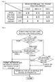
- Fig. 4 is a table for determining the in-vehicle devices 14 to be restricted in accordance with volumes of the high voltage battery electric power amount and the drive motor electric power required amount.
- the first action load restriction processing is executed when it is determined that the SOC state of the high voltage battery 11 is not less than 20% and less than 80% in Step S10 of Fig. 3 .
- the controller 17 respectively classifies the high voltage battery electric power amount calculated from the SOC state of the high voltage battery 11 into three levels of "high”, “medium”, and “low", and the drive motor electric power required amount into three levels of "large”, “medium”, and "small”.
- the controller 17 regards the high voltage battery electric power amount when the SOC state of the high voltage battery 11 is not less than 70% and less than 80% as the "high” level, the high voltage battery electric power amount when the SOC state of the high voltage battery 11 is not less than 40% and less than 70% as the “medium” level, and the high voltage battery electric power amount when the SOC state of the high voltage battery 11 is not less than 20% and less than 40% as the "low” level.
- the controller 17 regards the drive motor electric power required amount not less than 50% of rated electric power of the high voltage battery 11 as the "large” level, the drive motor electric power required amount not less than 20% and less than 50% of the rated electric power as the "medium level”, and the drive motor electric power required amount less than 20% of the rated electric power as the "small” level.
- the controller 17 supplies the electric power only to the in-vehicle devices 14A of the priority A and the in-vehicle devices 14B of the priority B irrespective of the drive motor electric power required amount, so as to only actuate the in-vehicle devices 14A of the priority A and the in-vehicle devices 14B of the priority B.
- the controller 17 restricts supply of the electric power to the in-vehicle devices 14C of the priority C.
- the controller 17 When the high voltage battery electric power amount is at the “medium” level and the drive motor electric power required amount is at the “medium” or “small” level, or when the high voltage battery electric power amount is at the “low” level and the drive motor electric power required amount is at the “small” level, the controller 17 also only actuates the in-vehicle devices 14A of the priority A and the in-vehicle devices 14B of the priority B.
- the controller 17 supplies the electric power only to the in-vehicle devices 14A of the priority A, so as to only actuate the in-vehicle devices 14A of the priority A. In other words, the controller 17 restricts the supply of the electric power to the in-vehicle devices 14B and 14C of the priority B and C.
- Fig. 5 is a flowchart of the first action load restriction processing of executing processing for restricting the actions based on the table of Fig. 4 .
- Step S41 the controller 17 determines to which level of "high”, “medium”, or “low” the high voltage battery electric power amount belongs.
- Step S41 When it is determined that the high voltage battery electric power amount is at the "high" level in Step S41, the flow proceeds to Step S44.
- Step S41 the flow proceeds to Step S42, and the controller 17 determines at which level of "medium” or "small”, or “large” the drive motor electric power required amount is.
- Step S42 When it is determined that the drive motor electric power required amount is at the "medium” or “small” level in Step S42, the flow proceeds to Step S44, and when it is determined that the drive motor electric power required amount is at the "large” level, the flow proceeds to Step S45.
- Step S41 It is determined that the high voltage battery electric power amount is at the "low” level in Step S41, the flow proceeds to Step S43, and the controller 17 determines at which level of "small", or “large” or “medium” the drive motor electric power required amount is.
- Step S43 When it is determined that the drive motor electric power required amount is at the "small” level in Step S43, the flow proceeds to Step S44, and when it is determined that the drive motor electric power required amount is at the "large” or “medium” level, the flow proceeds to Step S45.
- Step S44 the controller 17 permits the actions of the in-vehicle devices 14 of the priority B or higher. That is, the controller 17 supplies the electric power only to the in-vehicle devices 14A and the in-vehicle devices 14B, so as to only actuate the in-vehicle devices 14A and the in-vehicle devices 14B.
- Step S45 the controller 17 permits the actions of the in-vehicle devices 14 of the priority A. That is, the controller 17 supplies the electric power only to the in-vehicle devices 14A, so as to only actuate the in-vehicle devices 14A.
- Step S44 or S45 the first action load restriction processing is finished, and the flow returns to the first power supply control processing of Fig. 3 .
- the first action load restriction processing corresponding to the table of Fig. 4 can be executed.
- the table of Fig. 4 is referred with the high voltage battery electric power amount and the drive motor electric power required amount at the present moment, so as to determine which in-vehicle devices 14 are restricted.
- the controller 17 determines which in-vehicle devices 14 are restricted based on a calculation result using the high voltage battery electric power amount and the drive motor electric power required amount.
- the controller 17 determines whether only the in-vehicle devices 14A of the priority A are actuated or only the in-vehicle devices 14A of the priority A and the in-vehicle devices 14B of the priority B are actuated in accordance with the calculation result of the following expression (2).
- Lvalue 1 ⁇ high voltage battery electric power amount - m ⁇ drive motor electric power required amount wherein 1, m are positive constant numbers. "1 ⁇ (high voltage battery electric power amount)” is always larger than “m ⁇ (drive motor electric power required amount)”. Therefore, Lvalue is always a positive value.
- the controller 17 calculates Lvalue of the expression (2), only actuates the in-vehicle devices 14A and the in-vehicle devices 14B when Lvalue is larger than a threshold value X (Lvalue > X), and only actuates the in-vehicle devices 14A when Lvalue is not larger than the threshold value X (Lvalue ⁇ X).
- Lvalue is within a range from 0 to 100.
- a threshold value of the high voltage battery electric power amount is 70%
- a threshold value of the drive motor electric power required amount is 50%.
- the ground for this is not to use the threshold value of the electric power amount to the upmost limit but to leave some flexibility. That is, the drive motor electric power required amount is within a range from 0 to 50.
- Step S18 of Fig. 3 will be described with reference to Figs. 6 and 7 .
- the actions of part of the in-vehicle devices 14A to 14C are restricted in accordance with the high voltage battery electric power amount.
- Fig. 6 is a table for determining the in-vehicle devices 14 to be restricted in accordance with the high voltage battery electric power amount. "Medium”, “low”, “A”, and “B” in Fig. 6 indicate the same as Fig. 4 .
- the second action load restriction processing is executed when the temperature of the high voltage battery 11 is higher than 0°C and when the SOC state of the high voltage battery 11 is less than 70%.
- the electric power that the high voltage battery 11 is able to output is increased.
- the controller 17 supplies the electric power to the in-vehicle devices 14A of the priority A and the in-vehicle devices 14B of the priority B, so as to only actuate the in-vehicle devices 14A of the priority A and the in-vehicle devices 14B of the priority B. In other words, the controller 17 restricts the supply of the electric power only to the in-vehicle devices 14C of the priority C.
- the controller 17 supplies the electric power only to the in-vehicle devices 14A of the priority A, so as to only actuate the in-vehicle devices 14A of the priority A. In other words, the controller 17 restricts the supply of the electric power to the in-vehicle devices 14B and 14C of the priority B and C.
- Fig. 7 is a flowchart of the second action load restriction processing based on the table of Fig. 6 .
- Step S 61 the controller 17 determines to which level of “medium” or “low” the high voltage battery electric power amount calculated from the SOC state of the high voltage battery 11 belongs.
- Step S61 When it is determined that the high voltage battery electric power amount is at the "medium” level in Step S61, the flow proceeds to Step S62, and the controller 17 permits the actions of the in-vehicle devices 14 of the priority B or higher. That is, the controller 17 supplies the electric power to the in-vehicle devices 14A and the in-vehicle devices 14B, so as to actuate the in-vehicle devices 14A and the in-vehicle devices 14B.
- Step S61 When it is determined that the high voltage battery electric power amount is at the "low” level in Step S61, the flow proceeds to Step S63, and the controller 17 permits the actions of the in-vehicle devices 14 of the priority A. That is, the controller 17 only supplies the electric power to the in-vehicle devices 14A, so as to only actuate the in-vehicle devices 14A.
- Steps S62 or S63 the second action load restriction processing is finished, and the flow returns to the first power supply control processing of Fig. 3 .
- the controller 17 preferentially drives the in-vehicle devices 14A of the priority A essential to the safe vehicle actions in accordance with the high voltage battery electric power amount and the drive motor electric power required amount.
- the high voltage battery electric power amount is low, the output electric power of the high voltage battery 11 can be suppressed. Therefore, the life of the high voltage battery can be extended while ensuring minimum electric power required for the vehicle actions.
- the actions of part of the in-vehicle devices 14 are restricted with using two parameters of the high voltage battery electric power amount and the drive motor electric power required amount, so that the output electric power of the high voltage battery 11 is suppressed.
- the action loads are restricted also in consideration with the SOC state of the low voltage battery 15 and an electric power amount that the low voltage battery 15 is able to output, the electric power amount being calculated by the above SOC state (hereinafter, appropriately called as the low voltage battery electric power amount) in addition to the two parameters of the high voltage battery electric power amount and the drive motor electric power required amount.
- Fig. 8 is a flowchart of the second power supply control processing by the power supply system 1.
- the second power supply control processing of Fig. 8 includes processing from Steps S81 to S100, and Steps S81 to S100 respectively correspond to Steps S1 to S20 of Fig. 3 .
- Steps S81 and S93 are different from Steps S1 and S13 of Fig. 3 .
- Step S81 the controller 17 acquires the SOC states of the high voltage battery 11 and the low voltage battery 15.
- the controller 17 calculates the high voltage battery electric power amount from the SOC state of the high voltage battery 11, and also calculates the low voltage battery electric power amount from the SOC state of the low voltage battery 15. It should be noted that the SOC state of the low voltage battery 15 may be indirectly acquired from the ECU for managing the low voltage battery 15 as well as the SOC state of the high voltage battery 11.
- Step S93 the controller 17 executes the first action load restriction processing of restricting the actions of the action loads in accordance with the high voltage battery electric power amount, the low voltage battery electric power amount, and the drive motor electric power required amount.
- the controller determines of which in-vehicle devices 14 the actions are restricted based on a calculation result using an arithmetic expression similar to the expression (2) in the above first power supply control processing.
- the controller 17 determines whether only the in-vehicle devices 14A of the priority A are actuated or the in-vehicle devices 14A of the priority A and the in-vehicle devices 14B of the priority B are actuated in accordance with the calculation result of the following expression (3).
- the controller 17 calculates Lvalue of the expression (3), actuates the in-vehicle devices 14A and the in-vehicle devices 14B when Lvalue is larger than the threshold value X (Lvalue > X), and only actuates the in-vehicle devices 14A when Lvalue is not larger than the threshold value X (Lvalue ⁇ X).
- the actions of part of the in-vehicle devices 14A to 14C serving as the action loads are restricted with using three parameters of the high voltage battery electric power amount, the low voltage battery electric power amount, and the drive motor electric power required amount, so that the output electric power of the high voltage battery 11 can be suppressed.
- the actions of part of the in-vehicle devices 14 are restricted with using the three parameters of the high voltage battery electric power amount, the low voltage battery electric power amount, and the drive motor electric power required amount, so that the output electric power of the high voltage battery 11 is suppressed.
- the action loads are restricted also in consideration with a total electric power amount at the time of actuating the in-vehicle devices 14A of the priority A and the in-vehicle devices 14B of the priority B in addition to the three parameters.
- the total electric power amount at the time of actuating the in-vehicle devices 14A of the priority A and the in-vehicle devices 14B of the priority B is called as the DC/DC load electric power required amount.
- Fig. 9 is a flowchart of the third power supply control processing by the power supply system 1.
- the third power supply control processing of Fig. 9 includes processing from Steps S121 to S140, and Steps S121 to S140 respectively correspond to Steps S81 to S100 of Fig. 8 .
- Steps S132 and S133 are different from Steps S92 and S93 of Fig. 8 .
- Steps S132 and S133 will be described, and description of the remaining steps will be omitted.
- Step S132 the controller 17 acquires the drive motor electric power required amount from the drive motor 16 and also acquires the DC/DC load electric power required amount from the ECU included in the in-vehicle devices 14A.
- Step S133 the controller 17 executes the first action load restriction processing of restricting the actions of the action loads in accordance with the high voltage battery electric power amount, the low voltage battery electric power amount, the drive motor electric power required amount, and the DC/DC load electric power required amount.
- the controller determines of which in-vehicle devices 14 the actions are restricted based on a calculation result using an arithmetic expression similar to the expression (3) in the above second power supply control processing.
- the controller 17 determines whether only the in-vehicle devices 14A of the priority A are actuated or the in-vehicle devices 14A of the priority A and the in-vehicle devices 14B of the priority B are actuated in accordance with the calculation result of the following expression (4).
- Lvalue 1 ⁇ high voltage battery electric power amount + low voltage battery electric power amount - m ⁇ drive motor electric power required amount + DC / DC load electric power required amount
- the controller 17 calculates Lvalue of the expression (4), actuates the in-vehicle devices 14A and the in-vehicle devices 14B when Lvalue is larger than the threshold value X (Lvalue > X), and only actuates the in-vehicle devices 14A when Lvalue is not larger than the threshold value X (Lvalue ⁇ X).
- the actions of part of the in-vehicle devices 14A to 14C serving as the action loads are restricted with using four parameters of the high voltage battery electric power amount, the low voltage battery electric power amount, the drive motor electric power required amount, and the DC/DC load electric power required amount, so that the output electric power of the high voltage battery 11 can be suppressed.
- the power supply system 1 classifies the in-vehicle devices into the in-vehicle devices 14 essential to the safe vehicle actions and other in-vehicle devices 14, and preferentially drives the in-vehicle devices 14A of the priority A essential to the safe vehicle actions in accordance with the high voltage battery electric power amount, the drive motor electric power required amount, and the like.
- the output electric power can be suppressed corresponding to a decrease in the electric power that the high voltage battery 11 is able to output when the temperature of the high voltage battery 11 becomes a low temperature.
- the life of the high voltage battery can be extended while ensuring the minimum electric power required for the vehicle actions.
- the present invention can be applied to a power supply system for controlling a power supply of a battery in a vehicle using the battery as part of a power source or as the entire power source such as an electric vehicle and a hybrid vehicle.
- a series of the above processing can be executed by hardware or by software.
- a program of the software is provided and installed on a computer built into dedicated hardware (such as a CPU (Central Processing Unit), an ECU, a BMU (Battery Management Unit)), or for example a general-purpose personal computer capable of executing various functions with various programs installed, via a program recording medium, or a wired or wireless transmission medium such as local area network, internet, and digital satellite broadcasting.
- a program recording medium such as a program recording medium, or a wired or wireless transmission medium such as local area network, internet, and digital satellite broadcasting.
- Fig. 10 is a block diagram showing a configuration example of the hardware of the computer serving as the controller 17 for executing the series of the above processing by the program.
- a CPU Central Processing Unit
- ROM Read Only Memory
- RAM Random Access Memory
- An input and output interface 105 is further connected to the bus 104.
- An input portion 106, an output portion 107, a memory 108, a communication portion 109, and a drive 110 are connected to the input and output interface 105.
- the input portion 106 includes a keyboard, a mouse, a microphone, and the like.
- the output portion 107 includes a display, a speaker, and the like.
- the memory 108 includes a hard disk, a nonvolatile memory, and the like.
- the communication portion 109 includes a network interface and the like.
- the drive 110 drives a removable recording medium 111 such as a magnetic disk, an optical disc, a magnet-optical disc, or a semiconductor memory.
- the CPU 101 loads and executes the program stored in the memory 108 for example to the RAM 103 via the input and output interface 105 and the bus 104, so that the series of the above processing is performed.
- the program executed by the computer can be recorded and provided for example in the removable recording medium 111 serving as a package medium or the like.
- the program can also be provided via the wired or wireless transmission medium such as the local area network, the internet, and the digital satellite broadcasting.
- the removable recording medium 111 is mounted onto the drive 110, so that the program can be installed on the memory 108 via the input and output interface 105.
- the program can be received by the communication portion 109 via the wired or wireless transmission medium and installed on the memory 108.
- the program can be preliminarily installed on the ROM 102 or the memory 108.
- the program executed by the computer may be a program with processing performed in chronological order along the order described in the present specification, or a program with processing performed in parallel or at necessary timing such as when a call is placed.
- system indicates the entire apparatus formed by a plurality of devices.
Landscapes
- Engineering & Computer Science (AREA)
- Power Engineering (AREA)
- Transportation (AREA)
- Mechanical Engineering (AREA)
- Life Sciences & Earth Sciences (AREA)
- Sustainable Development (AREA)
- Sustainable Energy (AREA)
- Electric Propulsion And Braking For Vehicles (AREA)
- Charge And Discharge Circuits For Batteries Or The Like (AREA)
Abstract
Description
- The present invention relates to a power supply system and a power supply control method, particularly to a power supply system capable of extending the life of a high voltage battery while ensuring minimum electric power required for vehicle actions, and a power supply control method.
- In general, it is known that in an environment where an external temperature is low, internal resistance is radically increased and a discharge ability is lowered in a battery (for example, refer to "Discharge Temperature Characteristics" on the website of BAYSUN Co., Ltd. [URL: http://www.baysun.net/lithium/lithium10.html]).
-
Fig. 1 shows discharge characteristics due to a difference in an environmental temperature of a lithium ion battery having nominal capacity of 2,000 mAh (discharge temperature characteristics) disclosed in the above website. The horizontal axis ofFig. 1 indicates discharge capacity, and the vertical axis indicates cell voltage. Referring toFig. 1 , it is found that the internal resistance is radically increased and the discharge ability is lowered with the temperature of 0°C or lower. Therefore, even with a high voltage battery in a hybrid vehicle or the like, in an environment where the external temperature is low such as a cold region, a load is increased due to the increased internal resistance, and electric power to be outputted is reduced due to the lowered voltage of the high voltage battery. When the electric power to be outputted is reduced, the electric power required for units actuated as loads of the high voltage battery cannot be ensured, so that actions of the units are sometimes influenced. Since the load is increased due to the increased internal resistance, the life of the high voltage battery is shortened. - Many of hybrid vehicles and electric vehicles require both high-voltage power for directly driving the vehicles themselves, and low-voltage power for driving various in-vehicle devices. This is because the in-vehicle devices are conventionally designed to be driven by voltage (such as 12 V) of a low voltage battery mounted in the vehicles when mounted on gasoline-powered vehicles or the like, and there is still high demand and need for installing and continuing to use the conventional in-vehicle devices in the electric vehicles or the like.
- In such a way, as a configuration for supplying both the high-voltage power and the low-voltage power in the vehicles, both the high voltage battery and the low voltage battery are generally mounted in the electric vehicles or the like. Further, in order to supplement the electric power to the low voltage battery, there is a known configuration that a DC/DC converter is mounted to convert the voltage, and then the electric power is supplied from the high voltage battery to the low voltage battery.
- In the electric vehicles or the like with such a configuration, as a measure for not unnecessarily shortening the life of the high voltage battery, a technology of starting up a DC/DC converter at low voltage particularly at the time of a low temperature, and then controlling to drive at high voltage, so as to protect the high voltage battery is disclosed (for example, refer to Japanese Patent No.
3566252 - However, with the method of Japanese Patent No.
3566252 3566252 - The present invention has been devised to solve the above problem and an object thereof is to extend the life of a high voltage battery while ensuring minimum electric power required for vehicle actions.
- In accordance with a first aspect of the present invention, a power supply system comprises a first battery for supplying an electric power at a first voltage, a second battery for supplying an electric power at a second voltage lower than the first voltage, a voltage converting unit connected to the first battery and the second battery, and intended to receive an electric current from the first battery, to convert the first voltage of the electric current into the second voltage, and then to supply the electric current to the second battery, a measuring unit for measuring a temperature of the first battery, one or a plurality of first loads driven by the second battery, one or a plurality of second loads driven by the second battery, and a control unit for driving in priority the first loads based on an electric power amount that the first battery is able to output and on an electric power amount required by a drive motor for driving a vehicle, when the temperature of the first battery is not higher than a predetermined temperature.
- In the power supply system according to the first aspect of the present invention, the temperature of the first battery is measured, and when the temperature of the first battery is not higher than the predetermined temperature, the first loads of the first priority among the first and second loads driven by the second battery are driven in priority based on the electric power amount that the first battery is able to output and on the electric power amount required by the drive motor for driving the vehicle.
- Therefore, when the temperature of the first battery is not higher than the predetermined temperature, the supply of the electric power to the second loads is restricted, so that the electric power supplied by the first battery to devices other than the drive motor is suppressed, and the first battery is thus not excessively operated. Thereby, the output electric power of the first battery can be suppressed, so that the life of the first battery can be extended while ensuring the minimum electric power required for the vehicle actions.
- The first battery is for example formed by a battery for supplying the electric power at a voltage such as 144 V, 300 V, and 334 V. The second battery is for example formed by a battery for supplying an electric power at a voltage such as 12 V. The voltage converting unit is for example formed by a DC/DC converter. The measuring unit is for example formed by a temperature sensor The first loads are for example formed by an EPSECU, an engine ECU, and the like. The second loads are for example formed by an air conditioner, audio devices, a navigation device, and the like. The control unit is for example formed by a CPU serving as a controller, an ECU, a BMU, or the like.
- According to an embodiment of the present invention, the control unit may restrict the supply of the electric power to a part of a plurality of loads driven by the first battery other than the drive motor based only on the electric power amount that the first battery is able to output, when the temperature of the first battery is higher than the predetermined temperature.
- Thereby, when the electric power amount that the first battery is able to output is low, the output electric power of the first battery can be suppressed, so that the life of the first battery can be extended while ensuring the minimum electric power required for the vehicle actions.
- According to a further embodiment of the present invention, the control unit may suppress the output voltage of the voltage converting unit in accordance with at least a state of charge of the second battery and a maximum voltage among the drive voltage of a plurality of loads driven by the first battery other than the drive motor.
- Thereby, the consumed electric power due to the plurality of loads can be suppressed.
- According to a second aspect of the present invention, a power supply control method in a power supply system comprising a first battery for supplying an electric power at a first voltage, a second battery for supplying an electric power at a second voltage lower than the first voltage, a voltage converting unit connected to the first battery and the second battery, and intended to receive the electric current from the first battery, to convert the first voltage of the electric current into the second voltage, and then to supply the electric current to the second battery, a measuring unit for measuring a temperature of the first battery, one or a plurality of first loads driven by the second battery, one or a plurality of second loads driven by the second battery, and a control unit for controlling the drive of the first and second loads, wherein the power supply control method includes the step of driving in priority the first loads by the control unit based on an electric power amount that the first battery is able to output and on an electric power amount required by a drive motor for driving a vehicle, when the temperature of the first battery is not higher than a predetermined temperature.
- In the power supply control method according to the second aspect of the present invention, the temperature of the first battery is measured, and when the temperature of the first battery is not higher than the predetermined temperature, the first loads are driven in priority based on the electric power amount that the first battery is able to output and on the electric power amount required by the drive motor for driving the vehicle.
- Therefore, when the temperature of the first battery is not higher than the predetermined temperature, the supply of the electric power to the second loads of the second priority is restricted, so that the electric power supplied by the first battery to devices other than the drive motor is suppressed, and the first battery is thus not excessively operated. Thereby, the output electric power of the first battery is suppressed, so that the life of the first battery can be extended while ensuring the minimum electric power required for the vehicle actions.
- The control unit for executing this step is for example formed by a CPU (Central Processing Unit), an ECU, a BMU (Battery Management Unit), or the like.
- According to this second aspect of the present invention, the life of the high voltage battery can be extended while ensuring the minimum electric power required for the vehicle actions.
-
-
Fig. 1 is a graph showing the discharge temperature characteristics of a battery; -
Fig. 2 is a block diagram showing a configuration example of a power supply system according to an embodiment of the present invention; -
Fig. 3 is a flowchart illustrating a first power supply control processing according to an embodiment of the present invention; -
Fig. 4 is a table relating to a first action load restriction processing ofFig. 3 ; -
Fig. 5 is a flowchart illustrating the first action load restriction processing ofFig. 3 ; -
Fig. 6 is a table relating to a second action load restriction processing ofFig. 3 ; -
Fig. 7 is a flowchart illustrating the second action load restriction processing ofFig. 3 ; -
Fig. 8 is a flowchart illustrating a second power supply control processing according to an embodiment of the present invention; -
Fig. 9 is a flowchart illustrating a third power supply control processing according to an embodiment of the present invention; and -
Fig. 10 is a block diagram showing a configuration example of a computer according to an embodiment of the present invention. -
Fig. 2 is a block diagram showing a configuration example of a power supply system according to an embodiment of the present invention. - A
power supply system 1 ofFig. 2 is a system for controlling a power supply of an electric vehicle running by electric power stored in a battery. It should be noted that inFig. 2 , an electric power supply line is shown by a double line, and a control line is shown by one solid line. - The
power supply system 1 is formed by ahigh voltage battery 11, atemperature sensor 12, a DC/DC converter 13, an in-vehicle device group 14', alow voltage battery 15, adrive motor 16, and acontroller 17. - The
high voltage battery 11 is a major power supply of the electric vehicle and supplies (discharges) the stored electric power if necessary. Thehigh voltage battery 11 may adopt output voltage of for example 144V, 300V, 334V, or the like. - The
temperature sensor 12 is installed in the vicinity of thehigh voltage battery 11, measures a temperature of thehigh voltage battery 11, and outputs the temperature to thecontroller 17. It should be noted that although the temperature of thehigh voltage battery 11 is directly measured with using thetemperature sensor 12 in the present embodiment, thetemperature sensor 12 may be attached to another place where thetemperature sensor 12 is more easily installed, so that the temperature of thehigh voltage battery 11 is indirectly measured. A method of indirectly estimating the temperature of thehigh voltage battery 11 by predetermined calculation without using the temperature sensor is also available. - The DC/
DC converter 13 is connected to thehigh voltage battery 11 and thelow voltage battery 15, receives an electric current from thehigh voltage battery 11, converts first voltage serving as output voltage of thehigh voltage battery 11 into second voltage serving as output voltage of thelow voltage battery 15, and then supplies the electric current to thelow voltage battery 15. That is, the DC/DC converter 13 converts the electric power supplied from thehigh voltage battery 11 into the electric power to be supplied to in-vehicle devices 14 actuated at low voltage. Since many of the current in-vehicle devices 14 are driven at 12 V, the DC/DC converter 13 converts the voltage into power supply voltage of 12 V in the present embodiment. However, the voltage to be converted is not limited to 12 V but can be appropriately set in accordance with drive voltage of the in-vehicle devices 14. The electric power with the voltage converted by the DC/DC converter 13 is supplied to thelow voltage battery 15 and the in-vehicle device group 14'. - The in-vehicle device group 14' is a collection of the plural in-
vehicle devices 14 actuated at the power supply voltage of 12 V. In the present embodiment, the in-vehicle devices 14 belonging to the in-vehicle device group 14' are classified into in-vehicle devices 14A, in-vehicle devices 14B, and in-vehicle devices 14C in accordance with priority of actions thereof. The in-vehicle devices 14A are of the highest priority (priority A) and serve as devices essential to safe vehicle actions. The in-vehicle devices 14A correspond to for example an EPSECU (Electric Power Steering ECU), an engine ECU, and the like. The in-vehicle devices 14B are of the second highest priority (priority B) and serve as devices necessary for comfortable vehicle actions. The in-vehicle devices 14B correspond to for example an air conditioner (so-called air-con) and the like. The in-vehicle devices 14C are of the lowest priority (priority C) and serve as devices least influential to a user other than the in-vehicle devices claim 1 correspond to the in-vehicle devices 14A in the present embodiment, and second loads ofclaim 1 correspond to the in-vehicle devices 14B and 14C in the present embodiment. The priority of the second loads is further divided into two, and thus the in-vehicle devices are divided into the in-vehicle devices 14B and 14C in accordance with the priority. However, the priority can be further divided if necessary. - The in-
vehicle devices 14A to 14C are action loads of thehigh voltage battery 11 for receiving the electric power supplied via the DC/DC converter 13 or thelow voltage battery 15, and performing predetermined actions. - The
low voltage battery 15 stores the electric power supplied from the DC/DC converter 13 and also supplies the electric power to the in-vehicle devices 14A to 14C. - The
drive motor 16 is a maximum load (action load) actuated by thehigh voltage battery 11 and a motor for driving the electric vehicle. Thedrive motor 16 corresponds to an engine of a vehicle driven by gasoline as fuel. Thedrive motor 16 has generator functions of generating the electric power and charging thehigh voltage battery 11 at the time of braking the vehicle, and collecting regenerative energy. Therefore, thedrive motor 16 will also be called as thedrive motor generator 16 hereinafter. - The
controller 17 controls thedrive motor 16. For example, thecontroller 17 controls an output of thedrive motor 16, and measures a generation amount of the drive motor (generator) 16. Thecontroller 17 manages output electric power of thehigh voltage battery 11 and the DC/DC converter 13, and controls to restrict the actions of part of the in-vehicle device group 14' if necessary. It should be noted that thecontroller 17 can acquire various information from the ECU belonging to the in-vehicle devices 14A for controlling units if necessary. - In the
power supply system 1 formed as above, when the temperature of thehigh voltage battery 11 becomes a low temperature (such as 0°C or lower), the voltage of the high voltage battery is lowered, so that the electric power to be outputted is reduced. In this case, thecontroller 17 of thepower supply system 1 performs power supply control processing of restricting the actions of part of the in-vehicle device group 14' in accordance with a SOC (state of charge) state of thehigh voltage battery 11 and an electric power required amount of thedrive motor 16. - Hereinafter, the power supply control processing performed by the
power supply system 1 will be described with reference to the drawings. - Firstly, first power supply control processing will be described with reference to a flowchart of
Fig. 3 . - In the first power supply control processing, an electric power amount that the
high voltage battery 11 is able to output (hereinafter, appropriately called as the high voltage battery electric power amount) is calculated from the SOC state of thehigh voltage battery 11, and the actions of part of the in-vehicle device group 14' serving as loads of the DC/DC converter 13 are restricted in accordance with the high voltage battery electric power amount and the electric power required amount of the drive motor 16 (hereinafter, appropriately called as the drive motor electric power required amount). - Firstly, in Step S1, the
controller 17 acquires the SOC (state of charge) state from thehigh voltage battery 11. Thecontroller 17 then calculates the high voltage battery electric power amount from the acquired SOC state of thehigh voltage battery 11. It should be noted that an electric power amount in a fully charged state of thehigh voltage battery 11 is already known. The SOC state of thehigh voltage battery 11 may be indirectly acquired from the ECU for managing thehigh voltage battery 11. - In Step S2, the
controller 17 acquires the temperature of thehigh voltage battery 11 by acquiring a sensor value of thetemperature sensor 12. - In Step S3, the
controller 17 determines whether or not the temperature of thehigh voltage battery 11 is not higher than a predetermined threshold value. The threshold value is 0°C. That is, in Step S3, thecontroller 17 determines whether or not the temperature of thehigh voltage battery 11 is not higher than 0°C. It should be noted that the temperature serving as the threshold value in Step S3 can be appropriately determined in accordance with action setting. - When it is determined that the temperature of the
high voltage battery 11 is not higher than 0°C in Step S3, the flow proceeds to Step S4, and thecontroller 17 measures the generation amount of thedrive motor generator 16, and in Step S5, measures the output electric power of the DC/DC converter 13. - In Step S6, the
controller 17 determines whether or not the generation amount of thedrive motor generator 16 is larger than the output electric power of the DC/DC converter 13. - When it is determined that the generation amount of the
drive motor generator 16 is larger than the output electric power of the DC/DC converter 13 in Step S6, the flow proceeds to Step S7, and thecontroller 17 sets an internal generation favorable flag to "1". The generation favorable flag "1" indicates that the electric power is sufficiently generated, and a generation favorable flag "0" indicates that the electric power is not sufficiently generated. - Meanwhile, when it is determined that the generation amount of the
drive motor generator 16 is not larger than the output electric power of the DC/DC converter 13 in Step S6, the flow proceeds to Step S8, and thecontroller 17 sets the internal generation favorable flag to "0". In Step S9, thecontroller 17 increases generation torque of thedrive motor generator 16. - After Step S7 or S9, in Step S10, the
controller 17 determines in which range of less than 20%, not less than 20% to less than 80%, or not less than 80% the SOC state of thehigh voltage battery 11 is included. - When it is determined that the SOC state of the
high voltage battery 11 is less than 20% in Step S10, the flow proceeds to Step S11, and thecontroller 17 generates an alarm indicating that the high voltage battery electric power amount is in short with using a voice generating device, an indicator, or the like (not shown). - Meanwhile, when it is determined that the SOC state of the
high voltage battery 11 is not less than 20% and less than 80% in Step S10, the flow proceeds to Step S12, and thecontroller 17 acquires the drive motor electric power required amount from thedrive motor 16. It should be noted that the drive motor electric power required amount may be acquired from the ECU for controlling thedrive motor 16. - In Step S13, the
controller 17 executes the first action load restriction processing of restricting the actions of part of the in-vehicle devices 14A to 14C serving as the action loads in accordance with the high voltage battery electric power amount calculated from the SOC state of thehigh voltage battery 11 and the acquired drive motor electric power required amount. Details of this processing will be described later with reference toFigs. 4 and 5 . - Meanwhile, when it is determined that the SOC state of the
high voltage battery 11 is not less than 80% in Step S10, the actions of the in-vehicle devices 14A to 14C are not particularly restricted, and the flow proceeds to Step S14. - In Step S14, the
controller 17 determines whether or not the generation favorable flag is "1" . - When it is determined that the generation favorable flag is "1" in Step S14, the flow proceeds to Step S15, and the
controller 17 sets the DC/DC converter 13 so that the DC/DC output voltage serves as an normal output. - Meanwhile, when it is determined that the generation favorable flag is "0" in
Step S 14, the flow proceeds to StepS 16, and thecontroller 17 sets the DC/DC converter 13 so that the DC/DC output voltage is suppressed. - How to determine the DC/DC output voltage after suppression when the
controller 17 suppresses the DC/DC output voltage will be described. - The
controller 17 acquires a SOC state of thelow voltage battery 15 and DC/DC load required voltage Vreq from a predetermined ECU. The DC/DC load required voltage Vreq is maximum voltage among drive voltage of the in-vehicle devices 14 to be actuated. - The
controller 17 can determine DC/DC output voltage Vout after the suppression as follows with using the SOC state of thelow voltage battery 15, the DC/DC load required voltage Vreq, and a shortage amount of the generation amount of themotor generator 16. -

wherein K, k, p are predetermined constant numbers. P indicates a generation target value, and Pgen indicates the generation amount of themotor generator 16. - That is, the DC/DC output voltage Vout after the suppression can be calculated as the sum determined by adding the constant number K to a result of multiplying an absolute value of the generation target value P and the motor generator generation amount Pgen multiplied by p, and the SOC state of the
low voltage battery 15 multiplied by k. However, when the calculated DC/DC output voltage Vout is smaller than the DC/DC load required voltage Vreq, the DC/DC load required voltage Vreq serves as the DC/DC output voltage Vout. - In such a way, the
controller 17 suppresses the DC/DC output voltage with using the SOC state of thelow voltage battery 15, the DC/DC load required voltage Vreq, and the shortage amount of the generation amount of themotor generator 16. Thus, consumed electric power by the in-vehicle devices 14 can be suppressed. - Meanwhile, when it is determined that the temperature of the
high voltage battery 11 is higher than 0°C in Step S3, the flow proceeds to Step S17, and thecontroller 17 determines whether or not the SOC state of thehigh voltage battery 11 is not less than a predetermined threshold value. The threshold value is for example 70%. Therefore, in Step S17, thecontroller 17 determines whether or not the SOC state of thehigh voltage battery 11 is not less than 70%. - When it is determined that the SOC state of the
high voltage battery 11 is not less than 70% inStep S 17, the flow proceeds to Step S18, and thecontroller 17 executes second action load restriction processing of restricting the actions of the action loads in accordance with the high voltage battery electric power amount calculated from the SOC state of thehigh voltage battery 11. Details of this processing will be described later with reference toFigs. 6 and 7 . - Meanwhile, when it is determined that the SOC state of the
high voltage battery 11 is not less than 70% in Step S17, the actions of the action loads are not particularly restricted, and the flow proceeds to StepS 19. - After the action load restriction processing of restricting the actions of the action loads in accordance with the high voltage battery electric power amount calculated from the SOC state of the
high voltage battery 11 is performed if necessary by the above processing in Steps S3 to S18, thecontroller 17 determines whether or not the DC/DC converter 13 is turned off in Step S19. - When it is determined that the DC/
DC converter 13 is turned off in Step S19, in other words, when there is no output from the DC/DC converter 13, thecontroller 17 turns on the DC/DC converter 13 in Step S20, and finishes the processing. Meanwhile, when the DC/DC converter 13 is turned on inStep S 19, the processing is finished straightaway. - The above first power supply control processing is continuously executed irrespective of the time such as idling and running of the vehicle. That is, the above processing in Step S1 to S20 is repeatedly executed.
- Next, the first action load restriction processing in Step S13 of
Fig. 3 will be described with reference toFigs. 4 and 5 . - In the first action load restriction processing, the actions of part of the in-
vehicle devices 14A to 14C are restricted in accordance with the high voltage battery electric power amount and the drive motor electric power required amount. -
Fig. 4 is a table for determining the in-vehicle devices 14 to be restricted in accordance with volumes of the high voltage battery electric power amount and the drive motor electric power required amount. - The first action load restriction processing is executed when it is determined that the SOC state of the
high voltage battery 11 is not less than 20% and less than 80% in Step S10 ofFig. 3 . Thecontroller 17 respectively classifies the high voltage battery electric power amount calculated from the SOC state of thehigh voltage battery 11 into three levels of "high", "medium", and "low", and the drive motor electric power required amount into three levels of "large", "medium", and "small". For example, thecontroller 17 regards the high voltage battery electric power amount when the SOC state of thehigh voltage battery 11 is not less than 70% and less than 80% as the "high" level, the high voltage battery electric power amount when the SOC state of thehigh voltage battery 11 is not less than 40% and less than 70% as the "medium" level, and the high voltage battery electric power amount when the SOC state of thehigh voltage battery 11 is not less than 20% and less than 40% as the "low" level. Thecontroller 17 regards the drive motor electric power required amount not less than 50% of rated electric power of thehigh voltage battery 11 as the "large" level, the drive motor electric power required amount not less than 20% and less than 50% of the rated electric power as the "medium level", and the drive motor electric power required amount less than 20% of the rated electric power as the "small" level. - It should be noted that in the table of
Fig. 4 , "A" indicates that the in-vehicle devices 14A of the priority A are actuated, and "B" indicates that the in-vehicle devices 14B of the priority B are actuated. - Therefore, according to the table of
Fig. 4 , when the high voltage battery electric power amount is at the "high" level, thecontroller 17 supplies the electric power only to the in-vehicle devices 14A of the priority A and the in-vehicle devices 14B of the priority B irrespective of the drive motor electric power required amount, so as to only actuate the in-vehicle devices 14A of the priority A and the in-vehicle devices 14B of the priority B. In other words, thecontroller 17 restricts supply of the electric power to the in-vehicle devices 14C of the priority C. - When the high voltage battery electric power amount is at the "medium" level and the drive motor electric power required amount is at the "medium" or "small" level, or when the high voltage battery electric power amount is at the "low" level and the drive motor electric power required amount is at the "small" level, the
controller 17 also only actuates the in-vehicle devices 14A of the priority A and the in-vehicle devices 14B of the priority B. - Meanwhile, when the high voltage battery electric power amount is at the "medium" level and the drive motor electric power required amount is at the "large" level, or when the high voltage battery electric power amount is at the "low" level and the drive motor electric power required amount is at the "large" or "medium" level, the
controller 17 supplies the electric power only to the in-vehicle devices 14A of the priority A, so as to only actuate the in-vehicle devices 14A of the priority A. In other words, thecontroller 17 restricts the supply of the electric power to the in-vehicle devices 14B and 14C of the priority B and C. -
Fig. 5 is a flowchart of the first action load restriction processing of executing processing for restricting the actions based on the table ofFig. 4 . - In Step S41, the
controller 17 determines to which level of "high", "medium", or "low" the high voltage battery electric power amount belongs. - When it is determined that the high voltage battery electric power amount is at the "high" level in Step S41, the flow proceeds to Step S44.
- Meanwhile, it is determined that the high voltage battery electric power amount is at the "medium" level in Step S41, the flow proceeds to Step S42, and the
controller 17 determines at which level of "medium" or "small", or "large" the drive motor electric power required amount is. - When it is determined that the drive motor electric power required amount is at the "medium" or "small" level in Step S42, the flow proceeds to Step S44, and when it is determined that the drive motor electric power required amount is at the "large" level, the flow proceeds to Step S45.
- It is determined that the high voltage battery electric power amount is at the "low" level in Step S41, the flow proceeds to Step S43, and the
controller 17 determines at which level of "small", or "large" or "medium" the drive motor electric power required amount is. - When it is determined that the drive motor electric power required amount is at the "small" level in Step S43, the flow proceeds to Step S44, and when it is determined that the drive motor electric power required amount is at the "large" or "medium" level, the flow proceeds to Step S45.
- In Step S44, the
controller 17 permits the actions of the in-vehicle devices 14 of the priority B or higher. That is, thecontroller 17 supplies the electric power only to the in-vehicle devices 14A and the in-vehicle devices 14B, so as to only actuate the in-vehicle devices 14A and the in-vehicle devices 14B. - In Step S45, the
controller 17 permits the actions of the in-vehicle devices 14 of the priority A. That is, thecontroller 17 supplies the electric power only to the in-vehicle devices 14A, so as to only actuate the in-vehicle devices 14A. - By the processing in Step S44 or S45, the first action load restriction processing is finished, and the flow returns to the first power supply control processing of
Fig. 3 . - By the above processing, the first action load restriction processing corresponding to the table of
Fig. 4 can be executed. - Next, another example of the first action load restriction processing will be described.
- In the first action load restriction processing of
Fig. 5 , the table ofFig. 4 is referred with the high voltage battery electric power amount and the drive motor electric power required amount at the present moment, so as to determine which in-vehicle devices 14 are restricted. - Meanwhile, in another example of the first action load restriction processing described below, the
controller 17 determines which in-vehicle devices 14 are restricted based on a calculation result using the high voltage battery electric power amount and the drive motor electric power required amount. - Specifically, the
controller 17 determines whether only the in-vehicle devices 14A of the priority A are actuated or only the in-vehicle devices 14A of the priority A and the in-vehicle devices 14B of the priority B are actuated in accordance with the calculation result of the following expression (2). -

wherein 1, m are positive constant numbers. "1 × (high voltage battery electric power amount)" is always larger than "m × (drive motor electric power required amount)". Therefore, Lvalue is always a positive value. - The
controller 17 calculates Lvalue of the expression (2), only actuates the in-vehicle devices 14A and the in-vehicle devices 14B when Lvalue is larger than a threshold value X (Lvalue > X), and only actuates the in-vehicle devices 14A when Lvalue is not larger than the threshold value X (Lvalue ≤ X). - For example, in the expression (2), Lvalue is within a range from 0 to 100. With
Fig. 1 , the voltage starts lowering drastically from a point over 70% of rated capacity. Thus, when a threshold value of the high voltage battery electric power amount is 70%, a threshold value of the drive motor electric power required amount is 50%. The ground for this is not to use the threshold value of the electric power amount to the upmost limit but to leave some flexibility. That is, the drive motor electric power required amount is within a range from 0 to 50. The threshold value X is 20 (X = 20) from a difference (70-50) between the high voltage battery electric power amount at degrees below freezing serving as 70% of the rated capacity (70), and the threshold value of the drive motor electric power required amount when maximum torque is required serving as 50% (50). - It should be noted that in order to have the value of (1 × high voltage battery electric power amount) within the range from 0 to 100, and have the value of (m × drive motor electric power required amount) within the range from 0 to 50, for example when Pb denotes a rated value of the high voltage battery electric power amount, and Tmax denotes a rated value of the drive motor electric power required amount, "1= 100 / Pb" and "m = 50 / Tmax" are available.
- Next, the second action load restriction processing in Step S18 of
Fig. 3 will be described with reference toFigs. 6 and 7 . - In the second action load restriction processing, the actions of part of the in-
vehicle devices 14A to 14C are restricted in accordance with the high voltage battery electric power amount. -
Fig. 6 is a table for determining the in-vehicle devices 14 to be restricted in accordance with the high voltage battery electric power amount. "Medium", "low", "A", and "B" inFig. 6 indicate the same asFig. 4 . - As described above with reference to
Fig. 3 , the second action load restriction processing is executed when the temperature of thehigh voltage battery 11 is higher than 0°C and when the SOC state of thehigh voltage battery 11 is less than 70%. In a state that the temperature of thehigh voltage battery 11 is not lower than 0°C, as described above with reference toFig. 1 , the electric power that thehigh voltage battery 11 is able to output is increased. - When the high voltage battery electric power amount at the present moment is at the "medium" level, the
controller 17 supplies the electric power to the in-vehicle devices 14A of the priority A and the in-vehicle devices 14B of the priority B, so as to only actuate the in-vehicle devices 14A of the priority A and the in-vehicle devices 14B of the priority B. In other words, thecontroller 17 restricts the supply of the electric power only to the in-vehicle devices 14C of the priority C. - Meanwhile, when the high voltage battery electric power amount at the present time is at the "low" level, the
controller 17 supplies the electric power only to the in-vehicle devices 14A of the priority A, so as to only actuate the in-vehicle devices 14A of the priority A. In other words, thecontroller 17 restricts the supply of the electric power to the in-vehicle devices 14B and 14C of the priority B and C. -
Fig. 7 is a flowchart of the second action load restriction processing based on the table ofFig. 6 . - In
Step S 61, thecontroller 17 determines to which level of "medium" or "low" the high voltage battery electric power amount calculated from the SOC state of thehigh voltage battery 11 belongs. - When it is determined that the high voltage battery electric power amount is at the "medium" level in Step S61, the flow proceeds to Step S62, and the
controller 17 permits the actions of the in-vehicle devices 14 of the priority B or higher. That is, thecontroller 17 supplies the electric power to the in-vehicle devices 14A and the in-vehicle devices 14B, so as to actuate the in-vehicle devices 14A and the in-vehicle devices 14B. - When it is determined that the high voltage battery electric power amount is at the "low" level in Step S61, the flow proceeds to Step S63, and the
controller 17 permits the actions of the in-vehicle devices 14 of the priority A. That is, thecontroller 17 only supplies the electric power to the in-vehicle devices 14A, so as to only actuate the in-vehicle devices 14A. - By the processing in Steps S62 or S63, the second action load restriction processing is finished, and the flow returns to the first power supply control processing of
Fig. 3 . - According to the first power supply control processing described above, when the temperature of the
high voltage battery 11 becomes a low temperature (such as 0°C or lower), thecontroller 17 preferentially drives the in-vehicle devices 14A of the priority A essential to the safe vehicle actions in accordance with the high voltage battery electric power amount and the drive motor electric power required amount. Thereby, when the high voltage battery electric power amount is low, the output electric power of thehigh voltage battery 11 can be suppressed. Therefore, the life of the high voltage battery can be extended while ensuring minimum electric power required for the vehicle actions. - Next, second power supply control processing serving as a second embodiment of the present invention will be described.
- In the first power supply control processing, the actions of part of the in-
vehicle devices 14 are restricted with using two parameters of the high voltage battery electric power amount and the drive motor electric power required amount, so that the output electric power of thehigh voltage battery 11 is suppressed. - In the second power supply control processing, the action loads are restricted also in consideration with the SOC state of the
low voltage battery 15 and an electric power amount that thelow voltage battery 15 is able to output, the electric power amount being calculated by the above SOC state (hereinafter, appropriately called as the low voltage battery electric power amount) in addition to the two parameters of the high voltage battery electric power amount and the drive motor electric power required amount. - This is because the various in-
vehicle devices 14 can be actuated by thelow voltage battery 15 when the low voltage battery electric power amount is sufficient, but the drive by thelow voltage battery 15 is difficult when the low voltage battery electric power amount is in short. -
Fig. 8 is a flowchart of the second power supply control processing by thepower supply system 1. - The second power supply control processing of
Fig. 8 includes processing from Steps S81 to S100, and Steps S81 to S100 respectively correspond to Steps S1 to S20 ofFig. 3 . - However, since the action loads are restricted also in consideration with the low voltage battery electric power amount in the second power supply control processing, the steps relating to that part, specifically Steps S81 and S93 are different from Steps S1 and S13 of
Fig. 3 . - Thus, only Steps S81 and S93 will be described, and description of the remaining steps will be omitted.
- In Step S81, the
controller 17 acquires the SOC states of thehigh voltage battery 11 and thelow voltage battery 15. Thecontroller 17 calculates the high voltage battery electric power amount from the SOC state of thehigh voltage battery 11, and also calculates the low voltage battery electric power amount from the SOC state of thelow voltage battery 15. It should be noted that the SOC state of thelow voltage battery 15 may be indirectly acquired from the ECU for managing thelow voltage battery 15 as well as the SOC state of thehigh voltage battery 11. - In Step S93, the
controller 17 executes the first action load restriction processing of restricting the actions of the action loads in accordance with the high voltage battery electric power amount, the low voltage battery electric power amount, and the drive motor electric power required amount. In the first action load restriction processing in the second power supply control processing, the controller determines of which in-vehicle devices 14 the actions are restricted based on a calculation result using an arithmetic expression similar to the expression (2) in the above first power supply control processing. - Specifically, the
controller 17 determines whether only the in-vehicle devices 14A of the priority A are actuated or the in-vehicle devices 14A of the priority A and the in-vehicle devices 14B of the priority B are actuated in accordance with the calculation result of the following expression (3). -

- In the expression (3), "1 × high voltage battery electric power amount)" in the expression (2) becomes " 1 × (high voltage battery electric power amount + low voltage battery electric power amount)" in consideration with the low voltage battery electric power amount. Others are the same.
- The
controller 17 calculates Lvalue of the expression (3), actuates the in-vehicle devices 14A and the in-vehicle devices 14B when Lvalue is larger than the threshold value X (Lvalue > X), and only actuates the in-vehicle devices 14A when Lvalue is not larger than the threshold value X (Lvalue ≤ X). - By performing the above processing, in the second power supply control processing, the actions of part of the in-
vehicle devices 14A to 14C serving as the action loads are restricted with using three parameters of the high voltage battery electric power amount, the low voltage battery electric power amount, and the drive motor electric power required amount, so that the output electric power of thehigh voltage battery 11 can be suppressed. - Next, third power supply control processing serving as a third embodiment of the present invention will be described.
- In the second power supply control processing, the actions of part of the in-
vehicle devices 14 are restricted with using the three parameters of the high voltage battery electric power amount, the low voltage battery electric power amount, and the drive motor electric power required amount, so that the output electric power of thehigh voltage battery 11 is suppressed. - In the third power supply control processing, the action loads are restricted also in consideration with a total electric power amount at the time of actuating the in-
vehicle devices 14A of the priority A and the in-vehicle devices 14B of the priority B in addition to the three parameters. The total electric power amount at the time of actuating the in-vehicle devices 14A of the priority A and the in-vehicle devices 14B of the priority B is called as the DC/DC load electric power required amount. -
Fig. 9 is a flowchart of the third power supply control processing by thepower supply system 1. - The third power supply control processing of
Fig. 9 includes processing from Steps S121 to S140, and Steps S121 to S140 respectively correspond to Steps S81 to S100 ofFig. 8 . - However, since the action loads are restricted also in consideration with the DC/DC load electric power required amount in the third power supply control processing, the steps relating to that part, specifically Steps S132 and S133 are different from Steps S92 and S93 of
Fig. 8 . - Thus, only Steps S132 and S133 will be described, and description of the remaining steps will be omitted.
- In Step S132, the
controller 17 acquires the drive motor electric power required amount from thedrive motor 16 and also acquires the DC/DC load electric power required amount from the ECU included in the in-vehicle devices 14A. - In Step S133, the
controller 17 executes the first action load restriction processing of restricting the actions of the action loads in accordance with the high voltage battery electric power amount, the low voltage battery electric power amount, the drive motor electric power required amount, and the DC/DC load electric power required amount. - In the first action load restriction processing in the third power supply control processing, the controller determines of which in-
vehicle devices 14 the actions are restricted based on a calculation result using an arithmetic expression similar to the expression (3) in the above second power supply control processing. - Specifically, the
controller 17 determines whether only the in-vehicle devices 14A of the priority A are actuated or the in-vehicle devices 14A of the priority A and the in-vehicle devices 14B of the priority B are actuated in accordance with the calculation result of the following expression (4). -

- In the expression (4), "m × (drive motor electric power required amount)" in the expression (3) becomes "m × drive motor electric power required amount + DC/DC load electric power required amount)" in consideration with the DC/DC load electric power required amount. Others are the same.
- The
controller 17 calculates Lvalue of the expression (4), actuates the in-vehicle devices 14A and the in-vehicle devices 14B when Lvalue is larger than the threshold value X (Lvalue > X), and only actuates the in-vehicle devices 14A when Lvalue is not larger than the threshold value X (Lvalue ≤ X). - By performing the above processing, in the third power supply control processing, the actions of part of the in-
vehicle devices 14A to 14C serving as the action loads are restricted with using four parameters of the high voltage battery electric power amount, the low voltage battery electric power amount, the drive motor electric power required amount, and the DC/DC load electric power required amount, so that the output electric power of thehigh voltage battery 11 can be suppressed. - According to the first to third power supply control processing of the
power supply system 1 described above, when the temperature of thehigh voltage battery 11 becomes a low temperature due to a decrease in an external temperature or the like, the supply of the electric power to part of the in-vehicle devices 14 is restricted in accordance with the priority thereof. Specifically, thepower supply system 1 classifies the in-vehicle devices into the in-vehicle devices 14 essential to the safe vehicle actions and other in-vehicle devices 14, and preferentially drives the in-vehicle devices 14A of the priority A essential to the safe vehicle actions in accordance with the high voltage battery electric power amount, the drive motor electric power required amount, and the like. - Thereby, the output electric power can be suppressed corresponding to a decrease in the electric power that the
high voltage battery 11 is able to output when the temperature of thehigh voltage battery 11 becomes a low temperature. Thus, the life of the high voltage battery can be extended while ensuring the minimum electric power required for the vehicle actions. - The present invention can be applied to a power supply system for controlling a power supply of a battery in a vehicle using the battery as part of a power source or as the entire power source such as an electric vehicle and a hybrid vehicle.
- A series of the above processing can be executed by hardware or by software. When the series of the processing is executed by the software, a program of the software is provided and installed on a computer built into dedicated hardware (such as a CPU (Central Processing Unit), an ECU, a BMU (Battery Management Unit)), or for example a general-purpose personal computer capable of executing various functions with various programs installed, via a program recording medium, or a wired or wireless transmission medium such as local area network, internet, and digital satellite broadcasting.
-
Fig. 10 is a block diagram showing a configuration example of the hardware of the computer serving as thecontroller 17 for executing the series of the above processing by the program. - In the computer, a CPU (Central Processing Unit) 101, a ROM (Read Only Memory) 102, and a RAM (Random Access Memory) 103 are connected to each other by a
bus 104. - An input and
output interface 105 is further connected to thebus 104. Aninput portion 106, anoutput portion 107, amemory 108, acommunication portion 109, and adrive 110 are connected to the input andoutput interface 105. - The
input portion 106 includes a keyboard, a mouse, a microphone, and the like. Theoutput portion 107 includes a display, a speaker, and the like. Thememory 108 includes a hard disk, a nonvolatile memory, and the like. Thecommunication portion 109 includes a network interface and the like. Thedrive 110 drives aremovable recording medium 111 such as a magnetic disk, an optical disc, a magnet-optical disc, or a semiconductor memory. - In the computer formed as above, the
CPU 101 loads and executes the program stored in thememory 108 for example to theRAM 103 via the input andoutput interface 105 and thebus 104, so that the series of the above processing is performed. - The program executed by the computer (the CPU 101) can be recorded and provided for example in the
removable recording medium 111 serving as a package medium or the like. The program can also be provided via the wired or wireless transmission medium such as the local area network, the internet, and the digital satellite broadcasting. - In the computer, the
removable recording medium 111 is mounted onto thedrive 110, so that the program can be installed on thememory 108 via the input andoutput interface 105. The program can be received by thecommunication portion 109 via the wired or wireless transmission medium and installed on thememory 108. In addition, the program can be preliminarily installed on theROM 102 or thememory 108. - It should be noted that the program executed by the computer may be a program with processing performed in chronological order along the order described in the present specification, or a program with processing performed in parallel or at necessary timing such as when a call is placed.
- It should be noted that in the present specification, the system indicates the entire apparatus formed by a plurality of devices.
Claims (4)
- A power supply system (1), comprising:- a first battery (11) for supplying an electric power at first voltage;- a second battery (15) for supplying an electric power at second voltage lower than the first voltage;- a voltage converting unit (13) connected to the first battery (11) and to the second battery (15), and intended to receive the electric current from the first battery (11), to convert the first voltage of the electric current into the second voltage, and then to supply the electric current to the second battery (15);- a measuring unit (12) for measuring a temperature of the first battery (11);- one or a plurality of first loads (14A) driven by the second battery (15);- one or a plurality of second loads (14B, 14C) driven by the second battery (15); and- a control unit (17) for driving in priority the first loads (14A) based on an electric power amount that the first battery (11) is able to output and on an electric power amount required by a drive motor (16) for driving a vehicle, when the temperature of the first battery (11) is not higher than a predetermined temperature.
- The power supply system (1) according to claim 1, wherein the control unit (17) restricts the supply of the electric power to a part of a plurality of loads driven by the first battery (11) other than the drive motor (16) based only on the electric power amount that the first battery (11) is able to output, when the temperature of the first battery (11) is higher than the predetermined temperature.
- The power supply system (1) according to claim 1, wherein the control unit (17) suppresses the output voltage of the voltage converting unit (13) in accordance with at least a state of charge of the second battery (15) and a maximum voltage among the drive voltage of a plurality of loads driven by the first battery (11) other than the drive motor (16).
- A power supply control method in a power supply system (1) comprising a first battery (11) for supplying an electric power at a first voltage; a second battery (15) for supplying an electric power at a second voltage lower than the first voltage; a voltage converting unit (13) connected to the first battery (11) and to the second battery (15) and intended to receive the electric current from the first battery (11), to convert the first voltage of the electric current into the second voltage, and then to supply the electric current to the second battery (15); a measuring unit (12) for measuring a temperature of the first battery (11); one or a plurality of first loads (14A) driven by the second battery (15); one or a plurality of second loads (14B, 14C) driven by the second battery (15); and a control unit (17) for controlling the drive of the first loads (14A) and of the second loads (14B, 14C);wherein the power supply control method comprises the step of driving in priority the first loads (14A) by the control unit (17) based on an electric power amount that the first battery (11) is able to output and on an electric power amount required by a drive motor (16) for driving a vehicle, when the temperature of the first battery (11) is not higher than a predetermined temperature.
Applications Claiming Priority (1)
| Application Number | Priority Date | Filing Date | Title |
|---|---|---|---|
| JP2010031460A JP2011172318A (en) | 2010-02-16 | 2010-02-16 | Power supply system, and power supply control method |
Publications (2)
| Publication Number | Publication Date |
|---|---|
| EP2365603A2 true EP2365603A2 (en) | 2011-09-14 |
| EP2365603A3 EP2365603A3 (en) | 2013-04-17 |
Family
ID=44123294
Family Applications (1)
| Application Number | Title | Priority Date | Filing Date |
|---|---|---|---|
| EP11154495.3A Withdrawn EP2365603A3 (en) | 2010-02-16 | 2011-02-15 | Power supply system and power supply control method for hybrid and electric vehicles |
Country Status (4)
| Country | Link |
|---|---|
| US (1) | US20110202197A1 (en) |
| EP (1) | EP2365603A3 (en) |
| JP (1) | JP2011172318A (en) |
| CN (1) | CN102161331A (en) |
Cited By (4)
| Publication number | Priority date | Publication date | Assignee | Title |
|---|---|---|---|---|
| WO2014041043A3 (en) * | 2012-09-11 | 2014-10-30 | Jaguar Land Rover Limited | A method for controlling an electrical system in a vehicle |
| WO2015021195A1 (en) | 2013-08-06 | 2015-02-12 | Gogoro Taiwan Limited | Adjusting electric vehicle systems based on an electrical energy storage device thermal profile |
| GB2551616A (en) * | 2016-04-18 | 2017-12-27 | Ford Global Tech Llc | Structure to optimize electricity generation in a vehicle |
| AU2017204398B2 (en) * | 2016-07-21 | 2018-12-06 | Kabushiki Kaisha Toyota Jidoshokki | Battery powered industrial vehicle |
Families Citing this family (16)
| Publication number | Priority date | Publication date | Assignee | Title |
|---|---|---|---|---|
| KR20130026765A (en) * | 2011-09-06 | 2013-03-14 | 현대모비스 주식회사 | Low voltage dc-dc converter for vehicle and electric power control method thereof |
| CN102437618B (en) * | 2011-12-29 | 2015-01-14 | 三一汽车制造有限公司 | Battery control device and vehicle as well as battery control method |
| EP2965942A4 (en) * | 2013-03-07 | 2016-11-30 | Honda Motor Co Ltd | POWER CONTROL APPARATUS AND POWER CONTROL METHOD |
| CN103825334B (en) * | 2014-03-10 | 2017-05-03 | 北京汽车股份有限公司 | Control method of automobile power supply control system |
| JP6176223B2 (en) * | 2014-11-04 | 2017-08-09 | トヨタ自動車株式会社 | Battery system |
| JP6308225B2 (en) * | 2016-01-13 | 2018-04-11 | トヨタ自動車株式会社 | In-vehicle power supply system |
| GB2548631B (en) | 2016-03-25 | 2020-01-15 | Jaguar Land Rover Ltd | Electrical load management method and apparatus |
| CN107433856B (en) * | 2016-05-25 | 2020-07-24 | 长城汽车股份有限公司 | Energy management method and system for pure electric vehicle |
| JP6329202B2 (en) * | 2016-06-08 | 2018-05-23 | 本田技研工業株式会社 | Fuel cell vehicle and starting method thereof |
| CN106364348B (en) * | 2016-09-26 | 2019-08-27 | 华为技术有限公司 | A kind of charging pile |
| CN108407741B (en) * | 2018-02-05 | 2019-11-22 | 厦门拓宝科技有限公司 | An intelligent dual battery management method |
| JP7310652B2 (en) * | 2020-02-28 | 2023-07-19 | 株式会社豊田自動織機 | power system |
| JP7449750B2 (en) * | 2020-03-30 | 2024-03-14 | 本田技研工業株式会社 | Power systems and electric vehicles |
| CN111806255B (en) * | 2020-07-11 | 2021-12-28 | 的卢技术有限公司 | New energy automobile power supply system and power supply control method |
| JP7039088B1 (en) | 2021-09-29 | 2022-03-22 | 株式会社アイディアル.ケー | Electric car |
| CN115180161B (en) * | 2022-05-18 | 2023-03-21 | 北京锐士装备科技有限公司 | Driving equipment and driving method for unmanned aerial vehicle load device |
Citations (1)
| Publication number | Priority date | Publication date | Assignee | Title |
|---|---|---|---|---|
| JP3566252B2 (en) | 2001-12-12 | 2004-09-15 | 本田技研工業株式会社 | Hybrid vehicle and control method thereof |
Family Cites Families (29)
| Publication number | Priority date | Publication date | Assignee | Title |
|---|---|---|---|---|
| JPH05111111A (en) * | 1991-10-11 | 1993-04-30 | Honda Motor Co Ltd | Electric automobile and control method therefor |
| JP3632776B2 (en) * | 1994-10-03 | 2005-03-23 | 本田技研工業株式会社 | Electric vehicle charging device |
| JP3549806B2 (en) * | 2000-03-01 | 2004-08-04 | 株式会社日立製作所 | Automotive power supply controller |
| JP3624831B2 (en) * | 2000-12-28 | 2005-03-02 | 株式会社デンソー | Vehicle power supply device and engine drive regulation support device |
| JP2002283841A (en) * | 2001-03-28 | 2002-10-03 | Sanyo Electric Co Ltd | Automotive air conditioning system |
| US6583602B2 (en) * | 2001-05-11 | 2003-06-24 | Denso Corporation | Vehicular power supply apparatus and method of controlling the same |
| JP3815419B2 (en) * | 2002-10-08 | 2006-08-30 | トヨタ自動車株式会社 | Control device and control method for hybrid vehicle |
| JP3888585B2 (en) * | 2002-10-15 | 2007-03-07 | 株式会社デンソー | Vehicle load drive control device |
| JP3933096B2 (en) * | 2003-06-03 | 2007-06-20 | トヨタ自動車株式会社 | Battery control device and control method mounted on vehicle |
| JP2006037780A (en) * | 2004-07-23 | 2006-02-09 | Toyota Motor Corp | Power output apparatus and control method thereof |
| JP2006298240A (en) * | 2005-04-22 | 2006-11-02 | Toyota Motor Corp | Vehicle power supply control device |
| JP2007089320A (en) * | 2005-09-22 | 2007-04-05 | Toyota Motor Corp | Electrical system |
| EP1777116A1 (en) * | 2005-10-19 | 2007-04-25 | C.R.F. Società Consortile per Azioni | A system for managing the supply of electrical energy in a motor vehicle |
| JP4370297B2 (en) * | 2005-11-25 | 2009-11-25 | 矢崎総業株式会社 | Battery management device |
| JP4978082B2 (en) * | 2006-03-31 | 2012-07-18 | トヨタ自動車株式会社 | Power supply system and vehicle equipped with the same |
| JP4279854B2 (en) * | 2006-06-28 | 2009-06-17 | トヨタ自動車株式会社 | Vehicle power supply control device |
| JP4321576B2 (en) * | 2006-10-24 | 2009-08-26 | トヨタ自動車株式会社 | Power supply device and vehicle including the same |
| JP4793237B2 (en) * | 2006-11-28 | 2011-10-12 | トヨタ自動車株式会社 | Secondary battery charge / discharge control device and vehicle equipped with the same |
| JP2008149894A (en) * | 2006-12-18 | 2008-07-03 | Denso Corp | Vehicle power supply |
| EP1935712A1 (en) * | 2006-12-22 | 2008-06-25 | Nederlandse Organisatie voor Toegepast-Natuuurwetenschappelijk Onderzoek TNO | Vehicle system and method |
| CN100574000C (en) * | 2007-08-31 | 2009-12-23 | 奇瑞汽车股份有限公司 | Automotive Power Management System |
| JP4321648B2 (en) * | 2007-11-08 | 2009-08-26 | トヨタ自動車株式会社 | Hybrid vehicle and control method thereof |
| GB2458677B (en) * | 2008-03-27 | 2012-08-08 | Ford Global Tech Llc | Dual battery vehicle electrical systems |
| JP4561921B2 (en) * | 2008-04-04 | 2010-10-13 | 株式会社デンソー | Voltage detection device and battery state control device |
| US20100012068A1 (en) * | 2008-07-03 | 2010-01-21 | International Engine Intellectual Property Company , Llc | Prioritizing Use Of Engine Cold Start Aids To mitigate Effect Of Weakened Battery Bank |
| JP5350067B2 (en) * | 2009-04-28 | 2013-11-27 | 本田技研工業株式会社 | Power system |
| US8760115B2 (en) * | 2009-08-20 | 2014-06-24 | GM Global Technology Operations LLC | Method for charging a plug-in electric vehicle |
| US7928699B2 (en) * | 2009-11-05 | 2011-04-19 | Tesla Motors, Inc. | Battery charging time optimization system |
| JP5170272B2 (en) * | 2010-04-27 | 2013-03-27 | 株式会社デンソー | Vehicle power control device |
-
2010
- 2010-02-16 JP JP2010031460A patent/JP2011172318A/en active Pending
-
2011
- 2011-02-15 EP EP11154495.3A patent/EP2365603A3/en not_active Withdrawn
- 2011-02-16 US US13/028,914 patent/US20110202197A1/en not_active Abandoned
- 2011-02-16 CN CN2011100845269A patent/CN102161331A/en active Pending
Patent Citations (1)
| Publication number | Priority date | Publication date | Assignee | Title |
|---|---|---|---|---|
| JP3566252B2 (en) | 2001-12-12 | 2004-09-15 | 本田技研工業株式会社 | Hybrid vehicle and control method thereof |
Non-Patent Citations (1)
| Title |
|---|
| "Discharge Temperature Characteristics", BAYSUN CO., LTD |
Cited By (10)
| Publication number | Priority date | Publication date | Assignee | Title |
|---|---|---|---|---|
| WO2014041043A3 (en) * | 2012-09-11 | 2014-10-30 | Jaguar Land Rover Limited | A method for controlling an electrical system in a vehicle |
| US9597963B2 (en) | 2012-09-11 | 2017-03-21 | Jaguar Land Rover Limited | Method for controlling an electrical system in a vehicle |
| WO2015021195A1 (en) | 2013-08-06 | 2015-02-12 | Gogoro Taiwan Limited | Adjusting electric vehicle systems based on an electrical energy storage device thermal profile |
| CN105705370A (en) * | 2013-08-06 | 2016-06-22 | 睿能创意公司 | Regulation of electric vehicle systems based on the thermal profile of electrical energy storage devices |
| EP3030454A4 (en) * | 2013-08-06 | 2017-03-22 | Gogoro Inc. | Adjusting electric vehicle systems based on an electrical energy storage device thermal profile |
| CN105705370B (en) * | 2013-08-06 | 2018-03-23 | 睿能创意公司 | Electric vehicle system based on thermal profile adjustment of electric energy storage device |
| US10065525B2 (en) | 2013-08-06 | 2018-09-04 | Gogoro Inc. | Adjusting electric vehicle systems based on an electrical energy storage device thermal profile |
| GB2551616A (en) * | 2016-04-18 | 2017-12-27 | Ford Global Tech Llc | Structure to optimize electricity generation in a vehicle |
| US10202043B2 (en) | 2016-04-18 | 2019-02-12 | Ford Global Technologies, Llc | Structure to optimize electricity generation in a vehicle |
| AU2017204398B2 (en) * | 2016-07-21 | 2018-12-06 | Kabushiki Kaisha Toyota Jidoshokki | Battery powered industrial vehicle |
Also Published As
| Publication number | Publication date |
|---|---|
| CN102161331A (en) | 2011-08-24 |
| JP2011172318A (en) | 2011-09-01 |
| US20110202197A1 (en) | 2011-08-18 |
| EP2365603A3 (en) | 2013-04-17 |
Similar Documents
| Publication | Publication Date | Title |
|---|---|---|
| EP2365603A2 (en) | Power supply system and power supply control method for hybrid and electric vehicles | |
| Schupbach et al. | Design methodology of a combined battery-ultracapacitor energy storage unit for vehicle power management | |
| US9285432B2 (en) | Method and system for controlling a vehicle battery | |
| CN111216596A (en) | A fuel cell vehicle energy management method, device, vehicle and storage medium | |
| JP2020034426A (en) | Deterioration state estimation method for secondary battery and secondary battery system | |
| EP2460060B1 (en) | Monitoring battery health in an hvac system | |
| CN111071108B (en) | Automobile energy management control method and system, vehicle-mounted terminal and storage medium | |
| CN111114385B (en) | Detection and Mitigation of Rapid Capacity Loss in Aging Batteries | |
| CN102575596A (en) | Vehicle control device and control method | |
| EP4492603A2 (en) | Charging control method, charging system, and related device | |
| CN113671403B (en) | Lithium battery SOC tail end smoothing method and device and lithium battery | |
| EP2059988B1 (en) | Electricity storage control apparatus and method of controlling electricity storage | |
| CN112140901B (en) | Torque control method and device | |
| CN116819356A (en) | Power battery SOP estimation method, electronic device and storage medium | |
| CN112977295B (en) | Electric vehicle, storage battery control method and device thereof and vehicle control unit | |
| US20230025686A1 (en) | Vehicle electricity storage system | |
| CN113553701B (en) | Storage and charging station simulation modeling method and terminal | |
| JP7281945B2 (en) | Battery control device and battery control method | |
| CN118288971A (en) | A control method and related device for idling charging of hybrid vehicle | |
| JP2006352997A (en) | Control device of power supply system in hybrid vehicle and control method | |
| CN119953188B (en) | Fuel cell vehicle energy recovery control method, device, equipment and storage medium | |
| JP6658340B2 (en) | Battery system | |
| KR102828554B1 (en) | System of Adjusting Power Parameter of Secondary Battery and Method thereof | |
| CN119590399B (en) | Power generation control method, device, storage medium and vehicle | |
| JP7655235B2 (en) | Battery Management Device |
Legal Events
| Date | Code | Title | Description |
|---|---|---|---|
| PUAI | Public reference made under article 153(3) epc to a published international application that has entered the european phase |
Free format text: ORIGINAL CODE: 0009012 |
|
| AK | Designated contracting states |
Kind code of ref document: A2 Designated state(s): AL AT BE BG CH CY CZ DE DK EE ES FI FR GB GR HR HU IE IS IT LI LT LU LV MC MK MT NL NO PL PT RO RS SE SI SK SM TR |
|
| AX | Request for extension of the european patent |
Extension state: BA ME |
|
| PUAL | Search report despatched |
Free format text: ORIGINAL CODE: 0009013 |
|
| AK | Designated contracting states |
Kind code of ref document: A3 Designated state(s): AL AT BE BG CH CY CZ DE DK EE ES FI FR GB GR HR HU IE IS IT LI LT LU LV MC MK MT NL NO PL PT RO RS SE SI SK SM TR |
|
| AX | Request for extension of the european patent |
Extension state: BA ME |
|
| RIC1 | Information provided on ipc code assigned before grant |
Ipc: H02J 7/00 20060101AFI20130311BHEP Ipc: B60L 11/18 20060101ALI20130311BHEP Ipc: B60R 16/033 20060101ALI20130311BHEP |
|
| STAA | Information on the status of an ep patent application or granted ep patent |
Free format text: STATUS: THE APPLICATION IS DEEMED TO BE WITHDRAWN |
|
| 18D | Application deemed to be withdrawn |
Effective date: 20131018 |