EP2365594A2 - Plasma-jet spark plug and ignition system - Google Patents
Plasma-jet spark plug and ignition system Download PDFInfo
- Publication number
- EP2365594A2 EP2365594A2 EP11156867A EP11156867A EP2365594A2 EP 2365594 A2 EP2365594 A2 EP 2365594A2 EP 11156867 A EP11156867 A EP 11156867A EP 11156867 A EP11156867 A EP 11156867A EP 2365594 A2 EP2365594 A2 EP 2365594A2
- Authority
- EP
- European Patent Office
- Prior art keywords
- center electrode
- cavity
- axis
- insulator
- ignition plug
- Prior art date
- Legal status (The legal status is an assumption and is not a legal conclusion. Google has not performed a legal analysis and makes no representation as to the accuracy of the status listed.)
- Granted
Links
- 239000012212 insulator Substances 0.000 claims abstract description 65
- 238000004891 communication Methods 0.000 claims abstract description 3
- 229910001080 W alloy Inorganic materials 0.000 claims description 5
- 229910000575 Ir alloy Inorganic materials 0.000 claims description 3
- 229910001260 Pt alloy Inorganic materials 0.000 claims description 3
- WFKWXMTUELFFGS-UHFFFAOYSA-N tungsten Chemical compound [W] WFKWXMTUELFFGS-UHFFFAOYSA-N 0.000 claims description 3
- 229910052721 tungsten Inorganic materials 0.000 claims description 3
- 239000010937 tungsten Substances 0.000 claims description 3
- 239000000446 fuel Substances 0.000 description 24
- 238000012360 testing method Methods 0.000 description 23
- 230000003628 erosive effect Effects 0.000 description 22
- 230000006866 deterioration Effects 0.000 description 10
- 239000003990 capacitor Substances 0.000 description 9
- 230000004323 axial length Effects 0.000 description 8
- 239000007788 liquid Substances 0.000 description 8
- 238000002485 combustion reaction Methods 0.000 description 7
- PXHVJJICTQNCMI-UHFFFAOYSA-N Nickel Chemical compound [Ni] PXHVJJICTQNCMI-UHFFFAOYSA-N 0.000 description 6
- 238000000034 method Methods 0.000 description 6
- 238000011156 evaluation Methods 0.000 description 5
- 239000000203 mixture Substances 0.000 description 5
- 230000005465 channeling Effects 0.000 description 4
- 230000006872 improvement Effects 0.000 description 4
- 238000004519 manufacturing process Methods 0.000 description 4
- 238000012546 transfer Methods 0.000 description 4
- 229910000990 Ni alloy Inorganic materials 0.000 description 3
- 229910045601 alloy Inorganic materials 0.000 description 3
- 239000000956 alloy Substances 0.000 description 3
- 238000010586 diagram Methods 0.000 description 3
- 230000000694 effects Effects 0.000 description 3
- BASFCYQUMIYNBI-UHFFFAOYSA-N platinum Chemical compound [Pt] BASFCYQUMIYNBI-UHFFFAOYSA-N 0.000 description 3
- 230000009467 reduction Effects 0.000 description 3
- XLYOFNOQVPJJNP-UHFFFAOYSA-N water Substances O XLYOFNOQVPJJNP-UHFFFAOYSA-N 0.000 description 3
- 238000013459 approach Methods 0.000 description 2
- 230000000903 blocking effect Effects 0.000 description 2
- 230000015556 catabolic process Effects 0.000 description 2
- 239000011521 glass Substances 0.000 description 2
- 229910052759 nickel Inorganic materials 0.000 description 2
- 238000012856 packing Methods 0.000 description 2
- 239000000454 talc Substances 0.000 description 2
- 229910052623 talc Inorganic materials 0.000 description 2
- RYGMFSIKBFXOCR-UHFFFAOYSA-N Copper Chemical compound [Cu] RYGMFSIKBFXOCR-UHFFFAOYSA-N 0.000 description 1
- 229910000881 Cu alloy Inorganic materials 0.000 description 1
- 229910001209 Low-carbon steel Inorganic materials 0.000 description 1
- PNEYBMLMFCGWSK-UHFFFAOYSA-N aluminium oxide Inorganic materials [O-2].[O-2].[O-2].[Al+3].[Al+3] PNEYBMLMFCGWSK-UHFFFAOYSA-N 0.000 description 1
- 230000015572 biosynthetic process Effects 0.000 description 1
- 230000010485 coping Effects 0.000 description 1
- 229910052802 copper Inorganic materials 0.000 description 1
- 239000010949 copper Substances 0.000 description 1
- 238000002788 crimping Methods 0.000 description 1
- 238000006073 displacement reaction Methods 0.000 description 1
- 230000005684 electric field Effects 0.000 description 1
- 238000010304 firing Methods 0.000 description 1
- 239000012530 fluid Substances 0.000 description 1
- 239000002737 fuel gas Substances 0.000 description 1
- 229910001055 inconels 600 Inorganic materials 0.000 description 1
- 229910052741 iridium Inorganic materials 0.000 description 1
- GKOZUEZYRPOHIO-UHFFFAOYSA-N iridium atom Chemical compound [Ir] GKOZUEZYRPOHIO-UHFFFAOYSA-N 0.000 description 1
- 238000005304 joining Methods 0.000 description 1
- 229910052751 metal Inorganic materials 0.000 description 1
- 239000002184 metal Substances 0.000 description 1
- 238000012986 modification Methods 0.000 description 1
- 230000004048 modification Effects 0.000 description 1
- 229910052697 platinum Inorganic materials 0.000 description 1
- 239000000843 powder Substances 0.000 description 1
- 230000002265 prevention Effects 0.000 description 1
- 238000009877 rendering Methods 0.000 description 1
- 239000007787 solid Substances 0.000 description 1
- 230000007704 transition Effects 0.000 description 1
Images



Classifications
-
- H—ELECTRICITY
- H01—ELECTRIC ELEMENTS
- H01T—SPARK GAPS; OVERVOLTAGE ARRESTERS USING SPARK GAPS; SPARKING PLUGS; CORONA DEVICES; GENERATING IONS TO BE INTRODUCED INTO NON-ENCLOSED GASES
- H01T13/00—Sparking plugs
- H01T13/50—Sparking plugs having means for ionisation of gap
-
- H—ELECTRICITY
- H01—ELECTRIC ELEMENTS
- H01T—SPARK GAPS; OVERVOLTAGE ARRESTERS USING SPARK GAPS; SPARKING PLUGS; CORONA DEVICES; GENERATING IONS TO BE INTRODUCED INTO NON-ENCLOSED GASES
- H01T13/00—Sparking plugs
- H01T13/20—Sparking plugs characterised by features of the electrodes or insulation
Definitions
- the present invention relates to a plasma jet ignition plug for igniting an air-fuel mixture through formation of plasma and to an ignition system having the plasma jet ignition plug.
- a combustion apparatus such as an internal combustion engine
- a plasma jet ignition plug has been proposed, since the plasma jet ignition plug provides quick propagation of combustion and can more reliably ignite even a lean air-fuel mixture having a higher ignition-limit air-fuel ratio.
- the plasma jet ignition plug includes a tubular insulator having an axial hole, a center electrode inserted into the axial hole in such a manner that a front end surface thereof is located internally of a front end surface of the insulator, a metallic shell disposed externally of the outer circumference of the insulator, and an annular ground electrode joined to a front end portion of the metallic shell.
- the plasma jet ignition plug has a space (cavity) defined by the front end surface of the center electrode and a wall surface of the axial hole. The cavity communicates with an ambient atmosphere via a through hole formed in the ground electrode.
- such the plasma jet ignition plug ignites an air-fuel mixture as follows. First, voltage is applied between the center electrode and the ground electrode, thereby generating spark discharge therebetween and thus causing dielectric breakdown therebetween. In this condition, high-energy current is applied between the center electrode and the ground electrode for effecting transition of a discharge state, thereby generating plasma within the cavity. The generated plasma is blown off through an opening of the cavity, thereby igniting the air-fuel mixture.
- the wall of the cavity has a stepped shape for imparting a throttle to the cavity, whereby even when current having relatively low energy is applied, excellent ignition performance can be achieved.
- the axial length of the cavity is relatively long for increasing the blown-off velocity of plasma, whereby the blown-off length of flame is increased, thereby improving ignition performance.
- Patent Document 1 in association with the phenomenon (so-called channeling) that spark discharge erodes a portion of the insulator located on a spark discharge path, the technique described in Patent Document 1 involves the following problem: since the wall of the cavity is curved (bent), the insulator is apt to be eroded at the curved (bent) portion. Further, since a spark discharge path which passes through an eroded portion of the insulator becomes shorter than other spark discharge paths, spark discharge is generated in a concentrated manner along the spark discharge path, causing local concentration of channeling.
- the insulator is eroded in a deep streaky manner; thus, a groove lying on a line which connects the center electrode and a portion of the ground electrode located toward the outer circumference may be formed on the wall of the cavity. Spark discharge is generated along this groove. Even though plasma is generated, the plasma is less likely to be blown off outward due to the existence of the ground electrode. That is, according to the technique described in Patent Document 1, excellent ignition performance can be achieved at an early stage, but ignition performance may drastically deteriorate in the course of use.
- the present invention has been conceived in view of the above circumstances, and an object of the invention is to provide a plasma jet ignition plug capable of maintaining excellent ignition performance over a long period of time and an ignition system using the same.
- a plasma jet ignition plug of the present configuration comprises a tubular insulator having an axial hole extending therethrough in a direction of an axis; a rodlike center electrode inserted into the axial hole in such a manner that a front end thereof is located rearward of a front end of the insulator with respect to the direction of the axis; and a ground electrode disposed frontward of the front end of the insulator.
- the insulator has a cavity which is defined by a wall surface of the axial hole and a front end surface of the center electrode and opens frontward.
- the ground electrode has a through hole for establishing communication between the cavity and an ambient atmosphere.
- the plasma jet ignition plug is characterized in that: a front end portion of the center electrode is formed into a taper portion whose diameter reduces frontward with respect to the direction of the axis; an outside diameter of a front end of the taper portion is smaller than a diameter of the through hole; and a diameter of the cavity is substantially constant with respect to the direction of the axis, and the diameter DC (mm) of the cavity and a length LC (mm) of the cavity along the direction of the axis satisfy a dimensional relation 0.5 ⁇ LC / DC ⁇ 1.0.
- the wall surface of the axial hole which partially defines the cavity may be inclined up to ⁇ 5° with respect to the axis.
- the shape of the cavity is not necessarily an exactly cylindrical shape (for example, the shape may be a frontward tapered shape).
- the "diameter of the cavity” means the average diameter of the cavity with respect to the direction of the axis.
- the diameter DC of the cavity and the length LC of the cavity along the direction of the axis satisfy the dimensional relation 0.5 ⁇ LC/DC ⁇ 1.0. That is, the cavity is shaped such that its length along a direction orthogonal to the axis is relatively long.
- the distance between the center electrode and the ground electrode can be reduced, whereby a discharge voltage required for generation of spark discharge can be reduced.
- erosion of the center electrode can be mitigated, whereby spark discharge and, in turn, plasma, can be generated over a longer period of time.
- a front end portion of the center electrode is formed into a taper portion, and the outside diameter of the front end of the taper portion is smaller than the diameter of the through hole of the ground electrode. Therefore, at an early stage, spark discharge in the air (aerial discharge) can be actively generated between the front end of the taper portion and the wall surface of the through hole, and plasma can be generated without imposing restraint on propagation. As a result, a larger plasma jet can be generated, so that at the early stage, sufficient ignition performance can be achieved.
- the shape of the cavity can be such that the axial length is relatively long.
- the blown-off velocity of plasma can be increased with erosion of the center electrode. Therefore, even at a stage where erosion of the center electrode has progressed, excellent ignition performance can be achieved.
- a plasma jet ignition plug of the present configuration is characterized in that, in the above configuration 1, when SD1 (mm) represents the shortest distance between the wall surface of the through hole and the front end portion of the center electrode, and SD2 (mm) represents the shortest distance between the wall surface of the through hole and the center electrode as measured along the wall surface of the axial hole, with 0.3 ⁇ SD1 ⁇ 0.7, the dimensional relation 1.1 x SD1 ⁇ SD2 is satisfied, with 0.7 ⁇ SD1 ⁇ 1.0, the dimensional relation 1.2 x SD1 ⁇ SD2 is satisfied, with 1.0 ⁇ SD1 ⁇ 1.2, the dimensional relation 1.3 x SD1 ⁇ SD2 is satisfied, and with 1.2 ⁇ SD1 ⁇ 1.3, the dimensional relation 1.4 x SD1 ⁇ SD2 is satisfied.
- the shortest distance SD2 i.e., the length of a discharge path when creeping discharge is generated
- the shortest distance SD1 i.e., the length of a discharge path when aerial discharge is generated
- the shortest distance SD1 When the shortest distance SD1 is less than 0.3 mm, the size of a plasma jet to be generated becomes relatively small, so that ignition performance at the early stage may deteriorate to some extent.
- the shortest distance SD1 In excess of 1.3 mm, in order to more reliably generate aerial discharge, the shortest distance SD2 must be increased excessively (i.e., the axial length of the taper portion must be increased excessively). Thus, there may arise a deterioration in strength of the center electrode against vibration and a deterioration in heat transfer of the center electrode in association with reduction in the contact area between the center electrode and the insulator (axial hole).
- the shortest distance SD1 is 0.3 mm to 1.3 mm inclusive.
- a plasma jet ignition plug of the present configuration is characterized by, in the above configuration 1 or 2, further comprising an annular recess which is formed between a front end surface of the insulator and a surface of the ground electrode located on a side toward the insulator and opens toward the axis, and characterized in that the dimensional relations 0.05 ⁇ LG ⁇ 0.5 and DG ⁇ 1.1 x LG are satisfied, where LG (mm) is the length of opening of the recess as measured along the axis, and DG (mm) is the shortest distance between the opening of the recess and an innermost portion of the recess as measured along the front end surface of the insulator.
- the recess having a sufficiently large opening is provided between the ground electrode and the front end surface of the insulator. That is, a relatively large gap is formed on a discharge path associated with creeping discharge which is generated along the wall surface of the axial hole between the center electrode and the wall surface of the through hole. Therefore, at an early stage, the generation of creeping discharge on the discharge path can be prevented more reliably.
- the shortest distance DG between the opening of the recess and the innermost portion of the recess (width of the recess) as measured along the front end surface of the insulator is set sufficiently long as compared with the length LG of the opening. Therefore, the generation of creeping discharge between the center electrode and the innermost portion of the recess can be prevented more reliably.
- a plasma jet ignition plug of the present configuration is characterized in that, in any one of the above configurations 1 to 3, as viewed on a section which contains the axis, an angle of 15° or greater is formed between a straight line orthogonal to the axis and the shortest line segment which connects the wall surface of the through hole and the front end portion of the center electrode.
- the angle between the shortest line segment and the straight line orthogonal to the axis is 15° or greater. That is, a direction along which aerial discharge is generated (a direction along which plasma is blown off) is determined so as not to approach a direction orthogonal to the axis. Therefore, plasma can be blown off vigorously from the through hole, so that the blown-off length of flame can be further increased. As a result, quite excellent ignition performance can be achieved.
- a plasma jet ignition plug of the present configuration is characterized in that, in any one of the above configurations 1 to 4, as viewed on a section which contains the axis, the taper portion of the center electrode and the wall surface of the cavity form an angle of 10° or greater.
- the angle is preferably 15° or greater, more preferably 20° or greater.
- a plasma jet ignition plug of the present configuration is characterized in that, in any one of the above configurations 1 to 5, the ground electrode has a thickness of 0.3 mm to 1.0 mm inclusive.
- the ground electrode which is disposed most frontward in the plasma jet ignition plug, has a thickness of 1.0 mm or less. Therefore, a deterioration in heat transfer in the ground electrode can be prevented more reliably, whereby erosion resistance of the ground electrode can be improved.
- the thickness of the ground electrode is specified to be 0.3 mm or greater. Therefore, allowance for erosion caused by spark discharge can be sufficiently provided, whereby spark discharge and plasma can be generated over a long period of time.
- a plasma jet ignition plug of the present configuration is characterized in the following: in any one of the above configurations 1 to 6, at least the front end portion of the center electrode is formed from tungsten (W) or a W alloy, and at least a portion of the ground electrode which forms the through hole is formed from an iridium (Ir) alloy or a platinum (Pt) alloy.
- At least the front end portion of the center electrode is formed from W or a W alloy, and at least the portion of the ground electrode which forms the through hole is formed from an Ir alloy or a Pt alloy. Therefore, durability of the electrodes against spark discharge can be improved, and spark discharge and, in turn, plasma, can be generated over a longer period of time.
- An ignition system comprises a plasma jet ignition plug according to any one of the above configurations 1 to 7 and a plasma power supply for supplying power to the plasma jet ignition plug for generating plasma within the cavity.
- the ignition system is characterized in that the plasma power supply has an output of 10 mJ to 120 mJ inclusive.
- the plasma jet ignition plug of any one of the above configurations 1 to 7 can generate a large plasma jet through generation of aerial discharge.
- the plasma power supply has a relatively low output of 10 mJ to 120 mJ inclusive, sufficient ignition performance can be achieved.
- erosion of the center electrode, etc. can be effectively restrained, so that spark discharge and, in turn, plasma, can be generated over a long period of time.
- the plasma power supply has an output of 10 mJ or greater.
- the output is preferably 10 mJ to 80 mJ inclusive, more preferably 10 mJ to 40 mJ inclusive.
- Configuration 9 An ignition system of the present configuration is characterized in the following: in the above configuration 8, discharge voltage application means for applying voltage across a gap formed between the center electrode and the ground electrode is provided, and the plasma power supply is connected to an intermediate position between the plasma jet ignition plug and the discharge voltage application means, in parallel with the plasma jet ignition plug.
- the plasma power supply is provided on a side toward the discharge voltage application means, in parallel with the plasma jet ignition plug.
- output for generation of plasma i.e., output of the plasma power supply
- the plasma power supply does not need to have a separate power unit or the like, whereby system size and manufacturing cost can be reduced.
- diodes are provided for preventing current flow from one of the discharge voltage application means and the plasma power supply to the other.
- the above configuration 9 does not require the provision of such diodes. Therefore, manufacturing cost can be further reduced.
- a configuration without provision of such diodes avoids the following problem: the existence of diodes restrains resonance of power supplied from the plasma power supply, causing deterioration in energy applied to the plasma jet ignition plug. Therefore, energy applied to the plasma jet ignition plug can be increased, whereby ignition performance can be further improved.
- a capacitor for example, can be used as the plasma power supply.
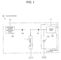
- FIG. 1 is a block diagram showing the schematic configuration of an ignition system 101 having a plasma jet ignition plug (hereinafter, referred to as the "ignition plug") 1.
- the ignition system 101 includes a discharge voltage application means 102 and a plasma power supply 103.
- the discharge voltage application means 102 includes, for example, a CDI-type power supply circuit and is connected to the ignition plug 1 via a reverse current blocking diode 104.
- the discharge voltage application means 101 applies a high voltage to the ignition plug 1 for causing dielectric breakdown across the gap between a center electrode 5 and a ground electrode 27, which will be described later, of the ignition plug 1, thereby generating spark discharge; i.e., the discharge voltage application means 101 is adapted to generate trigger discharge.
- An unillustrated ECU electronic control unit controls timing etc. of trigger discharge.
- the plasma power supply 103 includes a capacitor 105 for storing electric energy to be supplied to the ignition plug 1, and a power unit 106 for charging the capacitor 105.
- the capacitor 105 is grounded at one end and connected at the other end to the ignition plug 1 via a reverse current blocking diode 107 and is configured to allow charge and discharge.
- the electrostatic capacity of the capacitor 105 is determined such that the amount of energy to be supplied for a single generation of plasma (the sum of the amount of energy supplied for the trigger discharge and the amount of energy supplied from the capacitor 105) is 10 mJ to 120 mJ inclusive.
- FIG. 2 is a partially cutaway front view showing the ignition plug 1.
- the direction of an axis CL1 of the ignition plug 1 is referred to as the vertical direction.
- the lower side of the spark plug 1 in FIG. 2 is referred to as the front side of the spark plug 1, and the upper side as the rear side.
- the ignition plug 1 includes a tubular insulator 2 and a tubular metallic shell 3, which holds the insulator 2 therein.
- the insulator 2 is formed from alumina or the like by firing, as well known in the art.
- the insulator 2 as viewed externally, includes a rear trunk portion 10 formed on the rear side; a large-diameter portion 11, which is located frontward of the rear trunk portion 10 and projects radially outward; an intermediate trunk portion 12, which is located frontward of the large-diameter portion 11 and is smaller in diameter than the large-diameter portion 11; and a leg portion 13, which is located frontward of the intermediate trunk portion 12 and is smaller in diameter than the intermediate trunk portion 12.
- the large-diameter portion 11, the intermediate trunk portion 12, and the leg portion 13 of the insulator are accommodated within the metallic shell 3.
- a tapered, stepped portion 14 is formed at a connection portion between the intermediate trunk portion 12 and the leg portion 13. The insulator 2 is seated on the metallic shell 3 at the stepped portion 14.
- the insulator 2 has an axial hole 4 extending therethrough along the axis CL1.
- a center electrode 5 is fixedly inserted into a front end portion of the axial hole 4.
- the center electrode 5 includes an inner layer 5A made of, for example, copper or a copper alloy, which has excellent thermal conductivity, and an outer layer 5B made of a nickel (Ni) alloy (e.g. INCONEL 600 or 610 (trade name)) which contains nickel as a main component. Further, the center electrode 5 assumes a rodlike (circular columnar) shape as a whole.
- the front end surface of the center electrode 5 is indented rearward of the front end surface of the insulator 2 (the constitution of a front end portion of the center electrode 5 will be described later in detail).
- a terminal electrode 6 is fixedly inserted into a rear end portion of the axial hole 4 and projects from the rear end of the insulator 2.
- a circular columnar glass seal layer 9 is disposed within the axial hole 4 between the center electrode 5 and the terminal electrode 6.
- the center electrode 5 and the terminal electrode 6 are electrically connected together via the glass seal layer 9.
- the metallic shell 3 is formed into a tubular shape from a low-carbon steel or a like metal.
- the metallic shell 3 has, on its outer circumferential surface, a threaded portion (externally threaded portion) 15 adapted to mount the ignition plug 1 into a mounting hole of a combustion apparatus (e.g., an internal combustion engine or a fuel cell reformer).
- a combustion apparatus e.g., an internal combustion engine or a fuel cell reformer.
- the metallic shell 3 has, on its outer circumferential surface, a seat portion 16 located rearward of the threaded portion 15.
- a ring-like gasket 18 is fitted to a screw neck 17 at the rear end of the threaded portion 15.
- the metallic shell 3 has, near the rear end thereof, a tool engagement portion 19 having a hexagonal cross section and allowing a tool, such as a wrench, to be engaged therewith when the ignition plug 1 is to be mounted to the combustion apparatus. Also, the metallic shell 3 has a crimp portion 20 provided at a rear end portion thereof for retaining the insulator 2. Further, the metallic shell 3 has an annular engagement portion 21 formed externally at a front end portion thereof and projecting frontward with respect to the direction of the axis CL1. The ground electrode 27, which will be described later, is joined to the engagement portion 21.
- the metallic shell 3 has, on its inner circumferential surface, a tapered, stepped portion 22 adapted to allow the insulator 2 to be seated thereon.
- the insulator 2 is inserted frontward into the metallic shell 3 from the rear end of the metallic shell 3.
- a rear-end opening portion of the metallic shell 3 is crimped radially inward; i.e., the crimp portion 20 is formed, whereby the insulator 2 is fixed in place.
- An annular sheet packing 23 intervenes between the stepped portions 14 and 22 of the insulator 2 and the metallic shell 3, respectively. This retains gastightness of a combustion chamber and prevents outward leakage of fuel gas through a clearance between the leg portion 13 of the insulator 2 and the inner circumferential surface of the metallic shell 3.
- annular ring members 24 and 25 intervene between the metallic shell 3 and the insulator 2 in a region near the rear end of the metallic shell 3, and a space between the ring members 24 and 25 is filled with a powder of talc 26. That is, the metallic shell 3 holds the insulator 2 via the sheet packing 23, the ring members 24 and 25, and the talc 26.
- the ground electrode 27 assumes the form of a disk and is formed from an Ni alloy which contains Ni as a main component.
- the ground electrode 27 is joined to a front end portion of the metallic shell 3 as follows: while the ground electrode 27 is engaged with the engagement portion 21 of the metallic shell 3, an outer circumferential portion of the ground electrode 27 is welded to the engagement portion 21.
- the ground electrode 27 is in surface contact with the front end surface of the insulator 2 and has a cylindrical through hole 28 which extends through a central portion thereof in the thickness direction.
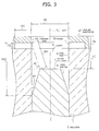
- the wall surface of the axial hole 4 and the front end surface of the center electrode 5 define a cavity 31.
- the cavity 31 communicates with an ambient atmosphere via the through hole 28.
- the cavity 31 is a cylindrical space defined by the wall surface of the axial hole 4 and a plane which contains the front end of the center electrode 5 and is orthogonal to the axis CL1.
- the ground electrode 27 is joined such that the through hole 28 and the axial hole 4 are coaxial (i.e., the center of the through hole 28 is positioned on the axis CL1). Additionally, the diameter of the cavity 31 is substantially constant with respect to the direction of the axis CL1.
- the shape of the cavity 31 is not necessarily an exactly cylindrical shape.
- the cavity 31 may be shaped in such a manner as to be tapered frontward with respect to the direction of the axis CL1, and the wall surface of the axial hole 4 which partially defines the cavity 31 may be inclined up to ⁇ 5° with respect to the axis CL1.
- a diameter DC of the cavity 31, which will be described later is the average of diameters measured at a plurality of positions located along the direction of the axis CL1 (for example, diameters measured at the front end and the rear end of the cavity 31).
- a front end portion of the center electrode 5 is formed into a taper portion 51 which tapers frontward with respect to the direction of the axis CL1.
- the front end of the taper portion 51 has a relatively small diameter such that the outside diameter of the front end is smaller than the diameter of the through hole 28.
- the position of the front end portion of the center electrode 5 within the axial hole 4 is adjusted such that the length of the cavity 31 along a radial direction (the length measured orthogonally to the axis CL1) is longer than the length of the cavity 31 along the direction of the axis CL1. That is, when DC (mm) represents the diameter of the cavity 31, and LC (mm) represents the length of the cavity 31 along the direction of the axis CL1 (the distance along the axis CL1 between the opening of the axial hole 4 and the front end of the center electrode 5), the dimensional relation 0.5 ⁇ LC/DC ⁇ 1.0 is satisfied. In the present embodiment, the diameter DC is relatively small (e.g., 1.2 mm or less).
- a shortest distance SD1 (mm) between the wall surface of the through hole 28 and the front end portion (the taper portion 51) of the center electrode 5 is specified to be 0.3 mm to 1.3 mm inclusive (in the present embodiment, 0.7 mm ⁇ SD1 ⁇ 1.0 mm).
- the position of the rear end of the taper portion 51 along the direction of the axis CL1 is determined according to the shortest distance SD1.
- the shortest distance SD2 is determined so as to satisfy the dimensional relation 1.2 x SD1 ⁇ SD2.
- the shortest distance SD2 is determined such that the length along the direction of the axis CL1 between the front end of the axial hole 4 and the rear end of the taper portion 51 is greater than the diameter of the cavity 31.
- the shortest distance SD2 is determined as follows. That is, preferably, when the shortest distance SD1 is 0.3 mm to 0.7 mm inclusive, the shortest distance SD2 is determined so as to satisfy the dimensional relation 1.1 x SD1 ⁇ SD2; when the shortest distance SD1 is in excess of 1.0 mm to 1.2 mm inclusive, the shortest distance SD2 is determined so as to satisfy the dimensional relation 1.3 x SD1 ⁇ SD2; and when the shortest distance SD1 is in excess of 1.2 mm to 1.3 mm inclusive, the shortest distance SD2 is determined so as to satisfy the dimensional relation 1.4 x SD1 ⁇ SD2.
- a recess 32 which is shaped annularly about the axis CL1 and opens toward the axis CL1 (the cavity 31) is formed between the front end surface of the insulator 2 and a surface of the ground electrode 27 located on a side toward the insulator 2.
- the recess 32 has a length LG (mm) of opening of 0.05 mm to 0.5 mm inclusive as measured along the axis CL1.
- the width of the recess 32 i.e., a shortest distance DG (mm) between the opening of the recess 32 and an innermost portion of the recess 32 as measured along the front end surface of the insulator 2, is determined so as to be sufficiently long as compared with the length LG of the recess 32.
- the width of the recess 32 is determined so as to satisfy the dimensional relation DG ⁇ 1.1 x LG.
- the relative position between the wall surface of the through hole 28 and the front end portion of the center electrode 5 is adjusted so as to bring the direction of discharge closer to the direction of the axis CL1.
- the relative position between the through hole 28 and the center electrode 5 is adjusted so as to establish the following: as viewed on a section which contains the axis CL1, an angle 91 formed between a straight line orthogonal to the axis CL1 and the shortest line segment which connects the wall surface of the through hole 28 and the front end portion of the center electrode 5, and formed on a side toward the wall surface of the axial hole 4, is 15° or greater.
- an angle ⁇ 2 formed between the taper portion 51 and the wall surface of the cavity 31 (the axial hole 4) and formed on a front side with respect to the direction of the axis CL1 is specified to be 10° or greater.
- a thickness TS of the ground electrode 27 (excluding a portion where the recess 32 is formed) is rendered greater than the length LG of the recess 32 and specified to be 0.3 mm to 1.0 mm inclusive.
- the diameter DC of the cavity 31 and the axial length LC of the cavity 31 satisfy the dimensional relation 0.5 ⁇ LC/DC ⁇ 1.0.
- the distance between the center electrode 5 and the ground electrode 27 can be reduced, whereby a discharge voltage required for generation of spark discharge can be reduced.
- erosion of the center electrode 5 can be mitigated, whereby spark discharge and, in turn, plasma, can be generated over a longer period of time.
- a front end portion of the center electrode 5 is formed into the taper portion 51, and the outside diameter of the front end of the taper portion 51 is smaller than the diameter of the through hole 28. Therefore, at an early stage, aerial discharge can be actively generated between the front end of the taper portion 51 and the wall surface of the through hole 28, and plasma can be generated without imposing restraint on propagation. As a result, a larger plasma jet can be generated, so that at the early stage, sufficient ignition performance can be achieved.
- the radial expansion of the cavity 31 is restrained.
- the shape of the cavity 31 can be such that the axial length is relatively long.
- the blown-off velocity of plasma can be increased with erosion of the center electrode 5. Therefore, even at a stage where erosion of the center electrode 5 has progressed, excellent ignition performance can be achieved.
- erosion of the center electrode 5 at an early stage is restrained, whereby plasma can be generated over a longer period of time. Also, not only at the early stage, but also even at a stage where erosion of the center electrode 5 has progressed, excellent ignition performance can be achieved. That is, according to the present embodiment, excellent ignition performance can be maintained over a very long period of time.
- the shortest distance SD2 is sufficiently long in relation to the shortest distance SD1.
- the recess 32 having a length LG of 0.05 mm or greater and a width DG which is 1.1 times or greater the length LG is provided between the ground electrode 27 and the front end surface of the insulator 2. Therefore, at an early stage, the generation of creeping discharge can be prevented more reliably.
- the angle ⁇ 1 is specified to be 15° or greater; i.e., a direction along which aerial discharge is generated (a direction along which plasma is blown off) is determined so as to approach the direction of the axis CL1. Therefore, plasma can be blown off vigorously from the through hole 28, so that the blown-off length of flame can be further increased. As a result, quite excellent ignition performance can be achieved.
- the angle ⁇ 2 is specified to be 10° or greater, when liquid, such as fuel, enters the cavity 31, a situation in which the liquid is held between the taper portion 51 and the wall surface of the axial hole 4 can be sufficiently restrained. By virtue of this, the generation of creeping discharge via the liquid can be restrained; eventually, at an early stage, aerial discharge can be generated more reliably.
- the ground electrode 27 has a thickness of 0.3 mm to 1.0 mm inclusive, durability of the ground electrode 27 can be sufficiently ensured.
- the ignition plug 1 can generate a large plasma jet through generation of aerial discharge.
- electric energy to be supplied from the plasma power supply 103 to the ignition plug 1 can be relatively low.
- erosion of the center electrode 5 etc. can be effectively restrained.
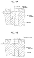
- a front end portion of a center electrode 5S2 has a circular columnar shape.
- Samples of the conventional plasma jet ignition plugs having different LC/DC ratios were fabricated; specifically, there were fabricated the conventional plug samples which have a length LC of the cavity of 0.5 mm as measured along the direction of the axis CL1 and differ in the diameter DC of the cavity, the conventional plug samples which have a length LC of 0.7 mm and differ in the diameter DC, and the conventional plug samples which have a length LC of 1.0 mm and differ in the diameter DC.
- the fabricated conventional plug samples were mounted to a 4-cylinder engine of 1.5 L displacement. The engine was operated at a speed of 1,600 rpm and a boost pressure of 320 mmHg.
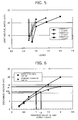
- FIG. 5 is a graph showing the relation between LC/DC and the limit air-fuel ratio.
- the test results of the samples having a length LC of 0.5 mm are plotted with circles; the test results of the samples having a length LC of 0.7 mm are plotted with triangles; and the test results of the samples having a length LC of 1.0 mm are plotted with squares.
- the test results of the conventional plug samples are plotted with solid black circles, triangles, and squares.
- the conventional plug samples having an LC/DC of less than 1.0 show a significant drop in limit air-fuel ratio, indicating deterioration in ignition performance at an early stage. Conceivably, this is for the following reason: as a result of LC/DC being less than 1.0, plasma is apt to radially expand, causing a reduction in the blown-off velocity of flame along the axial direction.
- invention samples There were fabricated the invention samples which have a length LC of 0.5 mm, 0.7 mm, and 1.0 mm; whose cavities are shaped so as to have the LC/DC ratios which have caused a significant drop in limit air-fuel ratio in the conventional plug samples; and whose center electrodes have tapered front end portions; i.e., taper portions.
- FIG. 5 the test results of the invention samples are shown with an outlined circle, an outlined triangle, and an outlined square.
- the invention samples have the LC/DC ratios which have caused a significant drop in limit air-fuel ratio in the conventional plug samples, the invention samples have excellent ignition performance.
- this is for the following reason: by virtue of the center electrode having a tapered front end portion; i.e., a taper portion, aerial discharge is easily generated between the taper portion and the ground electrode; as a result, a larger plasma jet is generated.
- the ignition plug according to the embodiment of the present invention has ignition performance superior to that of the conventional ignition plug, but may fail to achieve desired ignition performance. Therefore, in order to reliably achieve excellent ignition performance at the early stage, the dimensional relation 0.5 ⁇ LC/DC is preferred.
- aerial discharge samples which have a center electrode 5S1 whose front end portion is formed into a circular columnar protrusion PT as shown in FIG. 4(a) , and which differ in gap length GD1, as well as a plurality of samples (creeping discharge samples) which have a center electrode 5S2 having a circular columnar front end portion as shown in FIG. 4(b) and which differ in gap length GD2.
- aerial discharge samples when voltage is applied, electric field intensity is relatively high, and aerial discharge is likely to be generated between the ground electrode 27 and the protrusion PT, which is located closest to the ground electrode.
- FIG. 6 is a graph showing the relation between the gap length and the discharge voltage in the samples.
- the discharge voltages of the aerial discharge samples are plotted with circles, and the discharge voltages of the creeping discharge samples are plotted with triangles.
- the recess is not formed between the ground electrode and the insulator.
- the maximum value of the gap length GD1 at which aerial discharge was generated in an aerial discharge sample and the maximum value of the gap length GD2 at which creeping discharge was generated in a creeping discharge sample were obtained for each of applied discharge voltages.
- the discharge voltage is 10.8 kV
- the maximum value of the gap length GD1 at which aerial discharge is generated in an aerial discharge sample is 1.0 mm
- the maximum value of the gap length GD2 at which creeping discharge is generated in a creeping discharge sample is 1.2 mm.
- the maximum value of the gap length GD2 is divided by the maximum value of the gap length GD1.
- the obtained quotient is rounded up to one decimal place, thereby yielding a value ⁇ .
- the value ⁇ obtained for a certain discharge voltage is multiplied by the maximum value of the gap length GD1 at the discharge voltage, the obtained value is equal to or greater than the maximum value of the gap length GD2 at the discharge voltage.
- FIG. 7 shows the value ⁇ calculated for the maximum value of the gap length GD1.
- the obtained values are greater than the corresponding maximum values of the gap length GD2 at which creeping discharge is generated.
- the shortest distance SD1 and the shortest distance SD2 satisfy the dimensional relation 1.1 x SD1 ⁇ SD2; with 0.7 ⁇ SD1 ⁇ 1.0, SD1 and SD2 satisfy the dimensional relation 1.2 x SD1 ⁇ SD2; with 1.0 ⁇ SD1 ⁇ 1.2, SD1 and SD2 satisfy the dimensional relation 1.3 x SD1 ⁇ SD2; and with 1.2 ⁇ SD1 ⁇ 1.3, SD1 and SD2 satisfy the dimensional relation 1.4 x SD1 ⁇ SD2. It may be said that, through satisfaction of the above dimensional relations, ignition performance at an early stage can be further improved.
- the gap length GD2 in the case of a gap length GD1 in excess of 1.3 mm, for easier generation of aerial discharge than generation of creeping discharge, the gap length GD2 must be increased excessively (for example, in the case of a discharge voltage of 14 kV, the gap length GD2 must be 2.5 mm or greater).
- the taper portion becomes excessively long along the axial direction; as a result, there may arise a deterioration in heat transfer of the center electrode, a deterioration in strength of the center electrode against vibration, and a like problem. Therefore, preferably, the shortest distance SD1 is 1.3 mm or less.
- ignition plug samples which have an SD2/SD1 of 1.1 or 1.4 and are provided with the recess and which differ in the length LG of opening of the recess.
- the samples were mounted to a predetermined chamber. While the chamber pressure was held at 0.4 MPa, discharge voltage was applied a plurality of times, and the incidence of aerial discharge (aerial discharge rate) was measured.
- ignition plug samples which have an SD2/SD1 of 1.1 to 1.4 and are not provided with the recess were measured for a flame area SO by laterally observing blown-off flames.
- ignition plug samples which have an SD2/SD1 of 1.1 to 1.4 and are provided with the recess and which differ in the length LG of opening of the recess were measured for a flame area SF.
- the percentage of the flame area SF to the flame area SO (SF/S0 hereinafter, referred to as the flame area percentage) was obtained.
- FIG. 8 is a graph showing the relation of the length LG to the aerial discharge rate and the flame area percentage.
- the aerial discharge rates of the samples having an SD2/SD1 of 1.1 are plotted with circles, and the aerial discharge rates of the samples having an SD2/SD1 of 1.4 are plotted with triangles.
- the flame area percentages are plotted with squares.
- the samples have a sufficiently large width DG of the recess of 1.0 mm.
- the samples having a length LG of opening of the recess of 0.05 mm or greater exhibit a great increase in aerial discharge rate. Conceivably, this is for the following reason. Since a sufficiently large length LG of 0.05 mm or greater is employed, a relatively large space (gap) is formed on a route which extends along the wall surface of the axial hole between the ground electrode and the wall surface of the through hole. Thus, a discharge voltage required for generation of aerial discharge is usually higher than that required for generation of creeping discharge, but the discharge voltage required for generation of creeping discharge along the route increases to an extent corresponding to the space. As a result, creeping discharge is less likely to be generated, whereas aerial discharge is more likely to be generated.
- test data concerning the flame area percentage indicate that through provision of the recess, the size of a blown-off flame can be increased. Conceivably, this is for the following reason. By virtue of provision of the recess, transfer of heat of flame to the ground electrode can be reliably restrained.
- the samples having a length LG of opening of the recess in excess of 0.5 mm show a reduction in the size of a blown-off flame. Conceivably, this is for the following reason. As a result of excessive expansion of opening of the recess, flame enters the recess and is thus less likely to be blown off from the through hole.
- the recess is provided between the insulator and the ground electrode, and the length LG of opening of the recess is 0.05 mm to 0.5 mm inclusive.
- the length LG is 0.15 mm or greater.
- the length LG of opening of the recess corresponds to the gap length GD1
- the following can be said: in the case of a length LG of 0.5 mm or less, by means of the width of the recess (the shortest distance DG between the front end of the axial hole and the innermost portion of the recess as measured along the surface of the insulator) being 1.1 times or greater the length LG, the generation of creeping discharge between the center electrode and the innermost portion of the recess can be restrained.
- the shortest distance DG (mm) is determined so as to satisfy the dimensional relation DG ⁇ 1.1 ⁇ LG.
- FIG. 9 shows the results of the test.
- the samples having an angle ⁇ 1 of 15° or greater exhibit a marked improvement in ignition performance.
- this is for the following reason: by means of the angle ⁇ 1 being 15° or greater, the direction of spark discharge can be brought closer to the direction of the axis CL1, and, in turn, flame can be smoothly blown off outward.
- the angle ⁇ 1 is 15° or greater.
- the prepared test machine includes a pendulum and a support, which supports the pendulum and extends in the vertical direction.
- the cavities of the samples were filled with colored water.
- Each of the samples was attached to a distal end portion of the pendulum.
- the pendulum was moved away from the support by 15° and was then released for free fall so as to hit the sample against the support, thereby shaking off water from the cavity.
- the sample was checked whether or not a bridge of water was present between the taper portion and the wall surface of the axial hole.
- the angle ⁇ 2 is 10° or greater.
- the present invention is not limited to the above-described embodiment, but may be embodied, for example, as follows. Of course, applications and modifications other than those exemplified below are also possible.
- the diodes 104 and 107 are provided for preventing current flow from one of the discharge voltage application means 102 and the plasma power supply 103 to the other.
- the diodes 104 and 107 are provided for preventing current flow from one of the discharge voltage application means 102 and the plasma power supply 103 to the other.
- a configuration without provision of such diodes avoids the following problem: the existence of diodes restrains resonance of power supplied from the plasma power supply, causing deterioration in power applied to the plasma jet ignition plug 1. Therefore, power applied to the plasma jet ignition plug 1 can be increased, whereby ignition performance can be further improved.
- 1 plasma jet ignition plug
- 2 insulator
- 4 axial hole
- 5 center electrode
- 27 ground electrode
- 28 through hole
- 31 cavity
- 32 recess
- 51 taper portion
- 101 ignition system
- 102 discharge voltage application means
- 103 plasma power supply
- CL1 axis
Landscapes
- Spark Plugs (AREA)
- Ignition Installations For Internal Combustion Engines (AREA)
Abstract
Description
- The present invention relates to a plasma jet ignition plug for igniting an air-fuel mixture through formation of plasma and to an ignition system having the plasma jet ignition plug.
- Conventionally, a combustion apparatus, such as an internal combustion engine, uses a spark plug for igniting an air-fuel mixture through spark discharge. In recent years, in order to meet demand for high output and low fuel consumption, a plasma jet ignition plug has been proposed, since the plasma jet ignition plug provides quick propagation of combustion and can more reliably ignite even a lean air-fuel mixture having a higher ignition-limit air-fuel ratio.
- Generally, the plasma jet ignition plug includes a tubular insulator having an axial hole, a center electrode inserted into the axial hole in such a manner that a front end surface thereof is located internally of a front end surface of the insulator, a metallic shell disposed externally of the outer circumference of the insulator, and an annular ground electrode joined to a front end portion of the metallic shell. Also, the plasma jet ignition plug has a space (cavity) defined by the front end surface of the center electrode and a wall surface of the axial hole. The cavity communicates with an ambient atmosphere via a through hole formed in the ground electrode.
- Additionally, such the plasma jet ignition plug ignites an air-fuel mixture as follows. First, voltage is applied between the center electrode and the ground electrode, thereby generating spark discharge therebetween and thus causing dielectric breakdown therebetween. In this condition, high-energy current is applied between the center electrode and the ground electrode for effecting transition of a discharge state, thereby generating plasma within the cavity. The generated plasma is blown off through an opening of the cavity, thereby igniting the air-fuel mixture.
- Meanwhile, according to a conceivable method for achieving enhanced ignition performance, current having higher energy is applied after generation of spark discharge for generating a larger plasma jet. However, when such high-energy current is applied, the center electrode becomes likely to erode, potentially resulting in an abrupt increase in voltage required for generation of spark discharge.
- According to a known method for coping with the above problem (refer to, for example, Patent Document 1), the wall of the cavity has a stepped shape for imparting a throttle to the cavity, whereby even when current having relatively low energy is applied, excellent ignition performance can be achieved. Also, according to a proposed technique (refer to, for example, Patent Document 2), the axial length of the cavity is relatively long for increasing the blown-off velocity of plasma, whereby the blown-off length of flame is increased, thereby improving ignition performance.
-
- [Patent Document 1] Japanese Patent Application Laid-Open (kokai) No.
2007-287666 - [Patent Document 2] Japanese Patent Application Laid-Open (kokai) No.
2006-294257 - However, in association with the phenomenon (so-called channeling) that spark discharge erodes a portion of the insulator located on a spark discharge path, the technique described in
Patent Document 1 involves the following problem: since the wall of the cavity is curved (bent), the insulator is apt to be eroded at the curved (bent) portion. Further, since a spark discharge path which passes through an eroded portion of the insulator becomes shorter than other spark discharge paths, spark discharge is generated in a concentrated manner along the spark discharge path, causing local concentration of channeling. As a result, the insulator is eroded in a deep streaky manner; thus, a groove lying on a line which connects the center electrode and a portion of the ground electrode located toward the outer circumference may be formed on the wall of the cavity. Spark discharge is generated along this groove. Even though plasma is generated, the plasma is less likely to be blown off outward due to the existence of the ground electrode. That is, according to the technique described inPatent Document 1, excellent ignition performance can be achieved at an early stage, but ignition performance may drastically deteriorate in the course of use. - Meanwhile, when, as in the case of the technique described in
Patent Document 2, the axial length of the cavity is relatively long, the distance between the center electrode and the ground electrode becomes relatively long. Thus, a discharge voltage required for generation of spark discharge increases, causing rapid erosion of the center electrode and the insulator. As a result, ignition performance deteriorates rapidly, and difficulty may be encountered in generating spark discharges over a long period of time. - The present invention has been conceived in view of the above circumstances, and an object of the invention is to provide a plasma jet ignition plug capable of maintaining excellent ignition performance over a long period of time and an ignition system using the same.
- Configurations suitable for achieving the above object will next be described in itemized form. If needed, actions and effects peculiar to the configurations will be described additionally.
- Configuration 1: A plasma jet ignition plug of the present configuration comprises a tubular insulator having an axial hole extending therethrough in a direction of an axis; a rodlike center electrode inserted into the axial hole in such a manner that a front end thereof is located rearward of a front end of the insulator with respect to the direction of the axis; and a ground electrode disposed frontward of the front end of the insulator. The insulator has a cavity which is defined by a wall surface of the axial hole and a front end surface of the center electrode and opens frontward. The ground electrode has a through hole for establishing communication between the cavity and an ambient atmosphere. The plasma jet ignition plug is characterized in that: a front end portion of the center electrode is formed into a taper portion whose diameter reduces frontward with respect to the direction of the axis; an outside diameter of a front end of the taper portion is smaller than a diameter of the through hole; and a diameter of the cavity is substantially constant with respect to the direction of the axis, and the diameter DC (mm) of the cavity and a length LC (mm) of the cavity along the direction of the axis satisfy a dimensional relation

- The wall surface of the axial hole which partially defines the cavity may be inclined up to ±5° with respect to the axis. The shape of the cavity is not necessarily an exactly cylindrical shape (for example, the shape may be a frontward tapered shape). In the case where the wall surface of the axial hole which partially defines the cavity is inclined with respect to the axis, the "diameter of the cavity" means the average diameter of the cavity with respect to the direction of the axis.
- According to the
above configuration 1, the diameter DC of the cavity and the length LC of the cavity along the direction of the axis satisfy the dimensional relation 0.5 ≤ LC/DC < 1.0. That is, the cavity is shaped such that its length along a direction orthogonal to the axis is relatively long. Thus, as compared with the case where the axial length of the cavity is relatively long, the distance between the center electrode and the ground electrode can be reduced, whereby a discharge voltage required for generation of spark discharge can be reduced. As a result, erosion of the center electrode can be mitigated, whereby spark discharge and, in turn, plasma, can be generated over a longer period of time. - Meanwhile, when the length of the cavity along a direction orthogonal to the axis is increased, the blown-off velocity of plasma may be reduced. However, according to the
above configuration 1, a front end portion of the center electrode is formed into a taper portion, and the outside diameter of the front end of the taper portion is smaller than the diameter of the through hole of the ground electrode. Therefore, at an early stage, spark discharge in the air (aerial discharge) can be actively generated between the front end of the taper portion and the wall surface of the through hole, and plasma can be generated without imposing restraint on propagation. As a result, a larger plasma jet can be generated, so that at the early stage, sufficient ignition performance can be achieved. - Also, since, at the early stage, aerial discharge is actively generated, the generation of spark discharge along the surface of the insulator (creeping discharge) is restrained to the greatest possible extent. Thus, coupled with the fact that the diameter of the cavity is substantially constant, erosion of the insulator and the generation of channeling can be more reliably prevented.
- Additionally, as mentioned above, since erosion of the insulator is restrained, the radial expansion of the cavity is restrained. Thus, at a stage where the center electrode (taper portion) is eroded, the shape of the cavity can be such that the axial length is relatively long. Thus, the blown-off velocity of plasma can be increased with erosion of the center electrode. Therefore, even at a stage where erosion of the center electrode has progressed, excellent ignition performance can be achieved.
- As mentioned above, according to the
above configuration 1, erosion of the center electrode at an early stage is restrained, whereby plasma can be generated over a longer period of time. Also, not only at the early stage, but also even at a stage where erosion of the center electrode has progressed, excellent ignition performance can be achieved. That is, according to theabove configuration 1, excellent ignition performance can be maintained over a very long period of time. - Configuration 2: A plasma jet ignition plug of the present configuration is characterized in that, in the
above configuration 1, when SD1 (mm) represents the shortest distance between the wall surface of the through hole and the front end portion of the center electrode, and SD2 (mm) represents the shortest distance between the wall surface of the through hole and the center electrode as measured along the wall surface of the axial hole,
with 0.3 ≤ SD1 ≤ 0.7, the dimensional relation 1.1 x SD1 < SD2 is satisfied,
with 0.7 < SD1 ≤ 1.0, the dimensional relation 1.2 x SD1 < SD2 is satisfied,
with 1.0 < SD1 ≤ 1.2, the dimensional relation 1.3 x SD1 < SD2 is satisfied, and
with 1.2 < SD1 ≤ 1.3, the dimensional relation 1.4 x SD1 < SD2 is satisfied. - According to the
above configuration 2, the shortest distance SD2 (i.e., the length of a discharge path when creeping discharge is generated) is sufficiently long in relation to the shortest distance SD1 (i.e., the length of a discharge path when aerial discharge is generated). Thus, at an early stage, aerial discharge can be generated more reliably; as a result, the actions and effects yielded by theabove configuration 1 can be more reliably yielded. - When the shortest distance SD1 is less than 0.3 mm, the size of a plasma jet to be generated becomes relatively small, so that ignition performance at the early stage may deteriorate to some extent. When the shortest distance SD1 is in excess of 1.3 mm, in order to more reliably generate aerial discharge, the shortest distance SD2 must be increased excessively (i.e., the axial length of the taper portion must be increased excessively). Thus, there may arise a deterioration in strength of the center electrode against vibration and a deterioration in heat transfer of the center electrode in association with reduction in the contact area between the center electrode and the insulator (axial hole). In view of these points, preferably, the shortest distance SD1 is 0.3 mm to 1.3 mm inclusive.
- Configuration 3: A plasma jet ignition plug of the present configuration is characterized by, in the
above configuration
0.05 ≤ LG ≤ 0.5 and DG ≥ 1.1 x LG are satisfied, where LG (mm) is the length of opening of the recess as measured along the axis, and DG (mm) is the shortest distance between the opening of the recess and an innermost portion of the recess as measured along the front end surface of the insulator. - According to the
above configuration 3, the recess having a sufficiently large opening; specifically, an opening having a length of 0.05 mm or greater, is provided between the ground electrode and the front end surface of the insulator. That is, a relatively large gap is formed on a discharge path associated with creeping discharge which is generated along the wall surface of the axial hole between the center electrode and the wall surface of the through hole. Therefore, at an early stage, the generation of creeping discharge on the discharge path can be prevented more reliably. - Also, the shortest distance DG between the opening of the recess and the innermost portion of the recess (width of the recess) as measured along the front end surface of the insulator is set sufficiently long as compared with the length LG of the opening. Therefore, the generation of creeping discharge between the center electrode and the innermost portion of the recess can be prevented more reliably.
- As mentioned above, according to the
above configuration 3, at the early stage, the generation of creeping discharge can be effectively restrained, so that aerial discharge can be generated more reliably. Therefore, ignition performance at the early stage can be further improved. - Configuration 4: A plasma jet ignition plug of the present configuration is characterized in that, in any one of the
above configurations 1 to 3, as viewed on a section which contains the axis, an angle of 15° or greater is formed between a straight line orthogonal to the axis and the shortest line segment which connects the wall surface of the through hole and the front end portion of the center electrode. - According to the
above configuration 4, the angle between the shortest line segment and the straight line orthogonal to the axis is 15° or greater. That is, a direction along which aerial discharge is generated (a direction along which plasma is blown off) is determined so as not to approach a direction orthogonal to the axis. Therefore, plasma can be blown off vigorously from the through hole, so that the blown-off length of flame can be further increased. As a result, quite excellent ignition performance can be achieved. - Configuration 5: A plasma jet ignition plug of the present configuration is characterized in that, in any one of the
above configurations 1 to 4, as viewed on a section which contains the axis, the taper portion of the center electrode and the wall surface of the cavity form an angle of 10° or greater. - According to the
above configuration 5, when liquid, such as fuel, enters the cavity, a situation in which the liquid is held between the taper portion and the wall surface of the axial hole can be sufficiently restrained. Therefore, the generation of creeping discharge via the liquid can be restrained; eventually, at an early stage, aerial discharge can be generated more reliably. - The greater the angle between the taper portion and the wall surface of the cavity, the greater the extent to which the liquid holding power can be weakened. Therefore, the angle is preferably 15° or greater, more preferably 20° or greater.
- Configuration 6: A plasma jet ignition plug of the present configuration is characterized in that, in any one of the
above configurations 1 to 5, the ground electrode has a thickness of 0.3 mm to 1.0 mm inclusive. - According to the
above configuration 6, the ground electrode, which is disposed most frontward in the plasma jet ignition plug, has a thickness of 1.0 mm or less. Therefore, a deterioration in heat transfer in the ground electrode can be prevented more reliably, whereby erosion resistance of the ground electrode can be improved. - Meanwhile, the thickness of the ground electrode is specified to be 0.3 mm or greater. Therefore, allowance for erosion caused by spark discharge can be sufficiently provided, whereby spark discharge and plasma can be generated over a long period of time.
- Configuration 7: A plasma jet ignition plug of the present configuration is characterized in the following: in any one of the
above configurations 1 to 6, at least the front end portion of the center electrode is formed from tungsten (W) or a W alloy, and at least a portion of the ground electrode which forms the through hole is formed from an iridium (Ir) alloy or a platinum (Pt) alloy. - According to the above configuration 7, at least the front end portion of the center electrode is formed from W or a W alloy, and at least the portion of the ground electrode which forms the through hole is formed from an Ir alloy or a Pt alloy. Therefore, durability of the electrodes against spark discharge can be improved, and spark discharge and, in turn, plasma, can be generated over a longer period of time.
- Configuration 8: An ignition system comprises a plasma jet ignition plug according to any one of the
above configurations 1 to 7 and a plasma power supply for supplying power to the plasma jet ignition plug for generating plasma within the cavity. The ignition system is characterized in that the plasma power supply has an output of 10 mJ to 120 mJ inclusive. - The plasma jet ignition plug of any one of the
above configurations 1 to 7 can generate a large plasma jet through generation of aerial discharge. Thus, even when electric energy to be supplied from the plasma power supply to the plasma jet ignition plug is relatively low, the blown-off length of flame can be sufficiently long. Therefore, even though, as in the above configuration 8, the plasma power supply has a relatively low output of 10 mJ to 120 mJ inclusive, sufficient ignition performance can be achieved. Also, by virtue of employment of a relatively low output, erosion of the center electrode, etc. can be effectively restrained, so that spark discharge and, in turn, plasma, can be generated over a long period of time. - In order to generate plasma more reliably, preferably, the plasma power supply has an output of 10 mJ or greater.
- Meanwhile, in view of reliable restraint of erosion of the center electrode, etc., reducing the output of the plasma power supply is preferred. Therefore, the output is preferably 10 mJ to 80 mJ inclusive, more preferably 10 mJ to 40 mJ inclusive.
- Configuration 9: An ignition system of the present configuration is characterized in the following: in the above configuration 8, discharge voltage application means for applying voltage across a gap formed between the center electrode and the ground electrode is provided, and the plasma power supply is connected to an intermediate position between the plasma jet ignition plug and the discharge voltage application means, in parallel with the plasma jet ignition plug.
- According to the
above configuration 9, the plasma power supply is provided on a side toward the discharge voltage application means, in parallel with the plasma jet ignition plug. By means of an output voltage from the discharge voltage application means, output for generation of plasma (i.e., output of the plasma power supply) can be obtained. Therefore, the plasma power supply does not need to have a separate power unit or the like, whereby system size and manufacturing cost can be reduced. - In some cases, diodes are provided for preventing current flow from one of the discharge voltage application means and the plasma power supply to the other. However, the
above configuration 9 does not require the provision of such diodes. Therefore, manufacturing cost can be further reduced. - Also, a configuration without provision of such diodes avoids the following problem: the existence of diodes restrains resonance of power supplied from the plasma power supply, causing deterioration in energy applied to the plasma jet ignition plug. Therefore, energy applied to the plasma jet ignition plug can be increased, whereby ignition performance can be further improved.
- A capacitor, for example, can be used as the plasma power supply.
-
- [
FIG. 1 ] Block diagram showing the schematic configuration of an ignition system. - [
FIG. 2 ] Partially cutaway front view showing the configuration of a plasma jet ignition plug. - [
FIG. 3 ] Enlarged sectional view showing the configuration of a front end portion of a center electrode, and its periphery. - [
FIG. 4 ] A pair of fragmentary, enlarged, sectional views, wherein (a) shows the configuration of a center electrode and its periphery of a test sample of an ignition plug, and (b) shows the configuration of a center electrode and its periphery of a test sample of a conventional ignition plug. - [
FIG. 5 ] Graph showing the relation between LC/DC and the limit air-fuel ratio in conventional plug samples and invention samples. - [
FIG. 6 ] Graph showing the relation between a discharge voltage and the maximum gap length across which spark discharge is generated at the discharge voltage, in creeping discharge samples and aerial discharge samples. - [
FIG. 7 ] Graph showing a value α for the maximum value of gap length GD1, the product of the value α and the maximum value of the gap length GD1 across which aerial discharge is generated at a predetermined discharge voltage, being equal to or greater than the maximum value of gap length GD2 across which creeping discharge is generated at the predetermined discharge voltage. - [
FIG. 8 ] Graph showing aerial discharge rates and flame area percentages of those samples which differ in length LG. - [
FIG. 9 ] Graph showing the results of an ignition performance evaluation test conducted on samples which differ in angle θ1. - [
FIG. 10 ] Block diagram showing the schematic configuration of an ignition system according to another embodiment of the present invention. - An embodiment of the present invention will next be described with reference to the drawings.
FIG. 1 is a block diagram showing the schematic configuration of anignition system 101 having a plasma jet ignition plug (hereinafter, referred to as the "ignition plug") 1. Theignition system 101 includes a discharge voltage application means 102 and a plasma power supply 103. - The discharge voltage application means 102 includes, for example, a CDI-type power supply circuit and is connected to the
ignition plug 1 via a reversecurrent blocking diode 104. The discharge voltage application means 101 applies a high voltage to theignition plug 1 for causing dielectric breakdown across the gap between acenter electrode 5 and aground electrode 27, which will be described later, of theignition plug 1, thereby generating spark discharge; i.e., the discharge voltage application means 101 is adapted to generate trigger discharge. An unillustrated ECU (electronic control unit) controls timing etc. of trigger discharge. - The plasma power supply 103 includes a
capacitor 105 for storing electric energy to be supplied to theignition plug 1, and apower unit 106 for charging thecapacitor 105. Thecapacitor 105 is grounded at one end and connected at the other end to theignition plug 1 via a reversecurrent blocking diode 107 and is configured to allow charge and discharge. The electrostatic capacity of thecapacitor 105 is determined such that the amount of energy to be supplied for a single generation of plasma (the sum of the amount of energy supplied for the trigger discharge and the amount of energy supplied from the capacitor 105) is 10 mJ to 120 mJ inclusive. - Next, the configuration of the
ignition plug 1 will be described in detail.FIG. 2 is a partially cutaway front view showing theignition plug 1. InFIG. 2 , the direction of an axis CL1 of theignition plug 1 is referred to as the vertical direction. In the following description, the lower side of thespark plug 1 inFIG. 2 is referred to as the front side of thespark plug 1, and the upper side as the rear side. - The
ignition plug 1 includes atubular insulator 2 and a tubularmetallic shell 3, which holds theinsulator 2 therein. - The
insulator 2 is formed from alumina or the like by firing, as well known in the art. Theinsulator 2, as viewed externally, includes arear trunk portion 10 formed on the rear side; a large-diameter portion 11, which is located frontward of therear trunk portion 10 and projects radially outward; anintermediate trunk portion 12, which is located frontward of the large-diameter portion 11 and is smaller in diameter than the large-diameter portion 11; and aleg portion 13, which is located frontward of theintermediate trunk portion 12 and is smaller in diameter than theintermediate trunk portion 12. Additionally, the large-diameter portion 11, theintermediate trunk portion 12, and theleg portion 13 of the insulator are accommodated within themetallic shell 3. A tapered, steppedportion 14 is formed at a connection portion between theintermediate trunk portion 12 and theleg portion 13. Theinsulator 2 is seated on themetallic shell 3 at the steppedportion 14. - Further, the
insulator 2 has anaxial hole 4 extending therethrough along the axis CL1. Acenter electrode 5 is fixedly inserted into a front end portion of theaxial hole 4. Thecenter electrode 5 includes aninner layer 5A made of, for example, copper or a copper alloy, which has excellent thermal conductivity, and anouter layer 5B made of a nickel (Ni) alloy (e.g. INCONEL 600 or 610 (trade name)) which contains nickel as a main component. Further, thecenter electrode 5 assumes a rodlike (circular columnar) shape as a whole. The front end surface of thecenter electrode 5 is indented rearward of the front end surface of the insulator 2 (the constitution of a front end portion of thecenter electrode 5 will be described later in detail). - Also, a
terminal electrode 6 is fixedly inserted into a rear end portion of theaxial hole 4 and projects from the rear end of theinsulator 2. - A circular columnar
glass seal layer 9 is disposed within theaxial hole 4 between thecenter electrode 5 and theterminal electrode 6. Thecenter electrode 5 and theterminal electrode 6 are electrically connected together via theglass seal layer 9. - Additionally, the
metallic shell 3 is formed into a tubular shape from a low-carbon steel or a like metal. Themetallic shell 3 has, on its outer circumferential surface, a threaded portion (externally threaded portion) 15 adapted to mount theignition plug 1 into a mounting hole of a combustion apparatus (e.g., an internal combustion engine or a fuel cell reformer). Also, themetallic shell 3 has, on its outer circumferential surface, aseat portion 16 located rearward of the threadedportion 15. A ring-like gasket 18 is fitted to ascrew neck 17 at the rear end of the threadedportion 15. Further, themetallic shell 3 has, near the rear end thereof, atool engagement portion 19 having a hexagonal cross section and allowing a tool, such as a wrench, to be engaged therewith when theignition plug 1 is to be mounted to the combustion apparatus. Also, themetallic shell 3 has acrimp portion 20 provided at a rear end portion thereof for retaining theinsulator 2. Further, themetallic shell 3 has anannular engagement portion 21 formed externally at a front end portion thereof and projecting frontward with respect to the direction of the axis CL1. Theground electrode 27, which will be described later, is joined to theengagement portion 21. - Also, the
metallic shell 3 has, on its inner circumferential surface, a tapered, steppedportion 22 adapted to allow theinsulator 2 to be seated thereon. Theinsulator 2 is inserted frontward into themetallic shell 3 from the rear end of themetallic shell 3. In a state in which the steppedportion 14 of theinsulator 2 butts against the steppedportion 22 of themetallic shell 3, a rear-end opening portion of themetallic shell 3 is crimped radially inward; i.e., thecrimp portion 20 is formed, whereby theinsulator 2 is fixed in place. An annular sheet packing 23 intervenes between the steppedportions insulator 2 and themetallic shell 3, respectively. This retains gastightness of a combustion chamber and prevents outward leakage of fuel gas through a clearance between theleg portion 13 of theinsulator 2 and the inner circumferential surface of themetallic shell 3. - Further, in order to ensure gastightness which is established by crimping,
annular ring members metallic shell 3 and theinsulator 2 in a region near the rear end of themetallic shell 3, and a space between thering members talc 26. That is, themetallic shell 3 holds theinsulator 2 via the sheet packing 23, thering members talc 26. - The
ground electrode 27 assumes the form of a disk and is formed from an Ni alloy which contains Ni as a main component. Theground electrode 27 is joined to a front end portion of themetallic shell 3 as follows: while theground electrode 27 is engaged with theengagement portion 21 of themetallic shell 3, an outer circumferential portion of theground electrode 27 is welded to theengagement portion 21. Theground electrode 27 is in surface contact with the front end surface of theinsulator 2 and has a cylindrical throughhole 28 which extends through a central portion thereof in the thickness direction. The wall surface of theaxial hole 4 and the front end surface of thecenter electrode 5 define acavity 31. Thecavity 31 communicates with an ambient atmosphere via the throughhole 28. Thecavity 31 is a cylindrical space defined by the wall surface of theaxial hole 4 and a plane which contains the front end of thecenter electrode 5 and is orthogonal to the axis CL1. In the present embodiment, theground electrode 27 is joined such that the throughhole 28 and theaxial hole 4 are coaxial (i.e., the center of the throughhole 28 is positioned on the axis CL1). Additionally, the diameter of thecavity 31 is substantially constant with respect to the direction of the axis CL1. - The shape of the
cavity 31 is not necessarily an exactly cylindrical shape. Thus, for example, thecavity 31 may be shaped in such a manner as to be tapered frontward with respect to the direction of the axis CL1, and the wall surface of theaxial hole 4 which partially defines thecavity 31 may be inclined up to ±5° with respect to the axis CL1. In this case, a diameter DC of thecavity 31, which will be described later, is the average of diameters measured at a plurality of positions located along the direction of the axis CL1 (for example, diameters measured at the front end and the rear end of the cavity 31). - Additionally, in the present embodiment, as shown in
FIG. 3 , a front end portion of thecenter electrode 5 is formed into ataper portion 51 which tapers frontward with respect to the direction of the axis CL1. The front end of thetaper portion 51 has a relatively small diameter such that the outside diameter of the front end is smaller than the diameter of the throughhole 28. - Further, the position of the front end portion of the
center electrode 5 within theaxial hole 4 is adjusted such that the length of thecavity 31 along a radial direction (the length measured orthogonally to the axis CL1) is longer than the length of thecavity 31 along the direction of the axis CL1. That is, when DC (mm) represents the diameter of thecavity 31, and LC (mm) represents the length of thecavity 31 along the direction of the axis CL1 (the distance along the axis CL1 between the opening of theaxial hole 4 and the front end of the center electrode 5), the dimensional relation 0.5 ≤ LC/DC < 1.0 is satisfied. In the present embodiment, the diameter DC is relatively small (e.g., 1.2 mm or less). - Additionally, in order to more efficiently generate plasma for achievement of sufficient ignition performance, a shortest distance SD1 (mm) between the wall surface of the through
hole 28 and the front end portion (the taper portion 51) of thecenter electrode 5 is specified to be 0.3 mm to 1.3 mm inclusive (in the present embodiment, 0.7 mm < SD1 ≤ 1.0 mm). The position of the rear end of thetaper portion 51 along the direction of the axis CL1 is determined according to the shortest distance SD1. Specifically, when SD2 (mm) represents the shortest distance between the wall surface of the throughhole 28 and the center electrode 5 (the rear end of the taper portion 51) as measured along the wall surface of theaxial hole 4, the shortest distance SD2 is determined so as to satisfy the dimensional relation 1.2 x SD1 < SD2. In the present embodiment, the shortest distance SD2 is determined such that the length along the direction of the axis CL1 between the front end of theaxial hole 4 and the rear end of thetaper portion 51 is greater than the diameter of thecavity 31. - When the shortest distance SD1 is changed, preferably, the shortest distance SD2 is determined as follows. That is, preferably, when the shortest distance SD1 is 0.3 mm to 0.7 mm inclusive, the shortest distance SD2 is determined so as to satisfy the dimensional relation 1.1 x SD1 < SD2; when the shortest distance SD1 is in excess of 1.0 mm to 1.2 mm inclusive, the shortest distance SD2 is determined so as to satisfy the dimensional relation 1.3 x SD1 < SD2; and when the shortest distance SD1 is in excess of 1.2 mm to 1.3 mm inclusive, the shortest distance SD2 is determined so as to satisfy the dimensional relation 1.4 x SD1 < SD2.
- Additionally, a
recess 32 which is shaped annularly about the axis CL1 and opens toward the axis CL1 (the cavity 31) is formed between the front end surface of theinsulator 2 and a surface of theground electrode 27 located on a side toward theinsulator 2. Therecess 32 has a length LG (mm) of opening of 0.05 mm to 0.5 mm inclusive as measured along the axis CL1. The width of therecess 32; i.e., a shortest distance DG (mm) between the opening of therecess 32 and an innermost portion of therecess 32 as measured along the front end surface of theinsulator 2, is determined so as to be sufficiently long as compared with the length LG of therecess 32. Specifically, the width of therecess 32 is determined so as to satisfy the dimensional relation DG ≥ 1.1 x LG. - Further, in association with the phenomenon that aerial discharge between the
center electrode 5 and theground electrode 27 is likely to be generated across a gap where theelectrodes hole 28 and the front end portion of thecenter electrode 5 is adjusted so as to bring the direction of discharge closer to the direction of the axis CL1. That is, the relative position between the throughhole 28 and thecenter electrode 5 is adjusted so as to establish the following: as viewed on a section which contains the axis CL1, an angle 91 formed between a straight line orthogonal to the axis CL1 and the shortest line segment which connects the wall surface of the throughhole 28 and the front end portion of thecenter electrode 5, and formed on a side toward the wall surface of theaxial hole 4, is 15° or greater. - Also, in order for the side surface of the
taper portion 51 to be sufficiently inclined with respect to the axis CL1, as viewed on a section which contains the axis CL1, an angle θ2 formed between thetaper portion 51 and the wall surface of the cavity 31 (the axial hole 4) and formed on a front side with respect to the direction of the axis CL1 is specified to be 10° or greater. - Additionally, a thickness TS of the ground electrode 27 (excluding a portion where the
recess 32 is formed) is rendered greater than the length LG of therecess 32 and specified to be 0.3 mm to 1.0 mm inclusive. - As described above in detail, according to the present embodiment, the diameter DC of the
cavity 31 and the axial length LC of thecavity 31 satisfy the dimensional relation 0.5 ≤ LC/DC < 1.0. Thus, as compared with the case where the axial length of thecavity 31 is relatively long, the distance between thecenter electrode 5 and theground electrode 27 can be reduced, whereby a discharge voltage required for generation of spark discharge can be reduced. As a result, erosion of thecenter electrode 5 can be mitigated, whereby spark discharge and, in turn, plasma, can be generated over a longer period of time. - Meanwhile, when the length of the
cavity 31 along a direction orthogonal to the axis CL1 is increased, the blown-off velocity of plasma may be reduced. However, according to the present embodiment, a front end portion of thecenter electrode 5 is formed into thetaper portion 51, and the outside diameter of the front end of thetaper portion 51 is smaller than the diameter of the throughhole 28. Therefore, at an early stage, aerial discharge can be actively generated between the front end of thetaper portion 51 and the wall surface of the throughhole 28, and plasma can be generated without imposing restraint on propagation. As a result, a larger plasma jet can be generated, so that at the early stage, sufficient ignition performance can be achieved. - Also, since, at the early stage, aerial discharge is actively generated, the generation of creeping discharge along the surface of the
insulator 2 is restrained to the greatest possible extent. Thus, coupled with the fact that the diameter of the cavity is substantially constant, erosion of theinsulator 2 and the generation of channeling can be more reliably prevented. - Additionally, since erosion of the
insulator 2 is restrained, the radial expansion of thecavity 31 is restrained. Thus, at a stage where the center electrode 5 (the taper portion 51) is eroded, the shape of thecavity 31 can be such that the axial length is relatively long. Thus, the blown-off velocity of plasma can be increased with erosion of thecenter electrode 5. Therefore, even at a stage where erosion of thecenter electrode 5 has progressed, excellent ignition performance can be achieved. - As mentioned above, according to the present embodiment, erosion of the
center electrode 5 at an early stage is restrained, whereby plasma can be generated over a longer period of time. Also, not only at the early stage, but also even at a stage where erosion of thecenter electrode 5 has progressed, excellent ignition performance can be achieved. That is, according to the present embodiment, excellent ignition performance can be maintained over a very long period of time. - Also, the shortest distance SD2 is sufficiently long in relation to the shortest distance SD1. Thus, at an early stage, aerial discharge can be generated more reliably.
- Additionally, the
recess 32 having a length LG of 0.05 mm or greater and a width DG which is 1.1 times or greater the length LG is provided between theground electrode 27 and the front end surface of theinsulator 2. Therefore, at an early stage, the generation of creeping discharge can be prevented more reliably. - Further, the angle θ1 is specified to be 15° or greater; i.e., a direction along which aerial discharge is generated (a direction along which plasma is blown off) is determined so as to approach the direction of the axis CL1. Therefore, plasma can be blown off vigorously from the through
hole 28, so that the blown-off length of flame can be further increased. As a result, quite excellent ignition performance can be achieved. - Also, since the angle θ2 is specified to be 10° or greater, when liquid, such as fuel, enters the
cavity 31, a situation in which the liquid is held between thetaper portion 51 and the wall surface of theaxial hole 4 can be sufficiently restrained. By virtue of this, the generation of creeping discharge via the liquid can be restrained; eventually, at an early stage, aerial discharge can be generated more reliably. - Also, since the
ground electrode 27 has a thickness of 0.3 mm to 1.0 mm inclusive, durability of theground electrode 27 can be sufficiently ensured. - Additionally, the
ignition plug 1 can generate a large plasma jet through generation of aerial discharge. Thus, for improvement of ignition performance, there is no need to excessively increase electric energy. Therefore, as in the case of the present embodiment, electric energy to be supplied from the plasma power supply 103 to theignition plug 1 can be relatively low. As a result, while sufficient ignition performance is achieved, erosion of thecenter electrode 5 etc. can be effectively restrained. - Next, an ignition performance evaluation test was conducted on conventional plasma jet ignition plugs for studying the effect of the ratio of the length LC (mm) of the cavity along the direction of the axis CL1 to the diameter DC (mm) of the cavity (LC/DC). Specifically, as shown in
FIG. 4(b) , in a conventional plasma jet ignition plug, a front end portion of a center electrode 5S2 has a circular columnar shape. Samples of the conventional plasma jet ignition plugs (conventional plug samples) having different LC/DC ratios were fabricated; specifically, there were fabricated the conventional plug samples which have a length LC of the cavity of 0.5 mm as measured along the direction of the axis CL1 and differ in the diameter DC of the cavity, the conventional plug samples which have a length LC of 0.7 mm and differ in the diameter DC, and the conventional plug samples which have a length LC of 1.0 mm and differ in the diameter DC. The fabricated conventional plug samples were mounted to a 4-cylinder engine of 1.5 L displacement. The engine was operated at a speed of 1,600 rpm and a boost pressure of 320 mmHg. While the air-fuel ratio was being increased (the fuel content was being reduced), the variation percentage of engine torque was measured. An air-fuel ratio at which the variation percentage of engine torque exceeded 5% was obtained as a limit air-fuel ratio. The greater the limit air-fuel ratio, the better the ignition performance at an early stage. -
FIG. 5 is a graph showing the relation between LC/DC and the limit air-fuel ratio. InFIG. 5 , the test results of the samples having a length LC of 0.5 mm are plotted with circles; the test results of the samples having a length LC of 0.7 mm are plotted with triangles; and the test results of the samples having a length LC of 1.0 mm are plotted with squares. The test results of the conventional plug samples are plotted with solid black circles, triangles, and squares. - As shown in
FIG. 5 , the conventional plug samples having an LC/DC of less than 1.0 show a significant drop in limit air-fuel ratio, indicating deterioration in ignition performance at an early stage. Conceivably, this is for the following reason: as a result of LC/DC being less than 1.0, plasma is apt to radially expand, causing a reduction in the blown-off velocity of flame along the axial direction. - Next, the above-mentioned ignition performance evaluation test was conducted on samples of the plasma jet ignition plugs according to the embodiment of the present invention (invention samples). There were fabricated the invention samples which have a length LC of 0.5 mm, 0.7 mm, and 1.0 mm; whose cavities are shaped so as to have the LC/DC ratios which have caused a significant drop in limit air-fuel ratio in the conventional plug samples; and whose center electrodes have tapered front end portions; i.e., taper portions. In
FIG. 5 , the test results of the invention samples are shown with an outlined circle, an outlined triangle, and an outlined square. - As is apparent from
FIG. 5 , even though the invention samples have the LC/DC ratios which have caused a significant drop in limit air-fuel ratio in the conventional plug samples, the invention samples have excellent ignition performance. Conceivably, this is for the following reason: by virtue of the center electrode having a tapered front end portion; i.e., a taper portion, aerial discharge is easily generated between the taper portion and the ground electrode; as a result, a larger plasma jet is generated. - The above test results indicate that provision of a tapered front end portion; i.e., the taper portion, of the center electrode is significant, in terms of improvement of ignition performance at an early stage, for a plasma jet ignition plug which has the dimensional relation LC/DC ≤ 1.0 and thus involves a potential deterioration in ignition performance at the early stage.
- In the case of employment of the dimensional relation 0.5 > LC/DC, it has been confirmed that the ignition plug according to the embodiment of the present invention has ignition performance superior to that of the conventional ignition plug, but may fail to achieve desired ignition performance. Therefore, in order to reliably achieve excellent ignition performance at the early stage, the dimensional relation 0.5 ≤ LC/DC is preferred.
- Next, the following test was conducted in order to identify the relation between the shortest distances SD1 and SD2 at the time when aerial discharge between the taper portion and the wall surface of the through hole becomes more likely to be generated than is creeping discharge along the wall surface of the axial hole between the center electrode and the ground electrode.
- First, there were fabricated a plurality of samples (aerial discharge samples) which have a center electrode 5S1 whose front end portion is formed into a circular columnar protrusion PT as shown in
FIG. 4(a) , and which differ in gap length GD1, as well as a plurality of samples (creeping discharge samples) which have a center electrode 5S2 having a circular columnar front end portion as shown inFIG. 4(b) and which differ in gap length GD2. In the aerial discharge samples, when voltage is applied, electric field intensity is relatively high, and aerial discharge is likely to be generated between theground electrode 27 and the protrusion PT, which is located closest to the ground electrode. In the creeping discharge samples, when voltage is applied, creeping discharge is likely to be generated along the wall surface of the axial hole between the center electrode and the ground electrode. The samples were mounted to a predetermined chamber. While the chamber pressure was maintained at 0.4 MPa, the aerial discharge samples were measured for the discharge voltage at which aerial discharge was generated, and the creeping discharge samples were measured for the discharge voltage at which creeping discharge was generated.FIG. 6 is a graph showing the relation between the gap length and the discharge voltage in the samples. InFIG. 6 , the discharge voltages of the aerial discharge samples are plotted with circles, and the discharge voltages of the creeping discharge samples are plotted with triangles. In the samples, the recess is not formed between the ground electrode and the insulator. - On the basis of
FIG. 6 , the maximum value of the gap length GD1 at which aerial discharge was generated in an aerial discharge sample and the maximum value of the gap length GD2 at which creeping discharge was generated in a creeping discharge sample were obtained for each of applied discharge voltages. For example, when the discharge voltage is 10.8 kV, the maximum value of the gap length GD1 at which aerial discharge is generated in an aerial discharge sample is 1.0 mm, and the maximum value of the gap length GD2 at which creeping discharge is generated in a creeping discharge sample is 1.2 mm. Next, for each of the discharge voltages, the maximum value of the gap length GD2 is divided by the maximum value of the gap length GD1. The obtained quotient is rounded up to one decimal place, thereby yielding a value α. When the value α obtained for a certain discharge voltage is multiplied by the maximum value of the gap length GD1 at the discharge voltage, the obtained value is equal to or greater than the maximum value of the gap length GD2 at the discharge voltage. In other words, by means of rendering the gap length GD2 greater than a value obtained by multiplying the value α at a predetermined discharge voltage by the maximum value of the gap length GD1 at the discharge voltage, when the discharge voltage is applied, aerial discharge is more likely to be generated than is creeping discharge.FIG. 7 shows the value α calculated for the maximum value of the gap length GD1. - As is apparent from
FIG. 7 , when the maximum value of the gap length GD1 is 0.3 mm to 0.7 mm inclusive, by multiplying the maximum value of the gap length GD1 by 1.1, the obtained value is greater than the maximum value of the gap length GD2 at which creeping discharge is generated. Also, when the maximum value of the gap length GD1 is in excess of 0.7 mm to 1.0 mm inclusive, by multiplying the maximum value by 1.2; when the maximum value of the gap length GD1 is in excess of 1.0 mm to 1.2 mm inclusive, by multiplying the maximum value by 1.3; and when the maximum value of the gap length GD1 is in excess of 1.3 mm, by multiplying the maximum value by 1.4, the obtained values are greater than the corresponding maximum values of the gap length GD2 at which creeping discharge is generated. - In view of the above test results, in the case where a front end portion of the center electrode is formed into the taper portion, for easier generation of aerial discharge than generation of creeping discharge, preferably, with 0.3 ≤ SD1 ≤ 0.7, the shortest distance SD1 and the shortest distance SD2 satisfy the dimensional relation 1.1 x SD1 < SD2; with 0.7 < SD1 ≤1.0, SD1 and SD2 satisfy the dimensional relation 1.2 x SD1 < SD2; with 1.0 < SD1 ≤1.2, SD1 and SD2 satisfy the dimensional relation 1.3 x SD1 < SD2; and with 1.2 < SD1 ≤1.3, SD1 and SD2 satisfy the dimensional relation 1.4 x SD1 < SD2. It may be said that, through satisfaction of the above dimensional relations, ignition performance at an early stage can be further improved.
- As shown in
FIG. 6 , in the case of a gap length GD1 in excess of 1.3 mm, for easier generation of aerial discharge than generation of creeping discharge, the gap length GD2 must be increased excessively (for example, in the case of a discharge voltage of 14 kV, the gap length GD2 must be 2.5 mm or greater). In this case, the taper portion becomes excessively long along the axial direction; as a result, there may arise a deterioration in heat transfer of the center electrode, a deterioration in strength of the center electrode against vibration, and a like problem. Therefore, preferably, the shortest distance SD1 is 1.3 mm or less. - Next, there were fabricated ignition plug samples which have an SD2/SD1 of 1.1 or 1.4 and are provided with the recess and which differ in the length LG of opening of the recess. The samples were mounted to a predetermined chamber. While the chamber pressure was held at 0.4 MPa, discharge voltage was applied a plurality of times, and the incidence of aerial discharge (aerial discharge rate) was measured.
- Further, ignition plug samples which have an SD2/SD1 of 1.1 to 1.4 and are not provided with the recess were measured for a flame area SO by laterally observing blown-off flames. Similarly, ignition plug samples which have an SD2/SD1 of 1.1 to 1.4 and are provided with the recess and which differ in the length LG of opening of the recess were measured for a flame area SF. The percentage of the flame area SF to the flame area SO (SF/S0 hereinafter, referred to as the flame area percentage) was obtained.
-
FIG. 8 is a graph showing the relation of the length LG to the aerial discharge rate and the flame area percentage. InFIG. 8 , the aerial discharge rates of the samples having an SD2/SD1 of 1.1 are plotted with circles, and the aerial discharge rates of the samples having an SD2/SD1 of 1.4 are plotted with triangles. Also, the flame area percentages are plotted with squares. The samples have a sufficiently large width DG of the recess of 1.0 mm. - As shown in
FIG. 8 , the samples having a length LG of opening of the recess of 0.05 mm or greater exhibit a great increase in aerial discharge rate. Conceivably, this is for the following reason. Since a sufficiently large length LG of 0.05 mm or greater is employed, a relatively large space (gap) is formed on a route which extends along the wall surface of the axial hole between the ground electrode and the wall surface of the through hole. Thus, a discharge voltage required for generation of aerial discharge is usually higher than that required for generation of creeping discharge, but the discharge voltage required for generation of creeping discharge along the route increases to an extent corresponding to the space. As a result, creeping discharge is less likely to be generated, whereas aerial discharge is more likely to be generated. - Also, the test data concerning the flame area percentage indicate that through provision of the recess, the size of a blown-off flame can be increased. Conceivably, this is for the following reason. By virtue of provision of the recess, transfer of heat of flame to the ground electrode can be reliably restrained.
- Meanwhile, the samples having a length LG of opening of the recess in excess of 0.5 mm show a reduction in the size of a blown-off flame. Conceivably, this is for the following reason. As a result of excessive expansion of opening of the recess, flame enters the recess and is thus less likely to be blown off from the through hole.
- As can be understood from the above test results, in view of easier generation of aerial discharge and an increase in the size of a blown-off flame for further improvement of ignition performance, preferably, the recess is provided between the insulator and the ground electrode, and the length LG of opening of the recess is 0.05 mm to 0.5 mm inclusive. For far easier generation of aerial discharge and a further increase in the size of a blown-off flame, more preferably, the length LG is 0.15 mm or greater.
- When the width of the recess is excessively small, creeping discharge is generated along the surface of the insulator between the center electrode and an innermost portion of the recess, potentially resulting in insufficient ignition performance. In view of this point, as shown in
FIG. 7 , in the case of a maximum value of the gap length GD1 of 0.7 mm or less, in order to restrain generation of creeping discharge, it is good practice for the gap length GD 2 (creepage distance) to be 1.1 times or greater the gap length GD1. Therefore, assuming that the length LG of opening of the recess corresponds to the gap length GD1, the following can be said: in the case of a length LG of 0.5 mm or less, by means of the width of the recess (the shortest distance DG between the front end of the axial hole and the innermost portion of the recess as measured along the surface of the insulator) being 1.1 times or greater the length LG, the generation of creeping discharge between the center electrode and the innermost portion of the recess can be restrained. Thus, in view of prevention of deterioration in ignition performance, preferably, the shortest distance DG (mm) is determined so as to satisfy the dimensional relation DG ≥ 1.1 × LG. - Next, ignition plug samples which differ in the angle θ1 were fabricated. The aforementioned ignition performance evaluation test was conducted on the samples.
FIG. 9 shows the results of the test. - As is apparent from
FIG. 9 , as compared with the samples having an angle θ1 of less than 15°, the samples having an angle θ1 of 15° or greater exhibit a marked improvement in ignition performance. Conceivably, this is for the following reason: by means of the angle θ1 being 15° or greater, the direction of spark discharge can be brought closer to the direction of the axis CL1, and, in turn, flame can be smoothly blown off outward. - As can be understood from the above test results, in order to further improve ignition performance, preferably, the angle θ1 is 15° or greater.
- Next, ignition plug samples which differ in the angle θ2 were fabricated. A bridge check test was conducted on the samples. The outline of the bridge check test is as follows. The prepared test machine includes a pendulum and a support, which supports the pendulum and extends in the vertical direction. The cavities of the samples were filled with colored water. Each of the samples was attached to a distal end portion of the pendulum. The pendulum was moved away from the support by 15° and was then released for free fall so as to hit the sample against the support, thereby shaking off water from the cavity. Subsequently, the sample was checked whether or not a bridge of water was present between the taper portion and the wall surface of the axial hole. The samples which were found to have no bridge were evaluated as "Good," indicating the following: even when fuel or the like enters the cavity, a bridge of fluid is unlikely to be formed between the taper portion and the wall surface of the axial hole, so that the generation of creeping discharge can be more reliably restrained. The samples which were found to have a bridge were evaluated as "Fair," indicating that when fuel or the like enters the cavity, creeping discharge is apt to be generated to some extent. Table 1 shows the results of the bridge check test.
-
[Table 1] Angle θ2 Evaluation 8° Fair 9° Fair 10° Good 12° Good 15° Good 20° Good 25° Good - As is apparent from Table 1, in the samples having an angle θ2 of 10° or greater, the existence of a bridge was not found; thus, even when fuel or the like enters the cavity, the generation of creeping discharge can be reliably restrained. Conceivably, this is for the following reason: by means of the angle θ2 being 10° or greater, the force of holding liquid between the taper portion and the wall surface of the axial hole has reduced sufficiently.
- As can be understood from the above test results, preferably, in order to prevent the generation of creeping discharge associated with entry of fuel or the like into the cavity, the angle θ2 is 10° or greater.
- The present invention is not limited to the above-described embodiment, but may be embodied, for example, as follows. Of course, applications and modifications other than those exemplified below are also possible.
-
- (a) In the above embodiment, the plasma power supply 103 includes the
capacitor 105 and thepower unit 106. However, as shown inFIG. 10 , the plasma power supply may be configured such that acapacitor 111 is connected to an intermediate position between theignition plug 1 and the discharge voltage application means 102, in parallel with theignition plug 1. In this case, an output voltage from the discharge voltage application means 102 can be used as output for generation of plasma (i.e., the output voltage is used to charge the capacitor 111). Therefore, there is no need to provide thepower unit 106, whereby system size and manufacturing cost can be reduced. - Additionally, in the above embodiment, the
diodes - Also, a configuration without provision of such diodes avoids the following problem: the existence of diodes restrains resonance of power supplied from the plasma power supply, causing deterioration in power applied to the plasma
jet ignition plug 1. Therefore, power applied to the plasmajet ignition plug 1 can be increased, whereby ignition performance can be further improved. -
- (b) In the above embodiment, a front end portion of the center electrode 5 (the
outer layer 5B) is formed from an Ni alloy. However, for example, by means of joining an electrode tip of tungsten (W) or a W alloy to a front end portion of thecenter electrode 5, at least the front end portion of thecenter electrode 5 may be formed from W or a W alloy. In this case, erosion resistance of the front end portion of thecenter electrode 5 can be improved, whereby spark discharge and, in turn, plasma, can be generated over a long period of time. -
- (c) In the above embodiment, the
ground electrode 27 is formed from an Ni alloy. However, at least a portion of theground electrode 27 which forms the throughhole 28 may be formed from an iridium alloy or a platinum alloy. In this case, sufficiently improved erosion resistance can be imparted to the portion of theground electrode 27 which forms the throughhole 28; i.e., a portion of theground electrode 27 which is otherwise particularly likely to be eroded in association with generation of spark discharge and plasma. -
- (d) In the above embodiment, the
ground electrode 27 is in contact with the front end surface of theinsulator 2. However, theground electrode 27 and the front end surface of theinsulator 2 may not be in contact with each other; i.e., some clearance may be provided therebetween. However, in view of heat resistance of theground electrode 27, preferably, theground electrode 27 is in contact with theinsulator 2. -
- (e) In the above embodiment, the front end of the
center electrode 5 is flat. However, for example, the front end may be convexly curved. -
- (f) In the above embodiment, the through
hole 28 and theaxial hole 4 are coaxial (i.e., the center of the throughhole 28 is positioned on the axis CL1). However, the center of the throughhole 28 may be deviated to some extent from the axis CL1. -
- (g) In the above embodiment, the
tool engagement portion 19 has a hexagonal cross section. However, the shape of thetool engagement portion 19 is not limited thereto. For example, thetool engagement portion 19 may have a Bi-HEX (modified dodecagonal) shape [ISO22977:2005(E)] or the like. - 1: plasma jet ignition plug; 2: insulator; 4: axial hole; 5: center electrode; 27: ground electrode; 28: through hole; 31: cavity; 32: recess; 51: taper portion; 101: ignition system; 102: discharge voltage application means; 103: plasma power supply; and CL1: axis.
Claims (9)
- A plasma jet ignition plug comprising:a tubular insulator having an axial hole extending therethrough in a direction of an axis;a rodlike center electrode inserted into the axial hole in such a manner that a front end thereof is located rearward of a front end of the insulator with respect to the direction of the axis; anda ground electrode disposed frontward of the front end of the insulator;the insulator having a cavity which is defined by a wall surface of the axial hole and a front end surface of the center electrode and opens frontward, andthe ground electrode having a through hole for establishing communication between the cavity and an ambient atmosphere;the plasma jet ignition plug being characterized in that a front end portion of the center electrode is formed into a taper portion whose diameter reduces frontward with respect to the direction of the axis;an outside diameter of a front end of the taper portion is smaller than a diameter of the through hole; anda diameter of the cavity is substantially constant with respect to the direction of the axis, and the diameter DC (mm) of the cavity and a length LC (mm) of the cavity along the direction of the axis satisfy a dimensional relation

- A plasma jet ignition plug according to claim 1, wherein when the through hole and the center electrode are disposed such that a wall surface of the through hole and the front end portion of the center electrode have a shortest distance SD1 (mm) therebetween, and
the wall surface of the through hole and the center electrode have a shortest distance SD2 (mm) therebetween as measured along the wall surface of the axial hole,
with 0.3 ≤ SD1 ≤ 0.7, a dimensional relation 1.1 x SD1 < SD2 is satisfied,
with 0.7 < SD1 ≤ 1.0, a dimensional relation 1.2 x SD1 < SD2 is satisfied,
with 1.0 < SD1 ≤1.2, a dimensional relation 1.3 x SD1 < SD2 is satisfied, and
with 1.2 < SD1 ≤1.3, a dimensional relation 1.4 x SD1 < SD2 is satisfied. - A plasma jet ignition plug according to claim 1 or 2, further comprising an annular recess which is formed between a front end surface of the insulator and a surface of the ground electrode located on a side toward the insulator and opens toward the axis,
wherein dimensional relations 0.05 ≤ LG ≤ 0.5 and DG ≥1.1 x LG are satisfied, where
LG (mm) is a length of opening of the recess as measured along the axis, and
DG (mm) is a shortest distance between the opening of the recess and an innermost portion of the recess as measured along the front end surface of the insulator. - A plasma jet ignition plug according to any one of claims 1 to 3, wherein the through hole and the center electrode are disposed such that as viewed on a section which contains the axis, an angle of 15° or greater is formed between a straight line orthogonal to the axis and a shortest line segment which connects the wall surface of the through hole and the front end portion of the center electrode.
- A plasma jet ignition plug according to any one of claims 1 to 4, wherein, the taper portion of the center electrode and a wall surface of the cavity form an angle of 10° or greater as viewed on a section which contains the axis.
- A plasma jet ignition plug according to any one of claims 1 to 5, wherein the ground electrode has a thickness of 0.3 mm to 1.0 mm inclusive.
- A plasma jet ignition plug according to any one of claims 1 to 6, wherein at least the front end portion of the center electrode is formed from tungsten or a tungsten alloy, and
at least a portion of the ground electrode which forms the through hole is formed from an iridium alloy or a platinum alloy. - An ignition system comprising:a plasma jet ignition plug according to any one of claims 1 to 7, anda plasma power supply for supplying power to the plasma jet ignition plug for generating plasma within the cavity,the ignition system being characterized in that the plasma power supply has an output of 10 mJ to 120 mJ inclusive.
- An ignition system according to claim 8, further comprising discharge voltage application means for applying voltage across a gap formed between the center electrode and the ground electrode,
wherein the plasma power supply is connected to an intermediate position between the plasma jet ignition plug and the discharge voltage application means, in parallel with the plasma jet ignition plug.
Applications Claiming Priority (2)
| Application Number | Priority Date | Filing Date | Title |
|---|---|---|---|
| JP2010051259 | 2010-03-09 | ||
| JP2011037820A JP4966420B2 (en) | 2010-03-09 | 2011-02-24 | Plasma jet ignition plug and ignition system |
Publications (3)
| Publication Number | Publication Date |
|---|---|
| EP2365594A2 true EP2365594A2 (en) | 2011-09-14 |
| EP2365594A3 EP2365594A3 (en) | 2012-09-05 |
| EP2365594B1 EP2365594B1 (en) | 2015-04-22 |
Family
ID=44144820
Family Applications (1)
| Application Number | Title | Priority Date | Filing Date |
|---|---|---|---|
| EP20110156867 Not-in-force EP2365594B1 (en) | 2010-03-09 | 2011-03-03 | Plasma-jet spark plug and ignition system |
Country Status (3)
| Country | Link |
|---|---|
| US (1) | US8196557B2 (en) |
| EP (1) | EP2365594B1 (en) |
| JP (1) | JP4966420B2 (en) |
Cited By (1)
| Publication number | Priority date | Publication date | Assignee | Title |
|---|---|---|---|---|
| JP2016181493A (en) * | 2015-03-24 | 2016-10-13 | 日本特殊陶業株式会社 | Spark plug and ignition system |
Families Citing this family (12)
| Publication number | Priority date | Publication date | Assignee | Title |
|---|---|---|---|---|
| JP5140134B2 (en) * | 2010-11-01 | 2013-02-06 | 日本特殊陶業株式会社 | Ignition system and ignition method |
| JP5161995B2 (en) * | 2011-01-04 | 2013-03-13 | 日本特殊陶業株式会社 | Plasma jet ignition plug ignition device |
| HK1202404A1 (en) * | 2011-12-23 | 2015-10-02 | EON Surgical Ltd. | Laparoscopic seal bridge |
| JP6039436B2 (en) * | 2013-01-17 | 2016-12-07 | 日本特殊陶業株式会社 | Plasma jet ignition plug |
| JP6006658B2 (en) * | 2013-02-21 | 2016-10-12 | 日本特殊陶業株式会社 | Plasma jet ignition plug and ignition system |
| JP6045466B2 (en) * | 2013-09-24 | 2016-12-14 | 日本特殊陶業株式会社 | Plasma jet plug |
| JP6055399B2 (en) * | 2013-12-12 | 2016-12-27 | 日本特殊陶業株式会社 | Plasma jet plug |
| JP6071955B2 (en) | 2014-07-28 | 2017-02-01 | 日本特殊陶業株式会社 | Plasma jet plug |
| WO2016136149A1 (en) * | 2015-02-26 | 2016-09-01 | 日本特殊陶業株式会社 | Plasma jet plug |
| JP6153965B2 (en) * | 2015-04-02 | 2017-06-28 | 日本特殊陶業株式会社 | Plasma jet plug |
| JP6067043B2 (en) * | 2015-02-26 | 2017-01-25 | 日本特殊陶業株式会社 | Plasma jet plug |
| JP6524136B2 (en) * | 2017-03-31 | 2019-06-05 | 日本特殊陶業株式会社 | Spark plug |
Citations (2)
| Publication number | Priority date | Publication date | Assignee | Title |
|---|---|---|---|---|
| JP2006294257A (en) | 2005-04-05 | 2006-10-26 | Denso Corp | Ignition device for internal combustion engine |
| JP2007287666A (en) | 2006-03-22 | 2007-11-01 | Ngk Spark Plug Co Ltd | Plasma jet ignition plug and ignition system thereof |
Family Cites Families (11)
| Publication number | Priority date | Publication date | Assignee | Title |
|---|---|---|---|---|
| JPS593508Y2 (en) * | 1979-05-18 | 1984-01-31 | 日産自動車株式会社 | internal combustion engine spark plug |
| JPS5635793U (en) * | 1979-08-27 | 1981-04-07 | ||
| US4369756A (en) * | 1980-01-11 | 1983-01-25 | Nissan Motor Co., Ltd. | Plasma jet ignition system for internal combustion engine |
| DE10331418A1 (en) * | 2003-07-10 | 2005-01-27 | Bayerische Motoren Werke Ag | Plasma jet spark plug |
| US20060033411A1 (en) * | 2003-08-20 | 2006-02-16 | Lindsay Maurice E | Spark plug |
| JP4674193B2 (en) * | 2005-11-22 | 2011-04-20 | 日本特殊陶業株式会社 | Ignition control method for plasma jet spark plug and ignition device using the method |
| JP4674219B2 (en) * | 2006-03-22 | 2011-04-20 | 日本特殊陶業株式会社 | Plasma jet ignition plug ignition system |
| JP2008045449A (en) * | 2006-08-11 | 2008-02-28 | Denso Corp | Ignition device for internal combustion engine |
| JP2008177142A (en) * | 2006-12-19 | 2008-07-31 | Denso Corp | Plasma ignition device |
| JP4482589B2 (en) * | 2007-03-29 | 2010-06-16 | 日本特殊陶業株式会社 | Plasma jet ignition plug |
| EP2088653A3 (en) * | 2008-02-06 | 2013-05-22 | NGK Spark Plug Co., Ltd. | Plasma jet ignition plug |
-
2011
- 2011-02-24 JP JP2011037820A patent/JP4966420B2/en active Active
- 2011-03-02 US US13/038,442 patent/US8196557B2/en not_active Expired - Fee Related
- 2011-03-03 EP EP20110156867 patent/EP2365594B1/en not_active Not-in-force
Patent Citations (2)
| Publication number | Priority date | Publication date | Assignee | Title |
|---|---|---|---|---|
| JP2006294257A (en) | 2005-04-05 | 2006-10-26 | Denso Corp | Ignition device for internal combustion engine |
| JP2007287666A (en) | 2006-03-22 | 2007-11-01 | Ngk Spark Plug Co Ltd | Plasma jet ignition plug and ignition system thereof |
Cited By (1)
| Publication number | Priority date | Publication date | Assignee | Title |
|---|---|---|---|---|
| JP2016181493A (en) * | 2015-03-24 | 2016-10-13 | 日本特殊陶業株式会社 | Spark plug and ignition system |
Also Published As
| Publication number | Publication date |
|---|---|
| JP4966420B2 (en) | 2012-07-04 |
| US20110221327A1 (en) | 2011-09-15 |
| EP2365594B1 (en) | 2015-04-22 |
| JP2011210709A (en) | 2011-10-20 |
| US8196557B2 (en) | 2012-06-12 |
| EP2365594A3 (en) | 2012-09-05 |
Similar Documents
| Publication | Publication Date | Title |
|---|---|---|
| EP2365594B1 (en) | Plasma-jet spark plug and ignition system | |
| EP1837966B1 (en) | Plasma-jet spark plug and ignition system | |
| US7305954B2 (en) | Plasma-jet spark plug and ignition system | |
| US8082897B2 (en) | Plasma jet ignition plug and ignition device for the same | |
| US8536770B2 (en) | Plasma jet spark plug | |
| EP2782198B1 (en) | High-frequency plasma spark plug | |
| EP2405542B1 (en) | Plasma jet ignition plug | |
| EP2767706B1 (en) | Ignition system | |
| US9172215B2 (en) | Spark plug having center electrode tip of varying widths | |
| EP2584662B1 (en) | Plasma-jet ignition plug | |
| US9478947B2 (en) | Plasma jet spark plug | |
| EP2493037A2 (en) | Plasma jet ignition plug | |
| US8558442B2 (en) | Plasma jet ignition plug | |
| US9133812B2 (en) | Ignition apparatus and ignition system | |
| JP6045466B2 (en) | Plasma jet plug | |
| JP2009140674A (en) | Spark plug for gas engine |
Legal Events
| Date | Code | Title | Description |
|---|---|---|---|
| PUAI | Public reference made under article 153(3) epc to a published international application that has entered the european phase |
Free format text: ORIGINAL CODE: 0009012 |
|
| AK | Designated contracting states |
Kind code of ref document: A2 Designated state(s): AL AT BE BG CH CY CZ DE DK EE ES FI FR GB GR HR HU IE IS IT LI LT LU LV MC MK MT NL NO PL PT RO RS SE SI SK SM TR |
|
| AX | Request for extension of the european patent |
Extension state: BA ME |
|
| PUAL | Search report despatched |
Free format text: ORIGINAL CODE: 0009013 |
|
| AK | Designated contracting states |
Kind code of ref document: A3 Designated state(s): AL AT BE BG CH CY CZ DE DK EE ES FI FR GB GR HR HU IE IS IT LI LT LU LV MC MK MT NL NO PL PT RO RS SE SI SK SM TR |
|
| AX | Request for extension of the european patent |
Extension state: BA ME |
|
| RIC1 | Information provided on ipc code assigned before grant |
Ipc: H01T 13/20 20060101ALI20120727BHEP Ipc: H01T 13/52 20060101AFI20120727BHEP Ipc: H01T 13/39 20060101ALI20120727BHEP Ipc: H01T 13/50 20060101ALI20120727BHEP Ipc: H01T 13/54 20060101ALI20120727BHEP |
|
| 17P | Request for examination filed |
Effective date: 20130215 |
|
| RAP1 | Party data changed (applicant data changed or rights of an application transferred) |
Owner name: NGK SPARK PLUG CO., LTD. |
|
| GRAP | Despatch of communication of intention to grant a patent |
Free format text: ORIGINAL CODE: EPIDOSNIGR1 |
|
| INTG | Intention to grant announced |
Effective date: 20140912 |
|
| GRAS | Grant fee paid |
Free format text: ORIGINAL CODE: EPIDOSNIGR3 |
|
| GRAA | (expected) grant |
Free format text: ORIGINAL CODE: 0009210 |
|
| AK | Designated contracting states |
Kind code of ref document: B1 Designated state(s): AL AT BE BG CH CY CZ DE DK EE ES FI FR GB GR HR HU IE IS IT LI LT LU LV MC MK MT NL NO PL PT RO RS SE SI SK SM TR |
|
| REG | Reference to a national code |
Ref country code: GB Ref legal event code: FG4D |
|
| REG | Reference to a national code |
Ref country code: CH Ref legal event code: EP |
|
| REG | Reference to a national code |
Ref country code: AT Ref legal event code: REF Ref document number: 723755 Country of ref document: AT Kind code of ref document: T Effective date: 20150515 |
|
| REG | Reference to a national code |
Ref country code: IE Ref legal event code: FG4D |
|
| REG | Reference to a national code |
Ref country code: DE Ref legal event code: R096 Ref document number: 602011015811 Country of ref document: DE Effective date: 20150603 |
|
| REG | Reference to a national code |
Ref country code: NL Ref legal event code: VDEP Effective date: 20150422 |
|
| REG | Reference to a national code |
Ref country code: AT Ref legal event code: MK05 Ref document number: 723755 Country of ref document: AT Kind code of ref document: T Effective date: 20150422 |
|
| REG | Reference to a national code |
Ref country code: LT Ref legal event code: MG4D |
|
| PG25 | Lapsed in a contracting state [announced via postgrant information from national office to epo] |
Ref country code: NL Free format text: LAPSE BECAUSE OF FAILURE TO SUBMIT A TRANSLATION OF THE DESCRIPTION OR TO PAY THE FEE WITHIN THE PRESCRIBED TIME-LIMIT Effective date: 20150422 |
|
| PG25 | Lapsed in a contracting state [announced via postgrant information from national office to epo] |
Ref country code: PT Free format text: LAPSE BECAUSE OF FAILURE TO SUBMIT A TRANSLATION OF THE DESCRIPTION OR TO PAY THE FEE WITHIN THE PRESCRIBED TIME-LIMIT Effective date: 20150824 Ref country code: FI Free format text: LAPSE BECAUSE OF FAILURE TO SUBMIT A TRANSLATION OF THE DESCRIPTION OR TO PAY THE FEE WITHIN THE PRESCRIBED TIME-LIMIT Effective date: 20150422 Ref country code: LT Free format text: LAPSE BECAUSE OF FAILURE TO SUBMIT A TRANSLATION OF THE DESCRIPTION OR TO PAY THE FEE WITHIN THE PRESCRIBED TIME-LIMIT Effective date: 20150422 Ref country code: HR Free format text: LAPSE BECAUSE OF FAILURE TO SUBMIT A TRANSLATION OF THE DESCRIPTION OR TO PAY THE FEE WITHIN THE PRESCRIBED TIME-LIMIT Effective date: 20150422 Ref country code: NO Free format text: LAPSE BECAUSE OF FAILURE TO SUBMIT A TRANSLATION OF THE DESCRIPTION OR TO PAY THE FEE WITHIN THE PRESCRIBED TIME-LIMIT Effective date: 20150722 Ref country code: ES Free format text: LAPSE BECAUSE OF FAILURE TO SUBMIT A TRANSLATION OF THE DESCRIPTION OR TO PAY THE FEE WITHIN THE PRESCRIBED TIME-LIMIT Effective date: 20150422 |
|
| PG25 | Lapsed in a contracting state [announced via postgrant information from national office to epo] |
Ref country code: RS Free format text: LAPSE BECAUSE OF FAILURE TO SUBMIT A TRANSLATION OF THE DESCRIPTION OR TO PAY THE FEE WITHIN THE PRESCRIBED TIME-LIMIT Effective date: 20150422 Ref country code: AT Free format text: LAPSE BECAUSE OF FAILURE TO SUBMIT A TRANSLATION OF THE DESCRIPTION OR TO PAY THE FEE WITHIN THE PRESCRIBED TIME-LIMIT Effective date: 20150422 Ref country code: LV Free format text: LAPSE BECAUSE OF FAILURE TO SUBMIT A TRANSLATION OF THE DESCRIPTION OR TO PAY THE FEE WITHIN THE PRESCRIBED TIME-LIMIT Effective date: 20150422 Ref country code: GR Free format text: LAPSE BECAUSE OF FAILURE TO SUBMIT A TRANSLATION OF THE DESCRIPTION OR TO PAY THE FEE WITHIN THE PRESCRIBED TIME-LIMIT Effective date: 20150723 Ref country code: IS Free format text: LAPSE BECAUSE OF FAILURE TO SUBMIT A TRANSLATION OF THE DESCRIPTION OR TO PAY THE FEE WITHIN THE PRESCRIBED TIME-LIMIT Effective date: 20150822 |
|
| REG | Reference to a national code |
Ref country code: DE Ref legal event code: R097 Ref document number: 602011015811 Country of ref document: DE |
|
| PG25 | Lapsed in a contracting state [announced via postgrant information from national office to epo] |
Ref country code: EE Free format text: LAPSE BECAUSE OF FAILURE TO SUBMIT A TRANSLATION OF THE DESCRIPTION OR TO PAY THE FEE WITHIN THE PRESCRIBED TIME-LIMIT Effective date: 20150422 Ref country code: DK Free format text: LAPSE BECAUSE OF FAILURE TO SUBMIT A TRANSLATION OF THE DESCRIPTION OR TO PAY THE FEE WITHIN THE PRESCRIBED TIME-LIMIT Effective date: 20150422 |
|
| REG | Reference to a national code |
Ref country code: FR Ref legal event code: PLFP Year of fee payment: 6 |
|
| PLBE | No opposition filed within time limit |
Free format text: ORIGINAL CODE: 0009261 |
|
| STAA | Information on the status of an ep patent application or granted ep patent |
Free format text: STATUS: NO OPPOSITION FILED WITHIN TIME LIMIT |
|
| PG25 | Lapsed in a contracting state [announced via postgrant information from national office to epo] |
Ref country code: RO Free format text: LAPSE BECAUSE OF NON-PAYMENT OF DUE FEES Effective date: 20150422 Ref country code: SK Free format text: LAPSE BECAUSE OF FAILURE TO SUBMIT A TRANSLATION OF THE DESCRIPTION OR TO PAY THE FEE WITHIN THE PRESCRIBED TIME-LIMIT Effective date: 20150422 Ref country code: PL Free format text: LAPSE BECAUSE OF FAILURE TO SUBMIT A TRANSLATION OF THE DESCRIPTION OR TO PAY THE FEE WITHIN THE PRESCRIBED TIME-LIMIT Effective date: 20150422 Ref country code: CZ Free format text: LAPSE BECAUSE OF FAILURE TO SUBMIT A TRANSLATION OF THE DESCRIPTION OR TO PAY THE FEE WITHIN THE PRESCRIBED TIME-LIMIT Effective date: 20150422 |
|
| 26N | No opposition filed |
Effective date: 20160125 |
|
| PG25 | Lapsed in a contracting state [announced via postgrant information from national office to epo] |
Ref country code: IT Free format text: LAPSE BECAUSE OF FAILURE TO SUBMIT A TRANSLATION OF THE DESCRIPTION OR TO PAY THE FEE WITHIN THE PRESCRIBED TIME-LIMIT Effective date: 20150422 |
|
| PG25 | Lapsed in a contracting state [announced via postgrant information from national office to epo] |
Ref country code: SI Free format text: LAPSE BECAUSE OF FAILURE TO SUBMIT A TRANSLATION OF THE DESCRIPTION OR TO PAY THE FEE WITHIN THE PRESCRIBED TIME-LIMIT Effective date: 20150422 |
|
| PG25 | Lapsed in a contracting state [announced via postgrant information from national office to epo] |
Ref country code: BE Free format text: LAPSE BECAUSE OF FAILURE TO SUBMIT A TRANSLATION OF THE DESCRIPTION OR TO PAY THE FEE WITHIN THE PRESCRIBED TIME-LIMIT Effective date: 20150422 |
|
| PG25 | Lapsed in a contracting state [announced via postgrant information from national office to epo] |
Ref country code: MC Free format text: LAPSE BECAUSE OF FAILURE TO SUBMIT A TRANSLATION OF THE DESCRIPTION OR TO PAY THE FEE WITHIN THE PRESCRIBED TIME-LIMIT Effective date: 20150422 Ref country code: LU Free format text: LAPSE BECAUSE OF FAILURE TO SUBMIT A TRANSLATION OF THE DESCRIPTION OR TO PAY THE FEE WITHIN THE PRESCRIBED TIME-LIMIT Effective date: 20160303 |
|
| REG | Reference to a national code |
Ref country code: CH Ref legal event code: PL |
|
| GBPC | Gb: european patent ceased through non-payment of renewal fee |
Effective date: 20160303 |
|
| REG | Reference to a national code |
Ref country code: IE Ref legal event code: MM4A |
|
| PG25 | Lapsed in a contracting state [announced via postgrant information from national office to epo] |
Ref country code: LI Free format text: LAPSE BECAUSE OF NON-PAYMENT OF DUE FEES Effective date: 20160331 Ref country code: GB Free format text: LAPSE BECAUSE OF NON-PAYMENT OF DUE FEES Effective date: 20160303 Ref country code: IE Free format text: LAPSE BECAUSE OF NON-PAYMENT OF DUE FEES Effective date: 20160303 Ref country code: CH Free format text: LAPSE BECAUSE OF NON-PAYMENT OF DUE FEES Effective date: 20160331 |
|
| REG | Reference to a national code |
Ref country code: FR Ref legal event code: PLFP Year of fee payment: 7 |
|
| PG25 | Lapsed in a contracting state [announced via postgrant information from national office to epo] |
Ref country code: SE Free format text: LAPSE BECAUSE OF FAILURE TO SUBMIT A TRANSLATION OF THE DESCRIPTION OR TO PAY THE FEE WITHIN THE PRESCRIBED TIME-LIMIT Effective date: 20150422 |
|
| PG25 | Lapsed in a contracting state [announced via postgrant information from national office to epo] |
Ref country code: MT Free format text: LAPSE BECAUSE OF FAILURE TO SUBMIT A TRANSLATION OF THE DESCRIPTION OR TO PAY THE FEE WITHIN THE PRESCRIBED TIME-LIMIT Effective date: 20150422 |
|
| REG | Reference to a national code |
Ref country code: FR Ref legal event code: PLFP Year of fee payment: 8 |
|
| PG25 | Lapsed in a contracting state [announced via postgrant information from national office to epo] |
Ref country code: SM Free format text: LAPSE BECAUSE OF FAILURE TO SUBMIT A TRANSLATION OF THE DESCRIPTION OR TO PAY THE FEE WITHIN THE PRESCRIBED TIME-LIMIT Effective date: 20150422 Ref country code: HU Free format text: LAPSE BECAUSE OF FAILURE TO SUBMIT A TRANSLATION OF THE DESCRIPTION OR TO PAY THE FEE WITHIN THE PRESCRIBED TIME-LIMIT; INVALID AB INITIO Effective date: 20110303 Ref country code: CY Free format text: LAPSE BECAUSE OF FAILURE TO SUBMIT A TRANSLATION OF THE DESCRIPTION OR TO PAY THE FEE WITHIN THE PRESCRIBED TIME-LIMIT Effective date: 20150422 |
|
| PG25 | Lapsed in a contracting state [announced via postgrant information from national office to epo] |
Ref country code: MK Free format text: LAPSE BECAUSE OF FAILURE TO SUBMIT A TRANSLATION OF THE DESCRIPTION OR TO PAY THE FEE WITHIN THE PRESCRIBED TIME-LIMIT Effective date: 20150422 Ref country code: TR Free format text: LAPSE BECAUSE OF FAILURE TO SUBMIT A TRANSLATION OF THE DESCRIPTION OR TO PAY THE FEE WITHIN THE PRESCRIBED TIME-LIMIT Effective date: 20150422 Ref country code: MT Free format text: LAPSE BECAUSE OF FAILURE TO SUBMIT A TRANSLATION OF THE DESCRIPTION OR TO PAY THE FEE WITHIN THE PRESCRIBED TIME-LIMIT Effective date: 20160331 |
|
| PG25 | Lapsed in a contracting state [announced via postgrant information from national office to epo] |
Ref country code: BG Free format text: LAPSE BECAUSE OF FAILURE TO SUBMIT A TRANSLATION OF THE DESCRIPTION OR TO PAY THE FEE WITHIN THE PRESCRIBED TIME-LIMIT Effective date: 20150422 |
|
| PG25 | Lapsed in a contracting state [announced via postgrant information from national office to epo] |
Ref country code: AL Free format text: LAPSE BECAUSE OF FAILURE TO SUBMIT A TRANSLATION OF THE DESCRIPTION OR TO PAY THE FEE WITHIN THE PRESCRIBED TIME-LIMIT Effective date: 20150422 |
|
| PGFP | Annual fee paid to national office [announced via postgrant information from national office to epo] |
Ref country code: DE Payment date: 20190219 Year of fee payment: 9 |
|
| PGFP | Annual fee paid to national office [announced via postgrant information from national office to epo] |
Ref country code: FR Payment date: 20190213 Year of fee payment: 9 |
|
| REG | Reference to a national code |
Ref country code: DE Ref legal event code: R119 Ref document number: 602011015811 Country of ref document: DE |
|
| PG25 | Lapsed in a contracting state [announced via postgrant information from national office to epo] |
Ref country code: FR Free format text: LAPSE BECAUSE OF NON-PAYMENT OF DUE FEES Effective date: 20200331 Ref country code: DE Free format text: LAPSE BECAUSE OF NON-PAYMENT OF DUE FEES Effective date: 20201001 |