EP2365572A2 - Lithium secondary battery - Google Patents
Lithium secondary battery Download PDFInfo
- Publication number
- EP2365572A2 EP2365572A2 EP11001795A EP11001795A EP2365572A2 EP 2365572 A2 EP2365572 A2 EP 2365572A2 EP 11001795 A EP11001795 A EP 11001795A EP 11001795 A EP11001795 A EP 11001795A EP 2365572 A2 EP2365572 A2 EP 2365572A2
- Authority
- EP
- European Patent Office
- Prior art keywords
- electrode
- negative electrode
- negative
- positive electrode
- lithium secondary
- Prior art date
- Legal status (The legal status is an assumption and is not a legal conclusion. Google has not performed a legal analysis and makes no representation as to the accuracy of the status listed.)
- Withdrawn
Links
- 229910052744 lithium Inorganic materials 0.000 title claims abstract description 107
- WHXSMMKQMYFTQS-UHFFFAOYSA-N Lithium Chemical compound [Li] WHXSMMKQMYFTQS-UHFFFAOYSA-N 0.000 title claims abstract description 106
- 239000007773 negative electrode material Substances 0.000 claims abstract description 49
- 238000004804 winding Methods 0.000 claims abstract description 39
- 239000011255 nonaqueous electrolyte Substances 0.000 claims abstract description 15
- 239000007774 positive electrode material Substances 0.000 claims description 43
- 239000011347 resin Substances 0.000 claims description 37
- 229920005989 resin Polymers 0.000 claims description 37
- XUIMIQQOPSSXEZ-UHFFFAOYSA-N Silicon Chemical compound [Si] XUIMIQQOPSSXEZ-UHFFFAOYSA-N 0.000 claims description 17
- 239000000126 substance Substances 0.000 claims description 15
- 229910052710 silicon Inorganic materials 0.000 claims description 14
- 239000010703 silicon Substances 0.000 claims description 14
- 239000002905 metal composite material Substances 0.000 claims description 12
- 229910052723 transition metal Inorganic materials 0.000 claims description 12
- 229910008536 LiaNi(1-b-c)CobAlcO2 Inorganic materials 0.000 claims description 6
- 229910000676 Si alloy Inorganic materials 0.000 claims description 4
- 239000010410 layer Substances 0.000 description 42
- 239000002390 adhesive tape Substances 0.000 description 36
- 229920001721 polyimide Polymers 0.000 description 23
- 239000004642 Polyimide Substances 0.000 description 22
- 239000000463 material Substances 0.000 description 22
- 239000000203 mixture Substances 0.000 description 22
- 238000002360 preparation method Methods 0.000 description 22
- PXHVJJICTQNCMI-UHFFFAOYSA-N Nickel Chemical compound [Ni] PXHVJJICTQNCMI-UHFFFAOYSA-N 0.000 description 21
- 239000000853 adhesive Substances 0.000 description 20
- 230000001070 adhesive effect Effects 0.000 description 20
- 239000004734 Polyphenylene sulfide Substances 0.000 description 16
- 229920000069 polyphenylene sulfide Polymers 0.000 description 16
- NIXOWILDQLNWCW-UHFFFAOYSA-N acrylic acid group Chemical group C(C=C)(=O)O NIXOWILDQLNWCW-UHFFFAOYSA-N 0.000 description 15
- XAGFODPZIPBFFR-UHFFFAOYSA-N aluminium Chemical compound [Al] XAGFODPZIPBFFR-UHFFFAOYSA-N 0.000 description 15
- 238000007599 discharging Methods 0.000 description 15
- SECXISVLQFMRJM-UHFFFAOYSA-N N-Methylpyrrolidone Chemical compound CN1CCCC1=O SECXISVLQFMRJM-UHFFFAOYSA-N 0.000 description 14
- 229910052782 aluminium Inorganic materials 0.000 description 14
- 229920001296 polysiloxane Polymers 0.000 description 13
- 239000005060 rubber Substances 0.000 description 13
- 229920001971 elastomer Polymers 0.000 description 12
- 238000000034 method Methods 0.000 description 12
- 239000000843 powder Substances 0.000 description 12
- -1 silicon alloy Chemical compound 0.000 description 12
- 230000000694 effects Effects 0.000 description 10
- 229910052751 metal Inorganic materials 0.000 description 10
- 239000002184 metal Substances 0.000 description 10
- 238000009864 tensile test Methods 0.000 description 10
- 239000002131 composite material Substances 0.000 description 9
- 239000011883 electrode binding agent Substances 0.000 description 9
- 238000005259 measurement Methods 0.000 description 9
- 238000012360 testing method Methods 0.000 description 9
- 239000011149 active material Substances 0.000 description 8
- 238000006243 chemical reaction Methods 0.000 description 8
- 239000006258 conductive agent Substances 0.000 description 8
- 239000002002 slurry Substances 0.000 description 8
- 239000000243 solution Substances 0.000 description 7
- YXFVVABEGXRONW-UHFFFAOYSA-N Toluene Chemical compound CC1=CC=CC=C1 YXFVVABEGXRONW-UHFFFAOYSA-N 0.000 description 6
- 229910045601 alloy Inorganic materials 0.000 description 6
- 239000000956 alloy Substances 0.000 description 6
- 230000000052 comparative effect Effects 0.000 description 6
- 239000013464 silicone adhesive Substances 0.000 description 6
- 229910032387 LiCoO2 Inorganic materials 0.000 description 5
- ATJFFYVFTNAWJD-UHFFFAOYSA-N Tin Chemical compound [Sn] ATJFFYVFTNAWJD-UHFFFAOYSA-N 0.000 description 5
- 239000012790 adhesive layer Substances 0.000 description 5
- 239000012298 atmosphere Substances 0.000 description 5
- 150000001875 compounds Chemical class 0.000 description 5
- 239000010949 copper Substances 0.000 description 5
- 239000011888 foil Substances 0.000 description 5
- 229910052732 germanium Inorganic materials 0.000 description 5
- GNPVGFCGXDBREM-UHFFFAOYSA-N germanium atom Chemical compound [Ge] GNPVGFCGXDBREM-UHFFFAOYSA-N 0.000 description 5
- 229910052759 nickel Inorganic materials 0.000 description 5
- 239000002245 particle Substances 0.000 description 5
- 229910021420 polycrystalline silicon Inorganic materials 0.000 description 5
- 239000002243 precursor Substances 0.000 description 5
- 229910052718 tin Inorganic materials 0.000 description 5
- SBLRHMKNNHXPHG-UHFFFAOYSA-N 4-fluoro-1,3-dioxolan-2-one Chemical compound FC1COC(=O)O1 SBLRHMKNNHXPHG-UHFFFAOYSA-N 0.000 description 4
- CURLTUGMZLYLDI-UHFFFAOYSA-N Carbon dioxide Chemical compound O=C=O CURLTUGMZLYLDI-UHFFFAOYSA-N 0.000 description 4
- CKFRRHLHAJZIIN-UHFFFAOYSA-N cobalt lithium Chemical compound [Li].[Co] CKFRRHLHAJZIIN-UHFFFAOYSA-N 0.000 description 4
- JBTWLSYIZRCDFO-UHFFFAOYSA-N ethyl methyl carbonate Chemical compound CCOC(=O)OC JBTWLSYIZRCDFO-UHFFFAOYSA-N 0.000 description 4
- 238000011156 evaluation Methods 0.000 description 4
- 150000002739 metals Chemical class 0.000 description 4
- RYGMFSIKBFXOCR-UHFFFAOYSA-N Copper Chemical compound [Cu] RYGMFSIKBFXOCR-UHFFFAOYSA-N 0.000 description 3
- HBBGRARXTFLTSG-UHFFFAOYSA-N Lithium ion Chemical compound [Li+] HBBGRARXTFLTSG-UHFFFAOYSA-N 0.000 description 3
- 239000004743 Polypropylene Substances 0.000 description 3
- 239000011230 binding agent Substances 0.000 description 3
- 229910002092 carbon dioxide Inorganic materials 0.000 description 3
- 239000002612 dispersion medium Substances 0.000 description 3
- 239000008151 electrolyte solution Substances 0.000 description 3
- 229910001416 lithium ion Inorganic materials 0.000 description 3
- 230000014759 maintenance of location Effects 0.000 description 3
- 229920001155 polypropylene Polymers 0.000 description 3
- 238000005096 rolling process Methods 0.000 description 3
- 238000007789 sealing Methods 0.000 description 3
- VLDPXPPHXDGHEW-UHFFFAOYSA-N 1-chloro-2-dichlorophosphoryloxybenzene Chemical compound ClC1=CC=CC=C1OP(Cl)(Cl)=O VLDPXPPHXDGHEW-UHFFFAOYSA-N 0.000 description 2
- SMZOUWXMTYCWNB-UHFFFAOYSA-N 2-(2-methoxy-5-methylphenyl)ethanamine Chemical compound COC1=CC=C(C)C=C1CCN SMZOUWXMTYCWNB-UHFFFAOYSA-N 0.000 description 2
- UITKHKNFVCYWNG-UHFFFAOYSA-N 4-(3,4-dicarboxybenzoyl)phthalic acid Chemical compound C1=C(C(O)=O)C(C(=O)O)=CC=C1C(=O)C1=CC=C(C(O)=O)C(C(O)=O)=C1 UITKHKNFVCYWNG-UHFFFAOYSA-N 0.000 description 2
- HLBLWEWZXPIGSM-UHFFFAOYSA-N 4-Aminophenyl ether Chemical compound C1=CC(N)=CC=C1OC1=CC=C(N)C=C1 HLBLWEWZXPIGSM-UHFFFAOYSA-N 0.000 description 2
- SOGAXMICEFXMKE-UHFFFAOYSA-N Butylmethacrylate Chemical compound CCCCOC(=O)C(C)=C SOGAXMICEFXMKE-UHFFFAOYSA-N 0.000 description 2
- LFQSCWFLJHTTHZ-UHFFFAOYSA-N Ethanol Chemical compound CCO LFQSCWFLJHTTHZ-UHFFFAOYSA-N 0.000 description 2
- 229910001290 LiPF6 Inorganic materials 0.000 description 2
- WMFOQBRAJBCJND-UHFFFAOYSA-M Lithium hydroxide Chemical compound [Li+].[OH-] WMFOQBRAJBCJND-UHFFFAOYSA-M 0.000 description 2
- BAPJBEWLBFYGME-UHFFFAOYSA-N Methyl acrylate Chemical compound COC(=O)C=C BAPJBEWLBFYGME-UHFFFAOYSA-N 0.000 description 2
- 239000002033 PVDF binder Substances 0.000 description 2
- 239000004698 Polyethylene Substances 0.000 description 2
- BLRPTPMANUNPDV-UHFFFAOYSA-N Silane Chemical compound [SiH4] BLRPTPMANUNPDV-UHFFFAOYSA-N 0.000 description 2
- 238000007259 addition reaction Methods 0.000 description 2
- 239000012300 argon atmosphere Substances 0.000 description 2
- CQEYYJKEWSMYFG-UHFFFAOYSA-N butyl acrylate Chemical compound CCCCOC(=O)C=C CQEYYJKEWSMYFG-UHFFFAOYSA-N 0.000 description 2
- 229920005549 butyl rubber Polymers 0.000 description 2
- 239000003575 carbonaceous material Substances 0.000 description 2
- 238000009833 condensation Methods 0.000 description 2
- 230000005494 condensation Effects 0.000 description 2
- 229910052802 copper Inorganic materials 0.000 description 2
- 239000003431 cross linking reagent Substances 0.000 description 2
- 238000005520 cutting process Methods 0.000 description 2
- 230000018044 dehydration Effects 0.000 description 2
- 238000006297 dehydration reaction Methods 0.000 description 2
- 238000004090 dissolution Methods 0.000 description 2
- 239000007788 liquid Substances 0.000 description 2
- 239000012528 membrane Substances 0.000 description 2
- 239000012982 microporous membrane Substances 0.000 description 2
- 230000004048 modification Effects 0.000 description 2
- 238000012986 modification Methods 0.000 description 2
- 239000000178 monomer Substances 0.000 description 2
- 239000004570 mortar (masonry) Substances 0.000 description 2
- 150000002978 peroxides Chemical class 0.000 description 2
- 239000003208 petroleum Substances 0.000 description 2
- 229920000058 polyacrylate Polymers 0.000 description 2
- 229920000573 polyethylene Polymers 0.000 description 2
- 229920000642 polymer Polymers 0.000 description 2
- 238000006116 polymerization reaction Methods 0.000 description 2
- 229920002981 polyvinylidene fluoride Polymers 0.000 description 2
- 239000011863 silicon-based powder Substances 0.000 description 2
- 229920005573 silicon-containing polymer Polymers 0.000 description 2
- 229920003048 styrene butadiene rubber Polymers 0.000 description 2
- 230000003746 surface roughness Effects 0.000 description 2
- 229920003051 synthetic elastomer Polymers 0.000 description 2
- 239000005061 synthetic rubber Substances 0.000 description 2
- 238000003466 welding Methods 0.000 description 2
- WZCQRUWWHSTZEM-UHFFFAOYSA-N 1,3-phenylenediamine Chemical compound NC1=CC=CC(N)=C1 WZCQRUWWHSTZEM-UHFFFAOYSA-N 0.000 description 1
- GOXQRTZXKQZDDN-UHFFFAOYSA-N 2-Ethylhexyl acrylate Chemical compound CCCCC(CC)COC(=O)C=C GOXQRTZXKQZDDN-UHFFFAOYSA-N 0.000 description 1
- WDQMWEYDKDCEHT-UHFFFAOYSA-N 2-ethylhexyl 2-methylprop-2-enoate Chemical compound CCCCC(CC)COC(=O)C(C)=C WDQMWEYDKDCEHT-UHFFFAOYSA-N 0.000 description 1
- VQVIHDPBMFABCQ-UHFFFAOYSA-N 5-(1,3-dioxo-2-benzofuran-5-carbonyl)-2-benzofuran-1,3-dione Chemical compound C1=C2C(=O)OC(=O)C2=CC(C(C=2C=C3C(=O)OC(=O)C3=CC=2)=O)=C1 VQVIHDPBMFABCQ-UHFFFAOYSA-N 0.000 description 1
- 239000004342 Benzoyl peroxide Substances 0.000 description 1
- OMPJBNCRMGITSC-UHFFFAOYSA-N Benzoylperoxide Chemical compound C=1C=CC=CC=1C(=O)OOC(=O)C1=CC=CC=C1 OMPJBNCRMGITSC-UHFFFAOYSA-N 0.000 description 1
- OKTJSMMVPCPJKN-UHFFFAOYSA-N Carbon Chemical compound [C] OKTJSMMVPCPJKN-UHFFFAOYSA-N 0.000 description 1
- 229910000881 Cu alloy Inorganic materials 0.000 description 1
- JIGUQPWFLRLWPJ-UHFFFAOYSA-N Ethyl acrylate Chemical compound CCOC(=O)C=C JIGUQPWFLRLWPJ-UHFFFAOYSA-N 0.000 description 1
- 244000043261 Hevea brasiliensis Species 0.000 description 1
- 229910005702 Li1.05Ni0.80Co0.17Al0.03O2 Inorganic materials 0.000 description 1
- CERQOIWHTDAKMF-UHFFFAOYSA-N Methacrylic acid Chemical compound CC(=C)C(O)=O CERQOIWHTDAKMF-UHFFFAOYSA-N 0.000 description 1
- VVQNEPGJFQJSBK-UHFFFAOYSA-N Methyl methacrylate Chemical compound COC(=O)C(C)=C VVQNEPGJFQJSBK-UHFFFAOYSA-N 0.000 description 1
- 229910017164 Ni0.80Co0.17Al0.03(OH)2 Inorganic materials 0.000 description 1
- 229920000459 Nitrile rubber Polymers 0.000 description 1
- 239000005062 Polybutadiene Substances 0.000 description 1
- 229920002367 Polyisobutene Polymers 0.000 description 1
- GTDPSWPPOUPBNX-UHFFFAOYSA-N ac1mqpva Chemical compound CC12C(=O)OC(=O)C1(C)C1(C)C2(C)C(=O)OC1=O GTDPSWPPOUPBNX-UHFFFAOYSA-N 0.000 description 1
- 239000003522 acrylic cement Substances 0.000 description 1
- 238000005275 alloying Methods 0.000 description 1
- 238000004458 analytical method Methods 0.000 description 1
- 150000004984 aromatic diamines Chemical class 0.000 description 1
- 125000003118 aryl group Chemical group 0.000 description 1
- 235000019400 benzoyl peroxide Nutrition 0.000 description 1
- 229920001400 block copolymer Polymers 0.000 description 1
- 230000000903 blocking effect Effects 0.000 description 1
- 239000001569 carbon dioxide Substances 0.000 description 1
- ZJRWDIJRKKXMNW-UHFFFAOYSA-N carbonic acid;cobalt Chemical compound [Co].OC(O)=O ZJRWDIJRKKXMNW-UHFFFAOYSA-N 0.000 description 1
- 150000005678 chain carbonates Chemical class 0.000 description 1
- 229910000001 cobalt(II) carbonate Inorganic materials 0.000 description 1
- 229920001577 copolymer Polymers 0.000 description 1
- 239000011889 copper foil Substances 0.000 description 1
- 238000002788 crimping Methods 0.000 description 1
- 150000005676 cyclic carbonates Chemical class 0.000 description 1
- 238000002050 diffraction method Methods 0.000 description 1
- 238000007865 diluting Methods 0.000 description 1
- 238000009826 distribution Methods 0.000 description 1
- 238000001035 drying Methods 0.000 description 1
- 239000003792 electrolyte Substances 0.000 description 1
- SUPCQIBBMFXVTL-UHFFFAOYSA-N ethyl 2-methylprop-2-enoate Chemical compound CCOC(=O)C(C)=C SUPCQIBBMFXVTL-UHFFFAOYSA-N 0.000 description 1
- 238000002474 experimental method Methods 0.000 description 1
- 239000010419 fine particle Substances 0.000 description 1
- 239000007789 gas Substances 0.000 description 1
- 230000012447 hatching Effects 0.000 description 1
- 238000010438 heat treatment Methods 0.000 description 1
- 229920001519 homopolymer Polymers 0.000 description 1
- XLYOFNOQVPJJNP-UHFFFAOYSA-M hydroxide Chemical compound [OH-] XLYOFNOQVPJJNP-UHFFFAOYSA-M 0.000 description 1
- 229920003049 isoprene rubber Polymers 0.000 description 1
- XGZVUEUWXADBQD-UHFFFAOYSA-L lithium carbonate Chemical compound [Li+].[Li+].[O-]C([O-])=O XGZVUEUWXADBQD-UHFFFAOYSA-L 0.000 description 1
- 229910052808 lithium carbonate Inorganic materials 0.000 description 1
- 229940018564 m-phenylenediamine Drugs 0.000 description 1
- 238000004519 manufacturing process Methods 0.000 description 1
- 239000012046 mixed solvent Substances 0.000 description 1
- 238000002156 mixing Methods 0.000 description 1
- 229920003052 natural elastomer Polymers 0.000 description 1
- 229920001194 natural rubber Polymers 0.000 description 1
- NZIDBRBFGPQCRY-UHFFFAOYSA-N octyl 2-methylprop-2-enoate Chemical compound CCCCCCCCOC(=O)C(C)=C NZIDBRBFGPQCRY-UHFFFAOYSA-N 0.000 description 1
- 229940065472 octyl acrylate Drugs 0.000 description 1
- ANISOHQJBAQUQP-UHFFFAOYSA-N octyl prop-2-enoate Chemical compound CCCCCCCCOC(=O)C=C ANISOHQJBAQUQP-UHFFFAOYSA-N 0.000 description 1
- 230000001590 oxidative effect Effects 0.000 description 1
- 238000012856 packing Methods 0.000 description 1
- 230000035515 penetration Effects 0.000 description 1
- PNJWIWWMYCMZRO-UHFFFAOYSA-N pent‐4‐en‐2‐one Natural products CC(=O)CC=C PNJWIWWMYCMZRO-UHFFFAOYSA-N 0.000 description 1
- 239000004014 plasticizer Substances 0.000 description 1
- 229920001084 poly(chloroprene) Polymers 0.000 description 1
- 229920002857 polybutadiene Polymers 0.000 description 1
- 239000005056 polyisocyanate Substances 0.000 description 1
- 229920001228 polyisocyanate Polymers 0.000 description 1
- 229920000346 polystyrene-polyisoprene block-polystyrene Polymers 0.000 description 1
- 229920002635 polyurethane Polymers 0.000 description 1
- 239000004814 polyurethane Substances 0.000 description 1
- 238000000634 powder X-ray diffraction Methods 0.000 description 1
- NHARPDSAXCBDDR-UHFFFAOYSA-N propyl 2-methylprop-2-enoate Chemical compound CCCOC(=O)C(C)=C NHARPDSAXCBDDR-UHFFFAOYSA-N 0.000 description 1
- PNXMTCDJUBJHQJ-UHFFFAOYSA-N propyl prop-2-enoate Chemical compound CCCOC(=O)C=C PNXMTCDJUBJHQJ-UHFFFAOYSA-N 0.000 description 1
- 230000001105 regulatory effect Effects 0.000 description 1
- 229920002379 silicone rubber Polymers 0.000 description 1
- 238000005245 sintering Methods 0.000 description 1
- 239000002904 solvent Substances 0.000 description 1
- 229910052715 tantalum Inorganic materials 0.000 description 1
- GUVRBAGPIYLISA-UHFFFAOYSA-N tantalum atom Chemical compound [Ta] GUVRBAGPIYLISA-UHFFFAOYSA-N 0.000 description 1
Images




Classifications
-
- H—ELECTRICITY
- H01—ELECTRIC ELEMENTS
- H01M—PROCESSES OR MEANS, e.g. BATTERIES, FOR THE DIRECT CONVERSION OF CHEMICAL ENERGY INTO ELECTRICAL ENERGY
- H01M10/00—Secondary cells; Manufacture thereof
- H01M10/05—Accumulators with non-aqueous electrolyte
- H01M10/052—Li-accumulators
-
- H—ELECTRICITY
- H01—ELECTRIC ELEMENTS
- H01M—PROCESSES OR MEANS, e.g. BATTERIES, FOR THE DIRECT CONVERSION OF CHEMICAL ENERGY INTO ELECTRICAL ENERGY
- H01M10/00—Secondary cells; Manufacture thereof
- H01M10/04—Construction or manufacture in general
- H01M10/0431—Cells with wound or folded electrodes
-
- Y—GENERAL TAGGING OF NEW TECHNOLOGICAL DEVELOPMENTS; GENERAL TAGGING OF CROSS-SECTIONAL TECHNOLOGIES SPANNING OVER SEVERAL SECTIONS OF THE IPC; TECHNICAL SUBJECTS COVERED BY FORMER USPC CROSS-REFERENCE ART COLLECTIONS [XRACs] AND DIGESTS
- Y02—TECHNOLOGIES OR APPLICATIONS FOR MITIGATION OR ADAPTATION AGAINST CLIMATE CHANGE
- Y02E—REDUCTION OF GREENHOUSE GAS [GHG] EMISSIONS, RELATED TO ENERGY GENERATION, TRANSMISSION OR DISTRIBUTION
- Y02E60/00—Enabling technologies; Technologies with a potential or indirect contribution to GHG emissions mitigation
- Y02E60/10—Energy storage using batteries
-
- Y—GENERAL TAGGING OF NEW TECHNOLOGICAL DEVELOPMENTS; GENERAL TAGGING OF CROSS-SECTIONAL TECHNOLOGIES SPANNING OVER SEVERAL SECTIONS OF THE IPC; TECHNICAL SUBJECTS COVERED BY FORMER USPC CROSS-REFERENCE ART COLLECTIONS [XRACs] AND DIGESTS
- Y02—TECHNOLOGIES OR APPLICATIONS FOR MITIGATION OR ADAPTATION AGAINST CLIMATE CHANGE
- Y02P—CLIMATE CHANGE MITIGATION TECHNOLOGIES IN THE PRODUCTION OR PROCESSING OF GOODS
- Y02P70/00—Climate change mitigation technologies in the production process for final industrial or consumer products
- Y02P70/50—Manufacturing or production processes characterised by the final manufactured product
Definitions
- the present invention relates to lithium secondary batteries, and more particularly, relates to lithium secondary batteries using a negative electrode active material that is alloyed with lithium.
- negative electrode active materials which can provide higher energy density for lithium secondary batteries have been actively researched and developed.
- materials such as silicon, germanium, tin, and aluminum, which occlude lithium through an alloying reaction with lithium.
- silicon and a material containing silicon, such as silicon alloy have an especially large theoretical capacity, and thus have a high degree of expectation for the negative electrode active material.
- the negative electrode active material that is alloyed with lithium shows a large volume change in the occlusion/release of lithium. For this reason, in a negative electrode using the negative electrode active material that is alloyed with lithium, the negative electrode active material is easily pulverized and a negative electrode active material layer is easily peeled off from an electrode current collector due to the repeated charge-discharge operations. Therefore, the lithium secondary battery using the negative electrode active material that is alloyed with lithium has a problem of poor charge-discharge cycle performance.
- the present invention was made, and it is therefore an object of the invention to further improve charge-discharge cycle performance in lithium secondary batteries using a negative electrode active material that is alloyed with lithium.
- a lithium secondary battery according to the present invention comprises an electrode assembly and a non-aqueous electrolyte.
- the electrode assembly is made by winding a negative electrode, a positive electrode, and a separator interposed between the negative and positive electrodes.
- the negative electrode contains a negative electrode active material that is alloyed with lithium.
- the non-aqueous electrolyte is impregnated in the electrode assembly.
- At least one of the negative and positive electrodes is divided into a plurality of electrode units which are arranged at spaces for one another along the winding direction.
- At least one of the negative and positive electrodes is divided into the plurality of electrode units, and a space is formed between the adjacent electrode units.
- the electrode assembly shows large deformation. Even when the negative electrode active material expands by occluding lithium, the pressure in the battery is effectively eased.
- the negative electrode is divided into the plurality of electrode units.
- the electrode units can expand in the winding direction even when the negative electrode expands.
- great pressure is effectively prevented from being applied to the negative electrode, the positive electrode, and the separator interposed between the negative and positive electrodes.
- the positive electrode is divided into a plurality of electrode units and the negative electrode is integrally formed. Since the positive electrode is divided into the plurality of electrode units, the negative electrode may expand without blocking by the positive electrode. Moreover, as compared with the case where the positive electrode is integrally formed so that the positive electrode is unlikely to displace in a radial direction, the pressure applied to the separator which is placed between the positive and negative electrodes becomes lower. As a consequence, the separator is less likely to cause the clogging due to the crushing. Hence, the lithium secondary battery having good charge-discharge cycle performance can be achieved.
- each of the positive and negative electrodes is divided into a plurality of electrode units.
- the electrode units forming the negative electrode can expand in the winding direction, and also the expansion of the negative electrode is less likely to be regulated by the positive electrode. Therefore, the pressure applied to the separator can be further reduced. As a consequence, the separator is less likely to cause the clogging due to the crushing. Hence, the lithium secondary battery having good charge-discharge cycle performance can be achieved. For this reason, in the present invention, it is particularly preferable to divide each of the positive and negative electrodes into the plurality of electrode units.
- one of the positive and negative electrodes is divided into the plurality of electrode units
- the negative electrode to be expanded is divided into the plurality of electrode units
- the positive electrode not to be expanded is divided into the plurality of electrode units. This is because the pressure applied to the separator and other components can be effectively reduced.
- the negative electrode that expands due to the occlusion of lithium by the negative electrode active material
- a current collector having higher tensile modulus than the positive electrode is often used. From this point of view, it is still preferable that the negative electrode is divided into the plurality of electrode units.
- the tensile modulus in the present invention is obtained by dividing, by width (mm) of a test material used in a tensile test, gradient (N) of tensile force (N) in a small strain (%) region of a tensile force-strain curve which is obtained by the tensile test.
- the number of the electrode units is preferably four or less, more preferably three or less.
- the shape of a battery case into which the electrode assembly is put is not particularly limited.
- the present invention is particularly effective. This is because the cylindrical battery case is less deformable and pressure within the battery case easily increases.
- the electrode assembly is also wound into a cylindrical shape. Thus, when the negative electrode expands, the negative and positive electrodes easily move in the winding direction so that great pressure is less likely to be applied to the separator and other components.
- the adjacent electrode units need not be connected to each other, but are preferably connected to each other via a connecting member. This is because since the plurality of electrode units are combined via the connecting members, it is easy to wind the electrode assembly. In addition, during the winding process of the electrode assembly, the connecting members allow the dimension of the space between the adjacent electrode units to keep constant, and thus it is ensured to form the space between the adjacent electrode units.
- the tensile modulus of the connecting member is preferably lower than that of the electrode unit.
- the connecting member easily deforms in the winding direction of the electrode units. Therefore, the tensile modulus of the connecting member is preferably lower.
- the tensile modulus of the connecting member is preferably 90 N/mm or less. It is noted however that if the tensile modulus of the connecting member is too low, it becomes difficult to keep the space between the adjacent electrode units as appropriate in the winding process of the electrode assembly.
- the tensile modulus of the connecting member is preferably 10 N/mm or greater.
- the preferred tensile modulus can be achieved by the connecting member made of resin for example.
- the connecting member is preferably made of resin.
- the connecting member may have a first tape which is adhered or bonded to one side of the electrode unit, and a second tape which is adhered or bonded to the other side of the electrode unit.
- the lithium secondary battery according to the present invention may further comprise tabs which are electrically connected to each end of the plurality of electrode units.
- the plurality of electrode units are preferably arranged such that the ends of the electrode units to which the tabs are connected are not adjacent to each other in the winding direction.
- the electrode units is less deformable by the tabs.
- the plurality of electrode units are arranged such that the ends of the electrode units to which the tabs are connected are not adjacent to each other in the winding direction, the deformation of the electrode units is difficult to be blocked by the tabs. Therefore, the pressure applied to the separator and other components can be more effectively reduced. As a consequence, higher charge-discharge cycle performance can be achieved.
- the negative electrode active material may be any material that is alloyed with lithium, and is not especially limited.
- the negative electrode active material may be one or more metals which are selected from the group consisting of such as silicon, germanium, tin, and aluminum, or an alloy containing one or more metals which are selected from the group consisting of such as silicon, germanium, tin, and aluminum.
- the negative electrode active material is preferably at least one of silicon and silicon alloy, which may further increase the capacity of lithium secondary battery.
- the positive electrode preferably contains a lithium-transition metal composite oxide represented by the chemical formula, Li a Ni (1-b-c) Co b Al c O 2, where 0 ⁇ a ⁇ 1.1, 0.1 ⁇ b ⁇ 0.3, and 0.03 ⁇ c ⁇ 0.1, as a positive electrode active material.
- a lithium-transition metal composite oxide represented by the chemical formula, Li a Ni (1-b-c) Co b Al c O 2, where 0 ⁇ a ⁇ 1.1, 0.1 ⁇ b ⁇ 0.3, and 0.03 ⁇ c ⁇ 0.1
- charge-discharge cycle performance can be further improved.
- lithium secondary battery 1 and other components shown in Fig. 1 . It is noted that the lithium secondary battery 1 and other components are illustrative only, and are not intended to limit the present invention.
- Fig. 1 is a schematic cross-sectional view of a lithium secondary battery according to a first embodiment.
- Fig. 2 is a schematic perspective view of an electrode assembly according to the first embodiment.
- Fig. 3 is a schematic plan view of a developed negative electrode in the first embodiment.
- Fig. 4 is a schematic cross-sectional view taken along line IV-IV in Fig. 3 .
- Fig. 5 is a schematic plan view of a developed positive electrode in the first embodiment.
- Fig. 6 is a schematic cross-sectional view taken along line VI-VI in Fig. 5 . It is noted that in Figs. 3 and 5 , and Figs. 7-9 and 11 set forth below, for illustration purpose, a region where an active material layer is formed and a region where a connecting member is arranged are shown by hatching.
- the lithium secondary battery 1 comprises an electrode assembly 10.
- the electrode assembly 10 is formed by winding a negative electrode 11 shown in Fig. 3 , a positive electrode 12 shown in Fig. 5 , and a separator 13 (see Fig. 1 ) interposed between the negative and positive electrodes 11, 12.
- the outer end portion of the electrode assembly 10 is fixed by an adhesive tape not shown. It is preferable that the adhesive tape has such a size and adhesive strength that the adhesive tape is not peeled off even when the volume of the negative electrode active material changes during charging and discharging. However, if the adhesive tape is too large, the proportion of the adhesive tape, which is not involved in charging and discharging, increases in the lithium secondary battery 1, and thus the capacity of the lithium secondary battery 1 may degrade.
- the negative electrode 11 has a negative electrode current collector 11a, and negative electrode active material layers 11b, 11c which are formed on at least one surface of the negative electrode current collector 11a.
- the negative electrode active material layers 11b, 11c are formed on the both surfaces of the negative electrode current collector 11a.
- the negative electrode current collector 11a may be made of a foil formed of, for example, a metal such as Cu or an alloy containing a metal such as Cu.
- the negative electrode active material layers 11b, 11c contain the negative electrode active material that is alloyed with lithium.
- the negative electrode active material that is alloyed with lithium may be one or more metals which are selected from the group consisting of such as silicon, germanium, tin, and aluminum, or an alloy containing one or more metals which are selected from the group consisting of such as silicon, germanium, tin, and aluminum.
- the negative electrode active material is preferably at least one of silicon and silicon alloy. This is because such negative electrode active material may allow the capacity of the lithium secondary battery 1 to increase.
- the negative electrode active material layers 11b, 11c may contain a binder, a conductive agent, or the like, in addition to the negative electrode active material, as appropriate.
- the negative electrode 11 is divided into a plurality of electrode units 11A, 11B.
- Each of the plurality of electrode units 11A, 11B has the aforementioned negative electrode current collector 11a, and the negative electrode active material layers 11b, 11c which are formed on at least one surface of the negative electrode current collector 11a. Therefore, each of the electrode units 11 A, 11 B may function alone as a negative electrode.
- the plurality of electrode units 11 A, 11B are arranged at spaces each other along the winding direction of the electrode assembly 10.
- Negative electrode current collector tabs 15a, 15b are electrically connected to the plurality of electrode units 11A, 11B, respectively. Specifically, the negative electrode current collector tabs 15a, 15b are connected to the end portion of the electrode units 11A, 11B, respectively. In more detail, the negative electrode current collector tab 15a is electrically connected to the electrode unit 11A at its end potion that is opposite to the electrode unit 11B. On the other hand, the negative electrode current collector tab 15b is electrically connected to the electrode unit 11B at its end portion that is opposite to the electrode unit 11A.
- the plurality of electrode units 11 A, 11B are placed such that the end potion of the electrode unit 11 A which is connected to the negative electrode current collector tab 15a and the end portion of the electrode unit 11B which is connected to the negative electrode current collector tab 15b are not adjacent to each other in the winding direction.
- the negative electrode current collector tabs 15a, 15b stably exist so as not to present the lithium occlusion/release reaction during charging and discharging of the lithium secondary battery 1 and not to present the dissolution reaction into the non-aqueous electrolyte.
- the negative electrode current collector tabs 15a, 15b can be formed of nickel, copper, or the like. Particularly, the material of the negative electrode current collector tabs 15a, 15b is preferably nickel.
- the shape of the negative electrode current collector tabs 15a, 15b is not particularly limited, but the negative electrode current collector tabs 15a, 15b preferably have a plate shape.
- the negative electrode current collector tabs 15a, 15b preferably have a thickness of about 30 ⁇ m to 150 ⁇ m.
- the negative electrode current collector tabs 15a, 15b preferably have a width of about 3 mm to 10 mm. If the negative electrode current collector tabs 15a, 15b have too small thickness or width, the electric resistance of the junction between the negative electrode current collector tabs 15a, 15b and the negative electrode 11 increases, and thus the function of the negative electrode current collector tabs 15a, 15b may degrade.
- the negative electrode current collector tabs 15a, 15b have too large thickness or width, the proportion of the negative electrode current collector tabs 15a, 15b, which is not involved in charging and discharging, significantly increases in the lithium secondary battery 1, and thus the capacity of the lithium secondary battery 1 may degrade.
- Examples of a preferred method for attaching the negative electrode current collector tabs 15a, 15b to the negative electrode 11 include an ultrasonic welding method, a calking method, and the like.
- the connecting member 14 is made of resin.
- the connecting member 14 has first and second resin tapes 14a, 14b. Adhesive or bond is applied to one surface of each of the first and second resin tapes 14a, 14b.
- the first resin tape 14a is adhered or bonded to one surface of the electrode units 11 A, 11B, and the second resin tape 14b is adhered or bonded to the other surface of the electrode units 11A, 11B.
- the center portion of the first resin tape 14a in the winding direction and the center portion of the second resin tape 14b in the winding direction are adhered or bonded to each other.
- distance L1 between the electrode units 11A, 11B in the winding direction is preferably about 1 mm to 3 mm, for example.
- the ratio of the distance L 1 between the electrode units 11A, 11B in the winding direction, to the length of the negative electrode active material layers 11b, 11c of the electrode units 11 A, 11B in the winding direction is preferably about 0.001 to 0.03.
- the distance between the electrode units 11A, 11B which are adjacent to each other in the winding direction is too short, the effect that the expansion of the negative electrode 11 is difficult to be blocked cannot be sometimes obtained.
- the distance between the electrode units 11A, 11 B is too long, the proportion of the portion which is not involved in charging and discharging significantly increases in the lithium secondary battery 1, and thus the capacity of the lithium secondary battery 1 may degrade.
- the end portions of the first and second resin tapes 14a, 14b which are adhered or bonded to the electrode units 11A, 11B preferably have length L2, L3 of 1 mm to 10 mm, for example. If the length L2, L3 is too short, it may not be ensured that the first and second resin tapes 14a, 14b are adhered or bonded to the electrode units 11A, 11B. In contrast, if the length L2, L3 is too long, the volume of the portion of the negative electrode active material layers 11b, 11c, which is less involved in charging and discharging because of being covered by the first and second resin tapes 14a, 14b, increases. For this reason, the capacity of the lithium secondary battery 1 may degrade.
- Each of the first and second resin tapes 14a, 14b may have a thickness of about 10 ⁇ m to 100 ⁇ m, for example. If the thickness of the first and second resin tapes 14a, 14b is too small, the strength of the first and second resin tapes 14a, 14b may be too low. If the thickness of the first and second resin tapes 14a, 14b is too large, the proportion of the first and second resin tapes 14a, 14b, which are not involved in charging and discharging significantly increases in the lithium secondary battery 1, and thus the capacity of the lithium secondary battery 1 may degrade.
- the tensile modulus of the connecting member 14 is lower than that of the electrode units 11A, 11B. Therefore, the tensile modulus of the connecting member 14 is lower than that of the negative electrode current collector 11a. Specifically, the tensile modulus of the connecting member 14 is 90 N/mm or less.
- the material of the first and second resin tapes 14a, 14b is not particularly limited.
- the first and second resin tapes 14a, 14b are preferably made of, for example, polyphenylene sulfide (PPS), polypropylene (PP), or polyimide (PI).
- PPS polyphenylene sulfide
- PP polypropylene
- PI polyimide
- Specific examples of polyimide include a compound obtained by the dehydration and condensation of aromatic dianhydride such as pyromellitic dianhydride and aromatic diamine such as 4,4'-diaminophenyl ether.
- the tapes made of these resins have relatively high mechanical strength. Therefore, even when the first and second resin tapes 14a, 14b expand and contract during charging and discharging of the lithium secondary battery 1, the first and second resin tapes 14a, 14b are less broken.
- the adhesive strength of the first and second resin tapes 14a, 14b to the negative electrode 11 is preferably 3 N/mm or greater.
- the adhesive strength is a value obtained by dividing, by width (mm) of the first and second resin tapes 14a, 14b, force (N) required to peel off the first and second resin tapes 14a, 14b in the tensile test (the 180° peel test of the adhesive tape portion).
- the adhesive which is applied to the surfaces of the first and second resin tapes 14a, 14b is preferably acrylic polymers, silicone polymers, or rubbers.
- acrylic polymers include homopolymers or copolymers of acrylic monomers such as acrylic acid, methacrylic acid, methyl acrylate, methyl methacrylate, ethyl acrylate, ethyl methacrylate, propyl acrylate, propyl methacrylate, butyl acrylate, butyl methacrylate, octyl acrylate, octyl methacrylate, 2-ethylhexyl acrylate, 2-ethylhexyl methacrylate.
- silicone polymers examples include a peroxide curable type silicone adhesive, an addition reaction type silicone adhesive, and the like.
- peroxide curable type silicone adhesive examples include, for example, SH4280 manufactured by Toray Dow Coming Silicone Co., Ltd. and KR-12 manufactured by Shin-Etsu Chemical Co., Ltd.
- addition reaction type silicone adhesive examples include, for example, SD4570 manufactured by Toray Dow Coming Silicone Co., Ltd. and X-40-3004A manufactured by Shin-Etsu Chemical Co., Ltd.
- the rubbers include natural rubbers, synthetic rubbers, and the like.
- Examples of the synthetic rubbers include a butyl rubber, a butadiene rubber, a styrene-butadiene rubber, an isoprene rubber, a neoprene rubber, a polyisobutylene rubber, an acrylonitrilebutadiene rubber, a styrene-isoprene block copolymer rubber, a styrene-butadiene block copolymer rubber, a styrene-ethylene-butadiene block copolymer rubber, and the like.
- the adhesive may contain a crosslinking agent, a plasticizer, and a tackifier.
- An adhesive layer preferably has a thickness of about 5 ⁇ m to 100 ⁇ m. If the thickness of the adhesive layer is too small, enough adhesive strength may not be obtained. If the thickness of the adhesive layer is too large, the proportion of the adhesive layer which is not involved in charging and discharging significantly increases in the lithium secondary battery 1, and thus the capacity of the lithium secondary battery 1 may degrade.
- the positive electrode 12 is integrally formed.
- the positive electrode 12 has a positive electrode current collector 12a, positive electrode active material layers 12b, 12c which are formed on at least one surface of the positive electrode current collector 12a.
- the positive electrode active material layers 12b, 12c are provided on the both surfaces of the positive electrode current collector 12a, respectively.
- the positive electrode active material layers 12b, 12c are not provided on the portion of the negative electrode active material layers 11b, 11c of the negative electrode 11 on which the connecting member 14 is arranged, and on the portion of the positive electrode current collector 12a which is radically opposed to said portion.
- Such configuration can prevent metallic lithium from being deposited during charging and discharging of the lithium secondary battery 1.
- the positive electrode current collector 12a may be made of, for example, a metal such as Al (aluminum) or an alloy containing a metal such as Al (aluminum).
- the positive electrode active material layers 12b, 12c contain a positive electrode active material.
- a specific example of the positive electrode active material includes a lithium-cobalt compound oxide such as lithium cobaltate (LiCoO 2 )
- the positive electrode active material is preferably a lithium-transition metal composite oxide represented by the chemical formula, Li a Ni (1-b-c) CO b Al c O 2 , where 0 ⁇ a ⁇ 1.1, 0.1 ⁇ b ⁇ 0.3, and 0.03 ⁇ c ⁇ 0.1.
- the positive electrode active material layers 12b, 12c may contain a binder, a conductive agent, or the like, in addition to the positive electrode active material, as appropriate.
- one positive electrode current collector tab 16 is electrically connected to the end portion of the positive electrode 12.
- the positive electrode current collector tab 16 stably exists so as not to present the lithium occlusion/release reaction during charging and discharging of the lithium secondary battery 1 and not to present the dissolution reaction into the non-aqueous electrolyte.
- the positive electrode current collector tab 16 can be made of, for example, aluminum or tantalum. Particularly, the material of the positive electrode current collector tab 16 is preferably aluminum.
- the shape of the positive electrode current collector tab 16 is not particularly limited, but the positive electrode current collector tab 16 preferably has a plate shape. In this case, the positive electrode current collector tab 16 preferably has a thickness of about 30 ⁇ m to 150 ⁇ m. The positive electrode current collector tab 16 preferably has a width of about 3 mm to 10 mm. If the positive electrode current collector 16 has too small thickness or width, the electric resistance of the junction between the positive electrode current collector tab 16 and the positive electrode 12 increases, and thus the function of the positive electrode current collector tab 16 may degrade. In contrast, if the positive electrode current collector tab 16 has too large thickness or width, the proportion of the positive electrode current collector tab 16, which is not involved in charging and discharging, substantially increases in the lithium secondary battery 1, and thus the capacity of the lithium secondary battery 1 may degrade.
- Examples of a preferred method for attaching the positive electrode current collector tab 16 to the positive electrode 12 include an ultrasonic welding method, a calking method, and the like.
- a separator 13 may be composed of, for example, a known separator.
- the separator 13 can be composed of, for example, a resin porous membrane.
- the resin porous membrane include a polyethylene microporous membrane, a polypropylene microporous membrane, and the like.
- a non-aqueous electrolyte is impregnated in the electrode assembly 10.
- a known non-aqueous electrolyte can be used, for example.
- the electrolyte which was prepared by dissolving lithium hexafluorophosphate (LiPF 6 ) in a solvent of such as fluoroethylene carbonate (FEC) of cyclic carbonates or methyl ethyl carbonate (MEC) of chain carbonates, can be used as the non-aqueous electrolyte.
- FEC fluoroethylene carbonate
- MEC methyl ethyl carbonate
- the electrode assembly 10 is cylindrically shaped, as shown in Fig. 1 .
- the electrode assembly 10 is put in a closed-bottom cylindrical battery case 17.
- the material of the battery case 17 is not particularly limited.
- the battery case 17 may be made of, for example, metal or alloy.
- the opening of the battery case 17 is sealed by a sealing lid 18.
- the sealing lid 18 is fixed to the opening of the battery case 17 by crimping it with an insulative packing 20.
- the sealing lid 18 is connected to the positive electrode current collector tab 16 and constitutes a positive electrode terminal.
- the negative electrode current collector tabs 15a, 15b are connected to the battery case 17, and thus the battery case 17 constitutes a negative electrode terminal.
- insulating plates 19a, 19b are placed on the upper and lower surfaces of the electrode assembly 10, respectively. Such insulating plates 19a, 19b insulate the electrode assembly 10 from the battery case 17.
- the negative electrode 11 is divided into the plurality of electrode units 11A, 11B. With this configuration, a space is formed between the adjacent electrode units 11A, 11B. Therefore, the electrode assembly 10 has high deformability. Hence, even when the negative electrode active material occludes lithium to expand negative electrode, the pressure within the lithium secondary battery 1 is effectively eased.
- the electrode units 11 A, 11B can expand in the winding direction. This effectively prevents great pressure from being applied to the negative electrode 11, the positive electrode 12, and the separator 13 interposed between the negative and positive electrodes 11, 12. Therefore, the lithium secondary battery 1 having good charge-discharge cycle performance can be achieved.
- the positive electrode 12 may be divided into the plurality of electrode units.
- the aforementioned effect of easing pressure is greater in the case where the negative electrode 11 that is to expand is divided into the plurality of electrode units. Therefore, when only one of the negative electrode 11 and the positive electrode 12 is divided into the plurality of electrode units, it is preferable that the negative electrode 11 is divided into the plurality of electrode units.
- the current collector 11a having higher tensile modulus than the positive electrode 12 is often used in the negative electrode 11 that is to expand by the lithium occlusion of the negative electrode active material. Also from this point, it is preferable that the negative electrode 11 is divided into the plurality of electrode units 11A, 11B.
- the lithium-transition metal composite oxide represented by the chemical formula, Li a Ni (1-b-c) CO b Al c O 2 contains Ni at a high composition ratio, and has a high mass-energy density.
- the lithium-transition metal composite oxide containing Ni at a high composition ratio as a positive electrode active material, the energy density of the lithium secondary battery may be further increased.
- the slurry containing the lithium-transition metal composite oxide containing Ni at a high composition ratio does not have preferable rolling property, and requires great pressure in the rolling. As applying great pressure in the rolling, the density of the positive electrode active material layers 12b, 12c becomes too high in the superficial layer.
- an electrolyte solution is less likely to pass on the superficial layer.
- the electrolyte solution retention such as a liquid retention property or a liquid supplying property, of the positive electrode active material layers 12b, 12c tend to worse. Therefore, in the lithium secondary battery having the conventional configurations, when the lithium-transition metal composite oxide containing Ni at a high composition ratio is used as a positive electrode active material, the excellent charge-discharge performance is not always obtained.
- the lithium secondary battery of the present embodiment exhibits excellent supplying of lithium ions to the positive electrode active material layers 12b, 12c.
- lithium ions are easily supplied into the positive electrode active material layers 12b, 12c. Therefore, even when the lithium-transition metal composite oxide represented by the chemical formula, Li a Ni (1-b-c) CO b Al c O 2 (where 0 ⁇ a ⁇ 1.1, 0.1 ⁇ b ⁇ 0.3, and 0.03 ⁇ c ⁇ 0.1) is used as a positive electrode active material, the excellent supplying property of lithium ions to the positive electrode 12 is maintained.
- Li a Ni (1-b-c) CO b Al c O 2 (where 0 ⁇ a ⁇ 1.1, 0.1 ⁇ b ⁇ 0.3, and 0.03 ⁇ c ⁇ 0.1) as a positive electrode active material in the lithium secondary battery 1 of the present embodiment, the lithium secondary battery having higher energy density and more excellent charge-discharge performance can be obtained.
- the battery case 17 is cylindrically shaped. For this reason, the battery case 17 is less deformable than, for example, flat-shaped battery cases, and the pressure within the battery case 17 easily increases. Therefore, the technique of reducing the pressure applied to the separator 13 which is described in the present embodiment is especially effective for the lithium secondary battery 1 having the cylindrical battery case 17, as in the present embodiment.
- the electrode assembly 10 is also wound into a cylindrical shape.
- the electrode units 11A, 11B easily move in the winding direction. Therefore, the effect of suppressing the pressure applied to the separator 13 as described above is more strongly exerted.
- the effect of suppressing the pressure applied to the separator 13 may be obtained even when the electrode units 11 A, 11B are not connected via the connecting member 14, unlike in the present embodiment.
- the electrode assembly 10 is difficult to be wound up.
- the electrode assembly 10 may be wound up with the electrode units 11A, 11B come in contact with each other.
- the electrode assembly 10 can be easily wound up with the electrode units 11A, 11B maintained not to be in contact with each other.
- the offset of relative position between the electrode units 11A, 11B can be effectively suppressed.
- the present embodiment has been described in the case where the electrode units 11A, 11B are connected to each other via the insulative connecting member 14.
- the present invention is not limited to this configuration.
- the electrode units may be connected to each other via a conductive connecting member. In that case, it is not always necessary to join the current collector tab to each of the electrode units. Thus, the number of the current collector tabs can be reduced.
- the tensile modulus of the connecting member 14 is preferably lower than the tensile modulus of the electrode units 11A, 11B. This is because the connecting member 14 is less likely to prevent the electrode units 11A, 11B from deforming in the winding direction. Therefore, the tensile modulus of the connecting member 14 is preferably lower. Specifically, the tensile modulus of the connecting member 14 is preferably 90 N/mm or less. However, if the tensile modulus of the connecting member 14 is too low, it becomes difficult to keep the space between the adjacent electrode units 11A, 11B as appropriate in the winding process of the electrode assembly 10. For this reason, the tensile modulus of the connecting member 14 is preferably 10 N/mm or greater.
- the connecting member 14 having such preferred tensile modulus can be made of resin, for example.
- the present invention may employ the connecting member made of materials other than resin.
- the negative electrode current collector tabs 15a, 15b are arranged such that the end to which the negative electrode current collector tab 15a of the electrode unit 11A is connected and the end to which the negative electrode current collector tab 15b of the electrode unit 11B is connected are adjacent to each other in the winding direction.
- the negative electrode current collector tabs 15a, 15b prevent both of the end to which the negative electrode current collector tab 15a of the electrode unit 11A is connected and the end to which the negative electrode current collector tab 15b of the electrode unit 11B is connected from deforming in the winding direction.
- the electrode units 11A, 11B are less expandable in the winding direction. Therefore, the effect of easing stress as described above cannot be easily obtained.
- the electrode units 11A, 11B are arranged such that the end to which the negative electrode current collector tab 15a of the electrode unit 11 A is connected and the end to which the negative electrode current collector tab 15b of the electrode unit 11B is connected are not adjacent to each other in the winding direction, as shown in Fig. 3 .
- the negative electrode current collector tabs 15a, 15b are less likely to prevent both ends from deforming. Therefore, the pressure applied to the separator 13 and other components can be effectively reduced. Hence, higher charge-discharge cycle performance can be achieved.
- Fig. 7 is a schematic plan view of the developed positive electrode in a second embodiment.
- Fig. 8 is a schematic plan view of the developed negative electrode in the second embodiment;
- the negative electrode 11 is divided into the plurality of electrode units while the positive electrode 12 may be integrally formed.
- the present invention is not limited to this configuration.
- the positive electrode 12 may be divided into the plurality of electrode units while the negative electrode 11 may be integrally formed.
- the positive electrode 12 comprises first and second positive electrode units 12A, 12B which are arranged in the winding direction, as shown in Fig. 7 .
- the first and second positive electrode units 12A, 12B have the positive electrode current collector 12a and the positive electrode current material layers 12b, 12c which are described in the first embodiment, respectively.
- the first and second positive electrode units 12A, 12B are connected to each other via the connecting member 14.
- the connecting member 14 is substantially the same as the connecting member 14 in the first embodiment. Thus, the description of the connecting member 14 in the first embodiment will be also applied hereto.
- the positive electrode current collector tabs 16a, 16b are electrically connected to the first and second positive electrode units 12A, 12B, respectively. It is noted that the positive electrode current collector tabs 16a, 16b have substantially the same configuration as the positive electrode current collector tab 16 in the first embodiment. Therefore, the description of the positive electrode current collector tab 16 in the first embodiment will be also applied hereto.
- the negative electrode 11 is integrally formed, unlike in the first embodiment. Therefore, one negative electrode current collector tab 15 is electrically connected to the negative electrode 11. It is noted that the negative electrode current collector tab 15 has substantially the same configuration as the negative electrode current collector tabs 15a, 15b in the first embodiment. Therefore, the description of the negative electrode current collector tabs 15a, 15b in the first embodiment will be also applied hereto.
- the positive electrode 12 When the positive electrode 12 is divided into the plurality of electrode units 12A, 12B and the negative electrode 11 is integrally formed as in the present embodiment, the positive electrode 12 which is divided into the plurality of electrode units 12A, 12B is less likely to prevent the negative electrode from expanding.
- the pressure applied to the separator 13 which is interposed between the positive electrode 12 and the negative electrode 11 is reduced, as compared with the case where the positive electrode 12 is integrally formed and is less deformable in the radial direction.
- the separator 13 is less likely to cause the clogging due to the crushing of the separator 13.
- the lithium secondary battery 1 having good charge-discharge cycle performance can be achieved.
- the present invention is not limited to this configuration.
- the electrode units 12A, 12B may not be connected to each other via the connecting member.
- each of the negative and positive electrodes 11, 12 may be divided into the plurality of electrode units.
- each of the negative and positive electrodes 11, 12 may be divided into the plurality of electrode units.
- the electrode units 11A, 11B constituting the negative electrode 11 can expand in the winding direction and the expansion of the negative electrode 11 is less likely to be blocked by the positive electrode 12.
- the pressure applied to the separator 13 can be further reduced. Therefore, the separator 13 is less likely to cause the clogging due to the crushing of the separator 13.
- the lithium secondary battery 1 having good charge-discharge cycle performance can be achieved.
- Fig. 9 is a schematic plan view of the developed positive electrode in a third embodiment.
- Fig. 10 is a schematic cross-sectional view taken along line X-X in Fig. 9 .
- the present invention is not limited to this configuration.
- the positive electrode active material layers 12b, 12c may be formed on only a part of the positive electrode current collector 12a.
- the positive electrode active material layers 12b, 12c are not be provided on the connected portion by the connecting member 14.
- the connecting member 14 is adhered or bonded to the positive electrode current collector 12a. Therefore, the peeling off of the positive electrode active material layers 12b, 12c can be prevented when any stress is applied to the connecting member 14.
- the length L21 (see Fig. 9 ) of the portion on which the positive electrode active material layers 12b, 12c are provided is preferably 0.005-0.5 times longer than the length L20 of the positive electrode current collector 12a.
- the negative electrode active material layers 11b, 11c may be formed on only a part of the negative electrode current collector 11 a.
- the negative electrode active material layers 11b, 11c may not be provided on the connected portion by the connecting member 14.
- the connecting member 14 is adhered or bonded to the negative electrode current collector 11 a. Therefore, the peeling off of the negative electrode active material layers 11b, 11c can be prevented when any stress is applied to the connecting member 14.
- the positive electrode 12 is integrally formed.
- Fig. 11 is a schematic plan view of the developed positive electrode in a fourth embodiment.
- the positive electrode 12 is divided into the plurality of electrode units 12A, 12B.
- the positive electrode 12 may be divided into, for example, three or more electrode units.
- the positive electrode 12 is divided into three electrode units 12A to 12C.
- the connecting members 14 are provided between the electrode units 12A and 12B, and between the electrode units 12B and 12C.
- the positive electrode current collector tabs 16a to 16c are electrically connected to the three electrode units 12A to 12C, respectively.
- the negative electrode 11 is integrally formed.
- the positive electrode 12 when the positive electrode 12 is divided into three or more electrode units, the pressure applied to the separator 13 and other components can be more effectively reduced.
- the positive electrode 12 if the positive electrode 12 is divided into a large number of electrode units, the volume of the portion which is not involved in charging and discharging increases and thus the volume percent of the active material is reduced, in the lithium secondary battery 1. Therefore, the capacity of the lithium secondary battery 1 tends to degrade.
- the positive electrode 12 is preferably divided into four or less electrode units, and is more preferably divided into three or less electrode units.
- the above is applied to the negative electrode 11 as well.
- the negative electrode 11 is preferably divided into four or less electrode units, and is more preferably divided into three or less electrode units.
- Fig. 12 is a schematic plan view of the lithium secondary battery according to a fifth embodiment.
- Fig. 13 is a schematic cross-sectional view of the lithium secondary battery according to the fifth embodiment.
- Fig. 14 is a schematic perspective view of the electrode assembly in the fifth embodiment.
- the battery case 17 is cylindrical.
- the battery case 17 may be flat-shaped as shown in Figs. 12 to 14 .
- a lithium secondary battery A1 having the similar configuration to the lithium secondary battery 1 according to the above first embodiment was fabricated in the following manner.
- polycrystalline silicon fine particle was introduced into a fluidized bed having an internal temperature of 800°C and monosilane (SiH 4 ) was sent thereinto to prepare granular polycrystalline silicon.
- the granular polycrystalline silicon was pulverized using a jet mill, and then was classified by a classifier to prepare polycrystalline silicon powder (negative electrode active material) having a median diameter of 10 ⁇ m.
- the median diameter was obtained at an accumulated volume of d50% in the particle size distribution measurement by a laser light diffraction method.
- the polycrystalline silicon powder had a crystallite size of 44 nm.
- the crystallite size was calculated from the half-width of silicon (111) peak measured by a powder X-ray diffraction analysis, using Scherrer's formula.
- 3,3',4,4'-benzophenonetetracarboxylic acid diethyl ester represented by the following chemical formula (1), (2), or (3) was produced by reaction of 2 equivalents of ethanol with 3,3',4,4'-benzophenonetetracarboxylic acid dianhydride represented by the following chemical formula (5).
- the negative electrode binder precursor solution al was prepared by a polymerization reaction and an imidization reaction during heat treatment which set forth below to form polyimide having the monomer structure represented by the following chemical formula (6).
- the above-prepared negative electrode active material, graphite powder having an average particle size of 3 ⁇ m as a negative electrode conductive agent, and the just-described negative electrode binder precursor solution a1 were added to N-methyl-2-pyrrolidone (NMP) as a dispersion medium so that the weight ratio of the negative electrode active material powder, the negative electrode conductive agent powder, and the negative electrode binder (which was obtained by removing NMP from the negative electrode binder precursor solution a1 by drying and carrying out the polymerization reaction and the imidization reaction for the resultant) became 89.5:3.7:6.8. Thereafter, the mixture was kneaded to prepare a negative electrode mixture slurry.
- NMP N-methyl-2-pyrrolidone
- the just-described negative electrode mixture slurry was applied onto both sides of the negative electrode current collector in the air at 25°C. Thereafter, the resultant material was dried in the air at 120°C and pressure-rolled in the air at 25°C. Then, the resultant article was cut out into a rectangle shape with a length of 499 mm and a width of 35.7 mm, and thereafter was sintered at 420°C for 10 hours under an argon atmosphere, to thus prepare a member for preparing the negative electrode unit.
- a negative electrode current collector made of a 18 ⁇ m-thick copper alloy foil (C7025 alloy foil, containing 96.2 wt% of Cu, 3.0 wt% of Ni, 0.65 wt% of Si, and 0.15 wt% of Mg) that had been roughed on both sides so as to have a surface roughness Ra (defined by Japanese Industrial Standard (JIS) B 0601-1994) of 0.25 ⁇ m and a mean spacing of local peaks S (also defined by JIS B 0601-1994) of 0.85 ⁇ m.
- the amount of the negative electrode mixture layer on the negative electrode current collector was 5.6 mg/cm 2 , and the thickness of the negative electrode mixture layer was 56 ⁇ m.
- a film material made of polyimide (PI) having a thickness of 30 ⁇ m which was obtained by the dehydration and condensation of pyromellitic dianhydride and 4,4'-diaminophenyl ether a peroxide-curing type silicone adhesive, SH4280 manufactured by Toray Dow Corning Silicone Co., Ltd. was applied. Thereafter, the resultant material was dried at 100°C for five minutes, and then was heat-treated at 180°C for five minutes to form a silicone adhesive layer having a thickness of 25 ⁇ m. Next, the resultant article was cut out into a shape with a width of 10 mm and a length of 36 mm to thus prepare an adhesive tape A.
- PI polyimide
- the just-described member for preparing negative electrode unit was cut out to prepare a rectangular negative electrode unit having a length of 239 mm and a width of 35.7 mm and a rectangular negative electrode unit having a length of 260 mm and a width of 35.7 mm.
- the adhesive tape A was adhered to both sides of the portion having a length of 4.5 mm and a width of 35.7 mm of adjacent end portions of both negative electrode units with the negative electrode units spaced at 1 mm, to prepare a negative electrode.
- negative electrode current collector composed of a nickel plate having a thickness of 70 ⁇ m, a width of 3 mm, and a length of 45 mm was joined to the end portions of each negative electrode unit.
- Li 2 CO 3 and CoCO 3 were weighted so that the mole ratio of Li and Co became 1:1 and were mixed in a mortar. Thereafter, the mixture was sintered in an air atmosphere at 800°C for 24 hours and then pulverized to obtain powder of a lithium-cobalt composite oxide represented as LiCoO 2
- the powder of a lithium-cobalt composite oxide had an average particle size of 11 ⁇ m.
- the resultant powder of positive electrode active material had a BET specific surface area of 0.37 m 2 /g .
- LiCoO 2 powder as a positive electrode active material carbon material powder as a positive electrode conductive agent, and polyvinylidene fluoride as a positive electrode binder were added to N-methyl-2-pyrrolidone as a dispersion medium so that the weight ratio of the positive electrode active material, the positive electrode conductive agent, and the positive electrode binder became 95:2.5:2.5. Thereafter, the mixture was kneaded to prepare a positive electrode mixture slurry.
- the just-described positive electrode mixture slurry was applied onto both sides of the positive electrode current collector. Thereafter, the resultant material was dried in the air at 110°C and pressure-rolled. The amount of the positive electrode active material layer on the positive electrode current collector was 48 mg/cm 2 in the portion where the active material layers were formed on both sides.
- the positive electrode had a thickness of 143 ⁇ m.
- As a positive electrode current collector an aluminum (1085) foil having 15 ⁇ m thickness, 485 mm length, and 33.7 mm width was used.
- a positive electrode current collector tub composed of an aluminum plate having 70 ⁇ m thickness, 3 mm width, and 45 mm length was connected to the end portion of the positive electrode.
- LiPF 6 Lithium hexafluorophosphate
- FEC fluoroethylene carbonate
- MEC methyl ethyl carbonate
- a sheet of positive electrode, a sheet of negative electrode, and two sheets of separators were wound around a winding core having a diameter of 4 mm with the positive and negative electrodes disposed facing each other via the separator interposed therebetween. Then, the winding core was removed to thus prepare an electrode assembly.
- the electrode assembly after removing of the winding core had a cylindrical shape having a diameter of 12.8 mm and a height of 37.7 mm.
- the separator used was a porous polyethylene film having a thickness of 20 ⁇ m, a length of 550 mm, a width of 37.7 mm, a penetration resistance of 350 g, and a porosity of 40%.
- Battery A1 had a diameter of 14 mm and a height of 43 mm.
- Battery A3 was fabricated in the same manner as in Example 2, except that a different connecting member (adhesive tape C) was used.
- Butyl acrylate, acrylic acid, and benzoyl peroxide were mixed in the weight ratio of 65:10:25 and the mixture was solution copolymerized in toluene to obtain a polymer.
- the polymer and a polyisocyanate crosslinking agent manufactured by Nippon Polyurethane Industry Co., Ltd., Coronate L, were mixed in the weight ratio of 97:3 to prepare a solution.
- the resultant solution was applied onto one side of the film material having a thickness of 30 ⁇ m and made of polyphenylene sulfide (PPS). Thereafter, the resultant material was dried at 100°C for five minutes to form an acrylic adhesive layer having a thickness of 25 ⁇ m. Then, the resultant article was cut out into a shape with a width of 16 mm and a length of 36 mm to thus prepare an adhesive tape C.
- a negative electrode was prepared using the adhesive tape C instead of adhesive tape B.
- a lithium secondary battery A5 having the similar configuration to the lithium secondary battery according to the third embodiment was fabricated in the following manner. It is noted that Battery A5 was fabricated in substantially the same manner as in Example 1 other than the preparation of the negative and positive electrodes.
- the rectangular negative electrode having the similar configuration to the negative electrode unit of Battery A1 and having a length of 500 mm and a width of 35.7 mm was used.
- a negative electrode current collector tab composed of a nickel plate having a thickness of 70 ⁇ m, a width of 3 mm, and a length of 45 mm was joined to the end portions of the negative electrode in the longitudinal direction.
- a positive electrode unit having substantially the same configuration as the positive electrode of Battery A1 was prepared and was connected using the adhesive tape A, which was also used for preparing Battery A1, to prepare a positive electrode having the shape and dimension shown in Fig. 9 .
- Battery A7 was fabricated in the same manner as in Example 6, except that the adhesive tape C was used instead of the adhesive tape B.
- Battery A9 was fabricated in the same manner as in Example 5 except that another positive electrode was used.
- a positive electrode shown in Fig. 11 was prepared in the following manner.
- a positive electrode unit having substantially the same configuration as the positive electrode of Battery A1 was prepared and was connected using the adhesive tape A, which was also used for preparing Battery A1, to prepare a positive electrode having the shape and dimension shown in Fig. 11 .
- Battery B1 1 was fabricated in the same manner as in Example 1 except that the negative electrode similar to the negative electrode which was used with Battery A5 was used.
- the obtained stress-strain curve provides tensile strength, tensile modulus (gradient of the curved portion from the strain of zero), and elongation per width of 1 mm.
- the mechanical property of the portion of a sheet of negative electrode unit among the aforementioned Batteries A1 to A9 and B1 (Batteries A5 to A9 and B1 are negative electrodes), on which the negative electrode active material layer is provided, was measured by a tensile test under the following conditions.
- the obtained stress-strain curve provides tensile strength, tensile modulus (gradient of the curved portion from the strain of zero), and elongation per width of 1 mm.
- the two electrode units were connected via the two adhesive tapes to prepare a sample.
- a tensile test was carried out under the following conditions to measure the adhesive strength of each adhesive tape.
- the adhesive strength refers to a tensile force per width of 1 mm at the time of the occurrence of the peeling off of either one of two adhering portions between the electrode unit and the adhesive tape.
- the charge-discharge cycle life which is defined as the number of cycles at which the capacity retention ratio (the value obtained by dividing the discharge capacity at the nth cycle by the discharge capacity at the first cycle) reaches 85%, was calculated.
- Table 1 Battery Connecting Member Negative Electrode Unit (Negative Electrode) Positive Electrode Unit (Positive Electrode) Connecting Portion Resin Sheet Adhesive Tensile Strength (N/mm) Tensile Modulus (N/mm) Elongation (%) Tensile Strength (N/mm) Tensile Modulus (N/mm) Elongation (%) Tensile Strength (N/mm) Tensile Modulus (N/mm) Elongation (%) Electrode Adhesive Strength (N/mm) Battery A1 PI Silicone 7.8 82 51 7.3 1600 6.4 2.5 670 3.1 Negative Electrode 6.6 Battery A2 PI Rubber 7.6 94 53 7.3 1600 6.4 2.5 670 3.1 Negative Electrode 61 Battery A3 PPS Acrylic 5.3 67 56 7.3 1600 6.4 2.5 670 3.1 Negative Electrode 6 3 Battery A4 PPS Acrylic 5.1 65 52 7.3 1600 6.4 2.5 670 3.1 Negative Electrode 5.7 Battery A5
- the inventors had examined the case where the battery case had a flat shape.
- a lithium secondary battery C 1 having the similar configuration to the lithium secondary battery 1 according to the fifth embodiment was fabricated.
- a cylindrical electrode assembly was prepared using the positive and negative electrodes and the separator which were used in Example 1, and was pressed on to obtain a flat-shaped electrode assembly. Then, the same type of electrolyte solution as used in Example 1 and the aforementioned flat-shaped electrode assembly were inserted into an aluminum laminate battery case in a CO 2 atmosphere at 25°C and 1 atm to fabricate flat-shaped Battery C1.
- Battery C2 was fabricated in the same manner as in Example 10 except that the positive and negative electrodes of Example 2 were used.
- Battery C3 was fabricated in the same manner as in Example 10 except that the positive and negative electrodes of Example 3 were used.
- Battery C4 was fabricated in the same manner as in Example 10 except that the positive and negative electrodes of Example 4 were used.
- Battery C5 was fabricated in the same manner as in Example 10 except that the positive and negative electrodes of Example 5 were used.
- Battery C6 was fabricated in the same manner as in Example 10 except that the positive and negative electrodes of Example 6 were used.
- Battery C7 was fabricated in the same manner as in Example 10 except that the positive and negative electrodes of Example 7 were used.
- Battery C8 was fabricated in the same manner as in Example 10 except that the positive and negative electrodes of Example 8 were used.
- Battery C9 was fabricated in the same manner as in Example 10 except that the positive and negative electrodes of Example 9 were used.
- Battery D1 was fabricated in the same manner as in Example 10 except that the positive and negative electrodes of Comparative Example 1 were used.
- the cylindrical batteries have a greater effect of improving the charge-discharge cycle life than the flat-shaped batteries. From the results, it will be particularly advantageous to divide at least one of positive and negative electrodes into the plurality of electrode units in the lithium secondary battery using the cylindrical battery case.
- Battery E1 was fabricated in the same manner as in Example 10 except that the positive electrode prepared under the following conditions was used.
- the lithium-nickel-cobalt-aluminum composite oxide was used as the positive electrode active material. It is noted that the resultant powder of lithium-nickel-cobalt-aluminum composite oxide had a BET specific surface area of 0.39 m 2 /g.
- the above-prepared powder of positive electrode active material, carbon material powder as a positive electrode conductive agent, and polyvinylidene fluoride as a positive electrode binder were added to NMP as a dispersion medium so that the weight ratio of the active material, the conductive agent, and the binder became 95:2.5:2.5. Thereafter, the mixture was kneaded to prepare a positive electrode mixture slurry.
- the positive electrode mixture slurry was applied to both sides of an aluminum foil having 15 ⁇ m thickness, 402 mm length, and 50 mm width as the positive electrode current collector so that the applied portion had 340 mm length and 50 mm width on the front surface and 270 mm length and 50 mm width on the back surface. Thereafter, the resultant material was dried and pressure-rolled.
- the amount of the active material layer on the current collector and the thickness of the positive electrode were 36.6 mg/cm 2 and 117 ⁇ m, respectively, in the portion on which the active material layer was formed on both sides.
- an aluminum plate serving as a positive electrode current collector tab was connected to an end portion of the positive electrode to which the positive electrode active material layer was not applied.
- Battery F1 was fabricated in the same manner as in Comparative Example 2 except that the positive electrode prepared in Example 19 was used.
- Batteries D1 and F1 of which positive and negative electrodes were not divided into the plurality of electrode units Battery D1 which did not contain Ni as a positive electrode active material had a better cycle life than Battery F1 which contained Ni as a positive electrode active material.
- Batteries C1 and E1 of which at least one of the positive and negative electrodes was divided into the plurality of electrode units Battery E1 which contained Ni as a positive electrode active material had a better cycle life than Battery C 1 which did not contain Ni as a positive electrode active material.
- Battery C1 of which at least one of the positive and negative electrodes was divided into the plurality of electrode units had longer cycle life by 11 cycles than Battery D1 of which each of positive and negative electrodes were integrally formed.
- Battery E1 of which at least one of the positive and negative electrodes was divided into the plurality of electrode units had longer cycle life by 27 cycles than Battery F1 of which each of positive and negative electrodes was integrally formed.
- the greater effect of improving the cycle life which is caused by dividing at least one of the positive and negative electrodes into the plurality of electrode units, can be achieved when the lithium-nickel-cobalt-aluminum composite oxide was used as a positive electrode active material, than when lithium-cobalt composite oxide was used as a positive electrode active material.
Landscapes
- Engineering & Computer Science (AREA)
- Manufacturing & Machinery (AREA)
- Chemical & Material Sciences (AREA)
- Chemical Kinetics & Catalysis (AREA)
- Electrochemistry (AREA)
- General Chemical & Material Sciences (AREA)
- Battery Electrode And Active Subsutance (AREA)
- Secondary Cells (AREA)
- Connection Of Batteries Or Terminals (AREA)
Abstract
An object of the present invention is to further improve charge-discharge cycle performance in a lithium secondary battery using a negative electrode active material that is alloyed with lithium.
A lithium secondary battery 1 comprises an electrode assembly 10 and a non-aqueous electrolyte. The electrode assembly 10 is made by winding a negative electrode 11, a positive electrode 12, and a separator 13 interposed between the negative and positive electrodes 11, 12. The negative electrode 11 contains a negative electrode active material that is alloyed with lithium. The non-aqueous electrolyte is impregnated in the electrode assembly 10. At least one of the negative and positive electrodes 11, 12 is divided into a plurality of electrode units 11A, 11B which are arranged at spaces for each other along the winding direction.
Description
- The present invention relates to lithium secondary batteries, and more particularly, relates to lithium secondary batteries using a negative electrode active material that is alloyed with lithium.
- In recent years, negative electrode active materials which can provide higher energy density for lithium secondary batteries have been actively researched and developed. As such a negative electrode active material, there have been proposed materials, such as silicon, germanium, tin, and aluminum, which occlude lithium through an alloying reaction with lithium. Among these materials, silicon and a material containing silicon, such as silicon alloy, have an especially large theoretical capacity, and thus have a high degree of expectation for the negative electrode active material.
- However, the negative electrode active material that is alloyed with lithium shows a large volume change in the occlusion/release of lithium. For this reason, in a negative electrode using the negative electrode active material that is alloyed with lithium, the negative electrode active material is easily pulverized and a negative electrode active material layer is easily peeled off from an electrode current collector due to the repeated charge-discharge operations. Therefore, the lithium secondary battery using the negative electrode active material that is alloyed with lithium has a problem of poor charge-discharge cycle performance.
- In view of the problem, there have been proposed different techniques for improving the charge-discharge cycle performance of the lithium secondary battery using the negative electrode active material containing silicon (see, e.g., Japanese Published Unexamined Patent Applications Nos.
2002-260637 2008-124036 - Specifically, in Japanese Published Unexamined Patent Application No.
2002-260637 - For example, in Japanese Published Unexamined Patent Application No.
2008-124036 - By using the techniques disclosed in Japanese Published Unexamined Patent Applications Nos.
2002-260637 2008-124036 - In light of this, the present invention was made, and it is therefore an object of the invention to further improve charge-discharge cycle performance in lithium secondary batteries using a negative electrode active material that is alloyed with lithium.
- A lithium secondary battery according to the present invention comprises an electrode assembly and a non-aqueous electrolyte. The electrode assembly is made by winding a negative electrode, a positive electrode, and a separator interposed between the negative and positive electrodes. The negative electrode contains a negative electrode active material that is alloyed with lithium. The non-aqueous electrolyte is impregnated in the electrode assembly.
- In the present invention, at least one of the negative and positive electrodes is divided into a plurality of electrode units which are arranged at spaces for one another along the winding direction.
- Therefore, in the present invention, at least one of the negative and positive electrodes is divided into the plurality of electrode units, and a space is formed between the adjacent electrode units. Hence, the electrode assembly shows large deformation. Even when the negative electrode active material expands by occluding lithium, the pressure in the battery is effectively eased.
- For example, it is considered that the negative electrode is divided into the plurality of electrode units. The electrode units can expand in the winding direction even when the negative electrode expands. Thus, great pressure is effectively prevented from being applied to the negative electrode, the positive electrode, and the separator interposed between the negative and positive electrodes.
- For example, it is considered that the positive electrode is divided into a plurality of electrode units and the negative electrode is integrally formed. Since the positive electrode is divided into the plurality of electrode units, the negative electrode may expand without blocking by the positive electrode. Moreover, as compared with the case where the positive electrode is integrally formed so that the positive electrode is unlikely to displace in a radial direction, the pressure applied to the separator which is placed between the positive and negative electrodes becomes lower. As a consequence, the separator is less likely to cause the clogging due to the crushing. Hence, the lithium secondary battery having good charge-discharge cycle performance can be achieved.
- It is considered that each of the positive and negative electrodes is divided into a plurality of electrode units. When the negative electrode active material occludes lithium, the electrode units forming the negative electrode can expand in the winding direction, and also the expansion of the negative electrode is less likely to be regulated by the positive electrode. Therefore, the pressure applied to the separator can be further reduced. As a consequence, the separator is less likely to cause the clogging due to the crushing. Hence, the lithium secondary battery having good charge-discharge cycle performance can be achieved. For this reason, in the present invention, it is particularly preferable to divide each of the positive and negative electrodes into the plurality of electrode units.
- In the case where one of the positive and negative electrodes is divided into the plurality of electrode units, it is more preferable that the negative electrode to be expanded is divided into the plurality of electrode units, than that the positive electrode not to be expanded is divided into the plurality of electrode units. This is because the pressure applied to the separator and other components can be effectively reduced.
- In addition, for the negative electrode that expands due to the occlusion of lithium by the negative electrode active material, a current collector having higher tensile modulus than the positive electrode is often used. From this point of view, it is still preferable that the negative electrode is divided into the plurality of electrode units.
- It is noted that the tensile modulus in the present invention is obtained by dividing, by width (mm) of a test material used in a tensile test, gradient (N) of tensile force (N) in a small strain (%) region of a tensile force-strain curve which is obtained by the tensile test.
- To more effectively reduce the pressure applied to the separator and other components, it is preferable to divide at least one of the negative and positive electrodes into more electrode units. However, when at least one of the negative and positive electrodes is divided into more electrode units, the volume of the portion which is not involved in charging and discharging increases and thus the volume percent of the active material is reduced, in the lithium secondary battery. For this reason, the capacity of the lithium secondary battery is likely to degrade. Hence, in the electrode which is divided into the plurality of electrode units, of the negative and positive electrodes, the number of the electrode units is preferably four or less, more preferably three or less.
- In the present invention, the shape of a battery case into which the electrode assembly is put is not particularly limited. However, when the battery case is cylindrical, the present invention is particularly effective. This is because the cylindrical battery case is less deformable and pressure within the battery case easily increases. Moreover, when the battery case is cylindrical, the electrode assembly is also wound into a cylindrical shape. Thus, when the negative electrode expands, the negative and positive electrodes easily move in the winding direction so that great pressure is less likely to be applied to the separator and other components.
- In the present invention, the adjacent electrode units need not be connected to each other, but are preferably connected to each other via a connecting member. This is because since the plurality of electrode units are combined via the connecting members, it is easy to wind the electrode assembly. In addition, during the winding process of the electrode assembly, the connecting members allow the dimension of the space between the adjacent electrode units to keep constant, and thus it is ensured to form the space between the adjacent electrode units.
- The tensile modulus of the connecting member is preferably lower than that of the electrode unit. In this case, the connecting member easily deforms in the winding direction of the electrode units. Therefore, the tensile modulus of the connecting member is preferably lower. Specifically, the tensile modulus of the connecting member is preferably 90 N/mm or less. It is noted however that if the tensile modulus of the connecting member is too low, it becomes difficult to keep the space between the adjacent electrode units as appropriate in the winding process of the electrode assembly. Hence, the tensile modulus of the connecting member is preferably 10 N/mm or greater. The preferred tensile modulus can be achieved by the connecting member made of resin for example. Hence, the connecting member is preferably made of resin.
- Specifically, the connecting member may have a first tape which is adhered or bonded to one side of the electrode unit, and a second tape which is adhered or bonded to the other side of the electrode unit.
- The lithium secondary battery according to the present invention may further comprise tabs which are electrically connected to each end of the plurality of electrode units. In this case, the plurality of electrode units are preferably arranged such that the ends of the electrode units to which the tabs are connected are not adjacent to each other in the winding direction. For example, when the plurality of electrode units are arranged such that the ends of the electrode units to which the tabs are connected are adjacent to each other in the winding direction, the electrode units is less deformable by the tabs. In contrast, when the plurality of electrode units are arranged such that the ends of the electrode units to which the tabs are connected are not adjacent to each other in the winding direction, the deformation of the electrode units is difficult to be blocked by the tabs. Therefore, the pressure applied to the separator and other components can be more effectively reduced. As a consequence, higher charge-discharge cycle performance can be achieved.
- In the present invention, the negative electrode active material may be any material that is alloyed with lithium, and is not especially limited. The negative electrode active material may be one or more metals which are selected from the group consisting of such as silicon, germanium, tin, and aluminum, or an alloy containing one or more metals which are selected from the group consisting of such as silicon, germanium, tin, and aluminum. Among these, the negative electrode active material is preferably at least one of silicon and silicon alloy, which may further increase the capacity of lithium secondary battery.
- In the present invention, the positive electrode preferably contains a lithium-transition metal composite oxide represented by the chemical formula, LiaNi(1-b-c)CobAlcO2, where 0<a≤1.1, 0.1≤b≤0.3, and 0.03≤c≤0.1, as a positive electrode active material. In this case, the effect of the present invention can be more significantly achieved.
- According to the present invention, in lithium secondary batteries using a negative electrode active material that is alloyed with lithium, charge-discharge cycle performance can be further improved.
-
-
Fig. 1 is a schematic cross-sectional view of a lithium secondary battery according to a first embodiment of the present invention; -
Fig. 2 is a schematic perspective view of an electrode assembly according to the first embodiment; -
Fig. 3 is a schematic plan view of the developed negative electrode in the first embodiment, where the specific dimension therein is the dimension described in Example 1; -
Fig. 4 is a schematic cross-sectional view taken along line IV-IV inFig. 3 ; -
Fig. 5 is a schematic plan view of the developed positive electrode in the first embodiment, where the specific dimension therein is the dimension described in Example 1, and the dimension outside of parentheses indicates the dimension of the front face and the dimension within parentheses indicates the dimension of the back face; -
Fig. 6 is a schematic cross-sectional view taken along line VI-VI inFig. 5 ; -
Fig. 7 is a schematic plan view of the developed positive electrode in a second embodiment; -
Fig. 8 is a schematic plan view of the developed negative electrode in the second embodiment; -
Fig. 9 is a schematic plan view of the developed positive electrode in a third embodiment, where the specific dimension therein is the dimension described in Example 5; -
Fig. 10 is a schematic cross-sectional view taken along line X-X inFig. 9 ; -
Fig. 11 is a schematic plan view of the developed positive electrode in a fourth embodiment, where the specific dimension therein is the dimension described in Example 9; -
Fig. 12 is a schematic plan view of the lithium secondary battery according to a fifth embodiment; -
Fig. 13 is a schematic cross-sectional view of the lithium secondary battery according to the fifth embodiment; -
Fig. 14 is a schematic perspective view of the electrode assembly in the fifth embodiment; and -
Fig. 15 is a diagrammatic plan view of a sample to measure adhesive strength of an adhesive tape. - The preferred embodiments of the present invention will be described below with reference to a lithium secondary battery 1 and other components shown in
Fig. 1 . It is noted that the lithium secondary battery 1 and other components are illustrative only, and are not intended to limit the present invention. -
Fig. 1 is a schematic cross-sectional view of a lithium secondary battery according to a first embodiment.Fig. 2 is a schematic perspective view of an electrode assembly according to the first embodiment.Fig. 3 is a schematic plan view of a developed negative electrode in the first embodiment.Fig. 4 is a schematic cross-sectional view taken along line IV-IV inFig. 3 .Fig. 5 is a schematic plan view of a developed positive electrode in the first embodiment.Fig. 6 is a schematic cross-sectional view taken along line VI-VI inFig. 5 . It is noted that inFigs. 3 and5 , andFigs. 7-9 and11 set forth below, for illustration purpose, a region where an active material layer is formed and a region where a connecting member is arranged are shown by hatching. - As shown in
Fig. 1 , the lithium secondary battery 1 comprises anelectrode assembly 10. Theelectrode assembly 10 is formed by winding anegative electrode 11 shown inFig. 3 , apositive electrode 12 shown inFig. 5 , and a separator 13 (seeFig. 1 ) interposed between the negative andpositive electrodes electrode assembly 10 is fixed by an adhesive tape not shown. It is preferable that the adhesive tape has such a size and adhesive strength that the adhesive tape is not peeled off even when the volume of the negative electrode active material changes during charging and discharging. However, if the adhesive tape is too large, the proportion of the adhesive tape, which is not involved in charging and discharging, increases in the lithium secondary battery 1, and thus the capacity of the lithium secondary battery 1 may degrade. - As shown in
Fig. 4 , thenegative electrode 11 has a negative electrodecurrent collector 11a, and negative electrodeactive material layers current collector 11a. In the present embodiment, the negative electrodeactive material layers current collector 11a. - The negative electrode
current collector 11a may be made of a foil formed of, for example, a metal such as Cu or an alloy containing a metal such as Cu. - The negative electrode
active material layers - The negative electrode
active material layers - In the present embodiment, the
negative electrode 11 is divided into a plurality ofelectrode units electrode units current collector 11a, and the negative electrodeactive material layers current collector 11a. Therefore, each of theelectrode units electrode units electrode assembly 10. - Negative electrode
current collector tabs electrode units current collector tabs electrode units current collector tab 15a is electrically connected to theelectrode unit 11A at its end potion that is opposite to theelectrode unit 11B. On the other hand, the negative electrodecurrent collector tab 15b is electrically connected to theelectrode unit 11B at its end portion that is opposite to theelectrode unit 11A. Therefore, the plurality ofelectrode units electrode unit 11 A which is connected to the negative electrodecurrent collector tab 15a and the end portion of theelectrode unit 11B which is connected to the negative electrodecurrent collector tab 15b are not adjacent to each other in the winding direction. - It is preferable that the negative electrode
current collector tabs current collector tabs current collector tabs - The shape of the negative electrode
current collector tabs current collector tabs current collector tabs current collector tabs current collector tabs current collector tabs negative electrode 11 increases, and thus the function of the negative electrodecurrent collector tabs current collector tabs current collector tabs - Examples of a preferred method for attaching the negative electrode
current collector tabs negative electrode 11 include an ultrasonic welding method, a calking method, and the like. - The
electrode unit 11A and theelectrode unit 11B, which are adjacent with each other in the winding direction, are connected via the connectingmember 14. In the present embodiment, the connectingmember 14 is made of resin. The connectingmember 14 has first andsecond resin tapes second resin tapes first resin tape 14a is adhered or bonded to one surface of theelectrode units second resin tape 14b is adhered or bonded to the other surface of theelectrode units first resin tape 14a in the winding direction and the center portion of thesecond resin tape 14b in the winding direction are adhered or bonded to each other. - It is noted that distance L1 between the
electrode units electrode units active material layers electrode units - If the distance between the
electrode units negative electrode 11 is difficult to be blocked cannot be sometimes obtained. In contrast, if the distance between theelectrode units - The end portions of the first and
second resin tapes electrode units second resin tapes electrode units active material layers second resin tapes - Each of the first and
second resin tapes second resin tapes second resin tapes second resin tapes second resin tapes - In the present embodiment, the tensile modulus of the connecting
member 14 is lower than that of theelectrode units member 14 is lower than that of the negative electrodecurrent collector 11a. Specifically, the tensile modulus of the connectingmember 14 is 90 N/mm or less. - It is noted that the material of the first and
second resin tapes second resin tapes second resin tapes second resin tapes - The adhesive strength of the first and
second resin tapes negative electrode 11 is preferably 3 N/mm or greater. Here, the adhesive strength is a value obtained by dividing, by width (mm) of the first andsecond resin tapes second resin tapes - The adhesive which is applied to the surfaces of the first and
second resin tapes - The adhesive may contain a crosslinking agent, a plasticizer, and a tackifier.
- An adhesive layer preferably has a thickness of about 5 µm to 100 µm. If the thickness of the adhesive layer is too small, enough adhesive strength may not be obtained. If the thickness of the adhesive layer is too large, the proportion of the adhesive layer which is not involved in charging and discharging significantly increases in the lithium secondary battery 1, and thus the capacity of the lithium secondary battery 1 may degrade.
- As shown in
Figs. 5 and 6 , unlike thenegative electrode 11, thepositive electrode 12 is integrally formed. Thepositive electrode 12 has a positive electrodecurrent collector 12a, positive electrodeactive material layers current collector 12a. Specifically, in the present embodiment, the positive electrodeactive material layers current collector 12a, respectively. - In the present embodiment, in the
electrode assembly 10, the positive electrodeactive material layers active material layers negative electrode 11 on which the connectingmember 14 is arranged, and on the portion of the positive electrodecurrent collector 12a which is radically opposed to said portion. Such configuration can prevent metallic lithium from being deposited during charging and discharging of the lithium secondary battery 1. - The positive electrode
current collector 12a may be made of, for example, a metal such as Al (aluminum) or an alloy containing a metal such as Al (aluminum). - The positive electrode
active material layers - Particularly, the positive electrode active material is preferably a lithium-transition metal composite oxide represented by the chemical formula, LiaNi(1-b-c)CObAlcO2, where 0<a≤1.1, 0.1≤b≤0.3, and 0.03≤c≤0.1.
- The positive electrode
active material layers - As described above, since the
positive electrode 12 is integrally formed, one positive electrodecurrent collector tab 16 is electrically connected to the end portion of thepositive electrode 12. - It is preferable that the positive electrode
current collector tab 16 stably exists so as not to present the lithium occlusion/release reaction during charging and discharging of the lithium secondary battery 1 and not to present the dissolution reaction into the non-aqueous electrolyte. The positive electrodecurrent collector tab 16 can be made of, for example, aluminum or tantalum. Particularly, the material of the positive electrodecurrent collector tab 16 is preferably aluminum. - The shape of the positive electrode
current collector tab 16 is not particularly limited, but the positive electrodecurrent collector tab 16 preferably has a plate shape. In this case, the positive electrodecurrent collector tab 16 preferably has a thickness of about 30 µm to 150 µm. The positive electrodecurrent collector tab 16 preferably has a width of about 3 mm to 10 mm. If the positive electrodecurrent collector 16 has too small thickness or width, the electric resistance of the junction between the positive electrodecurrent collector tab 16 and thepositive electrode 12 increases, and thus the function of the positive electrodecurrent collector tab 16 may degrade. In contrast, if the positive electrodecurrent collector tab 16 has too large thickness or width, the proportion of the positive electrodecurrent collector tab 16, which is not involved in charging and discharging, substantially increases in the lithium secondary battery 1, and thus the capacity of the lithium secondary battery 1 may degrade. - Examples of a preferred method for attaching the positive electrode
current collector tab 16 to thepositive electrode 12 include an ultrasonic welding method, a calking method, and the like. - A
separator 13 may be composed of, for example, a known separator. Specifically, theseparator 13 can be composed of, for example, a resin porous membrane. Examples of the resin porous membrane include a polyethylene microporous membrane, a polypropylene microporous membrane, and the like. - A non-aqueous electrolyte is impregnated in the
electrode assembly 10. As the non-aqueous electrolyte, a known non-aqueous electrolyte can be used, for example. Specifically, the electrolyte, which was prepared by dissolving lithium hexafluorophosphate (LiPF6) in a solvent of such as fluoroethylene carbonate (FEC) of cyclic carbonates or methyl ethyl carbonate (MEC) of chain carbonates, can be used as the non-aqueous electrolyte. - In the present embodiment, the
electrode assembly 10 is cylindrically shaped, as shown inFig. 1 . Theelectrode assembly 10 is put in a closed-bottomcylindrical battery case 17. The material of thebattery case 17 is not particularly limited. Thebattery case 17 may be made of, for example, metal or alloy. - The opening of the
battery case 17 is sealed by a sealinglid 18. Specifically, the sealinglid 18 is fixed to the opening of thebattery case 17 by crimping it with an insulative packing 20. The sealinglid 18 is connected to the positive electrodecurrent collector tab 16 and constitutes a positive electrode terminal. On the other hand, the negative electrodecurrent collector tabs battery case 17, and thus thebattery case 17 constitutes a negative electrode terminal. - It is noted that insulating
plates electrode assembly 10, respectively. Such insulatingplates electrode assembly 10 from thebattery case 17. - As described above, in the present embodiment, the
negative electrode 11 is divided into the plurality ofelectrode units adjacent electrode units electrode assembly 10 has high deformability. Hence, even when the negative electrode active material occludes lithium to expand negative electrode, the pressure within the lithium secondary battery 1 is effectively eased. - In mode detail, in the present embodiment, even when the
negative electrode 11 expands, theelectrode units negative electrode 11, thepositive electrode 12, and theseparator 13 interposed between the negative andpositive electrodes - For example, instead of dividing the
negative electrode 11 into the plurality ofelectrode units positive electrode 12 may be divided into the plurality of electrode units. However, the aforementioned effect of easing pressure is greater in the case where thenegative electrode 11 that is to expand is divided into the plurality of electrode units. Therefore, when only one of thenegative electrode 11 and thepositive electrode 12 is divided into the plurality of electrode units, it is preferable that thenegative electrode 11 is divided into the plurality of electrode units. - Moreover, the
current collector 11a having higher tensile modulus than thepositive electrode 12 is often used in thenegative electrode 11 that is to expand by the lithium occlusion of the negative electrode active material. Also from this point, it is preferable that thenegative electrode 11 is divided into the plurality ofelectrode units - Now, the lithium-transition metal composite oxide represented by the chemical formula, LiaNi(1-b-c)CObAlcO2 (where 0<a≤1.1, 0.1≤b≤0.3, and 0.03≤c≤0.1) contains Ni at a high composition ratio, and has a high mass-energy density. Thus, by using the lithium-transition metal composite oxide containing Ni at a high composition ratio as a positive electrode active material, the energy density of the lithium secondary battery may be further increased. However, the slurry containing the lithium-transition metal composite oxide containing Ni at a high composition ratio does not have preferable rolling property, and requires great pressure in the rolling. As applying great pressure in the rolling, the density of the positive electrode
active material layers active material layers - In contrast, in the present embodiment, since the
negative electrode 11 is divided into the plurality ofelectrode units electrode assembly 10 easily deforms. Therefore, the lithium secondary battery of the present embodiment exhibits excellent supplying of lithium ions to the positive electrodeactive material layers active material layers positive electrode 12 is maintained. For the foregoing reasons, by using the lithium-transition metal composite oxide represented by the chemical formula, LiaNi(1-b-c)CObAlcO2 (where 0<a≤1.1, 0.1≤b≤0.3, and 0.03≤c≤0.1) as a positive electrode active material in the lithium secondary battery 1 of the present embodiment, the lithium secondary battery having higher energy density and more excellent charge-discharge performance can be obtained. - In the present embodiment, the
battery case 17 is cylindrically shaped. For this reason, thebattery case 17 is less deformable than, for example, flat-shaped battery cases, and the pressure within thebattery case 17 easily increases. Therefore, the technique of reducing the pressure applied to theseparator 13 which is described in the present embodiment is especially effective for the lithium secondary battery 1 having thecylindrical battery case 17, as in the present embodiment. - Moreover, when the
battery case 17 is cylindrically shaped, theelectrode assembly 10 is also wound into a cylindrical shape. With this configuration, when thenegative electrode 11 expands, theelectrode units separator 13 as described above is more strongly exerted. - It is noted that the effect of suppressing the pressure applied to the
separator 13 may be obtained even when theelectrode units member 14, unlike in the present embodiment. However, when theelectrode units member 14, theelectrode assembly 10 is difficult to be wound up. For example, theelectrode assembly 10 may be wound up with theelectrode units - In contrast, when the
electrode units member 14 as in the present embodiment, theelectrode assembly 10 can be easily wound up with theelectrode units - Moreover, even when the
negative electrode 11 repeatedly expands and contracts during charging and discharging of the lithium secondary battery 1, the offset of relative position between theelectrode units - It is noted that the present embodiment has been described in the case where the
electrode units insulative connecting member 14. However, the present invention is not limited to this configuration. The electrode units may be connected to each other via a conductive connecting member. In that case, it is not always necessary to join the current collector tab to each of the electrode units. Thus, the number of the current collector tabs can be reduced. - When the connecting
member 14 is provided as in the present embodiment, the tensile modulus of the connectingmember 14 is preferably lower than the tensile modulus of theelectrode units member 14 is less likely to prevent theelectrode units member 14 is preferably lower. Specifically, the tensile modulus of the connectingmember 14 is preferably 90 N/mm or less. However, if the tensile modulus of the connectingmember 14 is too low, it becomes difficult to keep the space between theadjacent electrode units electrode assembly 10. For this reason, the tensile modulus of the connectingmember 14 is preferably 10 N/mm or greater. - The connecting
member 14 having such preferred tensile modulus can be made of resin, for example. However, the present invention may employ the connecting member made of materials other than resin. - Now, for example, it is considered that the negative electrode
current collector tabs current collector tab 15a of theelectrode unit 11A is connected and the end to which the negative electrodecurrent collector tab 15b of theelectrode unit 11B is connected are adjacent to each other in the winding direction. However, in this case, the negative electrodecurrent collector tabs current collector tab 15a of theelectrode unit 11A is connected and the end to which the negative electrodecurrent collector tab 15b of theelectrode unit 11B is connected from deforming in the winding direction. With this configuration, theelectrode units - In contrast, in the present embodiment, the
electrode units current collector tab 15a of theelectrode unit 11 A is connected and the end to which the negative electrodecurrent collector tab 15b of theelectrode unit 11B is connected are not adjacent to each other in the winding direction, as shown inFig. 3 . With this configuration, the negative electrodecurrent collector tabs separator 13 and other components can be effectively reduced. Hence, higher charge-discharge cycle performance can be achieved. - Other examples and variations of the preferred embodiment of the present invention will be set forth below. It is noted that the components having the substantially similar functions to in the first embodiment are indicated by the similar reference numerals and will not be described in the following description. Moreover,
Fig. 1 will be commonly referred to in the first through fourth embodiments. -
Fig. 7 is a schematic plan view of the developed positive electrode in a second embodiment.Fig. 8 is a schematic plan view of the developed negative electrode in the second embodiment; - In the above first embodiment, there has been described the case where the
negative electrode 11 is divided into the plurality of electrode units while thepositive electrode 12 may be integrally formed. However, the present invention is not limited to this configuration. For example, thepositive electrode 12 may be divided into the plurality of electrode units while thenegative electrode 11 may be integrally formed. - In the present embodiment, the
positive electrode 12 comprises first and secondpositive electrode units Fig. 7 . The first and secondpositive electrode units current collector 12a and the positive electrode current material layers 12b, 12c which are described in the first embodiment, respectively. - The first and second
positive electrode units member 14. The connectingmember 14 is substantially the same as the connectingmember 14 in the first embodiment. Thus, the description of the connectingmember 14 in the first embodiment will be also applied hereto. - In the present embodiment, since the first and second
positive electrode units insulative connecting member 14, the positive electrodecurrent collector tabs positive electrode units current collector tabs current collector tab 16 in the first embodiment. Therefore, the description of the positive electrodecurrent collector tab 16 in the first embodiment will be also applied hereto. - As shown in
Fig. 8 , thenegative electrode 11 is integrally formed, unlike in the first embodiment. Therefore, one negative electrodecurrent collector tab 15 is electrically connected to thenegative electrode 11. It is noted that the negative electrodecurrent collector tab 15 has substantially the same configuration as the negative electrodecurrent collector tabs current collector tabs - When the
positive electrode 12 is divided into the plurality ofelectrode units negative electrode 11 is integrally formed as in the present embodiment, thepositive electrode 12 which is divided into the plurality ofelectrode units separator 13 which is interposed between thepositive electrode 12 and thenegative electrode 11 is reduced, as compared with the case where thepositive electrode 12 is integrally formed and is less deformable in the radial direction. As a consequence, theseparator 13 is less likely to cause the clogging due to the crushing of theseparator 13. Hence, the lithium secondary battery 1 having good charge-discharge cycle performance can be achieved. - In the above second embodiment, there has been described the case where the
electrode units member 14. However, the present invention is not limited to this configuration. For example, theelectrode units - In the above first embodiment, there has been described the example where the only
negative electrode 11 of the negative andpositive electrodes electrode units positive electrode 12 of the negative andpositive electrodes electrode units positive electrodes electrode units negative electrode 11 can expand in the winding direction and the expansion of thenegative electrode 11 is less likely to be blocked by thepositive electrode 12. With this configuration, the pressure applied to theseparator 13 can be further reduced. Therefore, theseparator 13 is less likely to cause the clogging due to the crushing of theseparator 13. Hence, the lithium secondary battery 1 having good charge-discharge cycle performance can be achieved. -
Fig. 9 is a schematic plan view of the developed positive electrode in a third embodiment.Fig. 10 is a schematic cross-sectional view taken along line X-X inFig. 9 . - In the above second embodiment, there has been described the example where the positive electrode
active material layers current collector 12a in each of theelectrode units - For example, as shown in
Figs. 9 and10 , the positive electrodeactive material layers current collector 12a. In the present variation, the positive electrodeactive material layers member 14. The connectingmember 14 is adhered or bonded to the positive electrodecurrent collector 12a. Therefore, the peeling off of the positive electrodeactive material layers member 14. - It is noted that if the portion on which the positive electrode
active material layers Fig. 9 ) of the portion on which the positive electrodeactive material layers current collector 12a. - Similarly, for the
negative electrode 11, the negative electrodeactive material layers current collector 11 a. For example, the negative electrodeactive material layers member 14. In this case, the connectingmember 14 is adhered or bonded to the negative electrodecurrent collector 11 a. Therefore, the peeling off of the negative electrodeactive material layers member 14. - It is noted that in the present embodiment, the
positive electrode 12 is integrally formed. -
Fig. 11 is a schematic plan view of the developed positive electrode in a fourth embodiment. - In the above third embodiment, there has been described the case where the
positive electrode 12 is divided into the plurality ofelectrode units positive electrode 12 may be divided into, for example, three or more electrode units. - For example, in the example shown in
Fig. 11 , thepositive electrode 12 is divided into threeelectrode units 12A to 12C. The connectingmembers 14 are provided between theelectrode units electrode units current collector tabs 16a to 16c are electrically connected to the threeelectrode units 12A to 12C, respectively. It is noted that in the present embodiment, thenegative electrode 11 is integrally formed. - As in the present embodiment, when the
positive electrode 12 is divided into three or more electrode units, the pressure applied to theseparator 13 and other components can be more effectively reduced. However, if thepositive electrode 12 is divided into a large number of electrode units, the volume of the portion which is not involved in charging and discharging increases and thus the volume percent of the active material is reduced, in the lithium secondary battery 1. Therefore, the capacity of the lithium secondary battery 1 tends to degrade. For this reason, thepositive electrode 12 is preferably divided into four or less electrode units, and is more preferably divided into three or less electrode units. - The above is applied to the
negative electrode 11 as well. Thenegative electrode 11 is preferably divided into four or less electrode units, and is more preferably divided into three or less electrode units. -
Fig. 12 is a schematic plan view of the lithium secondary battery according to a fifth embodiment.Fig. 13 is a schematic cross-sectional view of the lithium secondary battery according to the fifth embodiment.Fig. 14 is a schematic perspective view of the electrode assembly in the fifth embodiment. - In the above first to fourth embodiments, there has been described the example where the
battery case 17 is cylindrical. However, the present invention is not limited to this configuration. Thebattery case 17 may be flat-shaped as shown inFigs. 12 to 14 . - Hereafter, the present invention will be described in more detail. However, the present invention is not limited to the following examples, and may be practiced with suitable modifications made thereto so long as such modifications do not deviate from the scope of the invention.
- In the present example, a lithium secondary battery A1 having the similar configuration to the lithium secondary battery 1 according to the above first embodiment was fabricated in the following manner.
- First, polycrystalline silicon fine particle was introduced into a fluidized bed having an internal temperature of 800°C and monosilane (SiH4) was sent thereinto to prepare granular polycrystalline silicon.
- Next, the granular polycrystalline silicon was pulverized using a jet mill, and then was classified by a classifier to prepare polycrystalline silicon powder (negative electrode active material) having a median diameter of 10 µm. The median diameter was obtained at an accumulated volume of d50% in the particle size distribution measurement by a laser light diffraction method. It is noted that the polycrystalline silicon powder had a crystallite size of 44 nm. Here, the crystallite size was calculated from the half-width of silicon (111) peak measured by a powder X-ray diffraction analysis, using Scherrer's formula.
- 3,3',4,4'-benzophenonetetracarboxylic acid diethyl ester represented by the following chemical formula (1), (2), or (3) and m-phenylenediamine represented by the following chemical formula (4) were dissolved in N-methyl-2-pyrrolidone (NMP) so that the mole ratio (compound represented by the chemical formula (1) + compound represented by the chemical formula (2) + compound represented by the chemical formula (3)) : (compound represented by the chemical formula (4)) became 50:50, to obtain a negative electrode binder precursor solution al.
- It is noted that 3,3',4,4'-benzophenonetetracarboxylic acid diethyl ester represented by the following chemical formula (1), (2), or (3) was produced by reaction of 2 equivalents of ethanol with 3,3',4,4'-benzophenonetetracarboxylic acid dianhydride represented by the following chemical formula (5).
- The negative electrode binder precursor solution al was prepared by a polymerization reaction and an imidization reaction during heat treatment which set forth below to form polyimide having the monomer structure represented by the following chemical formula (6).

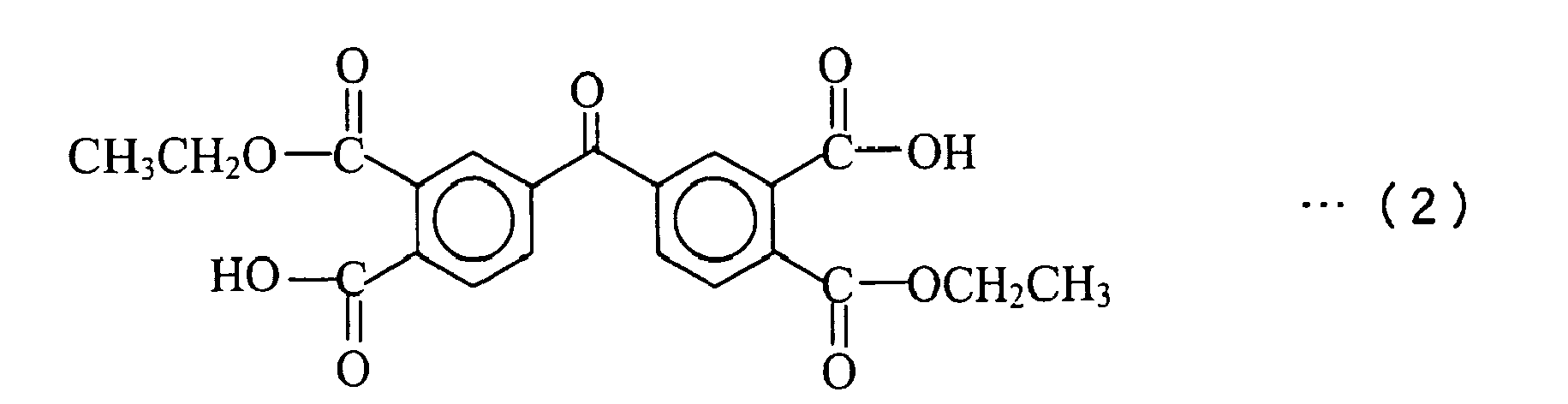


- The above-prepared negative electrode active material, graphite powder having an average particle size of 3 µm as a negative electrode conductive agent, and the just-described negative electrode binder precursor solution a1 were added to N-methyl-2-pyrrolidone (NMP) as a dispersion medium so that the weight ratio of the negative electrode active material powder, the negative electrode conductive agent powder, and the negative electrode binder (which was obtained by removing NMP from the negative electrode binder precursor solution a1 by drying and carrying out the polymerization reaction and the imidization reaction for the resultant) became 89.5:3.7:6.8. Thereafter, the mixture was kneaded to prepare a negative electrode mixture slurry.
- The just-described negative electrode mixture slurry was applied onto both sides of the negative electrode current collector in the air at 25°C. Thereafter, the resultant material was dried in the air at 120°C and pressure-rolled in the air at 25°C. Then, the resultant article was cut out into a rectangle shape with a length of 499 mm and a width of 35.7 mm, and thereafter was sintered at 420°C for 10 hours under an argon atmosphere, to thus prepare a member for preparing the negative electrode unit. It is noted that in the preparation of the member for preparing the electrode unit, there has been used a negative electrode current collector made of a 18 µm-thick copper alloy foil (C7025 alloy foil, containing 96.2 wt% of Cu, 3.0 wt% of Ni, 0.65 wt% of Si, and 0.15 wt% of Mg) that had been roughed on both sides so as to have a surface roughness Ra (defined by Japanese Industrial Standard (JIS) B 0601-1994) of 0.25 µm and a mean spacing of local peaks S (also defined by JIS B 0601-1994) of 0.85 µm. The amount of the negative electrode mixture layer on the negative electrode current collector was 5.6 mg/cm2, and the thickness of the negative electrode mixture layer was 56 µm.
- Onto one side of a film material made of polyimide (PI) having a thickness of 30 µm which was obtained by the dehydration and condensation of pyromellitic dianhydride and 4,4'-diaminophenyl ether, a peroxide-curing type silicone adhesive, SH4280 manufactured by Toray Dow Corning Silicone Co., Ltd. was applied. Thereafter, the resultant material was dried at 100°C for five minutes, and then was heat-treated at 180°C for five minutes to form a silicone adhesive layer having a thickness of 25 µm. Next, the resultant article was cut out into a shape with a width of 10 mm and a length of 36 mm to thus prepare an adhesive tape A.
- The just-described member for preparing negative electrode unit was cut out to prepare a rectangular negative electrode unit having a length of 239 mm and a width of 35.7 mm and a rectangular negative electrode unit having a length of 260 mm and a width of 35.7 mm. The adhesive tape A was adhered to both sides of the portion having a length of 4.5 mm and a width of 35.7 mm of adjacent end portions of both negative electrode units with the negative electrode units spaced at 1 mm, to prepare a negative electrode. Then, negative electrode current collector composed of a nickel plate having a thickness of 70 µm, a width of 3 mm, and a length of 45 mm was joined to the end portions of each negative electrode unit.
- Li2CO3 and CoCO3 were weighted so that the mole ratio of Li and Co became 1:1 and were mixed in a mortar. Thereafter, the mixture was sintered in an air atmosphere at 800°C for 24 hours and then pulverized to obtain powder of a lithium-cobalt composite oxide represented as LiCoO2 The powder of a lithium-cobalt composite oxide had an average particle size of 11 µm. The resultant powder of positive electrode active material had a BET specific surface area of 0.37 m2/g.
- The just-described LiCoO2 powder as a positive electrode active material, carbon material powder as a positive electrode conductive agent, and polyvinylidene fluoride as a positive electrode binder were added to N-methyl-2-pyrrolidone as a dispersion medium so that the weight ratio of the positive electrode active material, the positive electrode conductive agent, and the positive electrode binder became 95:2.5:2.5. Thereafter, the mixture was kneaded to prepare a positive electrode mixture slurry.
- The just-described positive electrode mixture slurry was applied onto both sides of the positive electrode current collector. Thereafter, the resultant material was dried in the air at 110°C and pressure-rolled. The amount of the positive electrode active material layer on the positive electrode current collector was 48 mg/cm2 in the portion where the active material layers were formed on both sides. The positive electrode had a thickness of 143 µm. As a positive electrode current collector, an aluminum (1085) foil having 15 µm thickness, 485 mm length, and 33.7 mm width was used.
- Next, a positive electrode current collector tub composed of an aluminum plate having 70 µm thickness, 3 mm width, and 45 mm length was connected to the end portion of the positive electrode.
- Lithium hexafluorophosphate (LiPF6) was dissolved at a concentration of 1.0 mole/L in a mixed solvent of 2:8 volume ratio of fluoroethylene carbonate (FEC) and methyl ethyl carbonate (MEC) under an argon atmosphere. Thereafter, 0.4 wt% of carbon dioxide gas was dissolved therein, to thus prepare a non-aqueous electrolyte solution.
- A sheet of positive electrode, a sheet of negative electrode, and two sheets of separators were wound around a winding core having a diameter of 4 mm with the positive and negative electrodes disposed facing each other via the separator interposed therebetween. Then, the winding core was removed to thus prepare an electrode assembly. The electrode assembly after removing of the winding core had a cylindrical shape having a diameter of 12.8 mm and a height of 37.7 mm. The separator used was a porous polyethylene film having a thickness of 20 µm, a length of 550 mm, a width of 37.7 mm, a penetration resistance of 350 g, and a porosity of 40%.
- The aforementioned cylindrical electrode assembly and the non-aqueous electrolyte solution were inserted into a cylindrical battery case made of SUS in a CO2 atmosphere at 25°C and 1 atm to fabricate Battery A1 according to Example 1. Battery A1 had a diameter of 14 mm and a height of 43 mm.
- In the example, Battery A2 was fabricated in the same manner as in Example 1, except that a different connecting member (adhesive tape B) was used and each length was set at L1=1 mm and L2=L3=7.5 mm.
- The resultant material obtained by mixing a butyl rubber, a petroleum resin manufactured by Maruzen Petrochemical Co., Ltd., MARUKACLEAR L, and a petroleum resin manufactured by Maruzen Petrochemical Co., Ltd., MARUKAREZ M-890A, in a weight ratio of 65:10:25, and diluting the mixture with toluene, was applied onto one side of the polyimide film material having a thickness of 30 µm which was also used in Battery A1. Thereafter, the resultant material was dried at 100°C for five minutes to form a rubber adhesive layer having a thickness of 25 µm. Then, the resultant article was cut out into a shape with a width of 16 mm and a length of 36 mm to thus prepare an adhesive tape B. In the example, a negative electrode was prepared using the adhesive tape B instead of adhesive tape A.
- In the example, Battery A3 was fabricated in the same manner as in Example 2, except that a different connecting member (adhesive tape C) was used.
- Butyl acrylate, acrylic acid, and benzoyl peroxide were mixed in the weight ratio of 65:10:25 and the mixture was solution copolymerized in toluene to obtain a polymer. The polymer and a polyisocyanate crosslinking agent manufactured by Nippon Polyurethane Industry Co., Ltd., Coronate L, were mixed in the weight ratio of 97:3 to prepare a solution. The resultant solution was applied onto one side of the film material having a thickness of 30 µm and made of polyphenylene sulfide (PPS). Thereafter, the resultant material was dried at 100°C for five minutes to form an acrylic adhesive layer having a thickness of 25 µm. Then, the resultant article was cut out into a shape with a width of 16 mm and a length of 36 mm to thus prepare an adhesive tape C. In the example, a negative electrode was prepared using the adhesive tape C instead of adhesive tape B.
- In the example, Battery A4 was fabricated in the same manner as in Example 3, except that an adhesive tape D, which was the same type of tape as the aforementioned adhesive tape C but had a width of 7 mm and a length of 36 mm, was used, and each length was set at L1=1 mm and L2=L3=3 mm.
- In the example, a lithium secondary battery A5 having the similar configuration to the lithium secondary battery according to the third embodiment was fabricated in the following manner. It is noted that Battery A5 was fabricated in substantially the same manner as in Example 1 other than the preparation of the negative and positive electrodes.
- The rectangular negative electrode having the similar configuration to the negative electrode unit of Battery A1 and having a length of 500 mm and a width of 35.7 mm was used. In the example, a negative electrode current collector tab composed of a nickel plate having a thickness of 70 µm, a width of 3 mm, and a length of 45 mm was joined to the end portions of the negative electrode in the longitudinal direction.
- A positive electrode unit having substantially the same configuration as the positive electrode of Battery A1 was prepared and was connected using the adhesive tape A, which was also used for preparing Battery A1, to prepare a positive electrode having the shape and dimension shown in
Fig. 9 . - In the example, Battery A6 was fabricated in the same manner as in Example 5, except that the adhesive tape B was used instead of the adhesive tape A and each length was set at L1=1 mm and L2=L3=7.5 mm.
- In the example, Battery A7 was fabricated in the same manner as in Example 6, except that the adhesive tape C was used instead of the adhesive tape B.
- In the example, Battery A8 was fabricated in the same manner as in Example 5, except that the adhesive tape D was used instead of the adhesive tape B and each length was set at L1=1 mm and L2=L3=3 mm.
- In the example, Battery A9 was fabricated in the same manner as in Example 5 except that another positive electrode was used. In the example, a positive electrode shown in
Fig. 11 was prepared in the following manner. - A positive electrode unit having substantially the same configuration as the positive electrode of Battery A1 was prepared and was connected using the adhesive tape A, which was also used for preparing Battery A1, to prepare a positive electrode having the shape and dimension shown in
Fig. 11 . - Battery B1 1 was fabricated in the same manner as in Example 1 except that the negative electrode similar to the negative electrode which was used with Battery A5 was used.
- The mechanical property of two adhesive tapes, which were used in Batteries A1 to A9 as the connecting member, was measured by a tensile test under the following conditions. The obtained stress-strain curve provides tensile strength, tensile modulus (gradient of the curved portion from the strain of zero), and elongation per width of 1 mm.
-
- . Test sample: the resultant material obtained by adhering two adhesive tapes having a width of 15 mm and a length of 140 mm via an adhesive portion
- . Size of test sample: a width of 15 mm and a length of 140 mm
- . Grabbed amount of sample during tension measurement: a width of 15 mm and a length of 20 mm from each of both ends
- . Device: desktop load measuring device 1310N manufactured by AIKOH ENGINEERING CO., LTD.
- . Tension rate: 5 mm/sec.
- The mechanical property of the portion of a sheet of negative electrode unit among the aforementioned Batteries A1 to A9 and B1 (Batteries A5 to A9 and B1 are negative electrodes), on which the negative electrode active material layer is provided, was measured by a tensile test under the following conditions. The obtained stress-strain curve provides tensile strength, tensile modulus (gradient of the curved portion from the strain of zero), and elongation per width of 1 mm.
-
- . Test sample: the piece obtained by cutting out the applied portion into a rectangular shape with a width of 15 mm and a length of 140 mm
- . Grabbed amount of sample during tension measurement: a width of 15 mm and a length of 20 mm from each of both ends
- . Device: desktop load measuring device 1310N manufactured by AIKOH ENGINEERING CO., LTD.
- . Tension rate: 5 mm/sec.
- The mechanical property of the portion of a positive electrode among the aforementioned Batteries A1 to A9 and B1 (each of Batteries A5 to A9 and B1 is a sheet of positive electrode unit), on which the positive electrode active material layer are provided on both sides, was measured by a tensile test under the following conditions. The obtained stress-strain curve provides tensile strength, tensile modulus (gradient of the curved portion from the strain of zero), and elongation per width of 1 mm.
-
- . Test sample: the piece obtained by cutting out the applied portion into a rectangular shape with a width of 15 mm and a length of 140 mm
- . Grabbed amount of sample during tension measurement: a width of 15 mm and a length of 20 mm from each of both ends
- . Device: desktop load measuring device 1310N manufactured by AIKOH ENGINEERING CO., LTD.
- . Tension rate: 5 mm/sec.
- As shown in
Fig. 15 , the two electrode units were connected via the two adhesive tapes to prepare a sample. Using the sample, a tensile test was carried out under the following conditions to measure the adhesive strength of each adhesive tape. It is noted that the adhesive strength refers to a tensile force per width of 1 mm at the time of the occurrence of the peeling off of either one of two adhering portions between the electrode unit and the adhesive tape. -
- . Size of test sample: a width of 15 mm and a length of 140 mm
- . Grabbed amount of sample during tension measurement: a width of 15 mm and a length of 20 mm from each of both ends
- . Device: desktop load measuring device 1310N manufactured by AIKOH ENGINEERING CO., LTD.
- . Tension rate: 5 mm/sec.
- The aforementioned Batteries A1 to A9 and B1 were evaluated in terms of charge-discharge cycle performance under the following charge-discharge cycle conditions.
-
- . Charge for the First Cycle
Each of the batteries was charged at a constant current of 45 mA for 4 hours, thereafter charged at a constant current of 180 mA until the battery voltage reached 4.2 V, and further charged at a constant voltage of 4.2 V until the current value reached 45 mA. - . Discharge for the First Cycle
Each of the batteries was discharged at a constant current of 180 mA until the battery voltage reached 2.75 V. - . Charge for the Second Cycle Onward
Each of the batteries was charged at a constant current of 450 mA until the battery voltage reached 4.2 V and thereafter charged at a constant voltage of 4.2 V until the current value reached 45 mA. - . Discharge for the Second Cycle Onward
Each of the batteries was discharged at a constant current of 900 mA until the battery voltage reached 2.75 V. - In addition, the charge-discharge cycle life, which is defined as the number of cycles at which the capacity retention ratio (the value obtained by dividing the discharge capacity at the nth cycle by the discharge capacity at the first cycle) reaches 85%, was calculated.
- The results of the above tests are shown in Tables 1 and 2.
Table 1 Battery Connecting Member Negative Electrode Unit (Negative Electrode) Positive Electrode Unit (Positive Electrode) Connecting Portion Resin Sheet Adhesive Tensile Strength (N/mm) Tensile Modulus (N/mm) Elongation (%) Tensile Strength (N/mm) Tensile Modulus (N/mm) Elongation (%) Tensile Strength (N/mm) Tensile Modulus (N/mm) Elongation (%) Electrode Adhesive Strength (N/mm) Battery A1 PI Silicone 7.8 82 51 7.3 1600 6.4 2.5 670 3.1 Negative Electrode 6.6 Battery A2 PI Rubber 7.6 94 53 7.3 1600 6.4 2.5 670 3.1 Negative Electrode 61 Battery A3 PPS Acrylic 5.3 67 56 7.3 1600 6.4 2.5 670 3.1 Negative Electrode 6 3 Battery A4 PPS Acrylic 5.1 65 52 7.3 1600 6.4 2.5 670 3.1 Negative Electrode 5.7 Battery A5 PI Silicon 7.8 82 51 7.3 1600 6.4 2.5 670 3.1 Positive Electrode *1)
(≥2.5)Battery A6 P1 Rubber 7 6 94 53 7.3 1600 6.4 2.5 670 3.1 Positive Electrode *1)
(≥2 5)Battery A7 PPS Acrylic 5 3 67 56 7.3 1600 6.4 2.5 670 3.1 Positive Electrode *1)
(≥2.5)Battery A8 PPS Acrylic 5.1 65 52 7.3 1600 6.4 2.5 670 3.1 Positive electrode *1)
(≥2.5)Battery A9 PI Silicone 7.8 82 51 7.3 1600 6.4 2.5 670 3.1 Positive Electrode *1)
(≥2.5)Battery B1 Not Applied Not Applied ― ― ― 7.3 1600 6.4 2.5 5 670 3.1 Not Applied ― *1) The portion to which the electrode was not applied was early broken Table 2 Battery Battery Shape Electrode Unit Connecting Member Connecting Portion Cycle Life Electrode Number Tensile Modulus (N/mm) Resin Sheet Adhesive Tensile Modulus (N/mm) Adhesive Strength (N/mm) Battery A1 Cylindrical Negative Electrode 2 1600 PI Silicone 82 6. 6 131 Battery A2 Cylindrical Negative Electrode 2 1600 PI Rubber 94 6.1 119 Battery A3 Cylindrical Negative Electrode 2 1600 PPS Acrylic 67 6.3 137 Battery A4 Cylindrical Negative Electrode 2 1600 PPS Acrylic 65 5.7 139 Battery A5 Cylindrical Positive Electrode 2 670 PI Silicone 82 *1)
(≥25)122 Battery A6 Cylindrical Positive Electrode 2 670 PI Rubber 94 *1)
(≥2 5)112 Battery A7 Cylindrical Electrode 2 670 PPS Acrylic 67 *1)
(≥ 25)128 Battery A8 Cylindrical Positive Electrode 2 670 PPS Acrylic 65 *1)
(≥ 2 5)128 Battery A9 Cylindrical Positive Electrode 3 670 PI Silicone 75 *1)
(≥ 2 5)135 Battery B1 cylindrical Not Applied ― ― Not Applied Not Applied ― ― 102 *1) The portion to which the electrode was not applied was early broken - As shown in above Tables 1 and 2, Batteries A1 to A9 of which at least one of the positive and negative electrodes is composed of the plurality of electrode units exhibited more excellent cycle life than Battery B1 of which each of positive and negative electrodes is integrally formed. From this result, it is understood that the configuration in which at least one of the positive and negative electrodes is composed of the plurality of electrode units can achieve excellent charge-discharge cycle life.
- Moreover, by comparing among Batteries A1 to A4 and among Batteries A5 to A8, it is understood that the lower the tensile modulus of the connecting member is, the longer the charge-discharge cycle life becomes. Particularly, it is understood that when the tensile modulus of the connecting member is 90 N/mm or less, the longer charge-discharge cycle life can be achieved.
- In addition, by comparing between Batteries A1 to A4 and Batteries A5 to A8, it is understood that the effect of improving the charge-discharge cycle life can be made more effective in the case of dividing the negative electrode into the plurality of electrode units, rather than the case of dividing the positive electrode into the plurality of electrode units.
- Furthermore, by comparing between Batteries A5 and A9, it is understood that the larger the number of electrode units constituting the negative or positive electrode is, the more excellent the charge-discharge cycle life is.
- Next, the inventors had examined the case where the battery case had a flat shape.
- In the example, a lithium secondary battery C 1 having the similar configuration to the lithium secondary battery 1 according to the fifth embodiment was fabricated.
- Specifically, a cylindrical electrode assembly was prepared using the positive and negative electrodes and the separator which were used in Example 1, and was pressed on to obtain a flat-shaped electrode assembly. Then, the same type of electrolyte solution as used in Example 1 and the aforementioned flat-shaped electrode assembly were inserted into an aluminum laminate battery case in a CO2 atmosphere at 25°C and 1 atm to fabricate flat-shaped Battery C1.
- Battery C2 was fabricated in the same manner as in Example 10 except that the positive and negative electrodes of Example 2 were used.
- Battery C3 was fabricated in the same manner as in Example 10 except that the positive and negative electrodes of Example 3 were used.
- Battery C4 was fabricated in the same manner as in Example 10 except that the positive and negative electrodes of Example 4 were used.
- Battery C5 was fabricated in the same manner as in Example 10 except that the positive and negative electrodes of Example 5 were used.
- Battery C6 was fabricated in the same manner as in Example 10 except that the positive and negative electrodes of Example 6 were used.
- Battery C7 was fabricated in the same manner as in Example 10 except that the positive and negative electrodes of Example 7 were used.
- Battery C8 was fabricated in the same manner as in Example 10 except that the positive and negative electrodes of Example 8 were used.
- Battery C9 was fabricated in the same manner as in Example 10 except that the positive and negative electrodes of Example 9 were used.
- Battery D1 was fabricated in the same manner as in Example 10 except that the positive and negative electrodes of Comparative Example 1 were used.
- The charge-discharge cycle life for each of Batteries C1 to C9 and D1 was also obtained in the same manner. The results are shown in Table 3.
Table 3 Battery Battery Shape Electrode Unit Connecting Member Connecting Portion Cycle Life Electrode Number Tensile Modulus (N/mm) Resin Sheet Adhesive Tensile Modulus (N/mm) Adhesive Strength (N/mm) Battery C1 Flat-Shaped Negative Electrode 2 1600 PI Silicone 82 6. 6 110 Battery C2 Flat-Shaped Negative Electrode 2 1600 PI Rubber 94 6.1 109 Battery C3 Flat-Shaped Negative Electrode 2 1600 PPS Acrylic 67 6. 3 114 Battery C4 Flat-Shaped Negative Electrode 2 1600 PPS Acrylic 65 5.7 111 Battery C5 Flat-Shaped Positive Electrode 2 670 PI Silicone 82 *1)
(≥ 2 5)108 Battery C6 Flat-Shaped Positive Electrode 2 670 PI Rubber 94 *1)
(≥25)107 Battery C7 Flat-Shaped Positive Electrode 2 670 PPS Acrylic 67 *1)
(≥2 5)109 Battery C8 Flat-Shaped Positive Electrode 2 670 PPS Acrylic 65 *1)
(≥25)109 Battery C9 Flat-Shaped Positive Electrode 3 670 PI Silicone 75 *1)
(≥2 5)111 Battery D1 Flat-Shaped Not Applied ― ― Not Applied Not Applied ― ― 99 *1) The portion to which the electrode was not applied was early broken. - The results shown in Table 3 clearly demonstrate that, even when the battery case has a flat shape, Batteries C1 to C9 each of which at least one of positive and negative electrodes was divided into the plurality of electrode units exhibited more excellent charge-discharge cycle life than Battery D1 of which both of positive and negative electrodes were integrally formed. From the results, it is understood that the aforementioned effect of improving the charge-discharge cycle performance can be obtained regardless of the shape of the battery case.
- However, as apparent from the comparison between Batteries A1 to A9 and Batteries C1 to C9, it is understood that the cylindrical batteries have a greater effect of improving the charge-discharge cycle life than the flat-shaped batteries. From the results, it will be particularly advantageous to divide at least one of positive and negative electrodes into the plurality of electrode units in the lithium secondary battery using the cylindrical battery case.
- Next, an experiment for considering the relationship between the kinds of the positive electrode active material and the cycle life was conducted.
- Battery E1 was fabricated in the same manner as in Example 10 except that the positive electrode prepared under the following conditions was used.
- LiOH and a composite hydroxide in which nickel was principal component (Ni0.80Co0.17Al0.03(OH)2) were mixed using a mortar to provide the mole ratio of 1.05:1. Thereafter, the mixture was sintered in an air atmosphere at 720°C for 20 hours and then pulverized to obtain powder of a lithium-nickel-cobalt-aluminum composite oxide represented as Li1.05Ni0.80Co0.17Al0.03O2 having an average particle size of 10 µm. In the example, the lithium-nickel-cobalt-aluminum composite oxide was used as the positive electrode active material. It is noted that the resultant powder of lithium-nickel-cobalt-aluminum composite oxide had a BET specific surface area of 0.39 m2/g.
- The above-prepared powder of positive electrode active material, carbon material powder as a positive electrode conductive agent, and polyvinylidene fluoride as a positive electrode binder were added to NMP as a dispersion medium so that the weight ratio of the active material, the conductive agent, and the binder became 95:2.5:2.5. Thereafter, the mixture was kneaded to prepare a positive electrode mixture slurry.
- The positive electrode mixture slurry was applied to both sides of an aluminum foil having 15 µm thickness, 402 mm length, and 50 mm width as the positive electrode current collector so that the applied portion had 340 mm length and 50 mm width on the front surface and 270 mm length and 50 mm width on the back surface. Thereafter, the resultant material was dried and pressure-rolled. The amount of the active material layer on the current collector and the thickness of the positive electrode were 36.6 mg/cm2 and 117 µm, respectively, in the portion on which the active material layer was formed on both sides.
- Then, an aluminum plate serving as a positive electrode current collector tab was connected to an end portion of the positive electrode to which the positive electrode active material layer was not applied.
- Battery F1 was fabricated in the same manner as in Comparative Example 2 except that the positive electrode prepared in Example 19 was used.
- The charge-discharge cycle life of each of Battery E1 fabricated in Example 19 and Battery F1 fabricated in Comparative Example 3 was evaluated in the same manner as the above evaluation method. The results are shown in Table 4 in conjunction with the evaluation results for Batteries C1 and D1.
Battery Battery Shape Positive Electrode Electrode Unit Connecting Member Connecting Portion Cycle Life Electrode Number Tensile Modulus (N/mm) Resin Sheet Adhesive Tensile Modulus (N/mm) Adhesive Strength (N/mm) Battery E1 Flat-Shaped Li1 05Ni 0 80Co0 17Al 0 0302 Negative Electrode 2 1600 PI Silicone 82 6. 6 118 +27 Battery F1 Flat-Shaped Li1 05Ni0 80Co0 17Al0 0302 Not Applied ― ― Not Applied Not Applied ― ― 91 Battery C1 Flat-Shaped LiCo02 Negative Electrode 2 1600 PI Silicone 82 6. 1 110 +11 Battery D1 Flat-Shaped LiCo02 Not Applied ― ― Not Applied Not Applied ― ― 99 - As shown in Table 4, Battery E1 of which at least one of positive and negative electrodes was divided into the plurality of electrode units had more excellent cycle life than Battery F1 of which each of positive and negative electrodes was integrally formed. From the results, it is understood that the cycle life can be increased by dividing at least one of the positive and negative electrodes into the plurality of electrode units even when the lithium-nickel-cobalt-aluminum composite oxide was used as a positive electrode active material.
- As comparing Batteries D1 and F1 of which positive and negative electrodes were not divided into the plurality of electrode units, Battery D1 which did not contain Ni as a positive electrode active material had a better cycle life than Battery F1 which contained Ni as a positive electrode active material.
- On the other hand, as comparing Batteries C1 and E1 of which at least one of the positive and negative electrodes was divided into the plurality of electrode units, Battery E1 which contained Ni as a positive electrode active material had a better cycle life than Battery C 1 which did not contain Ni as a positive electrode active material.
- Moreover, Battery C1 of which at least one of the positive and negative electrodes was divided into the plurality of electrode units had longer cycle life by 11 cycles than Battery D1 of which each of positive and negative electrodes were integrally formed. On the other hand, Battery E1 of which at least one of the positive and negative electrodes was divided into the plurality of electrode units had longer cycle life by 27 cycles than Battery F1 of which each of positive and negative electrodes was integrally formed.
- From the results, it is understood that the greater effect of improving the cycle life, which is caused by dividing at least one of the positive and negative electrodes into the plurality of electrode units, can be achieved when the lithium-nickel-cobalt-aluminum composite oxide was used as a positive electrode active material, than when lithium-cobalt composite oxide was used as a positive electrode active material.
Claims (13)
- A lithium secondary battery comprising:an electrode assembly which is made by winding a negative electrode containing a negative electrode active material that is alloyed with lithium, a positive electrode, and a separator interposed between the negative and positive electrodes; anda non-aqueous electrolyte which is impregnated in the electrode assembly,
whereinat least one of the negative and positive electrodes is divided into a plurality of electrode units which are arranged at spaces for each other along the winding direction. - The lithium secondary battery according to Claim 1, further comprising a connecting member which connects the adjacent electrode units.
- The lithium secondary battery according to Claim 2, wherein tensile modulus of the connecting member is lower than tensile modulus of the electrode units.
- The lithium secondary battery according to Claim 2 or 3, wherein the tensile modulus of the connecting member is 90 N/mm or less.
- The lithium secondary battery according to any one of Claims 1 to 4, further comprising tabs which are electrically connected to each end portion of the plurality of electrode units, wherein
the plurality of electrode units are arranged such that the ends to which the tabs of the electrode units are connected are not adjacent to each other in the winding direction. - The lithium secondary battery according to any one of Claims 2 to 5, wherein the connecting member has a first tape which is adhered or bonded to one surface of the electrode unit, and a second tape which is adhered or bonded to the other surface of the electrode unit.
- The lithium secondary battery according to any one of Claims 2 to 6, wherein the connecting member is made of resin.
- The lithium secondary battery according to any one of Claims 1 to 7, wherein the negative electrode is divided into the plurality of electrode units.
- The lithium secondary battery according to Claim 8, wherein each of the negative and positive electrodes is divided into the plurality of electrode units.
- The lithium secondary battery according to any one of Claims 1 to 9, further comprising a cylindrical battery case into which the electrode assembly is put.
- The lithium secondary battery according to any one of Claims 1 to 10, wherein the number of the electrode units in the electrode which is divided into the plurality of electrode units, of the negative and positive electrodes, is four or less.
- The lithium secondary battery according to any one of Claims 1 to 11, wherein the negative electrode active material is at least one of silicon and silicon alloy.
- The lithium secondary battery according to any one of Claims 1 to 12, wherein the positive electrode contains a lithium-transition metal composite oxide represented by the chemical formula, LiaNi(1-b-c)CobAlcO2, where 0<a≤1.1, 0.1≤b≤0.3, and 0.03≤c≤0.1, as a positive electrode active material.
Applications Claiming Priority (2)
| Application Number | Priority Date | Filing Date | Title |
|---|---|---|---|
| JP2010048148 | 2010-03-04 | ||
| JP2010120724A JP2011204660A (en) | 2010-03-04 | 2010-05-26 | Lithium secondary battery |
Publications (1)
| Publication Number | Publication Date |
|---|---|
| EP2365572A2 true EP2365572A2 (en) | 2011-09-14 |
Family
ID=44148944
Family Applications (1)
| Application Number | Title | Priority Date | Filing Date |
|---|---|---|---|
| EP11001795A Withdrawn EP2365572A2 (en) | 2010-03-04 | 2011-03-03 | Lithium secondary battery |
Country Status (4)
| Country | Link |
|---|---|
| US (1) | US20110217577A1 (en) |
| EP (1) | EP2365572A2 (en) |
| JP (1) | JP2011204660A (en) |
| CN (1) | CN102195095A (en) |
Families Citing this family (18)
| Publication number | Priority date | Publication date | Assignee | Title |
|---|---|---|---|---|
| JP5741932B2 (en) * | 2011-06-01 | 2015-07-01 | 住友金属鉱山株式会社 | Transition metal composite hydroxide as a precursor of a positive electrode active material for a non-aqueous electrolyte secondary battery, a method for producing the same, and a method for producing a positive electrode active material for a non-aqueous electrolyte secondary battery |
| KR101911433B1 (en) * | 2012-12-14 | 2018-10-24 | 삼성전자주식회사 | Stack type battery |
| WO2015003725A1 (en) | 2013-07-09 | 2015-01-15 | Friedrich-Schiller-Universität Jena | Electroactive polymers, manufacturing process thereof, electrode and use thereof |
| JP2017045789A (en) * | 2015-08-25 | 2017-03-02 | アイシン精機株式会社 | Lithium ion capacitor |
| US10468667B2 (en) | 2015-11-20 | 2019-11-05 | Sanyo Electric Co., Ltd. | Electrode sheet for use in power storage device and power storage device including electrode sheet |
| EP3316354B1 (en) * | 2016-10-28 | 2019-08-14 | Lumimodule Optical Corporation | Secondary battery manufactured by arrangement simultaneously possessing advantages specific to winding process and advantages specific to stacking process |
| WO2019003641A1 (en) * | 2017-06-30 | 2019-01-03 | パナソニックIpマネジメント株式会社 | Non-aqueous electrolyte secondary battery |
| JP6973489B2 (en) | 2017-08-21 | 2021-12-01 | 株式会社村田製作所 | Batteries, battery packs, electronics, electric vehicles, power storage devices and power systems |
| JP7122581B2 (en) * | 2017-12-25 | 2022-08-22 | パナソニックIpマネジメント株式会社 | secondary battery |
| WO2019176422A1 (en) * | 2018-03-13 | 2019-09-19 | 三洋電機株式会社 | Secondary battery |
| JP7112860B2 (en) * | 2018-03-14 | 2022-08-04 | セイコーインスツル株式会社 | Coin type non-aqueous electrolyte secondary battery for reflow mounting |
| JP7093278B2 (en) * | 2018-09-19 | 2022-06-29 | リンテック株式会社 | Lithium ion battery |
| WO2022015101A1 (en) | 2020-07-16 | 2022-01-20 | 주식회사 엘지에너지솔루션 | Electrode assembly |
| US20230378438A1 (en) * | 2020-09-30 | 2023-11-23 | Panasonic Intellectual Property Management Co., Ltd. | Nonaqueous electrolyte secondary battery |
| CN114094167B (en) * | 2021-11-23 | 2023-12-19 | 珠海冠宇电池股份有限公司 | a battery |
| JP2024526225A (en) | 2021-11-23 | 2024-07-17 | 珠海冠宇電池股分有限公司 | battery |
| CN116936720A (en) * | 2022-03-31 | 2023-10-24 | 宁德时代新能源科技股份有限公司 | Electrode assembly, battery cell, battery, electric equipment, winding equipment and method |
| CN119968737B (en) * | 2023-01-18 | 2025-11-14 | 宁德时代新能源科技股份有限公司 | Cathode electrode, anode electrode, battery cell, battery and electrical device |
Citations (2)
| Publication number | Priority date | Publication date | Assignee | Title |
|---|---|---|---|---|
| JP2002260637A (en) | 2000-09-01 | 2002-09-13 | Sanyo Electric Co Ltd | Negative electrode for lithium secondary battery, and its manufacturing method |
| JP2008124036A (en) | 2008-01-10 | 2008-05-29 | Sanyo Electric Co Ltd | Negative electrode for lithium secondary battery and lithium secondary battery |
Family Cites Families (4)
| Publication number | Priority date | Publication date | Assignee | Title |
|---|---|---|---|---|
| JPH07249405A (en) * | 1994-03-10 | 1995-09-26 | Haibaru:Kk | Battery |
| US6468693B1 (en) * | 1999-07-29 | 2002-10-22 | Kabushiki Kaisha Toshiba | Nonaqueous electrolyte secondary battery |
| WO2002021616A1 (en) * | 2000-09-01 | 2002-03-14 | Sanyo Electric Co., Ltd. | Negative electrode for lithium secondary cell and method for producing the same |
| WO2005101549A1 (en) * | 2004-04-01 | 2005-10-27 | Sumitomo Electric Industries Ltd. | Negative electrode member for secondary lithium battery and process for producing the same |
-
2010
- 2010-05-26 JP JP2010120724A patent/JP2011204660A/en not_active Withdrawn
-
2011
- 2011-03-03 EP EP11001795A patent/EP2365572A2/en not_active Withdrawn
- 2011-03-04 CN CN2011100526831A patent/CN102195095A/en active Pending
- 2011-03-04 US US13/040,707 patent/US20110217577A1/en not_active Abandoned
Patent Citations (2)
| Publication number | Priority date | Publication date | Assignee | Title |
|---|---|---|---|---|
| JP2002260637A (en) | 2000-09-01 | 2002-09-13 | Sanyo Electric Co Ltd | Negative electrode for lithium secondary battery, and its manufacturing method |
| JP2008124036A (en) | 2008-01-10 | 2008-05-29 | Sanyo Electric Co Ltd | Negative electrode for lithium secondary battery and lithium secondary battery |
Also Published As
| Publication number | Publication date |
|---|---|
| JP2011204660A (en) | 2011-10-13 |
| US20110217577A1 (en) | 2011-09-08 |
| CN102195095A (en) | 2011-09-21 |
Similar Documents
| Publication | Publication Date | Title |
|---|---|---|
| US20110217577A1 (en) | Lithium secondary battery | |
| KR101389609B1 (en) | Lithium secondary battery and use thereof | |
| KR100732803B1 (en) | Lithium ion secondary battery | |
| CN105591058B (en) | Heat resisting micro pore film and battery diaphragm | |
| CN1663065B (en) | Negative electrode for lithium secondary cell and lithium secondary cell | |
| KR101601690B1 (en) | METHOD FOR MANUFACTURING ELECTRODE COMPRISING POROUS PROTECTIVE FILM, ELECTRODE WITH NON-AQUEOUS ELECTROLYTE SECONDARY BATTERY, | |
| US20110206962A1 (en) | Nonaqueous electrolyte secondary battery and method for manufacturing the same | |
| EP2903063A1 (en) | Collector, electrode structure, nonaqueous electrolyte battery, conductive filler, and electricity storage component | |
| CN111448687A (en) | Secondary battery, insulating member, and positive electrode lead | |
| JP2006155959A (en) | Negative electrode and battery | |
| US20100330405A1 (en) | Nonaqueous electrolyte secondary battery | |
| JP7776629B2 (en) | Lithium secondary battery | |
| JP2005100959A (en) | Negative electrode for nonaqueous electrolyte secondary battery, method for producing the same, and nonaqueous electrolyte secondary battery | |
| JP2002093404A (en) | Flat battery | |
| KR102823289B1 (en) | Electrode current collector and secondary battery | |
| JP2007012598A (en) | Nonaqueous electrolyte secondary battery and battery module | |
| CN117637989B (en) | Electrode sheet, electrode assembly and battery | |
| CN1185861A (en) | Non-aqueous electrolyte secondary battery | |
| US20050084753A1 (en) | Electrode assembly with separated support tapes in secondary battery | |
| KR20200131791A (en) | Nonaqueous electrolyte secondary battery | |
| JP7628503B2 (en) | High power, extended temperature range, and overcharge-resistant rechargeable battery cells and battery packs | |
| US9048491B2 (en) | Lithium-ion secondary battery | |
| CN112805347A (en) | Insulating tapes, pole pieces and electrochemical devices | |
| EP4593151A1 (en) | Lithium secondary battery | |
| CN100492720C (en) | Lithium ion secondary battery |
Legal Events
| Date | Code | Title | Description |
|---|---|---|---|
| PUAI | Public reference made under article 153(3) epc to a published international application that has entered the european phase |
Free format text: ORIGINAL CODE: 0009012 |
|
| AK | Designated contracting states |
Kind code of ref document: A2 Designated state(s): AL AT BE BG CH CY CZ DE DK EE ES FI FR GB GR HR HU IE IS IT LI LT LU LV MC MK MT NL NO PL PT RO RS SE SI SK SM TR |
|
| AX | Request for extension of the european patent |
Extension state: BA ME |
|
| STAA | Information on the status of an ep patent application or granted ep patent |
Free format text: STATUS: THE APPLICATION HAS BEEN WITHDRAWN |
|
| 18W | Application withdrawn |
Effective date: 20130206 |