EP2365298A2 - Dynamic-adaptive vapor reduction system in a mass flowmeter and corresponding method - Google Patents
Dynamic-adaptive vapor reduction system in a mass flowmeter and corresponding method Download PDFInfo
- Publication number
- EP2365298A2 EP2365298A2 EP20110157397 EP11157397A EP2365298A2 EP 2365298 A2 EP2365298 A2 EP 2365298A2 EP 20110157397 EP20110157397 EP 20110157397 EP 11157397 A EP11157397 A EP 11157397A EP 2365298 A2 EP2365298 A2 EP 2365298A2
- Authority
- EP
- European Patent Office
- Prior art keywords
- mass flow
- flow meter
- vapor
- fluid
- fluid flowing
- Prior art date
- Legal status (The legal status is an assumption and is not a legal conclusion. Google has not performed a legal analysis and makes no representation as to the accuracy of the status listed.)
- Granted
Links
Images


Classifications
-
- F—MECHANICAL ENGINEERING; LIGHTING; HEATING; WEAPONS; BLASTING
- F17—STORING OR DISTRIBUTING GASES OR LIQUIDS
- F17D—PIPE-LINE SYSTEMS; PIPE-LINES
- F17D1/00—Pipe-line systems
- F17D1/20—Arrangements or systems of devices for influencing or altering dynamic characteristics of the systems, e.g. for damping pulsations caused by opening or closing of valves
-
- F—MECHANICAL ENGINEERING; LIGHTING; HEATING; WEAPONS; BLASTING
- F17—STORING OR DISTRIBUTING GASES OR LIQUIDS
- F17D—PIPE-LINE SYSTEMS; PIPE-LINES
- F17D1/00—Pipe-line systems
- F17D1/005—Pipe-line systems for a two-phase gas-liquid flow
-
- G—PHYSICS
- G01—MEASURING; TESTING
- G01F—MEASURING VOLUME, VOLUME FLOW, MASS FLOW OR LIQUID LEVEL; METERING BY VOLUME
- G01F1/00—Measuring the volume flow or mass flow of fluid or fluent solid material wherein the fluid passes through a meter in a continuous flow
- G01F1/76—Devices for measuring mass flow of a fluid or a fluent solid material
- G01F1/78—Direct mass flowmeters
- G01F1/80—Direct mass flowmeters operating by measuring pressure, force, momentum, or frequency of a fluid flow to which a rotational movement has been imparted
- G01F1/84—Coriolis or gyroscopic mass flowmeters
- G01F1/8409—Coriolis or gyroscopic mass flowmeters constructional details
- G01F1/8413—Coriolis or gyroscopic mass flowmeters constructional details means for influencing the flowmeter's motional or vibrational behaviour, e.g., conduit support or fixing means, or conduit attachments
-
- G—PHYSICS
- G01—MEASURING; TESTING
- G01F—MEASURING VOLUME, VOLUME FLOW, MASS FLOW OR LIQUID LEVEL; METERING BY VOLUME
- G01F1/00—Measuring the volume flow or mass flow of fluid or fluent solid material wherein the fluid passes through a meter in a continuous flow
- G01F1/76—Devices for measuring mass flow of a fluid or a fluent solid material
- G01F1/78—Direct mass flowmeters
- G01F1/80—Direct mass flowmeters operating by measuring pressure, force, momentum, or frequency of a fluid flow to which a rotational movement has been imparted
- G01F1/84—Coriolis or gyroscopic mass flowmeters
- G01F1/845—Coriolis or gyroscopic mass flowmeters arrangements of measuring means, e.g., of measuring conduits
- G01F1/8468—Coriolis or gyroscopic mass flowmeters arrangements of measuring means, e.g., of measuring conduits vibrating measuring conduits
- G01F1/8472—Coriolis or gyroscopic mass flowmeters arrangements of measuring means, e.g., of measuring conduits vibrating measuring conduits having curved measuring conduits, i.e. whereby the measuring conduits' curved center line lies within a plane
-
- G—PHYSICS
- G01—MEASURING; TESTING
- G01F—MEASURING VOLUME, VOLUME FLOW, MASS FLOW OR LIQUID LEVEL; METERING BY VOLUME
- G01F15/00—Details of, or accessories for, apparatus of groups G01F1/00 - G01F13/00 insofar as such details or appliances are not adapted to particular types of such apparatus
- G01F15/001—Means for regulating or setting the meter for a predetermined quantity
-
- G—PHYSICS
- G01—MEASURING; TESTING
- G01F—MEASURING VOLUME, VOLUME FLOW, MASS FLOW OR LIQUID LEVEL; METERING BY VOLUME
- G01F15/00—Details of, or accessories for, apparatus of groups G01F1/00 - G01F13/00 insofar as such details or appliances are not adapted to particular types of such apparatus
- G01F15/005—Valves
-
- G—PHYSICS
- G01—MEASURING; TESTING
- G01F—MEASURING VOLUME, VOLUME FLOW, MASS FLOW OR LIQUID LEVEL; METERING BY VOLUME
- G01F15/00—Details of, or accessories for, apparatus of groups G01F1/00 - G01F13/00 insofar as such details or appliances are not adapted to particular types of such apparatus
- G01F15/02—Compensating or correcting for variations in pressure, density or temperature
- G01F15/026—Compensating or correcting for variations in pressure, density or temperature using means to maintain zero differential pressure across the motor
-
- G—PHYSICS
- G01—MEASURING; TESTING
- G01N—INVESTIGATING OR ANALYSING MATERIALS BY DETERMINING THEIR CHEMICAL OR PHYSICAL PROPERTIES
- G01N9/00—Investigating density or specific gravity of materials; Analysing materials by determining density or specific gravity
- G01N9/002—Investigating density or specific gravity of materials; Analysing materials by determining density or specific gravity using variation of the resonant frequency of an element vibrating in contact with the material submitted to analysis
-
- G—PHYSICS
- G01—MEASURING; TESTING
- G01N—INVESTIGATING OR ANALYSING MATERIALS BY DETERMINING THEIR CHEMICAL OR PHYSICAL PROPERTIES
- G01N9/00—Investigating density or specific gravity of materials; Analysing materials by determining density or specific gravity
- G01N9/32—Investigating density or specific gravity of materials; Analysing materials by determining density or specific gravity by using flow properties of fluids, e.g. flow through tubes or apertures
-
- Y—GENERAL TAGGING OF NEW TECHNOLOGICAL DEVELOPMENTS; GENERAL TAGGING OF CROSS-SECTIONAL TECHNOLOGIES SPANNING OVER SEVERAL SECTIONS OF THE IPC; TECHNICAL SUBJECTS COVERED BY FORMER USPC CROSS-REFERENCE ART COLLECTIONS [XRACs] AND DIGESTS
- Y10—TECHNICAL SUBJECTS COVERED BY FORMER USPC
- Y10T—TECHNICAL SUBJECTS COVERED BY FORMER US CLASSIFICATION
- Y10T137/00—Fluid handling
- Y10T137/0318—Processes
- Y10T137/0324—With control of flow by a condition or characteristic of a fluid
- Y10T137/0329—Mixing of plural fluids of diverse characteristics or conditions
- Y10T137/0335—Controlled by consistency of mixture
-
- Y—GENERAL TAGGING OF NEW TECHNOLOGICAL DEVELOPMENTS; GENERAL TAGGING OF CROSS-SECTIONAL TECHNOLOGIES SPANNING OVER SEVERAL SECTIONS OF THE IPC; TECHNICAL SUBJECTS COVERED BY FORMER USPC CROSS-REFERENCE ART COLLECTIONS [XRACs] AND DIGESTS
- Y10—TECHNICAL SUBJECTS COVERED BY FORMER USPC
- Y10T—TECHNICAL SUBJECTS COVERED BY FORMER US CLASSIFICATION
- Y10T137/00—Fluid handling
- Y10T137/7722—Line condition change responsive valves
- Y10T137/7758—Pilot or servo controlled
- Y10T137/7759—Responsive to change in rate of fluid flow
Definitions
- the present technology generally relates to fluid flow measurement systems and more particularly to reducing the presence of vapor and its detrimental effects in a fluid during flow measurements performed by a mass flow meter.
- the methods discussed hereon are not fluid dependent, but vapor-presence dependent, therefore, the methods apply to all liquefied compressed gases (LCG).
- LCG liquid petroleum gas
- the mixture of gas and liquid in the fluid flowing in a Coriolis mass flow meter causes a decrease in the amplitude of vibration and a corresponding decrease in measurement accuracy.
- Error in density measurements is another detrimental effect of the presence of gas in fluid flow measurements. Because the average density of a liquid is greater than the average density of a gas, the presence of a mixture of gas and liquid in the fluid will yield an average density measurement that is too heavy for a gas and too light for a liquid. If such density measurement is used to convert measured mass to volume, the calculated volume could have a significant error when compared to calibrated volumetric references.
- Vapor eliminator tanks can be used to trap some of the vapor originating before the eliminator tanks, but do not typically control vapor forming after the eliminator due to critical pressure drops.
- Another approach uses differential pressure valves to control line pressure, but the settings on the differential pressure valves are limited to a particular product with a particular vapor pressure. Therefore, such approach relies on the concept that the product's vapor pressure characteristics will remain unchanged.
- Other technologies use pressure transducers, control valves, and programmable logic controllers to control the line pressure. Such can be a technically effective alternative, but requires expensive equipment and extensive support.
- U.S. Patent No. 6,471,487 to Keilty, et al. discloses a fluid delivery system that includes a Coriolis mass flow meter, a pump, a recirculation valve, and/or a back pressure valve.
- the fluid delivery system prevents the measurement of a multiphase fluid flow without the need for an air eliminator and strainer. If the measured density value exceeds one or more comparison values, the flow meter automatically shuts down the pump and closes the back pressure valve to stop the delivery of the fluid product from the fluid source to the destination to prevent the measurement of a multiphase fluid flow.
- this method requires extra piping for the recirculation path.
- U.S. Patents relating to Coriolis flow meter technology include U.S. Patent No. 7,114,517 to Sund, et al. , U.S. Patent No. 5,927,321 to Bergamini , and U.S. Patent No. 5,804,741 to Freeman .
- a fluid flow measurement system and methodology that reduces the presence of a vapor in a fluid being measured in a mass flow meter is provided.
- control flow valves are used to provide back pressure to prevent LCG from flashing while flowing in a mass flow meter.
- the flow measurement system and methodology identifies the density of a fluid in a liquid and gas flow mixture environment.
- the flow measurement system and methodology determines an equivalent liquid volumetric total from a dry vapor flow measurement.
- One exemplary embodiment of the present disclosure is directed to a fluid flow measurement system.
- the system includes a mass flow meter configured to measure at least one parameter of a fluid flowing in the mass flow meter and a control valve located downstream of the mass flow meter.
- the control valve provides a back pressure on the fluid flowing in the mass flow meter.
- the system further includes a controller configured to detect a vapor in the fluid flowing in the mass flow meter. The controller adjusts the control valve in response to detecting the vapor in the fluid so as to reduce the vapor in the fluid flowing in the mass flow meter.
- the mass flow meter may provide an output signal indicative of at least one parameter measured by the mass flow meter and the controller may be further configured to detect a vapor in the fluid flowing in the mass flow meter based at least in part from the output signal.
- the mass flow meter may be a Coriolis mass flow meter that includes both single and multiple tube transducers having an amplitude of vibration inversely proportional to the concentration of a minority state of the fluid (in a liquid + vapor mixture) flowing in the meter tubes.
- the Coriolis mass flow meter may provide an output signal having an output signal amplitude proportional to the amplitude of vibration of the meter tubes.
- the controller may be further configured to detect a vapor in the fluid flowing in the mass flow meter based on the output signal amplitude.
- the controller may adjust the control valve to provide a back pressure sufficient to prevent the fluid flowing in the mass flow meter from flashing. In still another variation of such exemplary embodiment, the controller may adjust the control valve to provide a maximum flow rate with enough back pressure to prevent the fluid flowing in the mass flow meter from flashing.
- control valve may have a closed position and the controller may be further configured to prevent the control valve from operating in the closed position when fluid is flowing in the mass flow meter.
- Another exemplary embodiment of the present disclosure is directed to a method of reducing the amount of vapor in a fluid flowing in a mass flow meter.
- the method includes flowing a fluid into a mass flow meter; measuring at least one parameter of the fluid at the mass flow meter; detecting a vapor in the fluid flowing in the mass flow meter; and adjusting a control valve located downstream of the mass flow meter in response to detecting a vapor in the fluid flowing in the mass flow meter such that the amount of vapor in the fluid flowing in the mass flow meter is reduced.
- the method may include providing an output signal from the mass flow meter indicative of the at least one parameter measured by the mass flow meter; and detecting a vapor in the fluid flowing in the mass flow meter from the output signal.
- the mass flow meter can be a Coriolis mass flow meter having an amplitude of vibration inversely proportional to the percentage of minority fluid flowing in said meter tubes.
- the method can include providing an output signal having an output signal amplitude proportional to the amplitude of vibration of the meter tubes; and detecting a vapor in the fluid flowing in the mass flow meter based on the output signal amplitude.
- the step of adjusting a control valve may comprise adjusting the control valve to provide a back pressure sufficient to prevent the fluid flowing in the mass flow meter from flashing.
- the step of adjusting a control valve may comprise adjusting the control valve to provide a maximum flow rate with enough back pressure to prevent the fluid flowing in the mass flow meter from flashing.
- control valve may have a closed position and the method may further include preventing the control valve from operating in the closed position when fluid is flowing in the mass flow meter.
- the method can include monitoring the pressure of the fluid and opening a back pressure valve located downstream of the mass flow meter to allow fluid to flow into the mass flow meter when the pressure of the fluid exceeds a vapor pressure for the fluid.
- a further exemplary embodiment of the present disclosure is directed to a method of determining an average parameter value of a fluid.
- the method includes flowing fluid in a mass flow meter; measuring at least one parameter value for the fluid flowing in the mass flow meter; determining whether a vapor is present in the fluid flowing in the mass flow meter; assigning a weight value to the at least one parameter value based at least in part on the presence of a vapor in the fluid flowing in the mass flow meter; and calculating a weighted average parameter value using the at least one parameter value and the weight value assigned to the at least one parameter value.
- the step of assigning a weight value may include assigning a first weight value to the at least one parameter value if a vapor is determined to be present in the mass flow meter and assigning a second weight value to the at least one parameter value if a vapor is not determined to be present in the mass flow meter, preferably with the first weight value being less than the second weight value.
- the first weight value can be approximately zero.
- the mass flow meter may be a Coriolis mass flow meter and the method may further include monitoring a driver signal provided to the Coriolis mass flow meter; determining whether the driver signal is saturated; and determining that a vapor is present in the fluid flowing in the Coriolis mass flow meter when the driver signal is saturated.
- the average parameter value may comprise the average density of the fluid flowing in the mass flow meter.
- the method may include measuring the total mass of the fluid flowing in the mass flow meter and determining an equivalent liquid volume, in a mixture of liquid, liquid + vapor, and/or vapor, for the fluid flowing in the mass flow meter by dividing the total mass flowing in the mass flow meter by the average density.
- the present technology provides for improved flow measurements for LCG, such as LPG.
- Embodiments of the present technology detect the presence of a vapor in a fluid flowing in a mass flow meter.
- a control valve is then adjusted to provide enough back pressure to prevent the measured liquid from flashing and to reduce the presence of vapor in the fluid flowing in the mass flow meter.
- the present technology reduces the vapor flowing in the mass flow meter, increasing the accuracy of mass flow and other measurements.
- embodiments of the present technology provide for improved average parameter value calculation, such as average density measurements and equivalent liquid volumetric calculations in mixed (liquid + vapor) states.
- the average density measurements are performed pursuant to a weighted average algorithm that places weight on the individual mass flow measurements.
- a weighted average algorithm gives little to zero weight to density measurements performed when the system and methodology detects the presence of a vapor in the measured fluid, reducing the effect on averaging if there is a vapor in the measured fluid.
- the average density calculation can be used to provide a more accurate Equivalent Liquid Volume calculation by dividing the total measured mass of the gas state fluid by the average density of the previously measured [pure] liquid state calculated according to the weighted average algorithm.
- FIG. 1 illustrates an exemplary flow measurement system generally 100 according to one exemplary embodiment of the present disclosure.
- Flow measurement system 100 can be used as part of a fluid delivery system for a volatile fluid, such as LPG.
- Flow measurement system 100 determines or measures a variety of parameters for a fluid flowing in flow measurement system 100, including for instance, mass flow rate, volume flow rate, average line temperature, average density, observed specific gravity, standard specific gravity (60o F), volume correction factor, mass total, gross volume total, net volume total, etc.
- the values for any of the above parameters can be used as part of an inventory management system for a fluid delivery system or for other suitable purposes.
- flow measurement system 100 can include a pump 110, a mass flow meter 120, a control valve 130, and a back pressure valve 140.
- the various components of the flow measurement system 100 can be coupled together using piping 105.
- piping 105 Those of ordinary skill in the art, using the disclosures provided herein, should understand that various different types of piping can be used to connect the various components of flow measurement system 100 as a matter of design choice and that the present disclosure is not limited to any particular kind or configuration of piping 105.
- Flow measurement system 100 receives a fluid from a fluid source such as a storage tank or tank truck.
- Pump 110 is used to provide the fluid with a desired flow rate from the fluid source. Any pump, compressor, or other device can be used to provide the fluid with a desired flow rate into the mass flow meter.
- the pump 110 is sized to provide the fluid with a flow rate that matches the flow rating of the mass flow meter 120.
- Mass flow meter 120 is used to measure one or more parameters of the fluid and provides one or more output signals indicative of the measured parameters.
- a typical mass flow meter 120 will provide a mass flow measurement and a density measurement for the fluid flowing in the mass flow meter.
- mass flow meter 120 can be a Coriolis mass flow meter. Details of an exemplary Coriolis mass flow meter generally 200 are represented in Figure 2 . The construction and operation of a Coriolis mass flow meter are known in the art and are exemplified in U.S. Patent No. 5,804,741 , which is incorporated herein by reference.
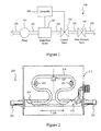
- Figure 2 provides a side elevational view, with partial cross section, of the internal structure of a representative Coriolis mass flow meter 200.
- Such meter 200 has a generally rectangular casing 212 within which are contained a pair of meter tubes or fluid flow conduits.
- An exemplary one of such meter tubes 214 is shown by the partial sectional view of Figure 2 .
- Such meter tube 214 has an inlet portion generally 216 and an outlet portion generally 218 respectively associated with inlet and outlet fluid conduit connections 220 and 222.
- manifolds or other elements are used to split fluid flow entering connection 220 into two separate pathways directed to the respective meter tubes. At the outlet end, flows from the respective conduits are combined for emerging together via connection 222.
- the general flow direction within device 200 is in the direction of arrow 224.
- Meter tubes may be generally an omega shape as illustrated in Figure 2 , or may assume other shapes.
- Meter tubes are selected and appropriately mounted in mass flow meter 200 so as to have substantially the same mass distribution, moments of inertia, and elastic modules about their respective bending axes.
- the respective meter tubes are mounted within the mass flow meter so as to be parallel with each other between there respective end portions when not in use.
- a driver signal is provided to driver generally 228 to cause the meter tubes to vibrate.
- the meter tubes oscillate with each other with identical phase.
- Coriolis accelerations cause the signals between sensors 230 and 232 to "shift" out of phase.
- the phase on the inlet side of the meter tubes lags the driver 228.
- the phase on the outlet side of the meter tubes leads the driver 228.
- the sensors 230 and 232 produce sinusoidal signals representative of the motion of the meter tubes.
- the phase difference between the sensor signals is proportional to the mass flow of the fluid through the meter tubes.
- the frequency of vibration of the meter tubes is inversely proportional to the density of the fluid flowing in the meter tubes 214
- the Coriolis mass flow meter 200 is capable of providing an output signal(s) indicative of the mass rate of the fluid flowing in the mass flow meter 200 as well as the density of the fluid flowing in the mass flow meter 200.
- Coriolis mass flow meters are able to measure liquids and gases accurately, without the need of re-calibration, as long as the percentage of the minority state of the fluid (e.g ., vapor in the measurement of liquids) is kept below about 3% -5% by volume.
- the presence of a vapor in the fluid flowing in the meter tubes causes a decrease in the amplitude of vibration of the meter tubes, which correspondingly causes a decrease in measurement accuracy.
- a control valve 130 is connected downstream of mass flow meter 120 to regulate the back pressure on the fluid flowing in the mass flow meter.
- Control valve 130 is regulated by controller 150 in response to the presence of a vapor in the fluid so as to increase or decrease the back pressure applied on the fluid.
- An increase in back pressure accelerates the condensation of the vapor in contact with the cooler liquid by reducing the volume of the vapor in the fluid stream, and, if the back pressure is maintained above the vapor pressure of the liquid, prevents formation (flashing) of vapor upstream of the valve.
- controller 150 can be any of a variety of analog or digital devices that can be used to implement the control methods according to embodiments of the present disclosure.
- controller 150 can include a processor configured to execute software or hardware instructions to regulate the back pressure provided by control valve 130.
- the controller 150 can be a part of the internal electronics of mass flow meter 120 or can be separate from mass flow meter 120.
- the controller 150 can use a proportional-integral-derivative routine that uses an output signal provided by the mass flow meter to regulate the back pressure provided by the control valve 130.
- controller 150 can similarly use a proportional, proportional-integral, or proportional-derivative control routine to regulate control valve 130.
- Back pressure valve 140 is used to provide the fluid with sufficient pressure such that the fluid flowing into the mass flow meter is initially in a liquid state.
- back pressure valve 140 can be used to hold the fluid line closed until the pressure of the fluid exceeds the vapor pressure of the fluid. Such approach will prevent the fluid from flashing into the vapor state prior to opening the back pressure valve 140 and flowing the fluid into the mass flow meter 120. Pressure alone will reduce, not eliminate, the volume of vapor.
- Various other devices can be used to apply pressure to the fluid before flowing the fluid into mass flow meter 120. For instance, in alternative configurations, a differential pressure switch and solenoid valve can replace the back pressure valve 140.
- backpressure valve 140 alone is not sufficient to control flashing in conditions where the vapor pressure varies significantly as in the case of consecutive measurements of fluids with different vapor pressures.
- a backpressure valve that is adjusted to suppress flashing, at optimal flow, for low vapor pressure fluids will not suppress flashing when use with high vapor pressure fluids. In such cases the mentioned Dynamic-Adaptive system is necessary.
- fluid is provided to mass flow meter 120.
- Fluid can be provided to mass flow meter 120 by connecting a fluid source, such as a storage tank or tank truck, to the flow measurement system 100 and by using pump 110 to provide the fluid with a suitable flow rate.
- the back pressure valve 140 can be initially closed until the pressure builds to a pre-set value that exceeds the vapor pressure of the fluid, causing most of the fluid to condense to a liquid state.
- the fluid can be provided to the mass flow meter 120 by opening the back pressure valve 140.
- the mass flow meter 120 measures at least one parameter of the fluid flowing in the mass flow meter.
- This parameter can be, for instance, the mass flow of the fluid flowing in the mass flow meter 120 or the density of the fluid flowing in the mass flow meter 120.
- the mass flow and density measurement can be used to calculate a variety of other parameters, including volume flowrate, average line temperature, average density, observed specific gravity, standard specific gravity (60o F), volume correction factor, mass total, gross volume total, net volume total, etc.
- the mass flow meter 120 generates at least one output signal indicative of the measured parameter of the fluid. For instance, if mass flow meter 120 is a Coriolis mass flow meter, the mass flow meter 120 can provide sinusoidal output signals representative of the motion of the meter tubes. The phase difference between the sensor signals is proportional to the mass flow of the fluid through the meter tubes. The frequency of vibration of the meter tubes is inversely proportional to the density of the fluid flowing in the meter tubes. The amplitude of vibration is inversely proportional to the percentage of concentration of the minority fluid (vapor in a liquid + vapor mixture).
- the presence of a vapor is detected in the fluid.
- the presence of a vapor can be detected from the output signal provided by the mass flow meter 120.
- the methodology 300 detects the presence of a vapor in the fluid flowing in the mass flow meter by monitoring the amplitude of vibration of the Coriolis meter tubes. A drop in the amplitude of vibration of the meter tubes and the corresponding drop in the amplitude of the output signal accompanies a drop in density of the fluid and therefore the presence of a vapor. If there is no reduction in the amplitude of vibration, there is no significant presence of vapor flowing in the fluid and the mass flow meter 120 will continue to perform parameter measurements of the fluid without any adjustments to control valve 130.
- the methodology 300 can determine that a significant presence of vapor is present in the fluid.
- the controller 150 sends a control signal to the control valve 130 directing the control valve 130 to provide increased back pressure to the fluid.
- the increased back pressure causes the vapor in contact with the cooler liquid to condense into a liquid state and prevents the fluid from flashing.
- controller 150 can use the drop in output signal amplitude as part of a proportional-integral-derivative control routine to generate a control signal for a continuously variable control valve 130.
- the position of the aperture of continuously variable control valve 130 is modulated to gradually open or close depending on the output signal amplitude of the mass flow meter 120. For instance, if a liquid + vapor mixture is detected in the fluid from a drop in output signal amplitude, the position of the aperture of control valve 130 can be gradually closed to provide an increased back pressure on the fluid. As the output signal amplitude returns to normal, the position of the aperture of the control valve 130 can be gradually opened.
- control valve 130 achieves an optimum flow setting providing for maximum flow allowable with enough back pressure to keep the fluid in a liquid state.
- control methodology should be configured to prevent the control valve 130 from operating in a completely closed position to allow for entrapped bubbles of vapor to flow out of the mass flow meter.
- the methodology 300 can reduce the presence of vapor in the fluid during mass flow and other measurements. This increases the accuracy of the mass flow and other measurements performed by mass flow meter 120 and can lead to more accurate and efficient inventory management of the fluid flowing in flow measurement system 100.
- the embodiments of the present technology can be implemented using a minimal amount of equipment (e.g ., mass flow meter, controller, and control valve) with minimal cost.
- embodiments of the present technology can perform other functions that complement and enhance the flow measurement of the fluid.
- the methodology 400 provides for improved average parameter value calculations, such as average density calculations and equivalent liquid volumetric calculations, for a fluid flowing in flow measurement system 100.
- fluid is provided into a mass flow meter.
- the mass flow meter performs a parameter measurement for the fluid.
- a mass flow meter can perform a mass flow and/or a density measurement for the fluid.
- the parameter measurement can be used in an average parameter calculation, such as an average net density calculation, that assigns a weight to a particular parameter measurement based on whether a vapor is determined to be present in the fluid flowing in the mass flow meter.
- the methodology 400 determines whether a vapor is present in the fluid flowing in the mass flow meter. In one embodiment, this determination can be made based at least in part on the amplitude of the output signal provided by the mass flow meter. As discussed above, the amplitude of the output signal(s) provided by a Coriolis mass flow meter is inversely proportional to the concentration of the minority fluid flowing in the mass flow meter. If a significant vapor is present in the fluid, the amplitude of the output signal provided by the mass flow meter decreases. Such a decrease in output signal amplitude can signify that less weight (emphasis) is applied in the averaging of the liquid's density under these conditions.
- the methodology 400 can determine whether a vapor is present in the fluid flowing in mass flow meter 120 by monitoring the driver signal provided to the flow tubes of a Coriolis mass flow meter.
- the driver signal causes the meter tubes of a Coriolis mass flow meter to vibrate.
- the driver signal will increase in intensity in order to try to maintain the operating amplitude for the meter tubes.
- a driver signal that has reached its limit on the amount of energy or gain that can be provided to the flow tubes of a Coriolis mass flow meter is considered to be saturated.
- the driver signal will no longer be able maintain the operating amplitude for the meter tubes, sending the driver signal into saturation. If the driver signal for a Coriolis mass flow meter becomes saturated, the methodology 400 can determine that there is enough vapor present in the fluid flowing in mass flow meter 120 to stop averaging and to retain the weighted average value up to this point.
- the methodology 400 assigns a weight value to the parameter measurement based at least in part on whether a vapor is present in the fluid flowing in the mass flow meter. A parameter measurement having a relatively large weight value will more significantly affect the average parameter calculation than a parameter measurement having a small weight value. As shown at block 440, if a vapor is determined to be present in the fluid flowing in the mass flow meter, the methodology 400 assigns a lower weight value to the parameter measurement. At block 450, if a vapor is determined not to be present in the fluid flowing in the mass flow meter, the methodology 400 assigns a higher weight value to the parameter measurement.
- the first weight value is less than the second weight value.
- the first weight value can be zero and the second weight value can be a value that is greater than zero.
- the methodology 400 provides for an average parameter measurement that is more heavily based on parameter measurements performed when a vapor is not detected in the fluid flowing in the mass flow meter.
- the average parameter calculation can be for a variety of parameters of the fluid flowing in the mass flow meter.
- the average parameter calculation is an average density calculation.
- the average density calculation can be used to provide an equivalent liquid volume calculation by dividing the total measured mass of the fluid by the average density calculated according to the methodology 400 discussed above. Such equivalent liquid volume calculation provides enhanced accuracy because it is based on an average density calculation that discounts density measurements performed when a vapor is detected in the fluid flowing in the mass flow meter.
Abstract
Description
- The present technology generally relates to fluid flow measurement systems and more particularly to reducing the presence of vapor and its detrimental effects in a fluid during flow measurements performed by a mass flow meter. The methods discussed hereon are not fluid dependent, but vapor-presence dependent, therefore, the methods apply to all liquefied compressed gases (LCG).
- Performing fluid flow measurements for LCG, such as liquid petroleum gas (LPG), entails a broader set of challenges that are not present in the measurement of other fluids. For the product to remain in a liquid state, LCG require the pressure of the fluid system to be maintained above the vapor pressure (i.e., the pressure at which a liquid-gas equilibrium occurs) for the fluid. If the pressure in the fluid system drops below the characteristic vapor pressure of the product, the liquid flashes (evaporates) to its vapor or gaseous state.
- The presence of a mixture of a vapor and a liquid in certain mass flow meters, such as Coriolis mass flow meters, can detrimentally affect the accuracy of the mass flow measurements and other measurements. For example, the mixture of gas and liquid in the fluid flowing in a Coriolis mass flow meter causes a decrease in the amplitude of vibration and a corresponding decrease in measurement accuracy. Error in density measurements is another detrimental effect of the presence of gas in fluid flow measurements. Because the average density of a liquid is greater than the average density of a gas, the presence of a mixture of gas and liquid in the fluid will yield an average density measurement that is too heavy for a gas and too light for a liquid. If such density measurement is used to convert measured mass to volume, the calculated volume could have a significant error when compared to calibrated volumetric references.
- Existing flow measurement systems rely on ancillary devices, such as vapor eliminator tanks, to provide vapor reduction. Vapor eliminator tanks can be used to trap some of the vapor originating before the eliminator tanks, but do not typically control vapor forming after the eliminator due to critical pressure drops. Another approach uses differential pressure valves to control line pressure, but the settings on the differential pressure valves are limited to a particular product with a particular vapor pressure. Therefore, such approach relies on the concept that the product's vapor pressure characteristics will remain unchanged. Other technologies use pressure transducers, control valves, and programmable logic controllers to control the line pressure. Such can be a technically effective alternative, but requires expensive equipment and extensive support.
-
U.S. Patent No. 6,471,487 to Keilty, et al. discloses a fluid delivery system that includes a Coriolis mass flow meter, a pump, a recirculation valve, and/or a back pressure valve. The fluid delivery system prevents the measurement of a multiphase fluid flow without the need for an air eliminator and strainer. If the measured density value exceeds one or more comparison values, the flow meter automatically shuts down the pump and closes the back pressure valve to stop the delivery of the fluid product from the fluid source to the destination to prevent the measurement of a multiphase fluid flow. However, this method requires extra piping for the recirculation path. - Other examples of U.S. Patents relating to Coriolis flow meter technology include
U.S. Patent No. 7,114,517 to Sund, et al. ,U.S. Patent No. 5,927,321 to Bergamini , andU.S. Patent No. 5,804,741 to Freeman . - The disclosures of the foregoing patents are fully incorporated herein for all purposes.
- There is a need for a fluid flow measurement system and methodology that reduces the presence of vapor using a minimal amount of equipment and minimal cost. While various methodologies have been developed for reducing detrimental effects caused by the presence of vapor in fluid flow measurement systems, no design has emerged that generally encompasses all of the desired characteristics, in an adaptive and dynamic form, as hereafter presented in accordance with the subject technology.
- In view of the recognized features encountered in the prior art and addressed by the present subject matter, improved system and methodology are presently disclosed for dynamic-adaptive vapor reduction in a fluid flow measurement system. It is to be understood that the present subject matter equally encompasses both system (apparatus) and methodology.
- In an exemplary configuration, a fluid flow measurement system and methodology that reduces the presence of a vapor in a fluid being measured in a mass flow meter is provided.
- In accordance with aspects of certain embodiments of the present disclosure, control flow valves are used to provide back pressure to prevent LCG from flashing while flowing in a mass flow meter.
- In accordance with yet further aspects of certain embodiments of the present disclosure, the flow measurement system and methodology identifies the density of a fluid in a liquid and gas flow mixture environment.
- In accordance with yet further aspects of certain embodiments of the present disclosure, the flow measurement system and methodology determines an equivalent liquid volumetric total from a dry vapor flow measurement.
- One exemplary embodiment of the present disclosure is directed to a fluid flow measurement system. The system includes a mass flow meter configured to measure at least one parameter of a fluid flowing in the mass flow meter and a control valve located downstream of the mass flow meter. The control valve provides a back pressure on the fluid flowing in the mass flow meter. The system further includes a controller configured to detect a vapor in the fluid flowing in the mass flow meter. The controller adjusts the control valve in response to detecting the vapor in the fluid so as to reduce the vapor in the fluid flowing in the mass flow meter.
- Variations and modifications can be made to such exemplary embodiment of the present disclosure. For instance, in one variation of this exemplary embodiment, the mass flow meter may provide an output signal indicative of at least one parameter measured by the mass flow meter and the controller may be further configured to detect a vapor in the fluid flowing in the mass flow meter based at least in part from the output signal.
- In another variation of such exemplary embodiment, the mass flow meter may be a Coriolis mass flow meter that includes both single and multiple tube transducers having an amplitude of vibration inversely proportional to the concentration of a minority state of the fluid (in a liquid + vapor mixture) flowing in the meter tubes. The Coriolis mass flow meter may provide an output signal having an output signal amplitude proportional to the amplitude of vibration of the meter tubes. The controller may be further configured to detect a vapor in the fluid flowing in the mass flow meter based on the output signal amplitude.
- In yet another variation of such exemplary embodiment, the controller may adjust the control valve to provide a back pressure sufficient to prevent the fluid flowing in the mass flow meter from flashing. In still another variation of such exemplary embodiment, the controller may adjust the control valve to provide a maximum flow rate with enough back pressure to prevent the fluid flowing in the mass flow meter from flashing.
- In still a further variation of such exemplary embodiment, the control valve may have a closed position and the controller may be further configured to prevent the control valve from operating in the closed position when fluid is flowing in the mass flow meter.
- Another exemplary embodiment of the present disclosure is directed to a method of reducing the amount of vapor in a fluid flowing in a mass flow meter. The method includes flowing a fluid into a mass flow meter; measuring at least one parameter of the fluid at the mass flow meter; detecting a vapor in the fluid flowing in the mass flow meter; and adjusting a control valve located downstream of the mass flow meter in response to detecting a vapor in the fluid flowing in the mass flow meter such that the amount of vapor in the fluid flowing in the mass flow meter is reduced.
- In a variation of such exemplary embodiment, the method may include providing an output signal from the mass flow meter indicative of the at least one parameter measured by the mass flow meter; and detecting a vapor in the fluid flowing in the mass flow meter from the output signal.
- In another variation of such exemplary embodiment, the mass flow meter can be a Coriolis mass flow meter having an amplitude of vibration inversely proportional to the percentage of minority fluid flowing in said meter tubes. The method can include providing an output signal having an output signal amplitude proportional to the amplitude of vibration of the meter tubes; and detecting a vapor in the fluid flowing in the mass flow meter based on the output signal amplitude.
- In still another variation of such exemplary embodiment, the step of adjusting a control valve may comprise adjusting the control valve to provide a back pressure sufficient to prevent the fluid flowing in the mass flow meter from flashing. In still a further variation of such exemplary embodiment, the step of adjusting a control valve may comprise adjusting the control valve to provide a maximum flow rate with enough back pressure to prevent the fluid flowing in the mass flow meter from flashing.
- In a further variation of such exemplary embodiment, the control valve may have a closed position and the method may further include preventing the control valve from operating in the closed position when fluid is flowing in the mass flow meter.
- In still a further variation of such exemplary embodiment, the method can include monitoring the pressure of the fluid and opening a back pressure valve located downstream of the mass flow meter to allow fluid to flow into the mass flow meter when the pressure of the fluid exceeds a vapor pressure for the fluid.
- A further exemplary embodiment of the present disclosure is directed to a method of determining an average parameter value of a fluid. The method includes flowing fluid in a mass flow meter; measuring at least one parameter value for the fluid flowing in the mass flow meter; determining whether a vapor is present in the fluid flowing in the mass flow meter; assigning a weight value to the at least one parameter value based at least in part on the presence of a vapor in the fluid flowing in the mass flow meter; and calculating a weighted average parameter value using the at least one parameter value and the weight value assigned to the at least one parameter value.
- In a variation of such exemplary embodiment, the step of assigning a weight value may include assigning a first weight value to the at least one parameter value if a vapor is determined to be present in the mass flow meter and assigning a second weight value to the at least one parameter value if a vapor is not determined to be present in the mass flow meter, preferably with the first weight value being less than the second weight value. For instance, in a particular embodiment, the first weight value can be approximately zero.
- In another variation of such exemplary embodiment, the mass flow meter may be a Coriolis mass flow meter and the method may further include monitoring a driver signal provided to the Coriolis mass flow meter; determining whether the driver signal is saturated; and determining that a vapor is present in the fluid flowing in the Coriolis mass flow meter when the driver signal is saturated.
- In another variation of such exemplary embodiment, the average parameter value may comprise the average density of the fluid flowing in the mass flow meter. In yet another variation of such exemplary embodiment, the method may include measuring the total mass of the fluid flowing in the mass flow meter and determining an equivalent liquid volume, in a mixture of liquid, liquid + vapor, and/or vapor, for the fluid flowing in the mass flow meter by dividing the total mass flowing in the mass flow meter by the average density.
- Additional objects and advantages of the present subject matter are set forth in, or will be apparent to, those of ordinary skill in the art from the detailed description herein. Also, it should be further appreciated that modifications and variations to the specifically illustrated, referred and discussed features, elements, and steps hereof may be practiced in various embodiments and uses of the present subject matter without departing from the spirit and scope of the present subject matter. Variations may include, but are not limited to, substitution of equivalent means, features, or steps for those illustrated, referenced, or discussed, and the functional, operational, or positional reversal of various parts, features, steps, or the like.
- Still further, it is to be understood that different embodiments, as well as different presently preferred embodiments, of the present subject matter may include various combinations or configurations of presently disclosed features, steps, or elements, or their equivalents (including combinations of features, parts, or steps or configurations thereof not expressly shown in the figures or stated in the detailed description of such figures). Additional embodiments of the present subject matter, not necessarily expressed in the summarized section, may include and incorporate various combinations of aspects of features, components, or steps referenced in the summarized objects above, and/or other features, components, or steps as otherwise discussed in this application. Those of ordinary skill in the art will better appreciate the features and aspects of such embodiments, and others, upon review of the remainder of the specification.
- A full and enabling disclosure of the present subject matter, including the best mode thereof, directed to one of ordinary skill in the art, is set forth in the specification, which makes reference to the appended figures in which:
- Figure 1
- is a fluid flow diagram (with intended flow illustrated left to right) of a fluid flow measurement system according to one exemplary embodiment of the present disclosure;
- Figure 2
- provides a side elevational view, in partial cutaway, of an exemplary Coriolis mass flow meter that can be used in accordance with exemplary embodiments of the present disclosure;
- Figure 3
- provides a flow diagram of an exemplary method according to one embodiment of the present disclosure; and
- Figure 4
- provides a flow diagram of an exemplary method according to one embodiment of the present disclosure;
- Repeat use of reference characters throughout the present specification and appended drawings is intended to represent same or analogous features, elements, or steps of the present subject matter.
- Reference now will be made in detail to embodiments of the present subject matter, one or more examples of which are illustrated in the drawings. Each example is provided by way of explanation of the present subject matter, not limitation of the present subject matter. In fact, it will be apparent to those skilled in the art that various modifications and variations can be made in the present subject matter without departing from the scope or spirit of the present subject matter. For instance, features illustrated or described as part of one embodiment, can be used with another embodiment to yield a still further embodiment. Thus, it is intended that the present subject matter encompass such modifications and variations as come within the scope of the appended claims and their equivalents.
- In general, the present technology provides for improved flow measurements for LCG, such as LPG. Embodiments of the present technology detect the presence of a vapor in a fluid flowing in a mass flow meter. A control valve is then adjusted to provide enough back pressure to prevent the measured liquid from flashing and to reduce the presence of vapor in the fluid flowing in the mass flow meter. By keeping the fluid in liquid form, the present technology reduces the vapor flowing in the mass flow meter, increasing the accuracy of mass flow and other measurements.
- Utilizing a similar principle of vapor detection, embodiments of the present technology provide for improved average parameter value calculation, such as average density measurements and equivalent liquid volumetric calculations in mixed (liquid + vapor) states. The average density measurements are performed pursuant to a weighted average algorithm that places weight on the individual mass flow measurements. A weighted average algorithm gives little to zero weight to density measurements performed when the system and methodology detects the presence of a vapor in the measured fluid, reducing the effect on averaging if there is a vapor in the measured fluid. In the measurement of LCG in its gaseous form, the average density calculation can be used to provide a more accurate Equivalent Liquid Volume calculation by dividing the total measured mass of the gas state fluid by the average density of the previously measured [pure] liquid state calculated according to the weighted average algorithm.
-
Figure 1 illustrates an exemplary flow measurement system generally 100 according to one exemplary embodiment of the present disclosure.Flow measurement system 100 can be used as part of a fluid delivery system for a volatile fluid, such as LPG.Flow measurement system 100 determines or measures a variety of parameters for a fluid flowing inflow measurement system 100, including for instance, mass flow rate, volume flow rate, average line temperature, average density, observed specific gravity, standard specific gravity (60º F), volume correction factor, mass total, gross volume total, net volume total, etc. The values for any of the above parameters can be used as part of an inventory management system for a fluid delivery system or for other suitable purposes. - As illustrated, flow
measurement system 100 can include apump 110, amass flow meter 120, acontrol valve 130, and aback pressure valve 140. The various components of theflow measurement system 100 can be coupled together usingpiping 105. Those of ordinary skill in the art, using the disclosures provided herein, should understand that various different types of piping can be used to connect the various components offlow measurement system 100 as a matter of design choice and that the present disclosure is not limited to any particular kind or configuration ofpiping 105. -
Flow measurement system 100 receives a fluid from a fluid source such as a storage tank or tank truck.Pump 110 is used to provide the fluid with a desired flow rate from the fluid source. Any pump, compressor, or other device can be used to provide the fluid with a desired flow rate into the mass flow meter. Preferably, thepump 110 is sized to provide the fluid with a flow rate that matches the flow rating of themass flow meter 120. - The fluid is provided through
pump 110 tomass flow meter 120.Mass flow meter 120 is used to measure one or more parameters of the fluid and provides one or more output signals indicative of the measured parameters. A typicalmass flow meter 120 will provide a mass flow measurement and a density measurement for the fluid flowing in the mass flow meter. In one exemplary embodiment,mass flow meter 120 can be a Coriolis mass flow meter. Details of an exemplary Coriolis mass flow meter generally 200 are represented inFigure 2 . The construction and operation of a Coriolis mass flow meter are known in the art and are exemplified inU.S. Patent No. 5,804,741 , which is incorporated herein by reference. - Briefly,
Figure 2 provides a side elevational view, with partial cross section, of the internal structure of a representative Coriolismass flow meter 200.Such meter 200 has a generallyrectangular casing 212 within which are contained a pair of meter tubes or fluid flow conduits. An exemplary one ofsuch meter tubes 214 is shown by the partial sectional view ofFigure 2 .Such meter tube 214 has an inlet portion generally 216 and an outlet portion generally 218 respectively associated with inlet and outletfluid conduit connections flow entering connection 220 into two separate pathways directed to the respective meter tubes. At the outlet end, flows from the respective conduits are combined for emerging together viaconnection 222. Hence, the general flow direction withindevice 200 is in the direction ofarrow 224. - Meter tubes may be generally an omega shape as illustrated in
Figure 2 , or may assume other shapes. Meter tubes are selected and appropriately mounted inmass flow meter 200 so as to have substantially the same mass distribution, moments of inertia, and elastic modules about their respective bending axes. The respective meter tubes are mounted within the mass flow meter so as to be parallel with each other between there respective end portions when not in use. In accordance with well known principles, a driver signal is provided to driver generally 228 to cause the meter tubes to vibrate. When there is no mass flow through the meter tubes, the meter tubes oscillate with each other with identical phase. As fluid begins to flow in the meter tubes, Coriolis accelerations cause the signals betweensensors 230 and 232 to "shift" out of phase. The phase on the inlet side of the meter tubes lags thedriver 228. The phase on the outlet side of the meter tubes leads thedriver 228. Thesensors 230 and 232 produce sinusoidal signals representative of the motion of the meter tubes. The phase difference between the sensor signals is proportional to the mass flow of the fluid through the meter tubes. The frequency of vibration of the meter tubes is inversely proportional to the density of the fluid flowing in themeter tubes 214 Thus, the Coriolismass flow meter 200 is capable of providing an output signal(s) indicative of the mass rate of the fluid flowing in themass flow meter 200 as well as the density of the fluid flowing in themass flow meter 200. - Coriolis mass flow meters are able to measure liquids and gases accurately, without the need of re-calibration, as long as the percentage of the minority state of the fluid (e.g., vapor in the measurement of liquids) is kept below about 3% -5% by volume. In a Coriolis mass flow meter, the presence of a vapor in the fluid flowing in the meter tubes causes a decrease in the amplitude of vibration of the meter tubes, which correspondingly causes a decrease in measurement accuracy.
- To reduce the detrimental effects caused by the presence of vapor flowing in
mass flow meter 120, acontrol valve 130 is connected downstream ofmass flow meter 120 to regulate the back pressure on the fluid flowing in the mass flow meter.Control valve 130 is regulated bycontroller 150 in response to the presence of a vapor in the fluid so as to increase or decrease the back pressure applied on the fluid. An increase in back pressure accelerates the condensation of the vapor in contact with the cooler liquid by reducing the volume of the vapor in the fluid stream, and, if the back pressure is maintained above the vapor pressure of the liquid, prevents formation (flashing) of vapor upstream of the valve. - Those of ordinary skill in the art, using the disclosures provided herein, should readily understand that the
controller 150 can be any of a variety of analog or digital devices that can be used to implement the control methods according to embodiments of the present disclosure. For instance,controller 150 can include a processor configured to execute software or hardware instructions to regulate the back pressure provided bycontrol valve 130. Thecontroller 150 can be a part of the internal electronics ofmass flow meter 120 or can be separate frommass flow meter 120. In a particular embodiment, thecontroller 150 can use a proportional-integral-derivative routine that uses an output signal provided by the mass flow meter to regulate the back pressure provided by thecontrol valve 130. However, other control routines can be utilized to regulatecontrol valve 130 without deviating from the spirit and scope of the present disclosure. For instance, as will be appreciated by those of ordinary skill in the art from the disclosures provided herein,controller 150 can similarly use a proportional, proportional-integral, or proportional-derivative control routine to regulatecontrol valve 130. - Back
pressure valve 140 is used to provide the fluid with sufficient pressure such that the fluid flowing into the mass flow meter is initially in a liquid state. In particular, aspump 110 begins providing pressure to the fluid, backpressure valve 140 can be used to hold the fluid line closed until the pressure of the fluid exceeds the vapor pressure of the fluid. Such approach will prevent the fluid from flashing into the vapor state prior to opening theback pressure valve 140 and flowing the fluid into themass flow meter 120. Pressure alone will reduce, not eliminate, the volume of vapor. Various other devices can be used to apply pressure to the fluid before flowing the fluid intomass flow meter 120. For instance, in alternative configurations, a differential pressure switch and solenoid valve can replace theback pressure valve 140. However,backpressure valve 140 alone is not sufficient to control flashing in conditions where the vapor pressure varies significantly as in the case of consecutive measurements of fluids with different vapor pressures. E.g.: A backpressure valve that is adjusted to suppress flashing, at optimal flow, for low vapor pressure fluids will not suppress flashing when use with high vapor pressure fluids. In such cases the mentioned Dynamic-Adaptive system is necessary. - With reference now to
Figure 3 , a present exemplary operation of fluidflow measurement system 100 will now be discussed in additional detail. Atblock 310, fluid is provided tomass flow meter 120. Fluid can be provided tomass flow meter 120 by connecting a fluid source, such as a storage tank or tank truck, to theflow measurement system 100 and by usingpump 110 to provide the fluid with a suitable flow rate. Theback pressure valve 140 can be initially closed until the pressure builds to a pre-set value that exceeds the vapor pressure of the fluid, causing most of the fluid to condense to a liquid state. The fluid can be provided to themass flow meter 120 by opening theback pressure valve 140. - At
block 320, themass flow meter 120 measures at least one parameter of the fluid flowing in the mass flow meter. This parameter can be, for instance, the mass flow of the fluid flowing in themass flow meter 120 or the density of the fluid flowing in themass flow meter 120. The mass flow and density measurement can be used to calculate a variety of other parameters, including volume flowrate, average line temperature, average density, observed specific gravity, standard specific gravity (60º F), volume correction factor, mass total, gross volume total, net volume total, etc. - At
block 330, themass flow meter 120 generates at least one output signal indicative of the measured parameter of the fluid. For instance, ifmass flow meter 120 is a Coriolis mass flow meter, themass flow meter 120 can provide sinusoidal output signals representative of the motion of the meter tubes. The phase difference between the sensor signals is proportional to the mass flow of the fluid through the meter tubes. The frequency of vibration of the meter tubes is inversely proportional to the density of the fluid flowing in the meter tubes. The amplitude of vibration is inversely proportional to the percentage of concentration of the minority fluid (vapor in a liquid + vapor mixture). - At
block 340, the presence of a vapor is detected in the fluid. The presence of a vapor can be detected from the output signal provided by themass flow meter 120. For instance, in a particular embodiment, themethodology 300 detects the presence of a vapor in the fluid flowing in the mass flow meter by monitoring the amplitude of vibration of the Coriolis meter tubes. A drop in the amplitude of vibration of the meter tubes and the corresponding drop in the amplitude of the output signal accompanies a drop in density of the fluid and therefore the presence of a vapor. If there is no reduction in the amplitude of vibration, there is no significant presence of vapor flowing in the fluid and themass flow meter 120 will continue to perform parameter measurements of the fluid without any adjustments to controlvalve 130. - If a reduction in vibration amplitude is detected, the
methodology 300 can determine that a significant presence of vapor is present in the fluid. Atblock 350, thecontroller 150 sends a control signal to thecontrol valve 130 directing thecontrol valve 130 to provide increased back pressure to the fluid. The increased back pressure causes the vapor in contact with the cooler liquid to condense into a liquid state and prevents the fluid from flashing. - In a particular embodiment,
controller 150 can use the drop in output signal amplitude as part of a proportional-integral-derivative control routine to generate a control signal for a continuouslyvariable control valve 130. The position of the aperture of continuouslyvariable control valve 130 is modulated to gradually open or close depending on the output signal amplitude of themass flow meter 120. For instance, if a liquid + vapor mixture is detected in the fluid from a drop in output signal amplitude, the position of the aperture ofcontrol valve 130 can be gradually closed to provide an increased back pressure on the fluid. As the output signal amplitude returns to normal, the position of the aperture of thecontrol valve 130 can be gradually opened. This process can continue until thecontrol valve 130 achieves an optimum flow setting providing for maximum flow allowable with enough back pressure to keep the fluid in a liquid state. Preferably, the control methodology should be configured to prevent thecontrol valve 130 from operating in a completely closed position to allow for entrapped bubbles of vapor to flow out of the mass flow meter. - By making adjustments to control
valve 130 in response to the presence of vapor in the fluid flowing inmass flow meter 120, themethodology 300 can reduce the presence of vapor in the fluid during mass flow and other measurements. This increases the accuracy of the mass flow and other measurements performed bymass flow meter 120 and can lead to more accurate and efficient inventory management of the fluid flowing inflow measurement system 100. Moreover, the embodiments of the present technology can be implemented using a minimal amount of equipment (e.g., mass flow meter, controller, and control valve) with minimal cost. In addition, as discussed below, embodiments of the present technology can perform other functions that complement and enhance the flow measurement of the fluid. - For example, with reference to
Figure 4 , another exemplary embodiment of the present disclosure for performing an average parameter calculation will be discussed in detail. Utilizing a similar principle of vapor detection, themethodology 400 provides for improved average parameter value calculations, such as average density calculations and equivalent liquid volumetric calculations, for a fluid flowing inflow measurement system 100. - At
block 410, fluid is provided into a mass flow meter. Atblock 420, the mass flow meter performs a parameter measurement for the fluid. For instance, a mass flow meter can perform a mass flow and/or a density measurement for the fluid. As will be discussed in additional detail below, the parameter measurement can be used in an average parameter calculation, such as an average net density calculation, that assigns a weight to a particular parameter measurement based on whether a vapor is determined to be present in the fluid flowing in the mass flow meter. - At
block 430, themethodology 400 determines whether a vapor is present in the fluid flowing in the mass flow meter. In one embodiment, this determination can be made based at least in part on the amplitude of the output signal provided by the mass flow meter. As discussed above, the amplitude of the output signal(s) provided by a Coriolis mass flow meter is inversely proportional to the concentration of the minority fluid flowing in the mass flow meter. If a significant vapor is present in the fluid, the amplitude of the output signal provided by the mass flow meter decreases. Such a decrease in output signal amplitude can signify that less weight (emphasis) is applied in the averaging of the liquid's density under these conditions. - In another embodiment, the
methodology 400 can determine whether a vapor is present in the fluid flowing inmass flow meter 120 by monitoring the driver signal provided to the flow tubes of a Coriolis mass flow meter. As discussed above, the driver signal causes the meter tubes of a Coriolis mass flow meter to vibrate. When the amplitude of vibration of the meter tubes decreases due to the presence of a vapor, the driver signal will increase in intensity in order to try to maintain the operating amplitude for the meter tubes. However, there is a limit on the amount of energy or gain that can be provided by the driver signal to the flow tubes of a Coriolis mass flow meter. A driver signal that has reached its limit on the amount of energy or gain that can be provided to the flow tubes of a Coriolis mass flow meter is considered to be saturated. When the amplitude of vibration decreases beyond a certain point, the driver signal will no longer be able maintain the operating amplitude for the meter tubes, sending the driver signal into saturation. If the driver signal for a Coriolis mass flow meter becomes saturated, themethodology 400 can determine that there is enough vapor present in the fluid flowing inmass flow meter 120 to stop averaging and to retain the weighted average value up to this point. - The
methodology 400 assigns a weight value to the parameter measurement based at least in part on whether a vapor is present in the fluid flowing in the mass flow meter. A parameter measurement having a relatively large weight value will more significantly affect the average parameter calculation than a parameter measurement having a small weight value. As shown atblock 440, if a vapor is determined to be present in the fluid flowing in the mass flow meter, themethodology 400 assigns a lower weight value to the parameter measurement. Atblock 450, if a vapor is determined not to be present in the fluid flowing in the mass flow meter, themethodology 400 assigns a higher weight value to the parameter measurement. - In accordance with embodiments of the present technology, the first weight value is less than the second weight value. For instance, in particular embodiments the first weight value can be zero and the second weight value can be a value that is greater than zero. In this manner, the
methodology 400 provides for an average parameter measurement that is more heavily based on parameter measurements performed when a vapor is not detected in the fluid flowing in the mass flow meter. - The average parameter calculation can be for a variety of parameters of the fluid flowing in the mass flow meter. For instance, in one embodiment, the average parameter calculation is an average density calculation. The average density calculation can be used to provide an equivalent liquid volume calculation by dividing the total measured mass of the fluid by the average density calculated according to the
methodology 400 discussed above. Such equivalent liquid volume calculation provides enhanced accuracy because it is based on an average density calculation that discounts density measurements performed when a vapor is detected in the fluid flowing in the mass flow meter. - While the present subject matter has been described in detail with respect to specific embodiments thereof, it will be appreciated that those skilled in the art, upon attaining an understanding of the foregoing may readily produce alterations to, variations of, and equivalents to such embodiments. Accordingly, the scope of the present disclosure is by way of example rather than by way of limitation, and the subject disclosure is not intended to preclude inclusion of such modifications, variations and/or additions to the present subject matter as would be readily apparent to one of ordinary skill in the art.
Claims (22)
- A flow measurement system, comprising:a mass flow meter configured to measure at least one parameter of a fluid flowing in said mass flow meter;a control valve located downstream of said mass flow meter, said control valve providing a back pressure on the fluid flowing in said mass flow meter; anda controller configured to detect a vapor in the fluid flowing in said mass flow meter;wherein the controller adjusts the control valve in response to detecting the vapor in the fluid so as to reduce the vapor in the fluid flowing in said mass flow meter.
- The system of claim 1, wherein said mass flow meter provides an output signal indicative of said at least one parameter measured by said mass flow meter, said controller configured to detect a vapor in the fluid flowing in said mass flow meter based at least in part from said output signal.
- The system of claim 1, wherein said mass flow meter is a Coriolis mass flow meter comprising at least one tube having an amplitude of vibration inversely proportional to the percentage of concentration of the minority fluid flowing in said meter tubes, said Coriolis mass flow meter providing an output signal having an output signal amplitude proportional to the amplitude of vibration of said meter tubes, said controller configured to detect a vapor in the fluid flowing in said mass flow meter based on said output signal amplitude.
- The system of claim 3, wherein said Coriolis mass flow meter comprises multiple tubes, and said minority fluid comprises one of vapor in liquid flow and liquid in vapor flow.
- The system of claim 1, wherein said controller adjusts said control valve to provide a back pressure sufficient to prevent the fluid flowing in said mass flow meter from flashing.
- The system of claim 1, wherein said controller adjusts the control valve to provide a maximum flow rate with enough back pressure to prevent the fluid flowing in said mass flow meter from flashing.
- The system of claim 1, wherein said control valve has a closed position, and said controller is further configured to prevent said control valve from operating in said closed position when fluid is flowing in said mass flow meter.
- The system of claim 1, wherein said system further comprises one of a back pressure valve and a differential pressure switch.
- A method of reducing the amount of vapor in a fluid flowing in a mass flow meter, the method comprising:flowing a fluid into a mass flow meter;measuring at least one parameter of the fluid at the mass flow meter;detecting a vapor in the fluid flowing in the mass flow meter; andadjusting a control valve located downstream of the mass flow meter in response to detecting a vapor in the fluid flowing in the mass flow meter such that the amount of vapor in the fluid flowing in the mass flow meter is reduced.
- The method of claim 9, wherein said method comprises:providing an output signal from the mass flow meter indicative of the at least one parameter measured by the mass flow meter; anddetecting a vapor in the fluid flowing in the mass flow meter from the output signal.
- The method of claim 9, wherein the mass flow meter is a Coriolis mass flow meter comprising at least one tube having an amplitude of vibration inversely proportional to the concentration of the minority fluid flowing in said meter tubes, and wherein the method further comprises:providing an output signal having an output signal amplitude proportional to the amplitude of vibration of the meter tubes; anddetecting a vapor in the fluid flowing in the mass flow meter based on the output signal amplitude.
- The method of claim 11, wherein said Coriolis mass flow meter comprises multiple tubes, and said minority fluid comprises one of vapor in liquid flow and liquid in vapor flow.
- The method of claim 9, wherein adjusting a control valve comprises adjusting the control valve to provide a back pressure sufficient to prevent the fluid flowing in the mass flow meter from flashing.
- The method of claim 9, wherein adjusting a control valve comprises adjusting the control valve to provide a maximum flow rate with enough back pressure to prevent the fluid flowing in the mass flow meter from flashing.
- The method of claim 9, wherein the control valve has a closed position, and wherein the method further comprises preventing the control valve from operating in the closed position thereof when fluid is flowing in the mass flow meter.
- The method of claim 9, wherein the method further comprises:monitoring the presence of vapor in the fluid; andopening a back pressure valve located downstream of the mass flow meter to allow fluid to flow into the mass flow meter when the pressure of the fluid exceeds a vapor pressure for the fluid.
- A method of determining an average parameter value of a fluid, the method comprising:flowing fluid in a mass flow meter;measuring at least one parameter value for the fluid flowing in the mass flow meter;determining whether a vapor is present in the fluid flowing in the mass flow meter;assigning a weight value to the at least one parameter value based at least in part on the presence of a vapor in the fluid flowing in the mass flow meter; andcalculating an average parameter value using the at least one parameter value and the weight value assigned the at least one parameter value.
- The method of claim 17, wherein the step of assigning a weight value comprises:assigning a first weight value to the at least one parameter value if a vapor is determined to be present in the mass flow meter; andassigning a second weight value to the at least one parameter value when a vapor is not determined to be present in the mass flow meter, wherein the first weight value is less than the second weight value.
- The method of claim 17, wherein the first weight value is approximately zero.
- The method of claim 17, wherein:the mass flow meter is a Coriolis mass flow meter; andthe step of determining whether a vapor is present in the mass flow meter comprises:monitoring a driver signal provided to the Coriolis mass flow meter,determining whether the driver signal is saturated to determine that no further averaging should take place, anddetermining that a vapor is present in the fluid flowing in the Coriolis mass flow meter when the driver signal is saturated.
- The method of claim 17, wherein the average parameter value comprises the average density of the fluid flowing in the mass flow meter.
- The method of claim 21 wherein the method further comprises;measuring the total mass of the fluid flowing in the mass flow meter, anddetermining an equivalent liquid volume value from the average density of the fluid flowing in the mass flow meter by dividing the average density by the total mass flowing in the mass flow meter.
Applications Claiming Priority (1)
| Application Number | Priority Date | Filing Date | Title |
|---|---|---|---|
| US12/721,731 US9389111B2 (en) | 2010-03-11 | 2010-03-11 | Dynamic-adaptive vapor reduction system and method |
Publications (3)
| Publication Number | Publication Date |
|---|---|
| EP2365298A2 true EP2365298A2 (en) | 2011-09-14 |
| EP2365298A3 EP2365298A3 (en) | 2014-05-21 |
| EP2365298B1 EP2365298B1 (en) | 2020-05-27 |
Family
ID=44201928
Family Applications (1)
| Application Number | Title | Priority Date | Filing Date |
|---|---|---|---|
| EP11157397.8A Active EP2365298B1 (en) | 2010-03-11 | 2011-03-09 | Dynamic-adaptive vapor reduction system in a mass flowmeter and corresponding method |
Country Status (4)
| Country | Link |
|---|---|
| US (2) | US9389111B2 (en) |
| EP (1) | EP2365298B1 (en) |
| CA (1) | CA2732496A1 (en) |
| MX (1) | MX2011002557A (en) |
Cited By (1)
| Publication number | Priority date | Publication date | Assignee | Title |
|---|---|---|---|---|
| WO2017045887A1 (en) * | 2015-09-15 | 2017-03-23 | Endress+Hauser Flowtec Ag | Method and measurement device for determining the compressibility of a flowing fluid |
Families Citing this family (10)
| Publication number | Priority date | Publication date | Assignee | Title |
|---|---|---|---|---|
| CN102937240A (en) * | 2012-10-26 | 2013-02-20 | 西安东风机电有限公司 | Back pressure control method and application system for liquefied gas loading |
| WO2014152755A2 (en) * | 2013-03-14 | 2014-09-25 | Christopher Max Horwitz | Pressure-based gas flow controller with dynamic self-calibration |
| US9904296B2 (en) * | 2014-04-01 | 2018-02-27 | Honeywell International Inc. | Controlling flow in a fluid distribution system |
| US9435675B2 (en) * | 2014-10-02 | 2016-09-06 | BreatheWise, LLC | Method and apparatus for monitoring, communicating, and analyzing the amount of fluid in a tank |
| CN111316073B (en) * | 2017-11-13 | 2022-10-21 | 高准公司 | Flowing vapor pressure device and related method |
| GB201903473D0 (en) * | 2019-03-14 | 2019-05-01 | Sumitomo Chemical Co | Interferent and baseline drift correcting gas sensor system |
| BR112021018484B1 (en) * | 2019-04-03 | 2023-04-04 | Micro Motion, Inc | METER ELECTRONIC AND METHOD FOR USING A DENSITY MEASUREMENT OF A FLUID TO VERIFY A VAPOR PRESSURE |
| KR20210147015A (en) * | 2019-04-03 | 2021-12-06 | 마이크로 모우션, 인코포레이티드 | Determination of Steam Pressure Using Steam Manometer Coefficients |
| JP7345053B2 (en) * | 2019-08-19 | 2023-09-14 | マイクロ モーション インコーポレイテッド | True vapor pressure and flashing detection device and related methods |
| US11248943B2 (en) | 2019-08-29 | 2022-02-15 | Nautical Control Solutions, Lp | Mobile fuel measurement system |
Citations (4)
| Publication number | Priority date | Publication date | Assignee | Title |
|---|---|---|---|---|
| US5804741A (en) | 1996-11-08 | 1998-09-08 | Schlumberger Industries, Inc. | Digital phase locked loop signal processing for coriolis mass flow meter |
| US5927321A (en) | 1995-10-30 | 1999-07-27 | Nuovo Pignone, S.P.A. | System for measuring and controlling gas mass flow |
| US6471487B2 (en) | 2001-01-31 | 2002-10-29 | Micro Motion, Inc. | Fluid delivery system |
| US7114517B2 (en) | 2001-11-26 | 2006-10-03 | Sund Wesley E | High purity fluid delivery system |
Family Cites Families (17)
| Publication number | Priority date | Publication date | Assignee | Title |
|---|---|---|---|---|
| US2919834A (en) * | 1956-06-12 | 1960-01-05 | Rockwell Mfg Co | Dispensing system for highly volatile liquids |
| US4718443A (en) * | 1987-02-06 | 1988-01-12 | Conoco Inc. | Mass flowmeter apparatus |
| US5062446A (en) * | 1991-01-07 | 1991-11-05 | Sematech, Inc. | Intelligent mass flow controller |
| US5944048A (en) * | 1996-10-04 | 1999-08-31 | Emerson Electric Co. | Method and apparatus for detecting and controlling mass flow |
| US7344297B2 (en) * | 1998-04-16 | 2008-03-18 | Air Liquide Electronics U.S. Lp | Method and apparatus for asynchronous blending and supply of chemical solutions |
| US6067917A (en) * | 1998-05-29 | 2000-05-30 | Pgi International, Ltd. | Method and apparatus for flow control of NH3 |
| US6327914B1 (en) * | 1998-09-30 | 2001-12-11 | Micro Motion, Inc. | Correction of coriolis flowmeter measurements due to multiphase flows |
| US6318156B1 (en) * | 1999-10-28 | 2001-11-20 | Micro Motion, Inc. | Multiphase flow measurement system |
| US7592033B2 (en) * | 2003-07-08 | 2009-09-22 | Computrol, Inc | Variable fluid dispenser |
| BRPI0418910B1 (en) * | 2004-06-22 | 2016-11-16 | Micro Motion Inc | Meter Electronics and Method for Detecting Residual Material in a Flow Meter Assembly |
| AR054460A1 (en) * | 2005-05-27 | 2007-06-27 | Micro Motion Inc | ELECTRONIC MEASUREMENT EQUIPMENT AND METHODS TO DETECT A FLOW ANOMALY IN A FLOW MATERIAL |
| WO2007008793A2 (en) * | 2005-07-11 | 2007-01-18 | Phase Dynamics | Multiphase fluid characterization |
| US7971604B2 (en) * | 2006-04-20 | 2011-07-05 | Hitachi Metals, Ltd. | Flow controller delivery of a specified-quantity of a fluid |
| US20090107218A1 (en) * | 2007-10-30 | 2009-04-30 | Chesapeake Operating, Inc. | Test separator |
| US7693606B2 (en) * | 2007-12-21 | 2010-04-06 | Rosemount Inc. | Diagnostics for mass flow control |
| JP2010169657A (en) * | 2008-12-25 | 2010-08-05 | Horiba Stec Co Ltd | Mass flow meter and mass flow controller |
| BR112016007604A2 (en) | 2013-11-14 | 2017-08-01 | Halliburton Energy Services Inc | method for variation and variation system |
-
2010
- 2010-03-11 US US12/721,731 patent/US9389111B2/en active Active
-
2011
- 2011-02-23 CA CA 2732496 patent/CA2732496A1/en not_active Abandoned
- 2011-03-09 MX MX2011002557A patent/MX2011002557A/en active IP Right Grant
- 2011-03-09 EP EP11157397.8A patent/EP2365298B1/en active Active
-
2016
- 2016-06-22 US US15/189,063 patent/US9970596B2/en active Active
Patent Citations (4)
| Publication number | Priority date | Publication date | Assignee | Title |
|---|---|---|---|---|
| US5927321A (en) | 1995-10-30 | 1999-07-27 | Nuovo Pignone, S.P.A. | System for measuring and controlling gas mass flow |
| US5804741A (en) | 1996-11-08 | 1998-09-08 | Schlumberger Industries, Inc. | Digital phase locked loop signal processing for coriolis mass flow meter |
| US6471487B2 (en) | 2001-01-31 | 2002-10-29 | Micro Motion, Inc. | Fluid delivery system |
| US7114517B2 (en) | 2001-11-26 | 2006-10-03 | Sund Wesley E | High purity fluid delivery system |
Cited By (2)
| Publication number | Priority date | Publication date | Assignee | Title |
|---|---|---|---|---|
| WO2017045887A1 (en) * | 2015-09-15 | 2017-03-23 | Endress+Hauser Flowtec Ag | Method and measurement device for determining the compressibility of a flowing fluid |
| US10830681B2 (en) | 2015-09-15 | 2020-11-10 | Endress+Hauser Flowtec Ag | Method and measuring apparatus for determining compressibility of a flowing fluid |
Also Published As
| Publication number | Publication date |
|---|---|
| EP2365298B1 (en) | 2020-05-27 |
| US9970596B2 (en) | 2018-05-15 |
| MX2011002557A (en) | 2011-09-21 |
| EP2365298A3 (en) | 2014-05-21 |
| CA2732496A1 (en) | 2011-09-11 |
| US9389111B2 (en) | 2016-07-12 |
| US20160305614A1 (en) | 2016-10-20 |
| US20110220213A1 (en) | 2011-09-15 |
Similar Documents
| Publication | Publication Date | Title |
|---|---|---|
| US9970596B2 (en) | Dynamic-adaptive vapor reduction system and method | |
| CA2433945C (en) | Fluid delivery system | |
| AU2007354291B2 (en) | Vibratory flow meter and method for correcting for entrained gas in a flow material | |
| US10139259B2 (en) | System and method for metering gas based on amplitude and/or temporal characteristics of an electrical signal | |
| CN108700445B (en) | Measuring device for monitoring oil addition of large ship | |
| CN103562688A (en) | Flowmeter for two-phase gas/liquid cryogenic fluids | |
| US20070163361A1 (en) | Reduced bore vortex flowmeter having a stepped intake | |
| AU2014351681A1 (en) | Flowmeter for two-phase fluid with simultaneous or alternating measurement of the gas phase and the liquid phase | |
| JP4616979B2 (en) | A device that continuously measures the dynamic fuel consumption of a consumer | |
| CN110726444A (en) | Wet gas flow metering method and device based on Coriolis mass flowmeter | |
| JP2024023472A (en) | Validating Vapor Pressure Using Fluid Density Measurements | |
| JP2008089373A (en) | Flow measurement by coriolis flowmeter, and flow controller | |
| US20220034697A1 (en) | Wet gas flow rate metering method based on a coriolis mass flowmeter and device thereof | |
| JP2022028913A (en) | Flowing vapor pressure apparatus and related method | |
| EP3312573B1 (en) | System and method for fluid metering | |
| BRPI1100949A2 (en) | Dynamic Adaptive Steam Reduction System and Method | |
| RU2793602C1 (en) | True vapor pressure and fast vapor detection device and related method | |
| RU2785829C1 (en) | Determining vapour pressure using the coefficient of a vapour pressure meter | |
| RU2787932C1 (en) | Determining the pressure of vapour of a fluid in a measuring assembly | |
| KR20180047205A (en) | A Mass Flow Meter For Ship Useing Coriolis Force | |
| KR20210146393A (en) | Determination of the vapor pressure of a fluid within a metering assembly | |
| KR20240010110A (en) | Determining a vapor pressure using a vapor pressure meter factor |
Legal Events
| Date | Code | Title | Description |
|---|---|---|---|
| PUAI | Public reference made under article 153(3) epc to a published international application that has entered the european phase |
Free format text: ORIGINAL CODE: 0009012 |
|
| AK | Designated contracting states |
Kind code of ref document: A2 Designated state(s): AL AT BE BG CH CY CZ DE DK EE ES FI FR GB GR HR HU IE IS IT LI LT LU LV MC MK MT NL NO PL PT RO RS SE SI SK SM TR |
|
| AX | Request for extension of the european patent |
Extension state: BA ME |
|
| RIC1 | Information provided on ipc code assigned before grant |
Ipc: G01F 1/84 20060101ALI20140204BHEP Ipc: G01N 9/00 20060101ALI20140204BHEP Ipc: G01F 15/00 20060101AFI20140204BHEP |
|
| PUAL | Search report despatched |
Free format text: ORIGINAL CODE: 0009013 |
|
| 17P | Request for examination filed |
Effective date: 20140331 |
|
| RBV | Designated contracting states (corrected) |
Designated state(s): AL AT BE BG CH CY CZ DE DK EE ES FI FR GB GR HR HU IE IS IT LI LT LU LV MC MK MT NL NO PL PT RO RS SE SI SK SM TR |
|
| AK | Designated contracting states |
Kind code of ref document: A3 Designated state(s): AL AT BE BG CH CY CZ DE DK EE ES FI FR GB GR HR HU IE IS IT LI LT LU LV MC MK MT NL NO PL PT RO RS SE SI SK SM TR |
|
| AX | Request for extension of the european patent |
Extension state: BA ME |
|
| RIC1 | Information provided on ipc code assigned before grant |
Ipc: G01F 15/00 20060101AFI20140417BHEP Ipc: G01N 9/00 20060101ALI20140417BHEP Ipc: G01F 1/84 20060101ALI20140417BHEP |
|
| RAP1 | Party data changed (applicant data changed or rights of an application transferred) |
Owner name: MEASUREMENT TECHNOLOGY GROUP, INC. |
|
| STAA | Information on the status of an ep patent application or granted ep patent |
Free format text: STATUS: EXAMINATION IS IN PROGRESS |
|
| 17Q | First examination report despatched |
Effective date: 20180627 |
|
| REG | Reference to a national code |
Ref country code: DE Ref legal event code: R079 Ref document number: 602011067002 Country of ref document: DE Free format text: PREVIOUS MAIN CLASS: G01F0015000000 Ipc: G01N0009320000 |
|
| GRAP | Despatch of communication of intention to grant a patent |
Free format text: ORIGINAL CODE: EPIDOSNIGR1 |
|
| STAA | Information on the status of an ep patent application or granted ep patent |
Free format text: STATUS: GRANT OF PATENT IS INTENDED |
|
| RIC1 | Information provided on ipc code assigned before grant |
Ipc: G01F 15/00 20060101ALI20191105BHEP Ipc: G01F 15/02 20060101ALI20191105BHEP Ipc: G01N 9/00 20060101ALI20191105BHEP Ipc: G01N 9/32 20060101AFI20191105BHEP Ipc: G01F 1/84 20060101ALI20191105BHEP |
|
| INTG | Intention to grant announced |
Effective date: 20191202 |
|
| GRAS | Grant fee paid |
Free format text: ORIGINAL CODE: EPIDOSNIGR3 |
|
| GRAA | (expected) grant |
Free format text: ORIGINAL CODE: 0009210 |
|
| STAA | Information on the status of an ep patent application or granted ep patent |
Free format text: STATUS: THE PATENT HAS BEEN GRANTED |
|
| AK | Designated contracting states |
Kind code of ref document: B1 Designated state(s): AL AT BE BG CH CY CZ DE DK EE ES FI FR GB GR HR HU IE IS IT LI LT LU LV MC MK MT NL NO PL PT RO RS SE SI SK SM TR |
|
| REG | Reference to a national code |
Ref country code: GB Ref legal event code: FG4D |
|
| REG | Reference to a national code |
Ref country code: CH Ref legal event code: EP |
|
| REG | Reference to a national code |
Ref country code: AT Ref legal event code: REF Ref document number: 1275042 Country of ref document: AT Kind code of ref document: T Effective date: 20200615 |
|
| REG | Reference to a national code |
Ref country code: DE Ref legal event code: R096 Ref document number: 602011067002 Country of ref document: DE |
|
| REG | Reference to a national code |
Ref country code: LT Ref legal event code: MG4D |
|
| PG25 | Lapsed in a contracting state [announced via postgrant information from national office to epo] |
Ref country code: NO Free format text: LAPSE BECAUSE OF FAILURE TO SUBMIT A TRANSLATION OF THE DESCRIPTION OR TO PAY THE FEE WITHIN THE PRESCRIBED TIME-LIMIT Effective date: 20200827 Ref country code: IS Free format text: LAPSE BECAUSE OF FAILURE TO SUBMIT A TRANSLATION OF THE DESCRIPTION OR TO PAY THE FEE WITHIN THE PRESCRIBED TIME-LIMIT Effective date: 20200927 Ref country code: FI Free format text: LAPSE BECAUSE OF FAILURE TO SUBMIT A TRANSLATION OF THE DESCRIPTION OR TO PAY THE FEE WITHIN THE PRESCRIBED TIME-LIMIT Effective date: 20200527 Ref country code: PT Free format text: LAPSE BECAUSE OF FAILURE TO SUBMIT A TRANSLATION OF THE DESCRIPTION OR TO PAY THE FEE WITHIN THE PRESCRIBED TIME-LIMIT Effective date: 20200928 Ref country code: SE Free format text: LAPSE BECAUSE OF FAILURE TO SUBMIT A TRANSLATION OF THE DESCRIPTION OR TO PAY THE FEE WITHIN THE PRESCRIBED TIME-LIMIT Effective date: 20200527 Ref country code: LT Free format text: LAPSE BECAUSE OF FAILURE TO SUBMIT A TRANSLATION OF THE DESCRIPTION OR TO PAY THE FEE WITHIN THE PRESCRIBED TIME-LIMIT Effective date: 20200527 Ref country code: GR Free format text: LAPSE BECAUSE OF FAILURE TO SUBMIT A TRANSLATION OF THE DESCRIPTION OR TO PAY THE FEE WITHIN THE PRESCRIBED TIME-LIMIT Effective date: 20200828 |
|
| REG | Reference to a national code |
Ref country code: NL Ref legal event code: MP Effective date: 20200527 |
|
| PG25 | Lapsed in a contracting state [announced via postgrant information from national office to epo] |
Ref country code: BG Free format text: LAPSE BECAUSE OF FAILURE TO SUBMIT A TRANSLATION OF THE DESCRIPTION OR TO PAY THE FEE WITHIN THE PRESCRIBED TIME-LIMIT Effective date: 20200827 Ref country code: RS Free format text: LAPSE BECAUSE OF FAILURE TO SUBMIT A TRANSLATION OF THE DESCRIPTION OR TO PAY THE FEE WITHIN THE PRESCRIBED TIME-LIMIT Effective date: 20200527 Ref country code: LV Free format text: LAPSE BECAUSE OF FAILURE TO SUBMIT A TRANSLATION OF THE DESCRIPTION OR TO PAY THE FEE WITHIN THE PRESCRIBED TIME-LIMIT Effective date: 20200527 Ref country code: HR Free format text: LAPSE BECAUSE OF FAILURE TO SUBMIT A TRANSLATION OF THE DESCRIPTION OR TO PAY THE FEE WITHIN THE PRESCRIBED TIME-LIMIT Effective date: 20200527 |
|
| REG | Reference to a national code |
Ref country code: AT Ref legal event code: MK05 Ref document number: 1275042 Country of ref document: AT Kind code of ref document: T Effective date: 20200527 |
|
| PG25 | Lapsed in a contracting state [announced via postgrant information from national office to epo] |
Ref country code: AL Free format text: LAPSE BECAUSE OF FAILURE TO SUBMIT A TRANSLATION OF THE DESCRIPTION OR TO PAY THE FEE WITHIN THE PRESCRIBED TIME-LIMIT Effective date: 20200527 Ref country code: NL Free format text: LAPSE BECAUSE OF FAILURE TO SUBMIT A TRANSLATION OF THE DESCRIPTION OR TO PAY THE FEE WITHIN THE PRESCRIBED TIME-LIMIT Effective date: 20200527 |
|
| PG25 | Lapsed in a contracting state [announced via postgrant information from national office to epo] |
Ref country code: DK Free format text: LAPSE BECAUSE OF FAILURE TO SUBMIT A TRANSLATION OF THE DESCRIPTION OR TO PAY THE FEE WITHIN THE PRESCRIBED TIME-LIMIT Effective date: 20200527 Ref country code: ES Free format text: LAPSE BECAUSE OF FAILURE TO SUBMIT A TRANSLATION OF THE DESCRIPTION OR TO PAY THE FEE WITHIN THE PRESCRIBED TIME-LIMIT Effective date: 20200527 Ref country code: EE Free format text: LAPSE BECAUSE OF FAILURE TO SUBMIT A TRANSLATION OF THE DESCRIPTION OR TO PAY THE FEE WITHIN THE PRESCRIBED TIME-LIMIT Effective date: 20200527 Ref country code: CZ Free format text: LAPSE BECAUSE OF FAILURE TO SUBMIT A TRANSLATION OF THE DESCRIPTION OR TO PAY THE FEE WITHIN THE PRESCRIBED TIME-LIMIT Effective date: 20200527 Ref country code: SM Free format text: LAPSE BECAUSE OF FAILURE TO SUBMIT A TRANSLATION OF THE DESCRIPTION OR TO PAY THE FEE WITHIN THE PRESCRIBED TIME-LIMIT Effective date: 20200527 Ref country code: AT Free format text: LAPSE BECAUSE OF FAILURE TO SUBMIT A TRANSLATION OF THE DESCRIPTION OR TO PAY THE FEE WITHIN THE PRESCRIBED TIME-LIMIT Effective date: 20200527 Ref country code: RO Free format text: LAPSE BECAUSE OF FAILURE TO SUBMIT A TRANSLATION OF THE DESCRIPTION OR TO PAY THE FEE WITHIN THE PRESCRIBED TIME-LIMIT Effective date: 20200527 Ref country code: IT Free format text: LAPSE BECAUSE OF FAILURE TO SUBMIT A TRANSLATION OF THE DESCRIPTION OR TO PAY THE FEE WITHIN THE PRESCRIBED TIME-LIMIT Effective date: 20200527 |
|
| PG25 | Lapsed in a contracting state [announced via postgrant information from national office to epo] |
Ref country code: SK Free format text: LAPSE BECAUSE OF FAILURE TO SUBMIT A TRANSLATION OF THE DESCRIPTION OR TO PAY THE FEE WITHIN THE PRESCRIBED TIME-LIMIT Effective date: 20200527 Ref country code: PL Free format text: LAPSE BECAUSE OF FAILURE TO SUBMIT A TRANSLATION OF THE DESCRIPTION OR TO PAY THE FEE WITHIN THE PRESCRIBED TIME-LIMIT Effective date: 20200527 |
|
| REG | Reference to a national code |
Ref country code: DE Ref legal event code: R097 Ref document number: 602011067002 Country of ref document: DE |
|
| PLBE | No opposition filed within time limit |
Free format text: ORIGINAL CODE: 0009261 |
|
| STAA | Information on the status of an ep patent application or granted ep patent |
Free format text: STATUS: NO OPPOSITION FILED WITHIN TIME LIMIT |
|
| 26N | No opposition filed |
Effective date: 20210302 |
|
| PG25 | Lapsed in a contracting state [announced via postgrant information from national office to epo] |
Ref country code: SI Free format text: LAPSE BECAUSE OF FAILURE TO SUBMIT A TRANSLATION OF THE DESCRIPTION OR TO PAY THE FEE WITHIN THE PRESCRIBED TIME-LIMIT Effective date: 20200527 |
|
| REG | Reference to a national code |
Ref country code: DE Ref legal event code: R119 Ref document number: 602011067002 Country of ref document: DE |
|
| PG25 | Lapsed in a contracting state [announced via postgrant information from national office to epo] |
Ref country code: MC Free format text: LAPSE BECAUSE OF FAILURE TO SUBMIT A TRANSLATION OF THE DESCRIPTION OR TO PAY THE FEE WITHIN THE PRESCRIBED TIME-LIMIT Effective date: 20200527 |
|
| REG | Reference to a national code |
Ref country code: CH Ref legal event code: PL |
|
| GBPC | Gb: european patent ceased through non-payment of renewal fee |
Effective date: 20210309 |
|
| REG | Reference to a national code |
Ref country code: BE Ref legal event code: MM Effective date: 20210331 |
|
| PG25 | Lapsed in a contracting state [announced via postgrant information from national office to epo] |
Ref country code: CH Free format text: LAPSE BECAUSE OF NON-PAYMENT OF DUE FEES Effective date: 20210331 Ref country code: LU Free format text: LAPSE BECAUSE OF NON-PAYMENT OF DUE FEES Effective date: 20210309 Ref country code: LI Free format text: LAPSE BECAUSE OF NON-PAYMENT OF DUE FEES Effective date: 20210331 Ref country code: IE Free format text: LAPSE BECAUSE OF NON-PAYMENT OF DUE FEES Effective date: 20210309 Ref country code: GB Free format text: LAPSE BECAUSE OF NON-PAYMENT OF DUE FEES Effective date: 20210309 Ref country code: FR Free format text: LAPSE BECAUSE OF NON-PAYMENT OF DUE FEES Effective date: 20210331 Ref country code: DE Free format text: LAPSE BECAUSE OF NON-PAYMENT OF DUE FEES Effective date: 20211001 |
|
| PG25 | Lapsed in a contracting state [announced via postgrant information from national office to epo] |
Ref country code: BE Free format text: LAPSE BECAUSE OF NON-PAYMENT OF DUE FEES Effective date: 20210331 |
|
| PG25 | Lapsed in a contracting state [announced via postgrant information from national office to epo] |
Ref country code: HU Free format text: LAPSE BECAUSE OF FAILURE TO SUBMIT A TRANSLATION OF THE DESCRIPTION OR TO PAY THE FEE WITHIN THE PRESCRIBED TIME-LIMIT; INVALID AB INITIO Effective date: 20110309 Ref country code: CY Free format text: LAPSE BECAUSE OF FAILURE TO SUBMIT A TRANSLATION OF THE DESCRIPTION OR TO PAY THE FEE WITHIN THE PRESCRIBED TIME-LIMIT Effective date: 20200527 |