EP2365232A1 - Control method of the position of a solenoid valve using dithering - Google Patents
Control method of the position of a solenoid valve using dithering Download PDFInfo
- Publication number
- EP2365232A1 EP2365232A1 EP11157558A EP11157558A EP2365232A1 EP 2365232 A1 EP2365232 A1 EP 2365232A1 EP 11157558 A EP11157558 A EP 11157558A EP 11157558 A EP11157558 A EP 11157558A EP 2365232 A1 EP2365232 A1 EP 2365232A1
- Authority
- EP
- European Patent Office
- Prior art keywords
- dithering
- dith
- solenoid valve
- square wave
- obj
- Prior art date
- Legal status (The legal status is an assumption and is not a legal conclusion. Google has not performed a legal analysis and makes no representation as to the accuracy of the status listed.)
- Granted
Links
Images


Classifications
-
- G—PHYSICS
- G06—COMPUTING; CALCULATING OR COUNTING
- G06F—ELECTRIC DIGITAL DATA PROCESSING
- G06F17/00—Digital computing or data processing equipment or methods, specially adapted for specific functions
- G06F17/10—Complex mathematical operations
-
- F—MECHANICAL ENGINEERING; LIGHTING; HEATING; WEAPONS; BLASTING
- F16—ENGINEERING ELEMENTS AND UNITS; GENERAL MEASURES FOR PRODUCING AND MAINTAINING EFFECTIVE FUNCTIONING OF MACHINES OR INSTALLATIONS; THERMAL INSULATION IN GENERAL
- F16H—GEARING
- F16H61/00—Control functions within control units of change-speed- or reversing-gearings for conveying rotary motion ; Control of exclusively fluid gearing, friction gearing, gearings with endless flexible members or other particular types of gearing
- F16H61/02—Control functions within control units of change-speed- or reversing-gearings for conveying rotary motion ; Control of exclusively fluid gearing, friction gearing, gearings with endless flexible members or other particular types of gearing characterised by the signals used
- F16H61/0202—Control functions within control units of change-speed- or reversing-gearings for conveying rotary motion ; Control of exclusively fluid gearing, friction gearing, gearings with endless flexible members or other particular types of gearing characterised by the signals used the signals being electric
- F16H61/0251—Elements specially adapted for electric control units, e.g. valves for converting electrical signals to fluid signals
-
- F—MECHANICAL ENGINEERING; LIGHTING; HEATING; WEAPONS; BLASTING
- F16—ENGINEERING ELEMENTS AND UNITS; GENERAL MEASURES FOR PRODUCING AND MAINTAINING EFFECTIVE FUNCTIONING OF MACHINES OR INSTALLATIONS; THERMAL INSULATION IN GENERAL
- F16K—VALVES; TAPS; COCKS; ACTUATING-FLOATS; DEVICES FOR VENTING OR AERATING
- F16K31/00—Actuating devices; Operating means; Releasing devices
- F16K31/02—Actuating devices; Operating means; Releasing devices electric; magnetic
- F16K31/06—Actuating devices; Operating means; Releasing devices electric; magnetic using a magnet, e.g. diaphragm valves, cutting off by means of a liquid
- F16K31/0675—Electromagnet aspects, e.g. electric supply therefor
-
- F—MECHANICAL ENGINEERING; LIGHTING; HEATING; WEAPONS; BLASTING
- F16—ENGINEERING ELEMENTS AND UNITS; GENERAL MEASURES FOR PRODUCING AND MAINTAINING EFFECTIVE FUNCTIONING OF MACHINES OR INSTALLATIONS; THERMAL INSULATION IN GENERAL
- F16K—VALVES; TAPS; COCKS; ACTUATING-FLOATS; DEVICES FOR VENTING OR AERATING
- F16K31/00—Actuating devices; Operating means; Releasing devices
- F16K31/02—Actuating devices; Operating means; Releasing devices electric; magnetic
Abstract
Description
- The present invention relates to a control method of the position of a solenoid valve using dithering.
- The present invention finds advantageous application in the control of a solenoid valve of a driving hydraulic circuit for an automatic manual transmission which will be explicitly referred to in the following discussion without however loosing in generality.
- There is an increasing spread of the automatic manual transmissions (commonly referred to as "AMT"), which are structurally similar to a traditional type manual gearbox, except that the clutch pedal and the gear selector lever operated by the user are replaced by corresponding hydraulic servo-controls controlled by solenoid valves.
- An automatic manual transmission is provided with a transmission control unit which drives the hydraulic servo-controls associated with clutch and gearbox for disengaging the current gear and engaging the next gear, during a changing gear. According to a now established architecture, the transmission control unit comprises a main microcontroller which communicates with the sensors and the other components of the vehicle (essentially, an engine control unit), thus defining a target position for each hydraulic servo-control and therefore translating such target position into a target current for the corresponding solenoid valve. In order to relieve the main microcontroller from the intensive task of directly implementing the current control of the solenoid valves, the main microcontroller does not directly implement the current control of each solenoid valve, yet communicates the target current to a corresponding supporting microcontroller which autonomously achieves the current control of the solenoid valve for tracking the target current received from the main microcontroller.
- Typically, the main microcontroller uses the current control using dithering, i.e. the main microcontroller overlaps a dithering square wave, which has a zero mean value and has a high oscillation frequency, to the target current determined according to the target position; the period of the dithering square wave is too small to disturb the hydraulic system driven by the solenoid valve, but it allows to inhibit the occurrence of static friction phenomena within the solenoid valve. In other words, the solenoid valve is kept "in fibrillation" with minor fast and small scale oscillations around the target position for preventing the moving parts of the solenoid valve from "sticking" by increasing the breakout static friction.
- Each supporting microcontroller comprises a digital input which is connected to the main microcontroller for receiving the target current to be tracked from the main microcontroller itself. The target current to be tracked (i.e. the desired value of current moment by moment) is provided by the main microcontroller as a fraction of the maximum value and has a resolution defined by the number of bits of the digital input; for example, an 8-bit digital input allows a resolution of 1/256, a 9-bit digital input allows a resolution of 1/512, and a 10-bit digital input allows a resolution of 1/1024.
- Specifically, the control of the solenoid valve which drives the clutch requires a high accuracy, since the hydraulic servo-control of the clutch must on one hand be able to develop a very high thrust for transmitting a high torque through the clutch (especially in the case of a clutch in oil bath), and on the other hand it must be able to accurately make small movements by exerting a moderate thrust when the clutch plates start to interact with each other (i.e. in the first moments of closing of the clutch).
- It may happen that the digital input resolution of the supporting microcontrollers is insufficient as compared with the accuracy to be achieved in the current control of the solenoid valves, i.e. when it is desired to have a more accurate current control of the solenoid valves than it is allowed by the digital input resolution of the supporting microcontroller. Currently, such situation is remedied only by replacing the existing supporting microcontrollers with higher performance supporting microcontrollers; however, such replacement is relatively cost-effective when it is possible to take action during the designing step of the transmission control unit, but it is extremely expensive (especially in the presence of small volumes) when an already marketed transmission control unit is to be modified.
- The object of the present invention is to provide a control method of the position of a solenoid valve using dithering, which control method is free of the above-described drawbacks and is both easy and cost-effective to be implemented.
- According to the present invention, there is provided a control method of the position of a solenoid valve using dithering as claimed in the attached claims.
- The present invention will now be described with reference to the attached drawings, which show a non-limitative embodiment thereof, in which:
-
figure 1 is a schematic and plan view of a rear-wheel drive vehicle provided with an automatic manual transmission; -
figure 2 is a schematic view of the automatic manual transmission of the vehicle infigure 1 ; -
figure 3 is a schematic view of a driving hydraulic circuit of a clutch of the automatic manual transmission infigure 2 provided with a solenoid valve which is controlled according to the control method of the present invention; and -
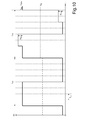
figures 4-13 are six graphs showing corresponding time trends of an electric current flowing across the solenoid valve infigure 3 . - In
figure 1 ,numeral 1 indicates as a whole a vehicle (specifically a car) provided with twofront wheels 2 and tworear drive wheels 3; in front position there is arranged aninternal combustion engine 4 which is provided with acrankshaft 5 and produces a driving torque which is transmitted to therear drive wheels 3 by means of an automaticmanual transmission 6. Thetransmission 6 comprises a dual-clutch gearbox 7 arranged at the rear and adrive shaft 8 which connects thecrankshaft 5 to an input of thegear 7. A self-locking differential 9, from which originates a pair ofaxle shafts 10, each of which is integral with arear drive wheel 3, is connected in cascade to thegear 7. -
Vehicle 1 comprises acontrol unit 11 of theengine 4 which supervises the control of theengine 4, atransmission control unit 12 which supervises the control of thetransmission 6, and aBUS line 13 made according to the CAN (Car Area Network) protocol which is extended to theentire vehicle 1 and allows thecontrol units control unit 11 of theengine 4 and thetransmission control unit 12 are connected to theBUS line 13 and therefore can communicate with each other by means of messages sent over theBUS line 13 itself. Furthermore, thecontrol unit 11 of theengine 4 and thetransmission control unit 12 can be directly connected to each other by means of adedicated synchronization cable 14 which is able to directly transmit a signal from thetransmission control unit 12 to thecontrol unit 11 of theengine 4 without the delays introduced by theBUS line 13. - As shown in
figure 2 , the dual-clutch gearbox 7 comprises a pair ofprimary shafts 15 which are coaxial with each other, independent and fitted within each other. Furthermore, the dual-clutch gearbox 7 comprises twocoaxial clutches 16 arranged in series, each of which is adapted to connect a correspondingprimary shaft 15 to thecrankshaft 5 of theinternal combustion engine 4 by means of the interposition of thetransmission shaft 8. The dual-clutch gear 7 comprises a singlesecondary shaft 17 connected to thedifferential 9 which transmits the motion to therear drive wheels 3; according to an alternative and equivalent embodiment, the dual-clutch gearbox 7 comprises twosecondary shafts 17 which are both connected to thedifferential 9. - The dual-
clutch gearbox 7 has seven forward gears indicated by Roman numerals (first gear I, second gear II, third gear III, fourth gear IV, fifth gear V, sixth gear VI and seventh gear VII) and a reverse gear (indicated by the letter R). Theprimary shaft 15 and thesecondary shaft 17 are mechanically coupled with each other by means of a plurality of pairs of gears, each of which defines a corresponding gear and comprises aprimary gear 18 fitted on theprimary shaft 15 and asecondary gear 19 fitted on thesecondary shaft 17. In order to allow a proper operation of the dual-clutch gearbox 7, all the odd gears (first gear I, third gear III, fifth gear V, seventh gear VII) are coupled to the sameprimary shaft 15, while all the even gears (second gear II, fourth gear IV and sixth gear VI) are coupled to the otherprimary shaft 15. - Each
primary gear 18 is keyed to a correspondingprimary shaft 15 for always rotating integrally with theprimary shaft 15 itself and permanently meshes with the correspondingsecondary gear 19; on the contrary, eachsecondary gear 19 is idly fitted on thesecondary shaft 17. Furthermore, the dual-clutch gearbox 7 comprises fourdouble synchronizers 20, each of which is coaxially fitted to thesecondary shaft 17, it is arranged between twosecondary gears 19, and is adapted to be actuated for alternatively engaging the two correspondingsecondary gears 19 with the secondary shaft 17 (i.e. for alternatively making the two correspondingsecondary gears 19 angularly integral with the secondary shaft 17). In other words, eachsynchronizer 20 may be moved in a direction for engaging asecondary gear 19 with thesecondary shaft 17, or it may be moved in the opposite direction for engaging the othersecondary gear 19 with thesecondary shaft 17. - As shown in
figure 3 , thetransmission 6 comprises a driving hydraulic circuit 21 (only partially shown infigure 3 ) which actuates theclutches 16 and thesynchronizers 20 by means of respective hydraulic servo-controls 22 (only one of which is shown infigure 3 ). Specifically, for the sake of simplicity,figure 3 shows a single hydraulic servo-control 22 which is coupled to aclutch 16 and is provided with athrust chamber 23 which may be filled with oil under pressure; when thethrust chamber 23 is filled with oil under pressure, an axial thrust on the plates of theclutch 16 is generated with an intensity essentially proportional to the pressure P of the oil within thethrust chamber 23. - The
hydraulic circuit 21 comprises areservoir 24 for oil at atmospheric pressure, from which originates aconduit 25 provided with apump 26 and acheck valve 27 for feeding oil under pressure to ahydraulic accumulator 28; thehydraulic accumulator 28 communicates by means of aconduit 29 with an inlet of aproportional solenoid valve 30, from which originate aconduit 31 flowing to thethrust chamber 23 and aconduit 32 flowing to thereservoir 24. In use, thesolenoid valve 30 is able to keep thethrust chamber 23 isolated from thereservoir 24 for keeping the pressure P of the oil in thethrust chamber 23 constant, it is able to connect thethrust chamber 23 to thereservoir 24 for reducing the pressure P of the oil in thethrust chamber 23, and is adapted to connect thethrust chamber 23 to thehydraulic accumulator 28 for increasing the pressure P of the oil in thethrust chamber 23. - The
solenoid valve 30 is provided with acontrol coil 34 which is crossed by an electric current I generated by thetransmission control unit 12 by applying a voltage V variable over time to the ends of thecontrol coil 34. Thetransmission control unit 12 comprises amain microcontroller 35 which communicates with the sensors of the transmission 6 (such as for example apressure sensor 36 which measures the pressure P of the oil within the thrust chamber 23) and with the other components of vehicle 1 (essentially with the engine control unit 11), thus defining a target position for each hydraulic servo-control 22 and therefore translating such target position to a corresponding target current IOBJ (shown infigures 4-13 ) for thecorresponding solenoid valve 30. In order to relieve themain microcontroller 35 from the intensive task of directly implementing the current control of thesolenoid valves 30, themain microcontroller 35 does not directly implement the current control of eachsolenoid valve 30, yet communicates the target current IOBJ to a corresponding supportingmicrocontroller 37 which autonomously achieves the current control of thesolenoid valve 30 for tracking the target current IOBJ received from themain microcontroller 35. In particular, each supportingmicrocontroller 37 tracks the target current IOBJ received from themain microcontroller 35 by means of a feedback control and is therefore provided with a current sensor 38 which measures the intensity of the electric current I which crosses thecontrol coil 34 of thesolenoid valve 30. - Each supporting
microcontroller 37 comprises adigital input 39 which is connected to themain microcontroller 35 for receiving the target current IOBJ to be tracked from themain microcontroller 35 itself. The target current IOBJ to be tracked (i.e. the desired value moment by moment of the current I which crosses thecontrol coil 34 of the solenoid valve 30) is provided by themain microcontroller 35 as a fraction of the maximum value and has a resolution defined by the number of bits of thedigital input 39; for example, an 8-bitdigital input 39 allows a resolution of 1/256, a 9-bitdigital input 39 allows a resolution of 1/512, and a 10-bitdigital input 39 allows a resolution of 1/1024. Consequently, the resolution of the digital input 39 (i.e. the number of bits of the digital input 39) defines the minimum quantization interval Δmin of the target current IOBJ (shown infigures 6-13 ); in other words, the higher the resolution of the digital input 39 (i.e. the greater the number of bits of the digital input 39), the smaller the minimum quantization interval Δmin of the target current IOBJ. For example, an 8-bitdigital input 39 allows a resolution of 1/256 and therefore the minimum variation of the target current IOBJ is 1/256 (i.e. it is not possible to increase or decrease the target current IOBJ by a quantity smaller than 1/256). - As shown in
figure 4 , themain microcontroller 35 uses the control current using dithering, i.e. themain microcontroller 35 overlaps a dithering square wave IDITH, which normally (i.e. under normal conditions) has a zero mean value and has a high oscillation frequency, to each target current IOBJ determined according to the target position; the period TDITH of the dithering square wave is too small to disturb thehydraulic circuit 21 driven by thesolenoid valves 30, but allows to inhibit the occurrence of static friction phenomena within thesolenoid valves 30. In other words, eachsolenoid valve 30 is kept "in fibrillation" with minor fast and small scale oscillations around the target position for preventing the moving parts of thesolenoid valve 30 from "sticking" by increasing the breakout static friction. - As shown in
figure 4 , themain microcontroller 35 determines the target current IOBJ, it determines the dithering square wave IDITH which normally has a zero mean value, and adds the dithering square wave IDITH to the target current IOBJ, for eachsolenoid valve 30; themain microcontroller 35 communicates the addition of the target current IOBJ and the dithering wave square IDITH to thedigital input 39 of the corresponding supportingmicrocontroller 37, such that the supportingmicrocontroller 37 drives thecoil 34 of thesolenoid valve 30 to track such addition. As apparent fromfigure 5 , the supportingmicrocontroller 37 drives thecoil 34 of thesolenoid valve 30 by means of the known control technique called "chopper" which provides the application, to the terminals of thecoil 34 of thesolenoid valve 30, of a positive voltage which determines an increase of the current I which crosses thecoil 34 and alternatively of a zero (or negative) voltage which determines a decrease of the current I which crosses thecoil 34. - The oscillation frequency of the dithering square wave IDITH is chosen such that this oscillation frequency is an integer sub-multiple of (i.e. is smaller than) the maximum variation frequency of the current I across the solenoid valve 30 (i.e. the maximum "speed" by which it is possible to modify the current I across the solenoid valve 30); in other words, the period TDITH of the dithering square wave IDITH is an integer multiple of (i.e. is higher than) the minimum period Tmin by which it is possible to modify the current I across the
solenoid valve 30, as clearly shown infigures 6-13 . In this manner, during a single period TDITH of the dithering square wave IDITH, it is possible to vary the intensity of the current I across thesolenoid valve 30 for multiple times; in the example shown infigures 6-13 , the period TDITH of the dithering square wave IDITH is equal to eight times the minimum period Tmin by which it is possible to modify the current I across the solenoid valve 30 (i.e. the oscillation frequency of the dithering square wave IDITH is equal to 1/8 of the maximum variation frequency of the current I across the solenoid valve 30) and therefore it is possible to vary the current I across thesolenoid valve 30 for eight times at every period TDITH of the dithering square wave IDITH · - Due to the fact that during a single period TDITH of the dithering square wave IDITH it is possible to vary the intensity of the current I across the
solenoid valve 30 for multiple times, it is possible to vary the amplitude of the dithering square wave IDITH for a fraction of the period TDITH of the dithering square wave IDITH itself and by an amount equal to the minimum quantization interval Δmin of the target current IOBJ for temporarily determining a deviation of the mean value of the dithering square wave IDITH with respect to zero and therefore obtaining a corresponding variation of the mean value of the target current IOBJ by an amount equal to a fraction of the minimum quantization interval Δmin. - In
figure 6 , the dithering square wave IDITH of the first period is identical to the dithering square wave IDITH of the second period, and therefore the mean value of the target current IOBJ remains constant between the first period and the second period. - In
figure 7 , the dithering square wave IDITH of the second period differs from the dithering square wave IDITH of the first period in that, during 1/4 of the period TDITH, the dithering square wave IDITH of the second period is increased by an amount equal to the minimum quantization interval Δmin for 1/4 of the period TDITH; in this manner, the mean value of the target current IOBJ increases by 1/4 of the minimum quantization interval Δmin between the first period and the second period. As shown infigure 7 , the increase of the dithering square wave IDITH of the second period is distributed half in a first positive half period and half in a second negative period; as shown infigures 8 and9 , it is also possible to set all the increase of the dithering square wave IDITH of the second period in a single half period (in the first half period as shown infigure 8 and in the second half period as shown infigure 9 ). - In
figure 10 , the dithering square wave IDITH of the second period differs from the dithering square wave IDITH of the first period in that, during 2/4 of the period TDITH, the dithering square wave IDITH of the second period is increased by an amount equal to the minimum quantization interval Δmin; in this manner, the mean value of the target current IOBJ increases by 2/4 of the minimum quantization interval Δmin between the first period and the second period. - In
figure 11 , the dithering square wave IDITH of the second period differs from the dithering square wave IDITH of the first period in that, during 3/4 of the period TDITH, the dithering square wave IDITH of the second period is increased by an amount equal to the minimum quantization interval Δmin; in this manner, the mean value of the target current IOBJ increases by 3/4 of the minimum quantization interval Δmin between the first period and the second period. - In
figure 12 , the dithering square wave IDITH of the second period differs from the dithering square wave IDITH of the first period in that, during 5/8 of the period TDITH, the dithering square wave IDITH of the second period is increased by an amount equal to the minimum quantization interval Δmin; in this manner, the mean value of the target current IOBJ increases by 5/8 of the minimum quantization interval Δmin between the first period and the second period. - In
figure 13 , the dithering square wave IDITH of the second period differs from the dithering square wave IDITH of the first period in that, during 7/8 of the period TDITH, the dithering square wave IDITH of the second period is increased by an amount equal to the minimum quantization interval Δmin; in this manner, the mean value of the target current IOBJ increases by 7/8 of the minimum quantization interval Δmin between the first period and the second period. - As set forth above, it is apparent that it is possible to obtain a variation of the mean value of the target current IOBJ by an amount equal to a fraction of the minimum quantization interval Δmin, and it is therefore possible to effectively increase the effective resolution on the control of the target current IOBJ.
- The above-described control method of the position of a
solenoid valve 30 using dithering has many advantages. - Firstly, the above-described control method of the position of a
solenoid valve 30 using dithering allows to increase the effective resolution of the control of the target current IOBJ which is higher than the "hardware" resolution (i.e. defined by the number of bits of thedigital input 39 of the corresponding supporting microcontroller 37). In other words, by means of a moderate complication of the software control, it is possible to increase the effective resolution of the control of the target current IOBJ as compared with the limits defined by the "hardware". - Furthermore, the above-described control method of the position of a
solenoid valve 30 using dithering is simple and cost-effective to be implemented, since it does not require the installation of additional physical components and does not involve an expansion of thetransmission control unit 12 as it does not require a significant additional processing power.
Claims (5)
- Control method of the position of a solenoid valve (30) using dithering; the control method comprises the steps of:determining a target current (IOBJ) through the solenoid valve (30) that is expressed in digital form with a given minimum quantization interval (Δmin);adding to the target current (IOBJ) a dithering square wave (IDITH) which has a high frequency of oscillation; andcontrolling the voltage (V) applied to the solenoid valve (30) to make the current (I) through the solenoid (30) follow the target current (IOBJ) added to the dithering square wave (IDITH);the control method is characterized in that it comprises the additional steps of:jiggling the dithering square wave (IDITH) with a frequency that is a sub-multiple of the maximum frequency of variation of the current (I) through the solenoid valve (30); andvarying the amplitude of the dithering square wave (IDITH) for a fraction of the period (TDITH) of the dithering square wave (IDITH) and by an amount equal to the minimum quantization interval (Δmin) of the target current (IOBJ) to temporarily determine a deviation of the mean value of dithering square wave (IDITH) compared to zero and therefore get a corresponding variation of the mean value of the target current (IOBJ) by an amount equal to a fraction of the minimum quantization interval (Δmin).
- Control method according to claim 1 comprising the additional steps of:determining the target current (IOBJ) and the dithering square wave (IDITH) using a primary microcontroller (35); andtransmitting in digital form the target current (IOBJ) added to the dithering square-wave (IDITH) to a support microcontroller (37) that controls the voltage (V) applied to the solenoid valve (30) to make the current (I) through the solenoid valve (30) follow the target current (IOBJ) added to the dithering square wave (IDITH) .
- Control method according to claim 1 or 2, wherein the solenoid valve (30) is part of a driving hydraulic circuit (21) that actuates an automatic manual transmission (6).
- Control method according to claim 3, wherein the solenoid valve (30) drives a clutch (16) of the automatic manual transmission (6).
- Automatic manual transmission (6) for a vehicle and comprising:a driving hydraulic circuit (21) having at least one solenoid valve(30); anda control unit (12) of the transmission which controls the position of the solenoid valve(30) using the control method using dithering according to one of the claims from 1 to 3.
Applications Claiming Priority (1)
| Application Number | Priority Date | Filing Date | Title |
|---|---|---|---|
| ITBO2010A000140A IT1398247B1 (en) | 2010-03-09 | 2010-03-09 | METHOD OF CONTROL WITH DITHERING OF THE POSITION OF A SOLENOID VALVE |
Publications (2)
| Publication Number | Publication Date |
|---|---|
| EP2365232A1 true EP2365232A1 (en) | 2011-09-14 |
| EP2365232B1 EP2365232B1 (en) | 2013-01-30 |
Family
ID=43028977
Family Applications (1)
| Application Number | Title | Priority Date | Filing Date |
|---|---|---|---|
| EP11157558A Active EP2365232B1 (en) | 2010-03-09 | 2011-03-09 | Control method of the position of a solenoid valve using dithering |
Country Status (3)
| Country | Link |
|---|---|
| US (1) | US8571769B2 (en) |
| EP (1) | EP2365232B1 (en) |
| IT (1) | IT1398247B1 (en) |
Cited By (3)
| Publication number | Priority date | Publication date | Assignee | Title |
|---|---|---|---|---|
| KR20190048703A (en) * | 2017-10-31 | 2019-05-09 | 현대 파워텍 주식회사 | Apparatus for controlling transmission of vehicle and method thereof |
| CN111750159A (en) * | 2020-07-09 | 2020-10-09 | 四川航天烽火伺服控制技术有限公司 | Novel electromagnetic valve capable of improving thrust of valve element |
| EP3904729A1 (en) * | 2020-04-27 | 2021-11-03 | Mazda Motor Corporation | Hydraulic pressure control device, vehicle, and method of controlling automatic transmission |
Families Citing this family (2)
| Publication number | Priority date | Publication date | Assignee | Title |
|---|---|---|---|---|
| JP6622483B2 (en) * | 2015-05-11 | 2019-12-18 | 株式会社デンソー | Hydraulic control device |
| US11459076B1 (en) * | 2020-01-03 | 2022-10-04 | Brunswick Corporation | Systems and methods for controlling transmission valves in a marine propulsion device |
Citations (4)
| Publication number | Priority date | Publication date | Assignee | Title |
|---|---|---|---|---|
| JPH10198431A (en) * | 1997-01-10 | 1998-07-31 | Mitsubishi Heavy Ind Ltd | Method and device for controlling proportional solenoid valve |
| US20060011878A1 (en) * | 2004-07-15 | 2006-01-19 | Ford Motor Company | A control method and controller for a solenoid-operated electrohydraulic control valve |
| WO2006037715A1 (en) * | 2004-10-06 | 2006-04-13 | Siemens Aktiengesellschaft | Method and device for determining a pwm signal on which a dither frequency is superimposed in order to control a solenoid valve |
| JP2009228794A (en) * | 2008-03-24 | 2009-10-08 | Kubota Corp | Hydraulic system of working machine |
Family Cites Families (2)
| Publication number | Priority date | Publication date | Assignee | Title |
|---|---|---|---|---|
| DE102006012657A1 (en) * | 2006-03-20 | 2007-09-27 | Siemens Ag | Control unit with a controller for controlling the electrical coil current of a control solenoid valve |
| DE102008000304B4 (en) * | 2008-02-15 | 2017-09-14 | Zf Friedrichshafen Ag | Method for operating a valve device of a transmission device |
-
2010
- 2010-03-09 IT ITBO2010A000140A patent/IT1398247B1/en active
-
2011
- 2011-03-08 US US13/043,321 patent/US8571769B2/en active Active
- 2011-03-09 EP EP11157558A patent/EP2365232B1/en active Active
Patent Citations (4)
| Publication number | Priority date | Publication date | Assignee | Title |
|---|---|---|---|---|
| JPH10198431A (en) * | 1997-01-10 | 1998-07-31 | Mitsubishi Heavy Ind Ltd | Method and device for controlling proportional solenoid valve |
| US20060011878A1 (en) * | 2004-07-15 | 2006-01-19 | Ford Motor Company | A control method and controller for a solenoid-operated electrohydraulic control valve |
| WO2006037715A1 (en) * | 2004-10-06 | 2006-04-13 | Siemens Aktiengesellschaft | Method and device for determining a pwm signal on which a dither frequency is superimposed in order to control a solenoid valve |
| JP2009228794A (en) * | 2008-03-24 | 2009-10-08 | Kubota Corp | Hydraulic system of working machine |
Cited By (5)
| Publication number | Priority date | Publication date | Assignee | Title |
|---|---|---|---|---|
| KR20190048703A (en) * | 2017-10-31 | 2019-05-09 | 현대 파워텍 주식회사 | Apparatus for controlling transmission of vehicle and method thereof |
| EP3904729A1 (en) * | 2020-04-27 | 2021-11-03 | Mazda Motor Corporation | Hydraulic pressure control device, vehicle, and method of controlling automatic transmission |
| US11624412B2 (en) | 2020-04-27 | 2023-04-11 | Mazda Motor Corporation | Hydraulic pressure control device |
| CN111750159A (en) * | 2020-07-09 | 2020-10-09 | 四川航天烽火伺服控制技术有限公司 | Novel electromagnetic valve capable of improving thrust of valve element |
| CN111750159B (en) * | 2020-07-09 | 2022-04-12 | 四川航天烽火伺服控制技术有限公司 | Novel electromagnetic valve capable of improving thrust of valve element |
Also Published As
| Publication number | Publication date |
|---|---|
| US8571769B2 (en) | 2013-10-29 |
| ITBO20100140A1 (en) | 2011-09-10 |
| US20110246035A1 (en) | 2011-10-06 |
| IT1398247B1 (en) | 2013-02-22 |
| EP2365232B1 (en) | 2013-01-30 |
Similar Documents
| Publication | Publication Date | Title |
|---|---|---|
| EP2365232B1 (en) | Control method of the position of a solenoid valve using dithering | |
| US7131932B2 (en) | Method for determing a transmittable torque of a clutch in an automatic transmission of a motor vehicle | |
| US9517763B2 (en) | Control systems and methods for transmission of hybrid power vehicle | |
| CN101029678A (en) | Transmission with torque sensors and method of controlling a transmission | |
| JP2004251455A (en) | Method for controlling double clutch transmission | |
| CN104019193A (en) | Torque return difference type two-gear automatic transmission and gear shifting control method | |
| CN105697588B (en) | Electronic control of manual transmission clutch | |
| EP3207290B1 (en) | Dual motor drive unit and method of drivingly engaging a first motor of a dual motor drive unit with an output shaft | |
| CN105221739A (en) | Control dual clutch transmission and enter gear, the method for shifting gears and hydraulic control system | |
| CN106911269B (en) | Control of an electric motor | |
| EP2458249B1 (en) | Method of controlling a double clutch in a vehicle transmission, and clutch control system for controlling a double clutch | |
| US9488267B2 (en) | Line pressure control with input shaft torque measurement | |
| CN102818007A (en) | Active damping tip-in clutch control of a vehicle transmission | |
| KR102110238B1 (en) | Method for correcting a drag torque curve of at least one rotatably mounted machine element | |
| US8423252B2 (en) | Control method of shifting gear in an automatic manual transmission | |
| US8147376B2 (en) | Construction vehicle | |
| CN111963673B (en) | Self-learning method and system for half-joint point of wet-type double-clutch transmission | |
| JP2006522905A (en) | Transmission actuator and control method thereof | |
| GB2273321A (en) | An epicyclic change-speed gearbox has pressure in an outgoing clutch/brake switched off when a variable reference is reached | |
| US10005467B2 (en) | Method of controlling a dual clutch transmission | |
| JP2020101091A (en) | Control device, and control method | |
| US20070155585A1 (en) | Method of controlling a vehicle transmission | |
| US11614161B2 (en) | Method for determining reference values of a sensor | |
| US10451173B2 (en) | Control device for dual-clutch transmission | |
| RU2552787C1 (en) | Pre-selective gearbox |
Legal Events
| Date | Code | Title | Description |
|---|---|---|---|
| PUAI | Public reference made under article 153(3) epc to a published international application that has entered the european phase |
Free format text: ORIGINAL CODE: 0009012 |
|
| AK | Designated contracting states |
Kind code of ref document: A1 Designated state(s): AL AT BE BG CH CY CZ DE DK EE ES FI FR GB GR HR HU IE IS IT LI LT LU LV MC MK MT NL NO PL PT RO RS SE SI SK SM TR |
|
| AX | Request for extension of the european patent |
Extension state: BA ME |
|
| 17P | Request for examination filed |
Effective date: 20120314 |
|
| GRAP | Despatch of communication of intention to grant a patent |
Free format text: ORIGINAL CODE: EPIDOSNIGR1 |
|
| RIC1 | Information provided on ipc code assigned before grant |
Ipc: G05D 16/20 20060101ALI20120731BHEP Ipc: F16H 61/02 20060101AFI20120731BHEP Ipc: F16K 31/06 20060101ALI20120731BHEP |
|
| GRAS | Grant fee paid |
Free format text: ORIGINAL CODE: EPIDOSNIGR3 |
|
| GRAA | (expected) grant |
Free format text: ORIGINAL CODE: 0009210 |
|
| AK | Designated contracting states |
Kind code of ref document: B1 Designated state(s): AL AT BE BG CH CY CZ DE DK EE ES FI FR GB GR HR HU IE IS IT LI LT LU LV MC MK MT NL NO PL PT RO RS SE SI SK SM TR |
|
| REG | Reference to a national code |
Ref country code: GB Ref legal event code: FG4D |
|
| REG | Reference to a national code |
Ref country code: CH Ref legal event code: EP |
|
| REG | Reference to a national code |
Ref country code: AT Ref legal event code: REF Ref document number: 595771 Country of ref document: AT Kind code of ref document: T Effective date: 20130215 Ref country code: CH Ref legal event code: EP |
|
| REG | Reference to a national code |
Ref country code: IE Ref legal event code: FG4D |
|
| REG | Reference to a national code |
Ref country code: DE Ref legal event code: R096 Ref document number: 602011000862 Country of ref document: DE Effective date: 20130321 |
|
| REG | Reference to a national code |
Ref country code: AT Ref legal event code: MK05 Ref document number: 595771 Country of ref document: AT Kind code of ref document: T Effective date: 20130130 |
|
| REG | Reference to a national code |
Ref country code: LT Ref legal event code: MG4D |
|
| REG | Reference to a national code |
Ref country code: NL Ref legal event code: VDEP Effective date: 20130130 |
|
| PG25 | Lapsed in a contracting state [announced via postgrant information from national office to epo] |
Ref country code: ES Free format text: LAPSE BECAUSE OF FAILURE TO SUBMIT A TRANSLATION OF THE DESCRIPTION OR TO PAY THE FEE WITHIN THE PRESCRIBED TIME-LIMIT Effective date: 20130511 Ref country code: BE Free format text: LAPSE BECAUSE OF FAILURE TO SUBMIT A TRANSLATION OF THE DESCRIPTION OR TO PAY THE FEE WITHIN THE PRESCRIBED TIME-LIMIT Effective date: 20130130 Ref country code: AT Free format text: LAPSE BECAUSE OF FAILURE TO SUBMIT A TRANSLATION OF THE DESCRIPTION OR TO PAY THE FEE WITHIN THE PRESCRIBED TIME-LIMIT Effective date: 20130130 Ref country code: SE Free format text: LAPSE BECAUSE OF FAILURE TO SUBMIT A TRANSLATION OF THE DESCRIPTION OR TO PAY THE FEE WITHIN THE PRESCRIBED TIME-LIMIT Effective date: 20130130 Ref country code: IS Free format text: LAPSE BECAUSE OF FAILURE TO SUBMIT A TRANSLATION OF THE DESCRIPTION OR TO PAY THE FEE WITHIN THE PRESCRIBED TIME-LIMIT Effective date: 20130530 Ref country code: LT Free format text: LAPSE BECAUSE OF FAILURE TO SUBMIT A TRANSLATION OF THE DESCRIPTION OR TO PAY THE FEE WITHIN THE PRESCRIBED TIME-LIMIT Effective date: 20130130 Ref country code: NO Free format text: LAPSE BECAUSE OF FAILURE TO SUBMIT A TRANSLATION OF THE DESCRIPTION OR TO PAY THE FEE WITHIN THE PRESCRIBED TIME-LIMIT Effective date: 20130430 Ref country code: BG Free format text: LAPSE BECAUSE OF FAILURE TO SUBMIT A TRANSLATION OF THE DESCRIPTION OR TO PAY THE FEE WITHIN THE PRESCRIBED TIME-LIMIT Effective date: 20130430 |
|
| PG25 | Lapsed in a contracting state [announced via postgrant information from national office to epo] |
Ref country code: NL Free format text: LAPSE BECAUSE OF FAILURE TO SUBMIT A TRANSLATION OF THE DESCRIPTION OR TO PAY THE FEE WITHIN THE PRESCRIBED TIME-LIMIT Effective date: 20130130 Ref country code: FI Free format text: LAPSE BECAUSE OF FAILURE TO SUBMIT A TRANSLATION OF THE DESCRIPTION OR TO PAY THE FEE WITHIN THE PRESCRIBED TIME-LIMIT Effective date: 20130130 Ref country code: PT Free format text: LAPSE BECAUSE OF FAILURE TO SUBMIT A TRANSLATION OF THE DESCRIPTION OR TO PAY THE FEE WITHIN THE PRESCRIBED TIME-LIMIT Effective date: 20130530 Ref country code: PL Free format text: LAPSE BECAUSE OF FAILURE TO SUBMIT A TRANSLATION OF THE DESCRIPTION OR TO PAY THE FEE WITHIN THE PRESCRIBED TIME-LIMIT Effective date: 20130130 Ref country code: GR Free format text: LAPSE BECAUSE OF FAILURE TO SUBMIT A TRANSLATION OF THE DESCRIPTION OR TO PAY THE FEE WITHIN THE PRESCRIBED TIME-LIMIT Effective date: 20130501 Ref country code: LV Free format text: LAPSE BECAUSE OF FAILURE TO SUBMIT A TRANSLATION OF THE DESCRIPTION OR TO PAY THE FEE WITHIN THE PRESCRIBED TIME-LIMIT Effective date: 20130130 Ref country code: SI Free format text: LAPSE BECAUSE OF FAILURE TO SUBMIT A TRANSLATION OF THE DESCRIPTION OR TO PAY THE FEE WITHIN THE PRESCRIBED TIME-LIMIT Effective date: 20130130 |
|
| PG25 | Lapsed in a contracting state [announced via postgrant information from national office to epo] |
Ref country code: RS Free format text: LAPSE BECAUSE OF FAILURE TO SUBMIT A TRANSLATION OF THE DESCRIPTION OR TO PAY THE FEE WITHIN THE PRESCRIBED TIME-LIMIT Effective date: 20130130 Ref country code: HR Free format text: LAPSE BECAUSE OF FAILURE TO SUBMIT A TRANSLATION OF THE DESCRIPTION OR TO PAY THE FEE WITHIN THE PRESCRIBED TIME-LIMIT Effective date: 20130130 |
|
| PG25 | Lapsed in a contracting state [announced via postgrant information from national office to epo] |
Ref country code: RO Free format text: LAPSE BECAUSE OF FAILURE TO SUBMIT A TRANSLATION OF THE DESCRIPTION OR TO PAY THE FEE WITHIN THE PRESCRIBED TIME-LIMIT Effective date: 20130130 Ref country code: SK Free format text: LAPSE BECAUSE OF FAILURE TO SUBMIT A TRANSLATION OF THE DESCRIPTION OR TO PAY THE FEE WITHIN THE PRESCRIBED TIME-LIMIT Effective date: 20130130 Ref country code: CZ Free format text: LAPSE BECAUSE OF FAILURE TO SUBMIT A TRANSLATION OF THE DESCRIPTION OR TO PAY THE FEE WITHIN THE PRESCRIBED TIME-LIMIT Effective date: 20130130 Ref country code: MC Free format text: LAPSE BECAUSE OF NON-PAYMENT OF DUE FEES Effective date: 20130331 Ref country code: EE Free format text: LAPSE BECAUSE OF FAILURE TO SUBMIT A TRANSLATION OF THE DESCRIPTION OR TO PAY THE FEE WITHIN THE PRESCRIBED TIME-LIMIT Effective date: 20130130 Ref country code: DK Free format text: LAPSE BECAUSE OF FAILURE TO SUBMIT A TRANSLATION OF THE DESCRIPTION OR TO PAY THE FEE WITHIN THE PRESCRIBED TIME-LIMIT Effective date: 20130130 |
|
| PG25 | Lapsed in a contracting state [announced via postgrant information from national office to epo] |
Ref country code: CY Free format text: LAPSE BECAUSE OF FAILURE TO SUBMIT A TRANSLATION OF THE DESCRIPTION OR TO PAY THE FEE WITHIN THE PRESCRIBED TIME-LIMIT Effective date: 20130130 |
|
| PLBE | No opposition filed within time limit |
Free format text: ORIGINAL CODE: 0009261 |
|
| STAA | Information on the status of an ep patent application or granted ep patent |
Free format text: STATUS: NO OPPOSITION FILED WITHIN TIME LIMIT |
|
| REG | Reference to a national code |
Ref country code: FR Ref legal event code: ST Effective date: 20131129 |
|
| REG | Reference to a national code |
Ref country code: IE Ref legal event code: MM4A |
|
| 26N | No opposition filed |
Effective date: 20131031 |
|
| PG25 | Lapsed in a contracting state [announced via postgrant information from national office to epo] |
Ref country code: AL Free format text: LAPSE BECAUSE OF FAILURE TO SUBMIT A TRANSLATION OF THE DESCRIPTION OR TO PAY THE FEE WITHIN THE PRESCRIBED TIME-LIMIT Effective date: 20130130 Ref country code: IE Free format text: LAPSE BECAUSE OF NON-PAYMENT OF DUE FEES Effective date: 20130309 Ref country code: FR Free format text: LAPSE BECAUSE OF NON-PAYMENT OF DUE FEES Effective date: 20130402 |
|
| REG | Reference to a national code |
Ref country code: DE Ref legal event code: R097 Ref document number: 602011000862 Country of ref document: DE Effective date: 20131031 |
|
| PG25 | Lapsed in a contracting state [announced via postgrant information from national office to epo] |
Ref country code: MT Free format text: LAPSE BECAUSE OF FAILURE TO SUBMIT A TRANSLATION OF THE DESCRIPTION OR TO PAY THE FEE WITHIN THE PRESCRIBED TIME-LIMIT Effective date: 20130130 |
|
| REG | Reference to a national code |
Ref country code: CH Ref legal event code: PL |
|
| PG25 | Lapsed in a contracting state [announced via postgrant information from national office to epo] |
Ref country code: CH Free format text: LAPSE BECAUSE OF NON-PAYMENT OF DUE FEES Effective date: 20140331 Ref country code: LI Free format text: LAPSE BECAUSE OF NON-PAYMENT OF DUE FEES Effective date: 20140331 |
|
| PG25 | Lapsed in a contracting state [announced via postgrant information from national office to epo] |
Ref country code: SM Free format text: LAPSE BECAUSE OF FAILURE TO SUBMIT A TRANSLATION OF THE DESCRIPTION OR TO PAY THE FEE WITHIN THE PRESCRIBED TIME-LIMIT Effective date: 20130130 |
|
| PG25 | Lapsed in a contracting state [announced via postgrant information from national office to epo] |
Ref country code: TR Free format text: LAPSE BECAUSE OF FAILURE TO SUBMIT A TRANSLATION OF THE DESCRIPTION OR TO PAY THE FEE WITHIN THE PRESCRIBED TIME-LIMIT Effective date: 20130130 |
|
| PG25 | Lapsed in a contracting state [announced via postgrant information from national office to epo] |
Ref country code: MK Free format text: LAPSE BECAUSE OF FAILURE TO SUBMIT A TRANSLATION OF THE DESCRIPTION OR TO PAY THE FEE WITHIN THE PRESCRIBED TIME-LIMIT Effective date: 20130130 Ref country code: LU Free format text: LAPSE BECAUSE OF NON-PAYMENT OF DUE FEES Effective date: 20130309 Ref country code: HU Free format text: LAPSE BECAUSE OF FAILURE TO SUBMIT A TRANSLATION OF THE DESCRIPTION OR TO PAY THE FEE WITHIN THE PRESCRIBED TIME-LIMIT; INVALID AB INITIO Effective date: 20110309 |
|
| PGFP | Annual fee paid to national office [announced via postgrant information from national office to epo] |
Ref country code: IT Payment date: 20230317 Year of fee payment: 13 Ref country code: GB Payment date: 20230321 Year of fee payment: 13 Ref country code: DE Payment date: 20230328 Year of fee payment: 13 |
|
| P01 | Opt-out of the competence of the unified patent court (upc) registered |
Effective date: 20230525 |