EP2365195A1 - Exhaust gas treatment apparatus for working machine - Google Patents
Exhaust gas treatment apparatus for working machine Download PDFInfo
- Publication number
- EP2365195A1 EP2365195A1 EP11156226A EP11156226A EP2365195A1 EP 2365195 A1 EP2365195 A1 EP 2365195A1 EP 11156226 A EP11156226 A EP 11156226A EP 11156226 A EP11156226 A EP 11156226A EP 2365195 A1 EP2365195 A1 EP 2365195A1
- Authority
- EP
- European Patent Office
- Prior art keywords
- pressure oil
- valve
- exhaust gas
- open
- pilot
- Prior art date
- Legal status (The legal status is an assumption and is not a legal conclusion. Google has not performed a legal analysis and makes no representation as to the accuracy of the status listed.)
- Granted
Links
Images


Classifications
-
- F—MECHANICAL ENGINEERING; LIGHTING; HEATING; WEAPONS; BLASTING
- F01—MACHINES OR ENGINES IN GENERAL; ENGINE PLANTS IN GENERAL; STEAM ENGINES
- F01N—GAS-FLOW SILENCERS OR EXHAUST APPARATUS FOR MACHINES OR ENGINES IN GENERAL; GAS-FLOW SILENCERS OR EXHAUST APPARATUS FOR INTERNAL COMBUSTION ENGINES
- F01N9/00—Electrical control of exhaust gas treating apparatus
- F01N9/002—Electrical control of exhaust gas treating apparatus of filter regeneration, e.g. detection of clogging
-
- E—FIXED CONSTRUCTIONS
- E02—HYDRAULIC ENGINEERING; FOUNDATIONS; SOIL SHIFTING
- E02F—DREDGING; SOIL-SHIFTING
- E02F9/00—Component parts of dredgers or soil-shifting machines, not restricted to one of the kinds covered by groups E02F3/00 - E02F7/00
- E02F9/20—Drives; Control devices
- E02F9/2058—Electric or electro-mechanical or mechanical control devices of vehicle sub-units
- E02F9/2062—Control of propulsion units
- E02F9/2066—Control of propulsion units of the type combustion engines
-
- E—FIXED CONSTRUCTIONS
- E02—HYDRAULIC ENGINEERING; FOUNDATIONS; SOIL SHIFTING
- E02F—DREDGING; SOIL-SHIFTING
- E02F9/00—Component parts of dredgers or soil-shifting machines, not restricted to one of the kinds covered by groups E02F3/00 - E02F7/00
- E02F9/20—Drives; Control devices
- E02F9/22—Hydraulic or pneumatic drives
- E02F9/2221—Control of flow rate; Load sensing arrangements
- E02F9/2225—Control of flow rate; Load sensing arrangements using pressure-compensating valves
- E02F9/2228—Control of flow rate; Load sensing arrangements using pressure-compensating valves including an electronic controller
-
- F—MECHANICAL ENGINEERING; LIGHTING; HEATING; WEAPONS; BLASTING
- F01—MACHINES OR ENGINES IN GENERAL; ENGINE PLANTS IN GENERAL; STEAM ENGINES
- F01N—GAS-FLOW SILENCERS OR EXHAUST APPARATUS FOR MACHINES OR ENGINES IN GENERAL; GAS-FLOW SILENCERS OR EXHAUST APPARATUS FOR INTERNAL COMBUSTION ENGINES
- F01N2390/00—Arrangements for controlling or regulating exhaust apparatus
- F01N2390/02—Arrangements for controlling or regulating exhaust apparatus using electric components only
-
- F—MECHANICAL ENGINEERING; LIGHTING; HEATING; WEAPONS; BLASTING
- F01—MACHINES OR ENGINES IN GENERAL; ENGINE PLANTS IN GENERAL; STEAM ENGINES
- F01N—GAS-FLOW SILENCERS OR EXHAUST APPARATUS FOR MACHINES OR ENGINES IN GENERAL; GAS-FLOW SILENCERS OR EXHAUST APPARATUS FOR INTERNAL COMBUSTION ENGINES
- F01N2590/00—Exhaust or silencing apparatus adapted to particular use, e.g. for military applications, airplanes, submarines
- F01N2590/08—Exhaust or silencing apparatus adapted to particular use, e.g. for military applications, airplanes, submarines for heavy duty applications, e.g. trucks, buses, tractors, locomotives
-
- F—MECHANICAL ENGINEERING; LIGHTING; HEATING; WEAPONS; BLASTING
- F01—MACHINES OR ENGINES IN GENERAL; ENGINE PLANTS IN GENERAL; STEAM ENGINES
- F01N—GAS-FLOW SILENCERS OR EXHAUST APPARATUS FOR MACHINES OR ENGINES IN GENERAL; GAS-FLOW SILENCERS OR EXHAUST APPARATUS FOR INTERNAL COMBUSTION ENGINES
- F01N2900/00—Details of electrical control or of the monitoring of the exhaust gas treating apparatus
- F01N2900/06—Parameters used for exhaust control or diagnosing
- F01N2900/12—Parameters used for exhaust control or diagnosing said parameters being related to the vehicle exterior
-
- Y—GENERAL TAGGING OF NEW TECHNOLOGICAL DEVELOPMENTS; GENERAL TAGGING OF CROSS-SECTIONAL TECHNOLOGIES SPANNING OVER SEVERAL SECTIONS OF THE IPC; TECHNICAL SUBJECTS COVERED BY FORMER USPC CROSS-REFERENCE ART COLLECTIONS [XRACs] AND DIGESTS
- Y02—TECHNOLOGIES OR APPLICATIONS FOR MITIGATION OR ADAPTATION AGAINST CLIMATE CHANGE
- Y02T—CLIMATE CHANGE MITIGATION TECHNOLOGIES RELATED TO TRANSPORTATION
- Y02T10/00—Road transport of goods or passengers
- Y02T10/10—Internal combustion engine [ICE] based vehicles
- Y02T10/40—Engine management systems
Definitions
- This invention relates to an exhaust gas treatment apparatus for a working machine such as a hydraulic excavator which enables a specific process in an exhaust gas treatment section to be carried out, by raising the output of an engine by increasing the hydraulic load on the working machine that is hydraulically driven.
- Fig. 5 is a circuit diagram showing an example of an exhaust gas treatment apparatus for a working machine according to the related art.
- this exhaust gas treatment apparatus includes a hydraulic pump 8 driven by an engine 5a, an actuator 4a that is actuated upon supply of pressure oil from the hydraulic pump 8, a directional control valve 14 that controls the flow of pressure oil supplied to the actuator 4a, and an operating device 19 having an operating lever 19a operated to switch the directional control valve 14.
- the exhaust gas treatment apparatus also includes a pilot pump 16 that supplies pressure oil to the operating device 19, an open/close valve 13 that is arranged downstream of the directional control valve 14, and controls the opening and closing of a channel connected to a tank 25, a control valve 15 that is arranged between the open/close valve 13 and the pilot pump 16, and controls the open/close valve 13 to an open position 13a or a close position 13b, and a lock valve 17 that is arranged between the pilot pump 16 and the operating device 19, and can be switched between a lock position 17c for keeping actuation of the actuator 4a disabled, and an unlock position 17b for enabling actuation of the actuator 4a.
- the hydraulic pump 8, the pilot pump 16, and the lock valve 17 are each connected to the tank 25.
- a relief valve 20 is provided in a pipe 26 connecting between the pilot pump 16 and the lock valve 17. When the pilot pressure oil supplied from the pilot pump 16 becomes excessive, the relief valve 20 relieves the excess pilot pressure oil to the tank 25.
- the exhaust gas treatment apparatus includes an exhaust gas treatment section 11 that is attached to the exhaust port 10 of the engine 5a, and treats exhaust gas emitted from the engine 5a, a detecting section 12 that detects when a specific process that raises the exhaust temperature of the exhaust gas treatment section 11 becomes necessary, and outputs a signal for setting the control valve 15 to an open position 15b, and a controller 18 that controls the control valve 15.
- the exhaust gas treatment section 11 has in the inside a filter (not shown) with an oxidation catalyst such as platinum.
- an oxidation catalyst such as platinum.
- the exhaust gas treatment section 11 changes the unburned matter into harmless matter such as water or carbon dioxide and then emits the harmless matter.
- the oxidation catalyst such as platinum provided in the filter does not exert an effective catalytic effect unless its temperature becomes equal to or higher than a predetermined temperature specific to the oxidation catalyst. Accordingly, if the temperature of exhaust gas flowing into the exhaust gas treatment section 11 is lower than this specific predetermined temperature, the captured unburned matter builds up on the filter without being oxidized.
- the detecting section 12 includes an exhaust pressure sensor that detects the pressure of exhaust gas flowing into the exhaust gas treatment section 11, and also a temperature sensor that detects the temperature of exhaust gas.
- the detecting section 12 detects by the exhaust pressure sensor that the pressure on the upstream side of the oxidation catalyst has become high, and also exhaust temperature is low, the detecting section 12 outputs a signal indicating the start of the above-mentioned specific process.
- an exhaust gas treatment apparatus for a working machine which performs such a specific process
- the detecting section 12 is provided on the inlet side of an exhaust gas control device provided in a connected fashion to the exhaust port 10 of the engine 5a, in other words, the exhaust gas treatment section 11, and detects the exhaust resistance of the engine 5a
- the controller 18 includes the function of raising the discharge rate and discharge pressure of pressure oil discharged from the hydraulic pump 8, in other words, raising the output of the engine 5a when the exhaust resistance measured by the detecting section 12 becomes a predetermined preset value or more, thereby raising the temperature of exhaust gas from the engine 5a to a sufficient temperature for enabling the exhaust gas treatment section 11 to exert its exhaust gas treatment capability properly (see, for example, Japanese Patent No. 3073380 ).
- the operating lever 19a of the operating device 19 is attached with a neutral detection switch 19b for detecting the neutral state of the directional control valve 14.
- the neutral state of the directional control valve 14 is electrically detected by closing of the circuit of the neutral detection switch 19b, and the above-mentioned specific process is performed only when the directional control valve 14 is in the neutral state, thereby preventing the actuator 4a from operating in a manner not intended by the operator.
- the controller 18 when the controller 18 receives a signal indicating the neutral state of the directional control valve 14 on the basis of the neutral detection switch 19b, and the exhaust resistance measured by the detecting section 12 becomes equal to or higher than a predetermined preset value, the controller 18 switches the control valve 15 to the open position 15b that is the upper position, thereby causing the pilot pressure oil from the pilot pump 16 to be supplied to a control part on the right side of the open/close valve 13 via the control valve 15.
- the open/close valve 13 is switched to the close position 13b that is the right position. Then, the pipe line leading to the tank 25 is closed, and the discharge pressure of the pressure oil discharged from the hydraulic pump 8 rises simultaneously.
- the controller 18 performs the above-mentioned specific process in which when the exhaust resistance measured by the detecting section 12 becomes a predetermined preset value or more, the control valve 15 is switched to the open position 15b that is the upper position to thereby cause the pilot pressure oil from the pilot pump 16 to be supplied to the control part on the right side of the open/close valve 13 via the control valve 15, and the open/close valve 13 is switched to the close position 13b that is the right position to thereby raise the discharge pressure of the pressure oil discharged from the hydraulic pump 8 simultaneously. Consequently, excess pressure oil is supplied to the actuator 4a while the directional control valve 14 is being switched with the operating lever 19a of the operating device 19, so the speed of the actuator 4a increases, resulting in an operation not intended by the operator.
- the present invention has been made in view of the above circumstances of the related art and provides an exhaust gas treatment apparatus for a working machine which can reliably prevent a specific process that raises the exhaust temperature of the exhaust gas treatment section from being carried out during switching operation of the directional control valve.
- an exhaust gas treatment apparatus for a working machine, including: a hydraulic pump driven by an engine; an actuator that is actuated upon supply of pressure oil from the hydraulic pump; a directional control valve that controls a flow of the pressure oil supplied to the actuator; an operating device having an operating lever operated to switch the directional control valve; a pilot pump that supplies pressure oil to the operating device; an open/close valve that is arranged downstream of the directional control valve and connected to a tank, and whose neutral position is an open position; a control valve that is arranged between the open/close valve and the pilot pump, and controls the open/close valve to the open position or a close position; a lock valve that is arranged between the pilot pump and the operating device, and can be switched to a lock position for keeping actuation of the actuator disabled; an exhaust gas treatment section that treats exhaust gas emitted from the engine; a detecting section that detects when a specific process that raises an exhaust temperature of the exhaust gas treatment section is necessary, and output
- the lock valve is unlocked in advance, and pilot pressure oil is supplied from the pilot pump to the operating device via the lock valve. Then, the pilot pressure oil supplied with operation of the operating lever of the operating device is applied to the control part of the directional control valve, causing the directional control valve to switch from the neutral position. Accordingly, the pressure oil discharged from the hydraulic pump is supplied to the actuator via the directional control valve, thereby actuating the actuator.
- the process of setting the open/close valve to the open position can be performed by the open position setting section in accordance with the pilot pressure oil supplied from the pilot pump, without direct regard to the movement of the operating lever of the operating device.
- the load on the hydraulic pump is prevented from increasingly excessively, thus avoiding a situation where, following such an increase in load, the above-described specific process that raises exhaust temperature by raising the output of the engine is started. This makes it possible to reliably prevent the specific process that raises the exhaust temperature of the exhaust gas treatment section from being carried out during switching operation of the directional control valve.
- the open position setting section includes the pilot pump, the lock valve that is kept in an unlock position for supplying the pilot pressure oil from the pilot pump to the operating device, and a pipe that has one end connected in between the lock valve and the operating device, and introduces the pilot pressure oil for setting the open/close valve to the open position.
- the pilot pressure oil from the pilot pump is introduced to the control part of the open/close valve by the pipe included in the open position setting section whose one end is connected in between the lock valve and the operating device.
- the open/close valve is kept in the open position that is the neural position, thereby making it possible to prevent the specific process that raises the exhaust temperature of the exhaust gas treatment section from being carried out during switching operation of the directional control valve, solely by the simple configuration of simply providing the pipe.
- the open position setting section includes the pilot pump, the lock valve that is kept in an unlock position for supplying the pilot pressure oil from the pilot pump to the operating device, a pressure sensor that detects a pressure of the pilot pressure oil that has passed through the lock valve, and the controller that controls the control valve to keep a close position in accordance with detection of the pressure of the pilot pressure oil by the pressure sensor.
- the pressure of the pilot pressure oil having passed through the lock valve is not detected by the pressure sensor.
- actuation of the actuator is disabled.
- the control valve is switched to the open position.
- the pilot pressure oil from the pilot pump is applied to the control part of the open/close valve via the control valve, and the open/close valve is switched from the open position that is the neutral position to the close position.
- the flow of pressure oil to the tank is blocked, and the load on the hydraulic pump rises. Accordingly, the output of the engine is raised, and the specific process that raises exhaust temperature is carried out in the exhaust gas treatment section.
- the lock valve is unlocked in advance, and pilot pressure oil is supplied from the pilot pump to the operating device via the lock valve.
- the pilot pressure oil supplied with operation of the operating lever of the operating device is applied to the control part of the directional control valve, causing the directional control valve to switch from the neutral position.
- the pressure sensor detects the pressure of the pilot pressure oil that has passed through the lock valve and is supplied to the operating device, and outputs the corresponding detection signal to the controller.
- the controller that has received this signal controls the control valve to keep the close position.
- pilot pressure oil is not supplied from the pilot pump to the control part of the open/close valve, thereby avoiding a situation where the open/close valve is switched from the open position to the close position during actuation of the actuator. Therefore, in the open position setting section, the process of setting the open/close valve to the open position can be performed by the controller in accordance with the detection signal of the pressure of the pilot pressure oil having passed through the lock valve which is obtained from the pressure sensor, without direct regard to the movement of the operating lever of the operating device. Accordingly, it is possible to prevent an excessive amount of pressure oil from being supplied from the pilot pump to the actuator due to the above-mentioned specific process during switching operation of the directional control valve, thereby enhancing reliability in operation of the operating lever of the operating device.
- the open position setting section includes the pilot pump, the lock valve that is kept in an unlock position for supplying the pilot pressure oil from the pilot pump to the operating device, a pressure sensor that detects a pressure of the pilot pressure oil supplied with operation of the operating lever of the operating device, and the controller that controls the control valve to keep a close position in accordance with detection of the pressure of the pilot pressure oil by the pressure sensor.
- the pressure of the pilot pressure oil supplied with operation of the operating lever of the operating device is not detected by the pressure sensor.
- actuation of the actuator is disabled.
- the control valve is switched to the open position.
- the pilot pressure oil from the pilot pump is applied to the control part of the open/close valve via the control valve, and the open/close valve is switched from the open position that is the neutral position to the close position.
- the flow of pressure oil to the tank is blocked, and the load on the hydraulic pump rises. Accordingly, the output of the engine is raised, and the specific process that raises exhaust temperature is carried out in the exhaust gas treatment section.
- the lock valve is unlocked in advance, and pilot pressure oil is supplied from the pilot pump to the operating device via the lock valve.
- the pilot pressure oil supplied with operation of the operating lever of the operating device is applied to the control part of the directional control valve, causing the directional control valve to switch from the neutral position.
- the pressure sensor detects the pressure of the pilot pressure oil supplied with the operation of the operating device, and outputs the corresponding detection signal to the controller. The controller that has received this signal controls the control valve to keep the close position.
- pilot pressure oil is not supplied from the pilot pump to the control part of the open/close valve, thereby avoiding a situation where the open/close valve is switched from the open position to the close position during actuation of the actuator.
- the process of setting the open/close valve to the open position can be performed by the controller in accordance with the detection signal of the pressure of the pilot pressure oil supplied with the operation of the operating lever of the operating device which is obtained from the pressure sensor, without direct regard to the movement of the operating lever of the operating device. Accordingly, it is possible to prevent an excessive amount of pressure oil from being supplied from the pilot pump to the actuator due to the above-mentioned specific process during switching operation of the directional control valve, thereby enhancing reliability in operation of the operating lever of the operating device.
- An exhaust gas treatment apparatus for a working machine enables a specific process in the exhaust gas treatment section to be carried out, by keeping the open/close valve in the close position and raising the output of the engine, and includes an open position setting section that performs a process of setting the open/close valve to the open position in accordance with the pilot pressure oil supplied from the pilot pump. Therefore, in the state with the lock valve unlocked in advance to enable operation of the operating lever of the operating device, the process of setting the open/close valve to the open position can be performed by the open position setting section in accordance with the pilot pressure oil supplied from the pilot pump via the lock valve, without direct regard to the movement of the operating lever of the operating device.
- An exhaust gas treatment apparatus for a working machine is provided in, for example, a hydraulic excavator 1 as shown in Fig. 1 .
- the hydraulic excavator 1 has a travelling body 2, a swing body 3 arranged above the travelling body 2 and having a swing frame 3a, and a front attachment 4 that is attached to the front of the swing body 3 and rotates in the vertical direction.
- the front attachment 4 includes actuators 4a, 4b, and 4c for controlling a boom, an arm, and a bucket, respectively.
- the swing body 3 includes a cab 7 located at the front, a counterweight 6 arranged at the rear, and an engine room 5 that is arranged between the cab 7 and the counterweight 6, and has an engine 5a described later inside.
- the exhaust gas treatment apparatus includes a hydraulic pump 8 that is driven by the engine 5a arranged inside the engine room 5, the above-described actuator 4a that is actuated upon supply of pressure oil from the hydraulic pump 8, a directional control valve 14 that controls the flow of pressure oil supplied to the actuator 4a, and an operating device 19 having an operating lever 19a operated to switch the directional control valve 14.
- a hydraulic pump 8 that is driven by the engine 5a arranged inside the engine room 5
- the above-described actuator 4a that is actuated upon supply of pressure oil from the hydraulic pump 8
- a directional control valve 14 that controls the flow of pressure oil supplied to the actuator 4a
- an operating device 19 having an operating lever 19a operated to switch the directional control valve 14.
- the exhaust gas treatment apparatus includes: a pilot pump 16 that supplies pressure oil to the operating device 19; an open/close valve 13 that is arranged downstream of the directional control valve 14 and is connected to a tank 25, and whose neutral position is set to an open position 13a by a spring 13c, for example; a control valve 15 that is arranged between the open/close valve 13 and the pilot pump 16, and controls the open/close valve 13 to the open position 13a or a close position 13b; and a lock valve 17 that is arranged between the pilot pump 16 and the operating device 19, and can be switched by operation of a lock lever 17a between a lock position 17c for keeping actuation of the actuator 4a disabled, and an unlock position 17b for enabling actuation of the actuator 4a.
- the hydraulic pump 8, the pilot pump 16, and the lock valve 17 are connected to the tank 25.
- a relief valve 20 is provided in a pipe 26 connecting between the pilot pump 16 and the lock valve 17. When the pilot pressure oil supplied from the pilot pump 16 becomes excessive, the relief valve 20 relieves the excess pilot pressure oil to the tank 25.
- the exhaust gas treatment apparatus includes: an exhaust gas treatment section 11 that treats exhaust gas emitted from the engine 5a; a detecting section 12 that detects when a specific process that raises the exhaust temperature of the exhaust gas treatment section 11 becomes necessary, and outputs a signal for switching the control valve 15 to the open position; and a controller 18 that controls the control valve 15.
- the specific process in the exhaust gas treatment section 11 can be carried out by keeping the open/close valve 13 in the close position 13b and raising the output of the engine 5a.
- the exhaust gas treatment apparatus includes an open position setting section that performs a process of setting the opening/close valve 13 to the open position 13a in accordance with the pilot pressure oil supplied from the pilot pump 16.
- This open position setting section includes: the pilot pump 16; the lock valve 17 that is kept in the unlock position 17b for supplying pilot pressure oil from the pilot pump 16 to the operating device 19; and a pipe 31 whose one end is connected in between the lock valve 17 and the operating device 19, and whose other end is connected to a control part on the left side of the open/close valve 13 so that the open/close valve 13 is set to the open position 13a by introducing the pilot pressure oil flowing between the lock valve 17 and the operating device 19.
- the pilot pressure oil from the pilot pump 16 is applied to a control part on the right side of the open/close valve 13 via the control valve 15, and the open/close valve 13 is switched from the open position 13a that is the neutral position to the close position 13b, against the force of the spring 13c. Then, the flow of pressure oil to the tank 25 is blocked, and the load on the hydraulic pump 8 rises. Accordingly, the output of the engine 5a is raised, and the specific process that raises exhaust temperature is carried out in the exhaust gas treatment section 11.
- the lock valve 17 is unlocked in advance, in other words, the lock valve 17 is switched by operation of the lock lever 17a from the lock position 17c to the unlock position 17b, and pilot pressure oil is supplied from the pilot pump 16 to the operating device 19 via the lock valve 17. Then, the pilot pressure oil supplied with operation of the operating lever 19a of the operating device 19 is applied to the control part of the directional control valve 14, causing the directional control valve 14 to switch from the neutral position. Accordingly, the pressure oil discharged from the hydraulic pump 8 is supplied to the actuator 4a via the directional control valve 14, thereby actuating the actuator 4a.
- one end of the pipe 31 included in the open position setting section is connected in between the lock valve 17 and the operating device 19, and the other end of the pipe 31 is connected to the control part on the left side of the open/close valve 13 so that the open/close valve 13 is set to the open position 13a by introducing the pilot pressure oil flowing between the lock valve 17 and the operating device 19.
- the open/close valve 13 can be kept in the open position 13a solely by such a simple configuration. Therefore, since it suffices to simply provide the pipe 31 that connects to the control part of the open/close valve 13 from in between the lock valve 17 and the operating device 19, assembly cost for the open position setting section can be minimized.
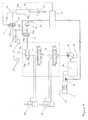
- Fig. 3 is a circuit diagram showing the configuration of a second embodiment of the present invention.
- the open position setting section includes a pressure sensor 21 that detects the pilot pressure oil that has passed through the lock valve 17, and the controller 18 that controls the control valve 15 to keep the close position 15a in accordance with the detection of the pressure of the pilot pressure oil by the pressure sensor 21.
- the controller 18 controls the control valve 15 to keep the close position 15a that is the lower position in the state when no signal is outputted from the detecting section 12, and the controller 18 controls the control valve 15 to switch to the open position 15b that is the upper position in the state when a signal is outputted from the detecting section 12.
- the controller 18 controls the control valve 15 to keep the close position 15a that is the lower position, irrespective of whether or not a signal has been outputted from the detecting section 12.
- the second embodiment is configured in the same manner as the first embodiment.
- the pressure of the pilot pressure oil having passed through the lock valve 17 is not detected by the pressure sensor 21.
- actuation of the actuator 4a is disabled as in the first embodiment.
- the controller 18 controls the control valve 15 to switch from the close position 15a to the open position 15b.
- the pilot pressure oil from the pilot pump 16 is applied to the control part on the right side of the open/close valve 13 via the control valve 15, and the open/close valve 13 is switched from the open position 13a that is the neutral position to the close position 13b. Then, the flow of pressure oil to the tank 25 is blocked, and the load on the hydraulic pump 8 rises. Accordingly, the output of the engine 5a is raised, and the specific process that raises exhaust temperature is carried out in the exhaust gas treatment section 11.
- the lock valve 17 is unlocked in advance, in other words, the lock valve 17 is switched by operation of the lock lever 17a from the lock position 17c to the unlock position 17b, and pilot pressure oil is supplied from the pilot pump 16 to the operating device 19 via the lock valve 17.
- pilot pressure oil supplied with operation of the operating lever 19a of the operating device 19 is applied to the control part of the directional control valve 14, causing the directional control valve 14 to switch from the neutral position.
- the pressure sensor 21 detects the pressure of the pilot pressure oil that has passed through the lock valve 17 and is supplied to the operating device 19, and outputs the corresponding detection signal to the controller 18.
- the controller 18 that has received this signal controls the control valve 15 to keep the close position 15a, irrespective of whether or not a signal indicating the start of the specific process that raises the exhaust temperature of the exhaust gas treatment section 11 has been received from the detecting section 12.
- pilot pressure oil is not supplied from the pilot pump 16 to the control part on the right side of the open/close valve 13, thereby avoiding a situation where the open/close valve 13 is switched from the open position 13a to the close position 13b during actuation of the actuator 4a.
- the process of setting the open/close valve 13 to the open position 13a can be performed by the controller 18 in accordance with the detection signal of the pressure of the pilot pressure oil having passed through the lock valve 17 which is obtained from the pressure sensor 21, without direct regard to the movement of the operating lever 19a of the operating device 19. Accordingly, it is possible to prevent an excessive amount of pressure oil from being supplied from the hydraulic pump 8 to the actuator 4a due to the above-mentioned specific process during switching operation of the directional control valve 14, thereby enhancing reliability in operation of the operating lever 19a of the operating device 19.
- Fig. 4 is a circuit diagram showing the configuration of a third embodiment of the present invention.
- the open position setting section includes a pressure sensor 23 that detects the pressure of the pilot pressure oil supplied with operation of the operating lever 19a of the operating device 19, and the controller 18 that controls the control valve 15 to the close position 15a in accordance with the detection of the pressure of the pilot pressure oil by the pressure sensor 23.
- the exhaust gas treatment apparatus includes: a pipe 32a that connects between the operating device 19 and the directional control valve 14, and introduces pilot pressure oil for setting the directional control valve 14 to the left position; a pipe 32b that connects between the operating device 19 and the directional control valve 14, and introduces pilot pressure oil for setting the directional control valve 14 to the right position; and a shuttle valve 22 that is installed between the pipes 32a and 32b, and detects the higher one of the pressures of pilot pressure oil flowing through the pipes 32a and 32b.
- the above-described pressure sensor 23 detects the pressure of pilot pressure oil selected by the shuttle valve 22, and outputs the corresponding detection signal to the controller 18.
- the third embodiment is configured in the same manner as the second embodiment.
- the controller 18 controls the control valve 15 to switch from the close position 15a to the open position 15b.
- the pilot pressure oil from the pilot pump 16 is applied to the control part on the right side of the open/close valve 13 via the control valve 15, and the open/close valve 13 is switched from the open position 13a that is the neutral position to the close position 13b. Then, the flow of pressure oil to the tank 25 is blocked, and the load on the hydraulic pump 8 rises. Accordingly, the output of the engine 5a is raised, and the specific process that raises exhaust temperature is carried out in the exhaust gas treatment section 11.
- the lock valve 17 is unlocked in advance, in other words, the lock valve 17 is switched by operation of the lock lever 17a from the lock position 17c to the unlock position 17b, and pilot pressure oil is supplied from the pilot pump 16 to the operating device 19 via the lock valve 17. Accordingly, as the operating lever 19a of the operating device 19 is operated, pilot pressure oil is applied to the control part of the directional control valve 14 via one of the pipes 32a and 32b, causing the directional control valve 14 to switch from the neutral position.
- the pressure sensor 23 detects the pressure of pilot pressure oil supplied with the operation of the operating lever 19a of the operating device 19, in other words, the pressure sensor 23 connected to the shuttle valve 22 detects the higher one of the pressures of pilot pressure oil flowing through the pipes 32a and 32b, and outputs the corresponding detection signal to the controller 18.
- the controller 18 that has received this signal controls the control valve 15 to keep the close position 15a.
- pilot pressure oil is not supplied from the pilot pump 16 to the control part on the right side of the open/close valve 13, thereby avoiding a situation where the open/close valve 13 is switched from the open position 13a to the close position 13b during actuation of the actuator 4a.
- the process of setting the open/close valve 13 to the open position 13a can be performed by the controller 18 in accordance with the detection signal of the pressure of pilot pressure oil supplied with the operation of the operating lever 19a of the operating device 19 which is obtained from the pressure sensor 23, without direct regard to the movement of the operating lever 19a of the operating device 19. Accordingly, as in the second embodiment, it is possible to prevent an excessive amount of pressure oil from being supplied from the hydraulic pump 8 to the actuator 4a due to the above-mentioned specific process during switching operation of the directional control valve 14, thereby enhancing reliability in operation of the operating lever 19a of the operating device 19.
- the present invention is not limited to this.
- the present invention is also applicable to regeneration control of a diesel particulate filter (DPF) that captures and removes particulate matter (PM) in exhaust gas.
- DPF diesel particulate filter
Abstract
Description
- This invention relates to an exhaust gas treatment apparatus for a working machine such as a hydraulic excavator which enables a specific process in an exhaust gas treatment section to be carried out, by raising the output of an engine by increasing the hydraulic load on the working machine that is hydraulically driven.
-
Fig. 5 is a circuit diagram showing an example of an exhaust gas treatment apparatus for a working machine according to the related art. - In the related art, working machines such as a hydraulic excavator are provided with an exhaust gas treatment apparatus that treats exhaust gas emitted from an engine and then emits the treated exhaust gas to the outside. As shown in
Fig. 5 , for example, this exhaust gas treatment apparatus includes ahydraulic pump 8 driven by anengine 5a, anactuator 4a that is actuated upon supply of pressure oil from thehydraulic pump 8, adirectional control valve 14 that controls the flow of pressure oil supplied to theactuator 4a, and anoperating device 19 having anoperating lever 19a operated to switch thedirectional control valve 14. - The exhaust gas treatment apparatus also includes a
pilot pump 16 that supplies pressure oil to theoperating device 19, an open/close valve 13 that is arranged downstream of thedirectional control valve 14, and controls the opening and closing of a channel connected to atank 25, acontrol valve 15 that is arranged between the open/close valve 13 and thepilot pump 16, and controls the open/close valve 13 to anopen position 13a or aclose position 13b, and alock valve 17 that is arranged between thepilot pump 16 and theoperating device 19, and can be switched between a lock position 17c for keeping actuation of theactuator 4a disabled, and anunlock position 17b for enabling actuation of theactuator 4a. It should be noted that thehydraulic pump 8, thepilot pump 16, and thelock valve 17 are each connected to thetank 25. Arelief valve 20 is provided in apipe 26 connecting between thepilot pump 16 and thelock valve 17. When the pilot pressure oil supplied from thepilot pump 16 becomes excessive, therelief valve 20 relieves the excess pilot pressure oil to thetank 25. - Further, the exhaust gas treatment apparatus includes an exhaust
gas treatment section 11 that is attached to theexhaust port 10 of theengine 5a, and treats exhaust gas emitted from theengine 5a, a detectingsection 12 that detects when a specific process that raises the exhaust temperature of the exhaustgas treatment section 11 becomes necessary, and outputs a signal for setting thecontrol valve 15 to anopen position 15b, and acontroller 18 that controls thecontrol valve 15. - Specifically, the exhaust
gas treatment section 11 has in the inside a filter (not shown) with an oxidation catalyst such as platinum. By capturing and oxidizing unburned matter such as carbon hydride or carbon monoxide in exhaust gas with the filter, the exhaustgas treatment section 11 changes the unburned matter into harmless matter such as water or carbon dioxide and then emits the harmless matter. At this time, the oxidation catalyst such as platinum provided in the filter does not exert an effective catalytic effect unless its temperature becomes equal to or higher than a predetermined temperature specific to the oxidation catalyst. Accordingly, if the temperature of exhaust gas flowing into the exhaustgas treatment section 11 is lower than this specific predetermined temperature, the captured unburned matter builds up on the filter without being oxidized. As a result, the emission efficiency of exhaust gas in the exhaustgas treatment section 11 deteriorates, resulting in increased exhaust resistance for theengine 5a. To prevent this, in the related art, it is common to perform a specific process that raises the exhaust temperature of the exhaustgas treatment section 11 by raising the temperature of exhaust gas emitted from theengine 5a. The detectingsection 12 includes an exhaust pressure sensor that detects the pressure of exhaust gas flowing into the exhaustgas treatment section 11, and also a temperature sensor that detects the temperature of exhaust gas. When the detectingsection 12 detects by the exhaust pressure sensor that the pressure on the upstream side of the oxidation catalyst has become high, and also exhaust temperature is low, the detectingsection 12 outputs a signal indicating the start of the above-mentioned specific process. - As an example of an exhaust gas treatment apparatus for a working machine which performs such a specific process, there exists a hydraulic working machine in which the detecting
section 12 is provided on the inlet side of an exhaust gas control device provided in a connected fashion to theexhaust port 10 of theengine 5a, in other words, the exhaustgas treatment section 11, and detects the exhaust resistance of theengine 5a, and further, in which thecontroller 18 includes the function of raising the discharge rate and discharge pressure of pressure oil discharged from thehydraulic pump 8, in other words, raising the output of theengine 5a when the exhaust resistance measured by the detectingsection 12 becomes a predetermined preset value or more, thereby raising the temperature of exhaust gas from theengine 5a to a sufficient temperature for enabling the exhaustgas treatment section 11 to exert its exhaust gas treatment capability properly (see, for example, Japanese Patent No.3073380 - As shown in
Fig. 5 , in the hydraulic working machine disclosed in Japanese Patent No.3073380 operating lever 19a of theoperating device 19 is attached with aneutral detection switch 19b for detecting the neutral state of thedirectional control valve 14. The neutral state of thedirectional control valve 14 is electrically detected by closing of the circuit of theneutral detection switch 19b, and the above-mentioned specific process is performed only when thedirectional control valve 14 is in the neutral state, thereby preventing theactuator 4a from operating in a manner not intended by the operator. - In other words, as shown in
Fig. 5 , when thecontroller 18 receives a signal indicating the neutral state of thedirectional control valve 14 on the basis of theneutral detection switch 19b, and the exhaust resistance measured by the detectingsection 12 becomes equal to or higher than a predetermined preset value, thecontroller 18 switches thecontrol valve 15 to theopen position 15b that is the upper position, thereby causing the pilot pressure oil from thepilot pump 16 to be supplied to a control part on the right side of the open/close valve 13 via thecontrol valve 15. Thus, the open/close valve 13 is switched to theclose position 13b that is the right position. Then, the pipe line leading to thetank 25 is closed, and the discharge pressure of the pressure oil discharged from thehydraulic pump 8 rises simultaneously. This prevents an increased amount of pressure oil being supplied from thehydraulic pump 8 to theactuator 4a due to the specific process while the operator is operating theoperating lever 19a of theoperating device 19. In other words, operation of theactuator 4a in a manner not intended by the operator is prevented, thus allowing work to be done safely. - However, in the case of the hydraulic working machine disclosed in Japanese Patent No.
3073380 neutral detection switch 19b that directly detects the movement of theoperating lever 19a of theoperating device 19, for example, in the event of a malfunction such that the circuit of theneutral detection switch 19b closes even through thedirectional control valve 14 is being switched with theoperating lever 19a of theoperating device 19, a signal indicating the neutral state of thedirectional control valve 14 is outputted to thecontroller 18 from theneutral detection switch 19b. In this case, thecontroller 18 performs the above-mentioned specific process in which when the exhaust resistance measured by the detectingsection 12 becomes a predetermined preset value or more, thecontrol valve 15 is switched to theopen position 15b that is the upper position to thereby cause the pilot pressure oil from thepilot pump 16 to be supplied to the control part on the right side of the open/close valve 13 via thecontrol valve 15, and the open/close valve 13 is switched to theclose position 13b that is the right position to thereby raise the discharge pressure of the pressure oil discharged from thehydraulic pump 8 simultaneously. Consequently, excess pressure oil is supplied to theactuator 4a while thedirectional control valve 14 is being switched with theoperating lever 19a of theoperating device 19, so the speed of theactuator 4a increases,
resulting in an operation not intended by the operator. - The present invention has been made in view of the above circumstances of the related art and provides an exhaust gas treatment apparatus for a working machine which can reliably prevent a specific process that raises the exhaust temperature of the exhaust gas treatment section from being carried out during switching operation of the directional control valve.
- To this end, according to an embodiment of the present invention, there is provided an exhaust gas treatment apparatus for a working machine, including: a hydraulic pump driven by an engine; an actuator that is actuated upon supply of pressure oil from the hydraulic pump; a directional control valve that controls a flow of the pressure oil supplied to the actuator; an operating device having an operating lever operated to switch the directional control valve; a pilot pump that supplies pressure oil to the operating device; an open/close valve that is arranged downstream of the directional control valve and connected to a tank, and whose neutral position is an open position; a control valve that is arranged between the open/close valve and the pilot pump, and controls the open/close valve to the open position or a close position; a lock valve that is arranged between the pilot pump and the operating device, and can be switched to a lock position for keeping actuation of the actuator disabled; an exhaust gas treatment section that treats exhaust gas emitted from the engine; a detecting section that detects when a specific process that raises an exhaust temperature of the exhaust gas treatment section is necessary, and outputs a signal for setting the control valve to an open position; a controller that controls the control valve; and an open position setting section that performs a process of setting the open/close valve to the open position in accordance with pilot pressure oil supplied from the pilot pump, in which the specific process in the exhaust gas treatment section can be carried out by keeping the open/close valve in the close position and raising an output of the engine.
- In the embodiment of the present invention configured as described above, when the lock valve is kept in the lock position, pilot pressure oil is not supplied to the operating device, and accordingly the process of setting the open/close valve to the open position is not performed by the open position setting section. Also, in the state with the lock valve kept in the lock position in this way to disable actuation of the actuator, when the detecting section outputs a signal indicating that it is necessary to start the specific process that raises the exhaust temperature of the exhaust gas treatment section, the control valve is switched to the open position. Thus, the pilot pressure oil from the pilot pump is applied to the control part of the open/close valve via the control valve, and the open/close valve is switched from the open position that is the neutral position to the close position. Then, the flow of pressure oil to the tank is blocked, and the load on the hydraulic pump rises. Accordingly, the output of the engine is raised, and the specific process that raises exhaust temperature is carried out in the exhaust gas treatment section.
- On the other hand, to actuate the actuator, the lock valve is unlocked in advance, and pilot pressure oil is supplied from the pilot pump to the operating device via the lock valve. Then, the pilot pressure oil supplied with operation of the operating lever of the operating device is applied to the control part of the directional control valve, causing the directional control valve to switch from the neutral position. Accordingly, the pressure oil discharged from the hydraulic pump is supplied to the actuator via the directional control valve, thereby actuating the actuator.
- Therefore, in the state with the lock valve unlocked in this way to enable operation of the operating lever of the operating device, the process of setting the open/close valve to the open position can be performed by the open position setting section in accordance with the pilot pressure oil supplied from the pilot pump, without direct regard to the movement of the operating lever of the operating device. Thus, even when a signal indicating that it is necessary to start the specific process that raises the exhaust temperature of the exhaust gas treatment section is outputted by the detecting section, the load on the hydraulic pump is prevented from increasingly excessively, thus avoiding a situation where, following such an increase in load, the above-described specific process that raises exhaust temperature by raising the output of the engine is started. This makes it possible to reliably prevent the specific process that raises the exhaust temperature of the exhaust gas treatment section from being carried out during switching operation of the directional control valve.
- According to an embodiment of the present invention, in the exhaust gas treatment apparatus for a working machine according to the above embodiment of the present invention, the open position setting section includes the pilot pump, the lock valve that is kept in an unlock position for supplying the pilot pressure oil from the pilot pump to the operating device, and a pipe that has one end connected in between the lock valve and the operating device, and introduces the pilot pressure oil for setting the open/close valve to the open position.
- In the embodiment of the present invention configured as described above, in the state with the lock valve unlocked in this way to enable actuation of the actuator by operation of the operating lever of the operating device, the pilot pressure oil from the pilot pump is introduced to the control part of the open/close valve by the pipe included in the open position setting section whose one end is connected in between the lock valve and the operating device. Thus, the open/close valve is kept in the open position that is the neural position, thereby making it possible to prevent the specific process that raises the exhaust temperature of the exhaust gas treatment section from being carried out during switching operation of the directional control valve, solely by the simple configuration of simply providing the pipe.
- According to an embodiment of the present invention, in the exhaust gas treatment apparatus for a working machine according to the above embodiment of the present invention, the open position setting section includes the pilot pump, the lock valve that is kept in an unlock position for supplying the pilot pressure oil from the pilot pump to the operating device, a pressure sensor that detects a pressure of the pilot pressure oil that has passed through the lock valve, and the controller that controls the control valve to keep a close position in accordance with detection of the pressure of the pilot pressure oil by the pressure sensor.
- In the embodiment of the present invention configured as described above, in the state with the lock valve kept in the lock position, the pressure of the pilot pressure oil having passed through the lock valve is not detected by the pressure sensor. In this state, actuation of the actuator is disabled. When, in this state, the detecting section outputs a signal indicating that it is necessary to start the specific process that raises the exhaust temperature of the exhaust gas treatment section, the control valve is switched to the open position. Thus, the pilot pressure oil from the pilot pump is applied to the control part of the open/close valve via the control valve, and the open/close valve is switched from the open position that is the neutral position to the close position. Then, the flow of pressure oil to the tank is blocked, and the load on the hydraulic pump rises. Accordingly, the output of the engine is raised, and the specific process that raises exhaust temperature is carried out in the exhaust gas treatment section.
- On the other hand, to actuate the actuator, the lock valve is unlocked in advance, and pilot pressure oil is supplied from the pilot pump to the operating device via the lock valve. Following this, the pilot pressure oil supplied with operation of the operating lever of the operating device is applied to the control part of the directional control valve, causing the directional control valve to switch from the neutral position. At this time, in the open position setting section, the pressure sensor detects the pressure of the pilot pressure oil that has passed through the lock valve and is supplied to the operating device, and outputs the corresponding detection signal to the controller. The controller that has received this signal controls the control valve to keep the close position. Hence, pilot pressure oil is not supplied from the pilot pump to the control part of the open/close valve, thereby avoiding a situation where the open/close valve is switched from the open position to the close position during actuation of the actuator. Therefore, in the open position setting section, the process of setting the open/close valve to the open position can be performed by the controller in accordance with the detection signal of the pressure of the pilot pressure oil having passed through the lock valve which is obtained from the pressure sensor, without direct regard to the movement of the operating lever of the operating device. Accordingly, it is possible to prevent an excessive amount of pressure oil from being supplied from the pilot pump to the actuator due to the above-mentioned specific process during switching operation of the directional control valve, thereby enhancing reliability in operation of the operating lever of the operating device.
- According to an embodiment of the present invention, in the exhaust gas treatment apparatus for a working machine according to the above embodiment of the present invention, the open position setting section includes the pilot pump, the lock valve that is kept in an unlock position for supplying the pilot pressure oil from the pilot pump to the operating device, a pressure sensor that detects a pressure of the pilot pressure oil supplied with operation of the operating lever of the operating device, and the controller that controls the control valve to keep a close position in accordance with detection of the pressure of the pilot pressure oil by the pressure sensor.
- In the embodiment of the present invention configured as described above, in the state with the lock valve kept in the lock position, the pressure of the pilot pressure oil supplied with operation of the operating lever of the operating device is not detected by the pressure sensor. In this state, actuation of the actuator is disabled. When, in this state, the detecting section outputs a signal indicating that it is necessary to start the specific process that raises the exhaust temperature of the exhaust gas treatment section, the control valve is switched to the open position. Thus, the pilot pressure oil from the pilot pump is applied to the control part of the open/close valve via the control valve, and the open/close valve is switched from the open position that is the neutral position to the close position. Then, the flow of pressure oil to the tank is blocked, and the load on the hydraulic pump rises. Accordingly, the output of the engine is raised, and the specific process that raises exhaust temperature is carried out in the exhaust gas treatment section.
- On the other hand, to actuate the actuator, the lock valve is unlocked in advance, and pilot pressure oil is supplied from the pilot pump to the operating device via the lock valve. Following this, the pilot pressure oil supplied with operation of the operating lever of the operating device is applied to the control part of the directional control valve, causing the directional control valve to switch from the neutral position. At this time, in the open position setting section, the pressure sensor detects the pressure of the pilot pressure oil supplied with the operation of the operating device, and outputs the corresponding detection signal to the controller. The controller that has received this signal controls the control valve to keep the close position. Hence, pilot pressure oil is not supplied from the pilot pump to the control part of the open/close valve, thereby avoiding a situation where the open/close valve is switched from the open position to the close position during actuation of the actuator. In this way, in the open position setting section, the process of setting the open/close valve to the open position can be performed by the controller in accordance with the detection signal of the pressure of the pilot pressure oil supplied with the operation of the operating lever of the operating device which is obtained from the pressure sensor, without direct regard to the movement of the operating lever of the operating device. Accordingly, it is possible to prevent an excessive amount of pressure oil from being supplied from the pilot pump to the actuator due to the above-mentioned specific process during switching operation of the directional control valve, thereby enhancing reliability in operation of the operating lever of the operating device.
- An exhaust gas treatment apparatus for a working machine according to an embodiment of the present invention enables a specific process in the exhaust gas treatment section to be carried out, by keeping the open/close valve in the close position and raising the output of the engine, and includes an open position setting section that performs a process of setting the open/close valve to the open position in accordance with the pilot pressure oil supplied from the pilot pump. Therefore, in the state with the lock valve unlocked in advance to enable operation of the operating lever of the operating device, the process of setting the open/close valve to the open position can be performed by the open position setting section in accordance with the pilot pressure oil supplied from the pilot pump via the lock valve, without direct regard to the movement of the operating lever of the operating device. Thus, even when a signal indicating that it is necessary to start the above-mentioned specific process is outputted by the detecting section, the flow of pressure oil to the tank is not blocked, thereby preventing the load on the hydraulic pump from rising excessively. This makes it possible to reliably prevent the specific process that raises the exhaust temperature of the exhaust gas treatment section by raising the output of the engine from being carried out during switching operation of the directional control valve. Further, since an excessive amount of pressure oil is not supplied to the actuator, operation of the actuator in a manner not intended by the operator is prevented, thereby improving safety in operating the working machine over the related art.
- Embodiments of the present invention will be described in detail based on the following drawings, wherein:
-
Fig. 1 is a side view showing a hydraulic excavator illustrated as an example of a working machine equipped with an exhaust gas treatment apparatus for a working machine according to a first embodiment of the present invention; -
Fig. 2 is a circuit diagram showing the configuration of the first embodiment of the present invention; -
Fig. 3 is a circuit diagram showing the configuration of a second embodiment of the present invention; -
Fig. 4 is a circuit diagram showing the configuration of a third embodiment of the present invention; and -
Fig. 5 is a circuit diagram showing an example of an exhaust gas treatment apparatus for a working machine according to the related art. - Hereinbelow, modes for implementing an exhaust gas treatment apparatus for a working machine according to the present invention will be described with reference to the drawings.
- An exhaust gas treatment apparatus for a working machine according to a first embodiment of the present invention is provided in, for example, a
hydraulic excavator 1 as shown inFig. 1 . Thehydraulic excavator 1 has a travellingbody 2, aswing body 3 arranged above the travellingbody 2 and having a swing frame 3a, and afront attachment 4 that is attached to the front of theswing body 3 and rotates in the vertical direction. Thefront attachment 4 includesactuators 4a, 4b, and 4c for controlling a boom, an arm, and a bucket, respectively. Also, theswing body 3 includes acab 7 located at the front, a counterweight 6 arranged at the rear, and an engine room 5 that is arranged between thecab 7 and the counterweight 6, and has anengine 5a described later inside. - As shown in
Fig. 2 , the exhaust gas treatment apparatus according to the first embodiment of the present invention includes ahydraulic pump 8 that is driven by theengine 5a arranged inside the engine room 5, the above-describedactuator 4a that is actuated upon supply of pressure oil from thehydraulic pump 8, adirectional control valve 14 that controls the flow of pressure oil supplied to theactuator 4a, and an operatingdevice 19 having an operatinglever 19a operated to switch thedirectional control valve 14. It should be noted that for the simplicity of description, of theactuators 4a, 4b, and 4c, only theactuator 4a is illustrated, and the other actuators 4b and 4c are not shown. - Also, the exhaust gas treatment apparatus according to the first embodiment of the present invention includes: a
pilot pump 16 that supplies pressure oil to the operatingdevice 19; an open/close valve 13 that is arranged downstream of thedirectional control valve 14 and is connected to atank 25, and whose neutral position is set to anopen position 13a by aspring 13c, for example; acontrol valve 15 that is arranged between the open/close valve 13 and thepilot pump 16, and controls the open/close valve 13 to theopen position 13a or aclose position 13b; and alock valve 17 that is arranged between thepilot pump 16 and the operatingdevice 19, and can be switched by operation of alock lever 17a between a lock position 17c for keeping actuation of theactuator 4a disabled, and anunlock position 17b for enabling actuation of theactuator 4a. It should be noted that thehydraulic pump 8, thepilot pump 16, and thelock valve 17 are connected to thetank 25. Arelief valve 20 is provided in apipe 26 connecting between thepilot pump 16 and thelock valve 17. When the pilot pressure oil supplied from thepilot pump 16 becomes excessive, therelief valve 20 relieves the excess pilot pressure oil to thetank 25. - Further, the exhaust gas treatment apparatus according to the first embodiment of the present invention includes: an exhaust
gas treatment section 11 that treats exhaust gas emitted from theengine 5a; a detectingsection 12 that detects when a specific process that raises the exhaust temperature of the exhaustgas treatment section 11 becomes necessary, and outputs a signal for switching thecontrol valve 15 to the open position; and acontroller 18 that controls thecontrol valve 15. The specific process in the exhaustgas treatment section 11 can be carried out by keeping the open/close valve 13 in theclose position 13b and raising the output of theengine 5a. - Further, the exhaust gas treatment apparatus according to the first embodiment of the present invention includes an open position setting section that performs a process of setting the opening/
close valve 13 to theopen position 13a in accordance with the pilot pressure oil supplied from thepilot pump 16. This open position setting section includes: thepilot pump 16; thelock valve 17 that is kept in theunlock position 17b for supplying pilot pressure oil from thepilot pump 16 to the operatingdevice 19; and apipe 31 whose one end is connected in between thelock valve 17 and the operatingdevice 19, and whose other end is connected to a control part on the left side of the open/close valve 13 so that the open/close valve 13 is set to theopen position 13a by introducing the pilot pressure oil flowing between thelock valve 17 and the operatingdevice 19. It should be noted that in the first embodiment of the present invention, portions corresponding to those of the exhaust gas treatment apparatus for a working machine according to the related art shown inFig. 5 described above are denoted by the same symbols. - In the first embodiment of the present invention configured in this way, when the
lock valve 17 is kept in the lock position 17c, pilot pressure oil is not supplied to the operatingdevice 19, and thus pilot pressure oil is not introduced from thepipe 31 in the open position setting section. At this time, the opening/close valve 13 is kept in theopen position 13a that is the neutral position with the force of thespring 13c. Also, in the state with thelock valve 17 kept in the lock position 17c in this way to disable actuation of theactuator 4a, when the detectingsection 12 outputs a signal indicating that it is necessary to start a specific process that raises the exhaust temperature of the exhaustgas treatment section 11, thecontrol valve 15 is switched to theopen position 15b that is the upper position by a signal outputted from thecontroller 18. Thus, the pilot pressure oil from thepilot pump 16 is applied to a control part on the right side of the open/close valve 13 via thecontrol valve 15, and the open/close valve 13 is switched from theopen position 13a that is the neutral position to theclose position 13b, against the force of thespring 13c. Then, the flow of pressure oil to thetank 25 is blocked, and the load on thehydraulic pump 8 rises. Accordingly, the output of theengine 5a is raised, and the specific process that raises exhaust temperature is carried out in the exhaustgas treatment section 11. - On the other hand, to actuate the
actuator 4a, thelock valve 17 is unlocked in advance, in other words, thelock valve 17 is switched by operation of thelock lever 17a from the lock position 17c to theunlock position 17b, and pilot pressure oil is supplied from thepilot pump 16 to the operatingdevice 19 via thelock valve 17. Then, the pilot pressure oil supplied with operation of the operatinglever 19a of the operatingdevice 19 is applied to the control part of thedirectional control valve 14, causing thedirectional control valve 14 to switch from the neutral position.
Accordingly, the pressure oil discharged from thehydraulic pump 8 is supplied to theactuator 4a via thedirectional control valve 14, thereby actuating theactuator 4a. - Therefore, in the state with the
lock valve 17 unlocked in this way to enable operation of the operatinglever 19a of the operatingdevice 19, by introducing pilot pressure oil to the control part on the left side of the open/close valve 13 from thepipe 31 whose one end is connected in between thelock valve 17 and the operatingdevice 19, the process of setting the open/close valve 13 to theopen position 13a can be performed in accordance with the pilot pressure oil supplied from thepilot pump 16, without direct regard to the movement of the operatinglever 19a of the operatingdevice 19. In this state, when thecontroller 18 receives, from the detectingsection 12, a signal indicating the start of the specific process that raises the exhaust temperature of the exhaustgas treatment section 11, and accordingly controls thecontrol valve 15 to switch from theclose position 15a to theopen position 15b, pilot pressure oil from thepilot pump 16 is supplied to the control part on the right side of the open/close valve 13 via thecontrol valve 15. At this time, the same pilot pressure oil from thepilot pump 16 is introduced to the control parts on the left and right of the open/close valve 13. Therefore, the open/close valve 13 is kept in the neutral position with the force of thespring 13c. This prevents the load on thehydraulic pump 8 from increasingly excessively, thus avoiding a situation where, following such an increase in load, the above-described specific process that raises exhaust temperature by raising the output of theengine 5a is started. This makes it possible to reliably prevent the specific process that raises the exhaust temperature of the exhaustgas treatment section 11 from being carried out during switching operation of thedirectional control valve 14. Since an excessive amount of pressure oil is not supplied to theactuator 4a, operation of theactuator 4a in a manner not intended by the operator is prevented, thereby improving safety in operating thehydraulic excavator 1. - Also, in the first embodiment of the present invention, one end of the
pipe 31 included in the open position setting section is connected in between thelock valve 17 and the operatingdevice 19, and the other end of thepipe 31 is connected to the control part on the left side of the open/close valve 13 so that the open/close valve 13 is set to theopen position 13a by introducing the pilot pressure oil flowing between thelock valve 17 and the operatingdevice 19. In the state when thelock valve 17 is in theunlock position 17b, in other words, when actuation of theactuator 4a is enabled, the open/close valve 13 can be kept in theopen position 13a solely by such a simple configuration. Therefore, since it suffices to simply provide thepipe 31 that connects to the control part of the open/close valve 13 from in between thelock valve 17 and the operatingdevice 19, assembly cost for the open position setting section can be minimized. -
Fig. 3 is a circuit diagram showing the configuration of a second embodiment of the present invention. - As shown in
Fig. 3 , in the second embodiment of the present invention, the open position setting section includes apressure sensor 21 that detects the pilot pressure oil that has passed through thelock valve 17, and thecontroller 18 that controls thecontrol valve 15 to keep theclose position 15a in accordance with the detection of the pressure of the pilot pressure oil by thepressure sensor 21. When pilot pressure oil is not detected by thepressure sensor 21, thecontroller 18 controls thecontrol valve 15 to keep theclose position 15a that is the lower position in the state when no signal is outputted from the detectingsection 12, and thecontroller 18 controls thecontrol valve 15 to switch to theopen position 15b that is the upper position in the state when a signal is outputted from the detectingsection 12. Also, when pilot pressure oil is detected by thepressure sensor 21, thecontroller 18 controls thecontrol valve 15 to keep theclose position 15a that is the lower position, irrespective of whether or not a signal has been outputted from the detectingsection 12. Otherwise, the second embodiment is configured in the same manner as the first embodiment. - In the second embodiment of the present invention configured in this way, in the state with the
lock valve 17 kept in the lock position 17c, the pressure of the pilot pressure oil having passed through thelock valve 17 is not detected by thepressure sensor 21. In this state, actuation of theactuator 4a is disabled as in the first embodiment. When, in this state, a signal indicating that it is necessary to start a specific process that raises the exhaust temperature of the exhaustgas treatment section 11 is outputted by the detectingsection 12, since the pressure of pilot pressure oil has not been detected by thepressure sensor 21, thecontroller 18 controls thecontrol valve 15 to switch from theclose position 15a to theopen position 15b. Thus, the pilot pressure oil from thepilot pump 16 is applied to the control part on the right side of the open/close valve 13 via thecontrol valve 15, and the open/close valve 13 is switched from theopen position 13a that is the neutral position to theclose position 13b. Then, the flow of pressure oil to thetank 25 is blocked, and the load on thehydraulic pump 8 rises. Accordingly, the output of theengine 5a is raised, and the specific process that raises exhaust temperature is carried out in the exhaustgas treatment section 11. - On the other hand, to actuate the
actuator 4a, thelock valve 17 is unlocked in advance, in other words, thelock valve 17 is switched by operation of thelock lever 17a from the lock position 17c to theunlock position 17b, and pilot pressure oil is supplied from thepilot pump 16 to the operatingdevice 19 via thelock valve 17. Following this, pilot pressure oil supplied with operation of the operatinglever 19a of the operatingdevice 19 is applied to the control part of thedirectional control valve 14, causing thedirectional control valve 14 to switch from the neutral position. At this time, in the open position setting section, thepressure sensor 21 detects the pressure of the pilot pressure oil that has passed through thelock valve 17 and is supplied to the operatingdevice 19, and outputs the corresponding detection signal to thecontroller 18. Thecontroller 18 that has received this signal controls thecontrol valve 15 to keep theclose position 15a, irrespective of whether or not a signal indicating the start of the specific process that raises the exhaust temperature of the exhaustgas treatment section 11 has been received from the detectingsection 12. Hence, pilot pressure oil is not supplied from thepilot pump 16 to the control part on the right side of the open/close valve 13, thereby avoiding a situation where the open/close valve 13 is switched from theopen position 13a to theclose position 13b during actuation of theactuator 4a. Therefore, in the open position setting section, the process of setting the open/close valve 13 to theopen position 13a can be performed by thecontroller 18 in accordance with the detection signal of the pressure of the pilot pressure oil having passed through thelock valve 17 which is obtained from thepressure sensor 21, without direct regard to the movement of the operatinglever 19a of the operatingdevice 19. Accordingly, it is possible to prevent an excessive amount of pressure oil from being supplied from thehydraulic pump 8 to theactuator 4a due to the above-mentioned specific process during switching operation of thedirectional control valve 14, thereby enhancing reliability in operation of the operatinglever 19a of the operatingdevice 19. -
Fig. 4 is a circuit diagram showing the configuration of a third embodiment of the present invention. - As shown in
Fig. 4 , in the third embodiment of the present invention, the open position setting section includes apressure sensor 23 that detects the pressure of the pilot pressure oil supplied with operation of the operatinglever 19a of the operatingdevice 19, and thecontroller 18 that controls thecontrol valve 15 to theclose position 15a in accordance with the detection of the pressure of the pilot pressure oil by thepressure sensor 23. Specifically, the exhaust gas treatment apparatus according to the third embodiment of the present invention includes: apipe 32a that connects between the operatingdevice 19 and thedirectional control valve 14, and introduces pilot pressure oil for setting thedirectional control valve 14 to the left position; apipe 32b that connects between the operatingdevice 19 and thedirectional control valve 14, and introduces pilot pressure oil for setting thedirectional control valve 14 to the right position; and a shuttle valve 22 that is installed between thepipes pipes pressure sensor 23 detects the pressure of pilot pressure oil selected by the shuttle valve 22, and outputs the corresponding detection signal to thecontroller 18. Otherwise, the third embodiment is configured in the same manner as the second embodiment. - In the third embodiment of the present invention configured in this way, in the state with the
lock valve 17 kept in the lock position 17c, the pressure of the pilot pressure oil supplied with operation of the operatinglever 19a of the operatingdevice 19 is not detected by thepressure sensor 23 connected to the shuttle valve 22. In this state, actuation of theactuator 4a is disabled in this state. When, in this state, a signal indicating that it is necessary to start a specific process that raises the exhaust temperature of the exhaustgas treatment section 11 is outputted by the detectingsection 12, since a detection signal of the pressure of pilot pressure oil has not been outputted from thepressure sensor 23, thecontroller 18 controls thecontrol valve 15 to switch from theclose position 15a to theopen position 15b. Thus, the pilot pressure oil from thepilot pump 16 is applied to the control part on the right side of the open/close valve 13 via thecontrol valve 15, and the open/close valve 13 is switched from theopen position 13a that is the neutral position to theclose position 13b. Then, the flow of pressure oil to thetank 25 is blocked, and the load on thehydraulic pump 8 rises. Accordingly, the output of theengine 5a is raised, and the specific process that raises exhaust temperature is carried out in the exhaustgas treatment section 11. - On the other hand, to actuate the
actuator 4a, thelock valve 17 is unlocked in advance, in other words, thelock valve 17 is switched by operation of thelock lever 17a from the lock position 17c to theunlock position 17b, and pilot pressure oil is supplied from thepilot pump 16 to the operatingdevice 19 via thelock valve 17. Accordingly, as the operatinglever 19a of the operatingdevice 19 is operated, pilot pressure oil is applied to the control part of thedirectional control valve 14 via one of thepipes directional control valve 14 to switch from the neutral position. At this time, in the open position setting section, thepressure sensor 23 detects the pressure of pilot pressure oil supplied with the operation of the operatinglever 19a of the operatingdevice 19, in other words, thepressure sensor 23 connected to the shuttle valve 22 detects the higher one of the pressures of pilot pressure oil flowing through thepipes controller 18. Thecontroller 18 that has received this signal controls thecontrol valve 15 to keep theclose position 15a. Hence, pilot pressure oil is not supplied from thepilot pump 16 to the control part on the right side of the open/close valve 13, thereby avoiding a situation where the open/close valve 13 is switched from theopen position 13a to theclose position 13b during actuation of theactuator 4a. In this way, in the open position setting section, the process of setting the open/close valve 13 to theopen position 13a can be performed by thecontroller 18 in accordance with the detection signal of the pressure of pilot pressure oil supplied with the operation of the operatinglever 19a of the operatingdevice 19 which is obtained from thepressure sensor 23, without direct regard to the movement of the operatinglever 19a of the operatingdevice 19. Accordingly, as in the second embodiment, it is possible to prevent an excessive amount of pressure oil from being supplied from thehydraulic pump 8 to theactuator 4a due to the above-mentioned specific process during switching operation of thedirectional control valve 14, thereby enhancing reliability in operation of the operatinglever 19a of the operatingdevice 19. - While the above embodiments are directed to the case of purifying exhaust gas by use of an oxidation catalyst as an example of an exhaust gas treatment apparatus, the present invention is not limited to this. The present invention is also applicable to regeneration control of a diesel particulate filter (DPF) that captures and removes particulate matter (PM) in exhaust gas.
Claims (4)
- An exhaust gas treatment apparatus for a working machine, comprising:a hydraulic pump driven by an engine;an actuator that is actuated upon supply of pressure oil from the hydraulic pump;a directional control valve that controls a flow of the pressure oil supplied to the actuator;an operating device having an operating lever operated to switch the directional control valve;a pilot pump that supplies pressure oil to the operating device;an open/close valve that is arranged downstream of the directional control valve and connected to a tank, and whose neutral position is an open position;a control valve that is arranged between the open/close valve and the pilot pump, and controls the open/close valve to the open position or a close position;a lock valve that is arranged between the pilot pump and the operating device, and can be switched to a lock position for keeping actuation of the actuator disabled;an exhaust gas treatment section that treats exhaust gas emitted from the engine;a detecting section that detects when a specific process that raises an exhaust temperature of the exhaust gas treatment section is necessary, and outputs a signal for setting the control valve to an open position;a controller that controls the control valve; andan open position setting section that performs a process of setting the open/close valve to the open position in accordance with pilot pressure oil supplied from the pilot pump,wherein the specific process in the exhaust gas treatment section can be carried out by keeping the open/close valve in the close position and raising an output of the engine.
- The exhaust gas treatment apparatus for a working machine according to Claim 1, wherein the open position setting section includes:the pilot pump;the lock valve that is kept in an unlock position for supplying the pilot pressure oil from the pilot pump to the operating device; anda pipe that has one end connected in between the lock valve and the operating device, and introduces the pilot pressure oil for setting the open/close valve to the open position.
- The exhaust gas treatment apparatus for a working machine according to Claim 1, wherein the open position setting section includes:the pilot pump;the lock valve that is kept in an unlock position for supplying the pilot pressure oil from the pilot pump to the operating device;a pressure sensor that detects a pressure of the pilot pressure oil that has passed through the lock valve; andthe controller that controls the control valve to keep a close position in accordance with detection of the pressure of the pilot pressure oil by the pressure sensor.
- The exhaust gas treatment apparatus for a working machine according to Claim 1, wherein the open position setting section includes:the pilot pump;the lock valve that is kept in an unlock position for supplying the pilot pressure oil from the pilot pump to the operating device;a pressure sensor that detects a pressure of the pilot pressure oil supplied with operation of the operating lever of the operating device; and
the controller that controls the control valve to keep a close position in accordance with detection of the pressure of the pilot pressure oil by the pressure sensor.
Applications Claiming Priority (1)
| Application Number | Priority Date | Filing Date | Title |
|---|---|---|---|
| JP2010053467A JP5230674B2 (en) | 2010-03-10 | 2010-03-10 | Exhaust gas treatment equipment for work machines |
Publications (2)
| Publication Number | Publication Date |
|---|---|
| EP2365195A1 true EP2365195A1 (en) | 2011-09-14 |
| EP2365195B1 EP2365195B1 (en) | 2012-11-07 |
Family
ID=44121440
Family Applications (1)
| Application Number | Title | Priority Date | Filing Date |
|---|---|---|---|
| EP11156226A Active EP2365195B1 (en) | 2010-03-10 | 2011-02-28 | Exhaust gas treatment apparatus for working machine |
Country Status (3)
| Country | Link |
|---|---|
| US (1) | US8534052B2 (en) |
| EP (1) | EP2365195B1 (en) |
| JP (1) | JP5230674B2 (en) |
Cited By (2)
| Publication number | Priority date | Publication date | Assignee | Title |
|---|---|---|---|---|
| CN104246086A (en) * | 2012-01-04 | 2014-12-24 | 派克汉尼芬公司 | Hydraulic hybrid swing drive system for excavators |
| CN104736804A (en) * | 2012-10-11 | 2015-06-24 | 株式会社斗山 | Safety device for preventing working-apparatus operation during regeneration of forklift-truck diesel-exhaust-gas after-treatment device |
Families Citing this family (2)
| Publication number | Priority date | Publication date | Assignee | Title |
|---|---|---|---|---|
| KR101958026B1 (en) * | 2012-12-26 | 2019-03-13 | 두산인프라코어 주식회사 | hydraulic circuit system for forced regeneration of Diesel Particulate Filter |
| GB2598352A (en) * | 2020-08-27 | 2022-03-02 | Bamford Excavators Ltd | A control system |
Citations (2)
| Publication number | Priority date | Publication date | Assignee | Title |
|---|---|---|---|---|
| JPH0373380B2 (en) | 1986-04-25 | 1991-11-21 | Eagle Ind Co Ltd | |
| JPH07166840A (en) * | 1993-12-17 | 1995-06-27 | Hitachi Constr Mach Co Ltd | Hydraulic work machine provided with exhaust emission control device |
Family Cites Families (1)
| Publication number | Priority date | Publication date | Assignee | Title |
|---|---|---|---|---|
| EP2208872B1 (en) * | 2007-11-06 | 2017-12-13 | Hitachi Construction Machinery Co., Ltd. | Work vehicle with exhaust purification system |
-
2010
- 2010-03-10 JP JP2010053467A patent/JP5230674B2/en active Active
-
2011
- 2011-02-28 EP EP11156226A patent/EP2365195B1/en active Active
- 2011-03-01 US US13/037,959 patent/US8534052B2/en active Active
Patent Citations (2)
| Publication number | Priority date | Publication date | Assignee | Title |
|---|---|---|---|---|
| JPH0373380B2 (en) | 1986-04-25 | 1991-11-21 | Eagle Ind Co Ltd | |
| JPH07166840A (en) * | 1993-12-17 | 1995-06-27 | Hitachi Constr Mach Co Ltd | Hydraulic work machine provided with exhaust emission control device |
Cited By (4)
| Publication number | Priority date | Publication date | Assignee | Title |
|---|---|---|---|---|
| CN104246086A (en) * | 2012-01-04 | 2014-12-24 | 派克汉尼芬公司 | Hydraulic hybrid swing drive system for excavators |
| CN104246086B (en) * | 2012-01-04 | 2016-08-03 | 派克汉尼芬公司 | The hydraulic hybrid gyroscopic drive system of excavator |
| CN104736804A (en) * | 2012-10-11 | 2015-06-24 | 株式会社斗山 | Safety device for preventing working-apparatus operation during regeneration of forklift-truck diesel-exhaust-gas after-treatment device |
| CN104736804B (en) * | 2012-10-11 | 2017-07-25 | 株式会社斗山 | The safety device that working rig is operated is prevented in the diesel exhaust after-treatment device regeneration of fork truck |
Also Published As
| Publication number | Publication date |
|---|---|
| JP2011184988A (en) | 2011-09-22 |
| JP5230674B2 (en) | 2013-07-10 |
| US20110219744A1 (en) | 2011-09-15 |
| US8534052B2 (en) | 2013-09-17 |
| EP2365195B1 (en) | 2012-11-07 |
Similar Documents
| Publication | Publication Date | Title |
|---|---|---|
| JP5271758B2 (en) | Hydraulic drive device for work machine | |
| US9080481B2 (en) | Construction machine hydraulic drive system having exhaust gas purifying device | |
| US8919109B2 (en) | Hydraulic drive system for construction machine having exhaust gas purification device | |
| EP2354330B1 (en) | Engine controller for the hydraulic circuit of a construction machine | |
| KR101464020B1 (en) | Construction machine | |
| US10273658B2 (en) | Construction machine | |
| EP2423481B1 (en) | Exhaust gas cleaning system for engineering vehicle | |
| US8601799B2 (en) | Construction machine | |
| US8756916B2 (en) | Hydraulic driving device for working machine | |
| EP2365195B1 (en) | Exhaust gas treatment apparatus for working machine | |
| JP2011112004A (en) | Dpf forcible regeneration circuit for construction machine | |
| KR20140047068A (en) | Engine control system for work machine | |
| JP3876220B2 (en) | Automatic booster for work machines | |
| CN105986592B (en) | Shovel and management device for shovel | |
| JP2014206222A (en) | Hydraulic drive device and hydraulic drive method | |
| JP5629449B2 (en) | Handling equipment | |
| US11236654B2 (en) | Construction machine | |
| CN117693635A (en) | Engineering machinery |
Legal Events
| Date | Code | Title | Description |
|---|---|---|---|
| PUAI | Public reference made under article 153(3) epc to a published international application that has entered the european phase |
Free format text: ORIGINAL CODE: 0009012 |
|
| 17P | Request for examination filed |
Effective date: 20110228 |
|
| AK | Designated contracting states |
Kind code of ref document: A1 Designated state(s): AL AT BE BG CH CY CZ DE DK EE ES FI FR GB GR HR HU IE IS IT LI LT LU LV MC MK MT NL NO PL PT RO RS SE SI SK SM TR |
|
| AX | Request for extension of the european patent |
Extension state: BA ME |
|
| GRAC | Information related to communication of intention to grant a patent modified |
Free format text: ORIGINAL CODE: EPIDOSCIGR1 |
|
| GRAP | Despatch of communication of intention to grant a patent |
Free format text: ORIGINAL CODE: EPIDOSNIGR1 |
|
| GRAS | Grant fee paid |
Free format text: ORIGINAL CODE: EPIDOSNIGR3 |
|
| GRAA | (expected) grant |
Free format text: ORIGINAL CODE: 0009210 |
|
| AK | Designated contracting states |
Kind code of ref document: B1 Designated state(s): AL AT BE BG CH CY CZ DE DK EE ES FI FR GB GR HR HU IE IS IT LI LT LU LV MC MK MT NL NO PL PT RO RS SE SI SK SM TR |
|
| REG | Reference to a national code |
Ref country code: GB Ref legal event code: FG4D |
|
| REG | Reference to a national code |
Ref country code: CH Ref legal event code: EP Ref country code: AT Ref legal event code: REF Ref document number: 583111 Country of ref document: AT Kind code of ref document: T Effective date: 20121115 |
|
| REG | Reference to a national code |
Ref country code: IE Ref legal event code: FG4D |
|
| REG | Reference to a national code |
Ref country code: DE Ref legal event code: R096 Ref document number: 602011000401 Country of ref document: DE Effective date: 20130103 |
|
| REG | Reference to a national code |
Ref country code: AT Ref legal event code: MK05 Ref document number: 583111 Country of ref document: AT Kind code of ref document: T Effective date: 20121107 |
|
| REG | Reference to a national code |
Ref country code: NL Ref legal event code: VDEP Effective date: 20121107 |
|
| REG | Reference to a national code |
Ref country code: LT Ref legal event code: MG4D |
|
| PG25 | Lapsed in a contracting state [announced via postgrant information from national office to epo] |
Ref country code: HR Free format text: LAPSE BECAUSE OF FAILURE TO SUBMIT A TRANSLATION OF THE DESCRIPTION OR TO PAY THE FEE WITHIN THE PRESCRIBED TIME-LIMIT Effective date: 20121107 Ref country code: SE Free format text: LAPSE BECAUSE OF FAILURE TO SUBMIT A TRANSLATION OF THE DESCRIPTION OR TO PAY THE FEE WITHIN THE PRESCRIBED TIME-LIMIT Effective date: 20121107 Ref country code: IS Free format text: LAPSE BECAUSE OF FAILURE TO SUBMIT A TRANSLATION OF THE DESCRIPTION OR TO PAY THE FEE WITHIN THE PRESCRIBED TIME-LIMIT Effective date: 20130307 Ref country code: NL Free format text: LAPSE BECAUSE OF FAILURE TO SUBMIT A TRANSLATION OF THE DESCRIPTION OR TO PAY THE FEE WITHIN THE PRESCRIBED TIME-LIMIT Effective date: 20121107 Ref country code: LT Free format text: LAPSE BECAUSE OF FAILURE TO SUBMIT A TRANSLATION OF THE DESCRIPTION OR TO PAY THE FEE WITHIN THE PRESCRIBED TIME-LIMIT Effective date: 20121107 Ref country code: NO Free format text: LAPSE BECAUSE OF FAILURE TO SUBMIT A TRANSLATION OF THE DESCRIPTION OR TO PAY THE FEE WITHIN THE PRESCRIBED TIME-LIMIT Effective date: 20130207 Ref country code: FI Free format text: LAPSE BECAUSE OF FAILURE TO SUBMIT A TRANSLATION OF THE DESCRIPTION OR TO PAY THE FEE WITHIN THE PRESCRIBED TIME-LIMIT Effective date: 20121107 |
|
| PG25 | Lapsed in a contracting state [announced via postgrant information from national office to epo] |
Ref country code: GR Free format text: LAPSE BECAUSE OF FAILURE TO SUBMIT A TRANSLATION OF THE DESCRIPTION OR TO PAY THE FEE WITHIN THE PRESCRIBED TIME-LIMIT Effective date: 20130208 Ref country code: SI Free format text: LAPSE BECAUSE OF FAILURE TO SUBMIT A TRANSLATION OF THE DESCRIPTION OR TO PAY THE FEE WITHIN THE PRESCRIBED TIME-LIMIT Effective date: 20121107 Ref country code: PT Free format text: LAPSE BECAUSE OF FAILURE TO SUBMIT A TRANSLATION OF THE DESCRIPTION OR TO PAY THE FEE WITHIN THE PRESCRIBED TIME-LIMIT Effective date: 20130307 Ref country code: PL Free format text: LAPSE BECAUSE OF FAILURE TO SUBMIT A TRANSLATION OF THE DESCRIPTION OR TO PAY THE FEE WITHIN THE PRESCRIBED TIME-LIMIT Effective date: 20121107 Ref country code: LV Free format text: LAPSE BECAUSE OF FAILURE TO SUBMIT A TRANSLATION OF THE DESCRIPTION OR TO PAY THE FEE WITHIN THE PRESCRIBED TIME-LIMIT Effective date: 20121107 Ref country code: BE Free format text: LAPSE BECAUSE OF FAILURE TO SUBMIT A TRANSLATION OF THE DESCRIPTION OR TO PAY THE FEE WITHIN THE PRESCRIBED TIME-LIMIT Effective date: 20121107 |
|
| PG25 | Lapsed in a contracting state [announced via postgrant information from national office to epo] |
Ref country code: AT Free format text: LAPSE BECAUSE OF FAILURE TO SUBMIT A TRANSLATION OF THE DESCRIPTION OR TO PAY THE FEE WITHIN THE PRESCRIBED TIME-LIMIT Effective date: 20121107 |
|
| PG25 | Lapsed in a contracting state [announced via postgrant information from national office to epo] |
Ref country code: DK Free format text: LAPSE BECAUSE OF FAILURE TO SUBMIT A TRANSLATION OF THE DESCRIPTION OR TO PAY THE FEE WITHIN THE PRESCRIBED TIME-LIMIT Effective date: 20121107 Ref country code: RS Free format text: LAPSE BECAUSE OF FAILURE TO SUBMIT A TRANSLATION OF THE DESCRIPTION OR TO PAY THE FEE WITHIN THE PRESCRIBED TIME-LIMIT Effective date: 20121107 Ref country code: SK Free format text: LAPSE BECAUSE OF FAILURE TO SUBMIT A TRANSLATION OF THE DESCRIPTION OR TO PAY THE FEE WITHIN THE PRESCRIBED TIME-LIMIT Effective date: 20121107 Ref country code: EE Free format text: LAPSE BECAUSE OF FAILURE TO SUBMIT A TRANSLATION OF THE DESCRIPTION OR TO PAY THE FEE WITHIN THE PRESCRIBED TIME-LIMIT Effective date: 20121107 Ref country code: BG Free format text: LAPSE BECAUSE OF FAILURE TO SUBMIT A TRANSLATION OF THE DESCRIPTION OR TO PAY THE FEE WITHIN THE PRESCRIBED TIME-LIMIT Effective date: 20130207 Ref country code: CZ Free format text: LAPSE BECAUSE OF FAILURE TO SUBMIT A TRANSLATION OF THE DESCRIPTION OR TO PAY THE FEE WITHIN THE PRESCRIBED TIME-LIMIT Effective date: 20121107 |
|
| PG25 | Lapsed in a contracting state [announced via postgrant information from national office to epo] |
Ref country code: RO Free format text: LAPSE BECAUSE OF FAILURE TO SUBMIT A TRANSLATION OF THE DESCRIPTION OR TO PAY THE FEE WITHIN THE PRESCRIBED TIME-LIMIT Effective date: 20121107 |
|
| PLBE | No opposition filed within time limit |
Free format text: ORIGINAL CODE: 0009261 |
|
| STAA | Information on the status of an ep patent application or granted ep patent |
Free format text: STATUS: NO OPPOSITION FILED WITHIN TIME LIMIT |
|
| PG25 | Lapsed in a contracting state [announced via postgrant information from national office to epo] |
Ref country code: MC Free format text: LAPSE BECAUSE OF NON-PAYMENT OF DUE FEES Effective date: 20130228 |
|
| 26N | No opposition filed |
Effective date: 20130808 |
|
| PG25 | Lapsed in a contracting state [announced via postgrant information from national office to epo] |
Ref country code: ES Free format text: LAPSE BECAUSE OF FAILURE TO SUBMIT A TRANSLATION OF THE DESCRIPTION OR TO PAY THE FEE WITHIN THE PRESCRIBED TIME-LIMIT Effective date: 20130218 |
|
| PG25 | Lapsed in a contracting state [announced via postgrant information from national office to epo] |
Ref country code: CY Free format text: LAPSE BECAUSE OF FAILURE TO SUBMIT A TRANSLATION OF THE DESCRIPTION OR TO PAY THE FEE WITHIN THE PRESCRIBED TIME-LIMIT Effective date: 20121107 |
|
| REG | Reference to a national code |
Ref country code: IE Ref legal event code: MM4A |
|
| REG | Reference to a national code |
Ref country code: DE Ref legal event code: R097 Ref document number: 602011000401 Country of ref document: DE Effective date: 20130808 |
|
| PG25 | Lapsed in a contracting state [announced via postgrant information from national office to epo] |
Ref country code: IE Free format text: LAPSE BECAUSE OF NON-PAYMENT OF DUE FEES Effective date: 20130228 Ref country code: AL Free format text: LAPSE BECAUSE OF FAILURE TO SUBMIT A TRANSLATION OF THE DESCRIPTION OR TO PAY THE FEE WITHIN THE PRESCRIBED TIME-LIMIT Effective date: 20121107 |
|
| PG25 | Lapsed in a contracting state [announced via postgrant information from national office to epo] |
Ref country code: MT Free format text: LAPSE BECAUSE OF FAILURE TO SUBMIT A TRANSLATION OF THE DESCRIPTION OR TO PAY THE FEE WITHIN THE PRESCRIBED TIME-LIMIT Effective date: 20121107 |
|
| REG | Reference to a national code |
Ref country code: CH Ref legal event code: PL |
|
| PG25 | Lapsed in a contracting state [announced via postgrant information from national office to epo] |
Ref country code: CH Free format text: LAPSE BECAUSE OF NON-PAYMENT OF DUE FEES Effective date: 20140228 Ref country code: LI Free format text: LAPSE BECAUSE OF NON-PAYMENT OF DUE FEES Effective date: 20140228 |
|
| PG25 | Lapsed in a contracting state [announced via postgrant information from national office to epo] |
Ref country code: SM Free format text: LAPSE BECAUSE OF FAILURE TO SUBMIT A TRANSLATION OF THE DESCRIPTION OR TO PAY THE FEE WITHIN THE PRESCRIBED TIME-LIMIT Effective date: 20121107 |
|
| PG25 | Lapsed in a contracting state [announced via postgrant information from national office to epo] |
Ref country code: TR Free format text: LAPSE BECAUSE OF FAILURE TO SUBMIT A TRANSLATION OF THE DESCRIPTION OR TO PAY THE FEE WITHIN THE PRESCRIBED TIME-LIMIT Effective date: 20121107 |
|
| PG25 | Lapsed in a contracting state [announced via postgrant information from national office to epo] |
Ref country code: MK Free format text: LAPSE BECAUSE OF FAILURE TO SUBMIT A TRANSLATION OF THE DESCRIPTION OR TO PAY THE FEE WITHIN THE PRESCRIBED TIME-LIMIT Effective date: 20121107 Ref country code: HU Free format text: LAPSE BECAUSE OF FAILURE TO SUBMIT A TRANSLATION OF THE DESCRIPTION OR TO PAY THE FEE WITHIN THE PRESCRIBED TIME-LIMIT; INVALID AB INITIO Effective date: 20110228 Ref country code: LU Free format text: LAPSE BECAUSE OF NON-PAYMENT OF DUE FEES Effective date: 20130228 |
|
| REG | Reference to a national code |
Ref country code: FR Ref legal event code: PLFP Year of fee payment: 6 |
|
| REG | Reference to a national code |
Ref country code: FR Ref legal event code: PLFP Year of fee payment: 7 |
|
| REG | Reference to a national code |
Ref country code: FR Ref legal event code: PLFP Year of fee payment: 8 |
|
| PGFP | Annual fee paid to national office [announced via postgrant information from national office to epo] |
Ref country code: FR Payment date: 20190129 Year of fee payment: 9 Ref country code: IT Payment date: 20190221 Year of fee payment: 9 |
|
| PG25 | Lapsed in a contracting state [announced via postgrant information from national office to epo] |
Ref country code: FR Free format text: LAPSE BECAUSE OF NON-PAYMENT OF DUE FEES Effective date: 20200229 |
|
| PG25 | Lapsed in a contracting state [announced via postgrant information from national office to epo] |
Ref country code: IT Free format text: LAPSE BECAUSE OF NON-PAYMENT OF DUE FEES Effective date: 20200228 |
|
| PGFP | Annual fee paid to national office [announced via postgrant information from national office to epo] |
Ref country code: GB Payment date: 20230105 Year of fee payment: 13 Ref country code: DE Payment date: 20221230 Year of fee payment: 13 |