EP2365152A1 - Ceiling system with framework and panels and including means for creating ventilation gaps. - Google Patents
Ceiling system with framework and panels and including means for creating ventilation gaps. Download PDFInfo
- Publication number
- EP2365152A1 EP2365152A1 EP10155585A EP10155585A EP2365152A1 EP 2365152 A1 EP2365152 A1 EP 2365152A1 EP 10155585 A EP10155585 A EP 10155585A EP 10155585 A EP10155585 A EP 10155585A EP 2365152 A1 EP2365152 A1 EP 2365152A1
- Authority
- EP
- European Patent Office
- Prior art keywords
- horizontal
- vertical
- gap
- ceiling
- ceiling system
- Prior art date
- Legal status (The legal status is an assumption and is not a legal conclusion. Google has not performed a legal analysis and makes no representation as to the accuracy of the status listed.)
- Ceased
Links
- 238000009423 ventilation Methods 0.000 title claims abstract description 17
- 125000006850 spacer group Chemical group 0.000 description 4
- 238000004519 manufacturing process Methods 0.000 description 2
- 239000000463 material Substances 0.000 description 2
- 239000002184 metal Substances 0.000 description 2
- 238000000034 method Methods 0.000 description 2
- 238000005553 drilling Methods 0.000 description 1
- 238000003780 insertion Methods 0.000 description 1
- 230000037431 insertion Effects 0.000 description 1
- 238000009434 installation Methods 0.000 description 1
- 239000002557 mineral fiber Substances 0.000 description 1
- 239000004033 plastic Substances 0.000 description 1
- 239000002023 wood Substances 0.000 description 1
Images


Classifications
-
- F—MECHANICAL ENGINEERING; LIGHTING; HEATING; WEAPONS; BLASTING
- F24—HEATING; RANGES; VENTILATING
- F24F—AIR-CONDITIONING; AIR-HUMIDIFICATION; VENTILATION; USE OF AIR CURRENTS FOR SCREENING
- F24F13/00—Details common to, or for air-conditioning, air-humidification, ventilation or use of air currents for screening
- F24F13/02—Ducting arrangements
- F24F13/06—Outlets for directing or distributing air into rooms or spaces, e.g. ceiling air diffuser
- F24F13/072—Outlets for directing or distributing air into rooms or spaces, e.g. ceiling air diffuser of elongated shape, e.g. between ceiling panels
-
- E—FIXED CONSTRUCTIONS
- E04—BUILDING
- E04B—GENERAL BUILDING CONSTRUCTIONS; WALLS, e.g. PARTITIONS; ROOFS; FLOORS; CEILINGS; INSULATION OR OTHER PROTECTION OF BUILDINGS
- E04B9/00—Ceilings; Construction of ceilings, e.g. false ceilings; Ceiling construction with regard to insulation
- E04B9/06—Ceilings; Construction of ceilings, e.g. false ceilings; Ceiling construction with regard to insulation characterised by constructional features of the supporting construction, e.g. cross section or material of framework members
- E04B9/065—Ceilings; Construction of ceilings, e.g. false ceilings; Ceiling construction with regard to insulation characterised by constructional features of the supporting construction, e.g. cross section or material of framework members comprising supporting beams having a folded cross-section
- E04B9/067—Ceilings; Construction of ceilings, e.g. false ceilings; Ceiling construction with regard to insulation characterised by constructional features of the supporting construction, e.g. cross section or material of framework members comprising supporting beams having a folded cross-section with inverted T-shaped cross-section
-
- E—FIXED CONSTRUCTIONS
- E04—BUILDING
- E04B—GENERAL BUILDING CONSTRUCTIONS; WALLS, e.g. PARTITIONS; ROOFS; FLOORS; CEILINGS; INSULATION OR OTHER PROTECTION OF BUILDINGS
- E04B9/00—Ceilings; Construction of ceilings, e.g. false ceilings; Ceiling construction with regard to insulation
- E04B9/22—Connection of slabs, panels, sheets or the like to the supporting construction
- E04B9/24—Connection of slabs, panels, sheets or the like to the supporting construction with the slabs, panels, sheets or the like positioned on the upperside of, or held against the underside of the horizontal flanges of the supporting construction or accessory means connected thereto
- E04B9/241—Connection of slabs, panels, sheets or the like to the supporting construction with the slabs, panels, sheets or the like positioned on the upperside of, or held against the underside of the horizontal flanges of the supporting construction or accessory means connected thereto with the slabs, panels, sheets or the like positioned on the upperside of the horizontal flanges of the supporting construction
- E04B9/244—Connection of slabs, panels, sheets or the like to the supporting construction with the slabs, panels, sheets or the like positioned on the upperside of, or held against the underside of the horizontal flanges of the supporting construction or accessory means connected thereto with the slabs, panels, sheets or the like positioned on the upperside of the horizontal flanges of the supporting construction comprising sealing means between the supporting construction and the slabs, panels, sheets or the like
Definitions
- the present invention refers to a ceiling system comprising a plurality of ceiling panels and a ceiling framework for supporting those panels.
- the invention refers to a so-called dropped ceiling system, i.e. a lowered (secondary) ceiling, hung below mainly parallel to the main (structural) ceiling. They may also be referred to as a drop ceiling, false ceiling, or suspended ceiling.
- the area above the dropped ceiling is called the plenum space, as it is sometimes used for HVAC air return.
- the plenum space is also very commonly used to conceal piping, wiring, and/or ductwork.
- a typical dropped ceiling consists of a grid-work of metal channels in the shape of an upside-down "T", suspended on wires from the overhead structure. These channels snap together in a regularly spaced pattern - typically a 2x2 or 2x4 foot grid in the US, or 600x600 mm grid in Europe. Each cell is filled with lightweight "tiles” or “panels” which simply drop into the grid.
- Tiles can be selected with a variety of materials, including wood, metal, plastic, or mineral fibers, and can come in almost any color. Light fixtures, HVAC air grilles, and other fixtures are available which can fit the same space as a tile for easy installation. Most tile material is easily cut to allow fixtures in other shapes, such as incandescent lights, speakers, and fire sprinkler heads.
- An earlier patent application WO2009005344 of applicant discloses a ventilation method and system respectively for ventilating rooms like classrooms and the like, comprising a surface structure mainly extending parallel to the ceiling, and means for forced air inlet from the outside air into the room between said surface structure and the ceiling.
- Air outlet openings are provided, which are mainly evenly spaced over the whole surface of the surface structure.
- the hydraulic diameter of the outlet openings is between 0.1 and 6 cm.
- the means for forced air inlet from the outside air into the room (or plenum space) between the surface structure and said wall, ceiling or floor are formed by an electrical ventilator.
- the panels concerned are provided with holes which can be made during the manufacturing process of the panels or -e.g. when already installed panels are used- by drilling. Disadvantageous is that
- One aim of the present invention is to provide a system which e.g. is arranged to perform a method as presented in W02009005344 , however without the obligation to provide -during or after their manufacture- the relevant panels with holes.
- Another aim of the present invention is to provide means by which standard panels can be used, even if already installed in an existing ceiling system.
- a ceiling system comprising a plurality of ceiling panels and a ceiling framework for supporting those panels, said framework including panel support profiles each including a vertical portion and a horizontal portion, which ceiling system, preferably, comprises spacing means arranged to create, per panel concerned, a vertical gap between relevant vertical portions of the profiles and at least one of the side edges of the panel, as well as a horizontal gap between relevant horizontal portions of the profiles and the horizontal lower surface of the panel.
- spacing means for creating a vertical gap between the vertical portions of the profiles and the side edges of the panel, as well as a horizontal gap the horizontal portions of the profiles and the horizontal lower surface of the panel the panels don't need to be provided with ventilation holes.
- standard panels can be used, even if already installed in an existing ceiling system.
- the ventilation gaps can be obtained by insertion of the spacing means between the panels concerned and the surrounding portions of the support frame.
- the spacing means comprise an elongated part, extending, in use, mainly parallel to said vertical gap and horizontal gap and interconnecting a series of spacing elements extending in said vertical gap and horizontal gap.
- the ceiling system preferably, is arranged to be used in a ventilation system wherein an overpressure is provided at the top side relative to the lower side of the ceiling, causing a ventilation stream to flow from the top side to the lower side of the ceiling via said vertical and horizontal gaps.
- the elongated part is, preferably, arranged to deflect said ventilation stream, after having passed said horizontal gap, into a downward direction.
- the elongated part includes a mainly vertical wall, located opposite to the location of the vertical gap.
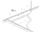
- Figure 1 shows a prior art ceiling system including ceiling panels 1 and a ceiling framework including support profiles 2 with vertical portions 3 and horizontal portions 4.
- the framework is hung below mainly parallel to the main (structural) ceiling by means of hooks 5.
- Figure 2 shows the ceiling system of figure 1 including spacing means 6 arranged to create a vertical gap and a horizontal gap between the profiles 2 and the panel 1, forming a continuous gap between the upper side and the lower side of the panel, having a vertical and a horizontal part.
- Figure 3 shows, as a preferred embodiment of the spacing means 6, an elongated part 7 interconnecting a series of spacing elements 8 which are intended to be mounted between the profiles 2 and the panel 1.
- the spacing elements 8 each consist of a vertical spacer 9 for spacing the side edge of the panel from the vertical profile surface, as well as a horizontal spacer 10 for spacing the lower surface of the panel from the upper surface of the horizontal portion of the support profile.
- the spacers 9 and 10 are interconnected by an interconnection part 11 which extends further to a side protrusion 12 provided on the elongated part 7.
- the elongated part 7 has the shape of a vertical wall which is arranged to deflect a ventilation stream, caused by overpressure at the upper side of the panels, passing the vertical and horizontal gaps between the panel and the vertical and horizontal profile portions, into downward direction, away from the lower horizontal) surface of the panel.
- the protrusion 12 functions as a (redundant) vertical spacer between the edge of the horizontal portion of the support profile and the deflection surface 13 of the elongated part 7.
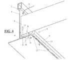
- Figure 4 shows the elongated part 7 of the spacing means 6, shown in figure 3 , wherein the spacing elements 8 have been installed between the (right) surface of the vertical part 3 and the upper surface of the horizontal part 4 of the support profile 2 and the (left) vertical side surface and the lower surface of the panel 1, wherein the elongated part 7 includes a vertical wall which is arranged to deflect the last part of a ventilation stream, originating from the plenum space above the panels and indicated by the arrows 13, 14 and 15, into downward direction, via a gap between said deflection wall/elongated part 7 and the side edge of the horizontal part 4 of the support profile 2.
Landscapes
- Engineering & Computer Science (AREA)
- Chemical & Material Sciences (AREA)
- Combustion & Propulsion (AREA)
- Mechanical Engineering (AREA)
- General Engineering & Computer Science (AREA)
- Building Environments (AREA)
Abstract
Ceiling system comprising a plurality of ceiling panels (1) and a ceiling framework for supporting those panels, the framework including panel support profiles (2) each including a vertical portion (3) and a horizontal portion (4), the ceiling system, moreover, comprising spacing means (6) arranged to create, per panel concerned, a vertical gap between relevant vertical portions of the profiles and at least one of the side edges of the panel, as well as a horizontal gap between relevant horizontal portions of the profiles and the horizontal lower surface of the panel. The spacing means may comprise an elongated part (7), in use extending mainly parallel to the vertical gap and horizontal gap and interconnecting a series of spacing elements (8) extending in the vertical gap and horizontal gap. The ceiling system may be arranged to be used in a ventilation system wherein an overpressure is provided at the top side relative to the lower side of the ceiling system, causing a ventilation stream (13-15) to flow from the top side to the lower side of the ceiling system via the vertical and horizontal gaps. The elongated part (7) may be arranged to deflect the ventilation stream, after having passed the horizontal gap, into a downward direction (15).
Description
- The present invention refers to a ceiling system comprising a plurality of ceiling panels and a ceiling framework for supporting those panels.
- In particular, however not exclusively, the invention refers to a so-called dropped ceiling system, i.e. a lowered (secondary) ceiling, hung below mainly parallel to the main (structural) ceiling. They may also be referred to as a drop ceiling, false ceiling, or suspended ceiling. The area above the dropped ceiling is called the plenum space, as it is sometimes used for HVAC air return. The plenum space is also very commonly used to conceal piping, wiring, and/or ductwork.
- A typical dropped ceiling consists of a grid-work of metal channels in the shape of an upside-down "T", suspended on wires from the overhead structure. These channels snap together in a regularly spaced pattern - typically a 2x2 or 2x4 foot grid in the US, or 600x600 mm grid in Europe. Each cell is filled with lightweight "tiles" or "panels" which simply drop into the grid. Tiles can be selected with a variety of materials, including wood, metal, plastic, or mineral fibers, and can come in almost any color. Light fixtures, HVAC air grilles, and other fixtures are available which can fit the same space as a tile for easy installation. Most tile material is easily cut to allow fixtures in other shapes, such as incandescent lights, speakers, and fire sprinkler heads.
- An earlier patent application
WO2009005344 of applicant discloses a ventilation method and system respectively for ventilating rooms like classrooms and the like, comprising a surface structure mainly extending parallel to the ceiling, and means for forced air inlet from the outside air into the room between said surface structure and the ceiling. Air outlet openings are provided, which are mainly evenly spaced over the whole surface of the surface structure. Preferably, the hydraulic diameter of the outlet openings is between 0.1 and 6 cm. The means for forced air inlet from the outside air into the room (or plenum space) between the surface structure and said wall, ceiling or floor are formed by an electrical ventilator. - In the embodiments shown in
WO2009005344 the panels concerned are provided with holes which can be made during the manufacturing process of the panels or -e.g. when already installed panels are used- by drilling. Disadvantageous is that - the holes have to be made, either during production or afterwards;
- panels with and without holes should be held in stock separately;
- the (plurality of) holes in the ceiling panels are considered to be not aesthetical.
- One aim of the present invention is to provide a system which e.g. is arranged to perform a method as presented in
W02009005344 , however without the obligation to provide -during or after their manufacture- the relevant panels with holes. - Another aim of the present invention is to provide means by which standard panels can be used, even if already installed in an existing ceiling system.
- According to the invention a ceiling system is provided comprising a plurality of ceiling panels and a ceiling framework for supporting those panels, said framework including panel support profiles each including a vertical portion and a horizontal portion, which ceiling system, preferably, comprises spacing means arranged to create, per panel concerned, a vertical gap between relevant vertical portions of the profiles and at least one of the side edges of the panel, as well as a horizontal gap between relevant horizontal portions of the profiles and the horizontal lower surface of the panel.
- By using spacing means for creating a vertical gap between the vertical portions of the profiles and the side edges of the panel, as well as a horizontal gap the horizontal portions of the profiles and the horizontal lower surface of the panel the panels don't need to be provided with ventilation holes. Moreover, standard panels can be used, even if already installed in an existing ceiling system. The ventilation gaps can be obtained by insertion of the spacing means between the panels concerned and the surrounding portions of the support frame.
- Preferably, the spacing means comprise an elongated part, extending, in use, mainly parallel to said vertical gap and horizontal gap and interconnecting a series of spacing elements extending in said vertical gap and horizontal gap.
- The ceiling system, preferably, is arranged to be used in a ventilation system wherein an overpressure is provided at the top side relative to the lower side of the ceiling, causing a ventilation stream to flow from the top side to the lower side of the ceiling via said vertical and horizontal gaps. To cause that the ventilation air mixes well with the below air mass in the room to be ventilated, the elongated part is, preferably, arranged to deflect said ventilation stream, after having passed said horizontal gap, into a downward direction. Preferably, the elongated part includes a mainly vertical wall, located opposite to the location of the vertical gap.
- Hereinafter the invention will be elucidated with reference to some figures.
- Figure 1
- shows a prior art ceiling system including ceiling panels and a ceiling framework including support profiles with vertical and horizontal portions.
- Figure 2
- shows the ceiling system of
figure 1 , however, including spacing means arranged to create a vertical gap and a horizontal gap between the profiles and the panel. - Figure 3
- shows an elongated part interconnecting a series of spacing elements intended to extend in a vertical gap and horizontal gap between the profiles and the panel.
- Figure 4
- shows the elongated part shown in
figure 3 wherein the spacing elements have been installed between parts of the profile and panel, wherein the elongated part includes a vertical wall arranged to deflect a ventilation stream into downward direction. -
Figure 1 shows a prior art ceiling system includingceiling panels 1 and a ceiling framework includingsupport profiles 2 withvertical portions 3 andhorizontal portions 4. The framework is hung below mainly parallel to the main (structural) ceiling by means ofhooks 5. -
Figure 2 shows the ceiling system offigure 1 including spacing means 6 arranged to create a vertical gap and a horizontal gap between theprofiles 2 and thepanel 1, forming a continuous gap between the upper side and the lower side of the panel, having a vertical and a horizontal part. -
Figure 3 shows, as a preferred embodiment of the spacing means 6, anelongated part 7 interconnecting a series ofspacing elements 8 which are intended to be mounted between theprofiles 2 and thepanel 1. Normally, four of suchelongated part 7, having a length equal to about the length or width of the panel, will be mounted per panel, thus creating a mainly continuous gap surrounding that panel. Thespacing elements 8 each consist of avertical spacer 9 for spacing the side edge of the panel from the vertical profile surface, as well as ahorizontal spacer 10 for spacing the lower surface of the panel from the upper surface of the horizontal portion of the support profile. Thespacers interconnection part 11 which extends further to aside protrusion 12 provided on theelongated part 7. Theelongated part 7 has the shape of a vertical wall which is arranged to deflect a ventilation stream, caused by overpressure at the upper side of the panels, passing the vertical and horizontal gaps between the panel and the vertical and horizontal profile portions, into downward direction, away from the lower horizontal) surface of the panel. Theprotrusion 12 functions as a (redundant) vertical spacer between the edge of the horizontal portion of the support profile and thedeflection surface 13 of theelongated part 7. -
Figure 4 shows theelongated part 7 of the spacing means 6, shown infigure 3 , wherein thespacing elements 8 have been installed between the (right) surface of thevertical part 3 and the upper surface of thehorizontal part 4 of thesupport profile 2 and the (left) vertical side surface and the lower surface of thepanel 1, wherein theelongated part 7 includes a vertical wall which is arranged to deflect the last part of a ventilation stream, originating from the plenum space above the panels and indicated by thearrows elongated part 7 and the side edge of thehorizontal part 4 of thesupport profile 2.
Claims (5)
- Ceiling system comprising a plurality of ceiling panels (1) and a ceiling framework for supporting those panels, said framework including panel support profiles (2) each including a vertical portion (3) and a horizontal portion (4), the ceiling system, moreover, comprising spacing means (6) arranged to create, per panel concerned, a vertical gap between relevant vertical portions of the profiles and at least one of the side edges of the panel, as well as a horizontal gap between relevant horizontal portions of the profiles and the horizontal lower surface of the panel.
- Ceiling system according to claim 1, said spacing means comprising an elongated part (7), in use extending mainly parallel to said vertical gap and horizontal gap and interconnecting a series of spacing elements (8) extending in said vertical gap and horizontal gap.
- Ceiling system according to claim 1 or 2, arranged to be used in a ventilation system wherein an overpressure is provided at the top side relative to the lower side of the ceiling system, causing a ventilation stream (13-15) to flow from the top side to the lower side of the ceiling system via said vertical and horizontal gaps.
- Ceiling system according to claim 2 and 3, wherein said elongated part (7) is arranged to deflect said ventilation stream, after having passed said horizontal gap, into a downward direction (15).
- Ceiling system according to claim 4, wherein said elongated part includes a mainly vertical wall (7) located opposite to the location of said vertical gap.
Priority Applications (3)
| Application Number | Priority Date | Filing Date | Title |
|---|---|---|---|
| EP10155585A EP2365152A1 (en) | 2010-03-05 | 2010-03-05 | Ceiling system with framework and panels and including means for creating ventilation gaps. |
| PCT/NL2011/050150 WO2011108928A1 (en) | 2010-03-05 | 2011-03-04 | Ceiling system and method for installing or modifying such a system |
| EP11708346.9A EP2542730B1 (en) | 2010-03-05 | 2011-03-04 | Ceiling system and method for installing or modifying such a system |
Applications Claiming Priority (1)
| Application Number | Priority Date | Filing Date | Title |
|---|---|---|---|
| EP10155585A EP2365152A1 (en) | 2010-03-05 | 2010-03-05 | Ceiling system with framework and panels and including means for creating ventilation gaps. |
Publications (1)
| Publication Number | Publication Date |
|---|---|
| EP2365152A1 true EP2365152A1 (en) | 2011-09-14 |
Family
ID=42557357
Family Applications (2)
| Application Number | Title | Priority Date | Filing Date |
|---|---|---|---|
| EP10155585A Ceased EP2365152A1 (en) | 2010-03-05 | 2010-03-05 | Ceiling system with framework and panels and including means for creating ventilation gaps. |
| EP11708346.9A Not-in-force EP2542730B1 (en) | 2010-03-05 | 2011-03-04 | Ceiling system and method for installing or modifying such a system |
Family Applications After (1)
| Application Number | Title | Priority Date | Filing Date |
|---|---|---|---|
| EP11708346.9A Not-in-force EP2542730B1 (en) | 2010-03-05 | 2011-03-04 | Ceiling system and method for installing or modifying such a system |
Country Status (2)
| Country | Link |
|---|---|
| EP (2) | EP2365152A1 (en) |
| WO (1) | WO2011108928A1 (en) |
Cited By (3)
| Publication number | Priority date | Publication date | Assignee | Title |
|---|---|---|---|---|
| CN110700475A (en) * | 2019-09-18 | 2020-01-17 | 上海金茂建筑装饰有限公司 | Assembled ceiling suspended top beam structure and assembling method thereof |
| EP3879044A1 (en) * | 2020-03-13 | 2021-09-15 | Saint-Gobain Ecophon AB | Ceiling tile and suspended ceiling system comprising such a ceiling tile |
| EP4246049A1 (en) * | 2022-03-14 | 2023-09-20 | Saint-Gobain Ecophon AB | A diffuse ceiling ventilation system |
Families Citing this family (1)
| Publication number | Priority date | Publication date | Assignee | Title |
|---|---|---|---|---|
| CN108951990B (en) * | 2018-08-14 | 2024-05-07 | 和能人居科技集团股份有限公司 | Assembled furred ceiling |
Citations (5)
| Publication number | Priority date | Publication date | Assignee | Title |
|---|---|---|---|---|
| US3207057A (en) * | 1962-09-07 | 1965-09-21 | Donn Prod Inc | Panel supporting grid |
| US3429250A (en) * | 1962-04-17 | 1969-02-25 | Wood Conversion Co | Ventilating ceiling construction |
| US3475869A (en) * | 1966-09-07 | 1969-11-04 | Chicago Metallic Sash Co | Ventilated suspended ceiling structure |
| US4611444A (en) * | 1985-02-28 | 1986-09-16 | Simplex Ceiling Corp. | Sanitary acoustical ceiling |
| WO2009005344A2 (en) | 2007-06-07 | 2009-01-08 | Nederlandse Organisatie Voor Toegepast-Natuurwetenschappelijk Onderzoek Tno | Ventilation system |
-
2010
- 2010-03-05 EP EP10155585A patent/EP2365152A1/en not_active Ceased
-
2011
- 2011-03-04 EP EP11708346.9A patent/EP2542730B1/en not_active Not-in-force
- 2011-03-04 WO PCT/NL2011/050150 patent/WO2011108928A1/en not_active Ceased
Patent Citations (5)
| Publication number | Priority date | Publication date | Assignee | Title |
|---|---|---|---|---|
| US3429250A (en) * | 1962-04-17 | 1969-02-25 | Wood Conversion Co | Ventilating ceiling construction |
| US3207057A (en) * | 1962-09-07 | 1965-09-21 | Donn Prod Inc | Panel supporting grid |
| US3475869A (en) * | 1966-09-07 | 1969-11-04 | Chicago Metallic Sash Co | Ventilated suspended ceiling structure |
| US4611444A (en) * | 1985-02-28 | 1986-09-16 | Simplex Ceiling Corp. | Sanitary acoustical ceiling |
| WO2009005344A2 (en) | 2007-06-07 | 2009-01-08 | Nederlandse Organisatie Voor Toegepast-Natuurwetenschappelijk Onderzoek Tno | Ventilation system |
Cited By (6)
| Publication number | Priority date | Publication date | Assignee | Title |
|---|---|---|---|---|
| CN110700475A (en) * | 2019-09-18 | 2020-01-17 | 上海金茂建筑装饰有限公司 | Assembled ceiling suspended top beam structure and assembling method thereof |
| EP3879044A1 (en) * | 2020-03-13 | 2021-09-15 | Saint-Gobain Ecophon AB | Ceiling tile and suspended ceiling system comprising such a ceiling tile |
| WO2021180644A1 (en) * | 2020-03-13 | 2021-09-16 | Saint-Gobain Ecophon Ab | Ceiling tile and suspended ceiling system comprising such a ceiling tile |
| US20230111321A1 (en) * | 2020-03-13 | 2023-04-13 | Saint-Gobain Ecophon Ab | Ceiling tile and suspended ceiling system comprising such a ceiling tile |
| EP4246049A1 (en) * | 2022-03-14 | 2023-09-20 | Saint-Gobain Ecophon AB | A diffuse ceiling ventilation system |
| WO2023174787A1 (en) | 2022-03-14 | 2023-09-21 | Saint-Gobain Ecophon Ab | A diffuse ceiling ventilation system |
Also Published As
| Publication number | Publication date |
|---|---|
| EP2542730A1 (en) | 2013-01-09 |
| EP2542730B1 (en) | 2013-12-11 |
| WO2011108928A1 (en) | 2011-09-09 |
Similar Documents
| Publication | Publication Date | Title |
|---|---|---|
| US12529225B2 (en) | Ceiling system | |
| US9739057B2 (en) | Ceiling system | |
| EP3775427B1 (en) | Vented suspension ceiling beam and suspension ceiling system | |
| US20120317915A1 (en) | Self-Hanging Notched Ceiling Tile | |
| EP2542730B1 (en) | Ceiling system and method for installing or modifying such a system | |
| EP1167648B1 (en) | Suspension system for false ceiling panels | |
| US3353472A (en) | Dropped ceiling ventilator apparatus | |
| US2884512A (en) | Overhead lighting and room conditioning system | |
| KR101352058B1 (en) | Ceiling Installing Structure | |
| EP2378023A1 (en) | Ceiling system with framework and panels and including means for creating ventilation gaps | |
| EP3656941A1 (en) | Vacuum insulation panel system | |
| JP6475999B2 (en) | Building ceiling structure | |
| JP6198598B2 (en) | Eave back ceiling structure | |
| EP2090707B1 (en) | Ceiling and method of arranging the same | |
| CN108603372B (en) | Suspended Wall Track System | |
| US20250361723A1 (en) | A ceiling apparatus and method thereof | |
| US20130239493A1 (en) | Suspended ceiling panel system for residential and commercial buildings | |
| EP2221426B1 (en) | A suspended ceiling and a method for supporting a suspended ceiling | |
| JP2024172717A (en) | Exterior body connection structure | |
| JPH03183846A (en) | system ceiling | |
| KR20170016624A (en) | Apparatus for constructing ceiling panel of the clean room |
Legal Events
| Date | Code | Title | Description |
|---|---|---|---|
| PUAI | Public reference made under article 153(3) epc to a published international application that has entered the european phase |
Free format text: ORIGINAL CODE: 0009012 |
|
| AK | Designated contracting states |
Kind code of ref document: A1 Designated state(s): AT BE BG CH CY CZ DE DK EE ES FI FR GB GR HR HU IE IS IT LI LT LU LV MC MK MT NL NO PL PT RO SE SI SK SM TR |
|
| AX | Request for extension of the european patent |
Extension state: AL BA ME RS |
|
| STAA | Information on the status of an ep patent application or granted ep patent |
Free format text: STATUS: THE APPLICATION HAS BEEN REFUSED |
|
| 18R | Application refused |
Effective date: 20111120 |