EP2365104A1 - Method for applying a thermal barrier coating - Google Patents
Method for applying a thermal barrier coating Download PDFInfo
- Publication number
- EP2365104A1 EP2365104A1 EP11157146A EP11157146A EP2365104A1 EP 2365104 A1 EP2365104 A1 EP 2365104A1 EP 11157146 A EP11157146 A EP 11157146A EP 11157146 A EP11157146 A EP 11157146A EP 2365104 A1 EP2365104 A1 EP 2365104A1
- Authority
- EP
- European Patent Office
- Prior art keywords
- substrate
- heating chamber
- heating
- oxidizing gas
- chamber
- Prior art date
- Legal status (The legal status is an assumption and is not a legal conclusion. Google has not performed a legal analysis and makes no representation as to the accuracy of the status listed.)
- Granted
Links
Images


Classifications
-
- C—CHEMISTRY; METALLURGY
- C23—COATING METALLIC MATERIAL; COATING MATERIAL WITH METALLIC MATERIAL; CHEMICAL SURFACE TREATMENT; DIFFUSION TREATMENT OF METALLIC MATERIAL; COATING BY VACUUM EVAPORATION, BY SPUTTERING, BY ION IMPLANTATION OR BY CHEMICAL VAPOUR DEPOSITION, IN GENERAL; INHIBITING CORROSION OF METALLIC MATERIAL OR INCRUSTATION IN GENERAL
- C23C—COATING METALLIC MATERIAL; COATING MATERIAL WITH METALLIC MATERIAL; SURFACE TREATMENT OF METALLIC MATERIAL BY DIFFUSION INTO THE SURFACE, BY CHEMICAL CONVERSION OR SUBSTITUTION; COATING BY VACUUM EVAPORATION, BY SPUTTERING, BY ION IMPLANTATION OR BY CHEMICAL VAPOUR DEPOSITION, IN GENERAL
- C23C28/00—Coating for obtaining at least two superposed coatings either by methods not provided for in a single one of groups C23C2/00 - C23C26/00 or by combinations of methods provided for in subclasses C23C and C25C or C25D
-
- C—CHEMISTRY; METALLURGY
- C23—COATING METALLIC MATERIAL; COATING MATERIAL WITH METALLIC MATERIAL; CHEMICAL SURFACE TREATMENT; DIFFUSION TREATMENT OF METALLIC MATERIAL; COATING BY VACUUM EVAPORATION, BY SPUTTERING, BY ION IMPLANTATION OR BY CHEMICAL VAPOUR DEPOSITION, IN GENERAL; INHIBITING CORROSION OF METALLIC MATERIAL OR INCRUSTATION IN GENERAL
- C23C—COATING METALLIC MATERIAL; COATING MATERIAL WITH METALLIC MATERIAL; SURFACE TREATMENT OF METALLIC MATERIAL BY DIFFUSION INTO THE SURFACE, BY CHEMICAL CONVERSION OR SUBSTITUTION; COATING BY VACUUM EVAPORATION, BY SPUTTERING, BY ION IMPLANTATION OR BY CHEMICAL VAPOUR DEPOSITION, IN GENERAL
- C23C30/00—Coating with metallic material characterised only by the composition of the metallic material, i.e. not characterised by the coating process
-
- C—CHEMISTRY; METALLURGY
- C23—COATING METALLIC MATERIAL; COATING MATERIAL WITH METALLIC MATERIAL; CHEMICAL SURFACE TREATMENT; DIFFUSION TREATMENT OF METALLIC MATERIAL; COATING BY VACUUM EVAPORATION, BY SPUTTERING, BY ION IMPLANTATION OR BY CHEMICAL VAPOUR DEPOSITION, IN GENERAL; INHIBITING CORROSION OF METALLIC MATERIAL OR INCRUSTATION IN GENERAL
- C23C—COATING METALLIC MATERIAL; COATING MATERIAL WITH METALLIC MATERIAL; SURFACE TREATMENT OF METALLIC MATERIAL BY DIFFUSION INTO THE SURFACE, BY CHEMICAL CONVERSION OR SUBSTITUTION; COATING BY VACUUM EVAPORATION, BY SPUTTERING, BY ION IMPLANTATION OR BY CHEMICAL VAPOUR DEPOSITION, IN GENERAL
- C23C8/00—Solid state diffusion of only non-metal elements into metallic material surfaces; Chemical surface treatment of metallic material by reaction of the surface with a reactive gas, leaving reaction products of surface material in the coating, e.g. conversion coatings, passivation of metals
- C23C8/06—Solid state diffusion of only non-metal elements into metallic material surfaces; Chemical surface treatment of metallic material by reaction of the surface with a reactive gas, leaving reaction products of surface material in the coating, e.g. conversion coatings, passivation of metals using gases
- C23C8/08—Solid state diffusion of only non-metal elements into metallic material surfaces; Chemical surface treatment of metallic material by reaction of the surface with a reactive gas, leaving reaction products of surface material in the coating, e.g. conversion coatings, passivation of metals using gases only one element being applied
- C23C8/10—Oxidising
-
- C—CHEMISTRY; METALLURGY
- C23—COATING METALLIC MATERIAL; COATING MATERIAL WITH METALLIC MATERIAL; CHEMICAL SURFACE TREATMENT; DIFFUSION TREATMENT OF METALLIC MATERIAL; COATING BY VACUUM EVAPORATION, BY SPUTTERING, BY ION IMPLANTATION OR BY CHEMICAL VAPOUR DEPOSITION, IN GENERAL; INHIBITING CORROSION OF METALLIC MATERIAL OR INCRUSTATION IN GENERAL
- C23C—COATING METALLIC MATERIAL; COATING MATERIAL WITH METALLIC MATERIAL; SURFACE TREATMENT OF METALLIC MATERIAL BY DIFFUSION INTO THE SURFACE, BY CHEMICAL CONVERSION OR SUBSTITUTION; COATING BY VACUUM EVAPORATION, BY SPUTTERING, BY ION IMPLANTATION OR BY CHEMICAL VAPOUR DEPOSITION, IN GENERAL
- C23C8/00—Solid state diffusion of only non-metal elements into metallic material surfaces; Chemical surface treatment of metallic material by reaction of the surface with a reactive gas, leaving reaction products of surface material in the coating, e.g. conversion coatings, passivation of metals
- C23C8/06—Solid state diffusion of only non-metal elements into metallic material surfaces; Chemical surface treatment of metallic material by reaction of the surface with a reactive gas, leaving reaction products of surface material in the coating, e.g. conversion coatings, passivation of metals using gases
- C23C8/08—Solid state diffusion of only non-metal elements into metallic material surfaces; Chemical surface treatment of metallic material by reaction of the surface with a reactive gas, leaving reaction products of surface material in the coating, e.g. conversion coatings, passivation of metals using gases only one element being applied
- C23C8/10—Oxidising
- C23C8/12—Oxidising using elemental oxygen or ozone
-
- C—CHEMISTRY; METALLURGY
- C23—COATING METALLIC MATERIAL; COATING MATERIAL WITH METALLIC MATERIAL; CHEMICAL SURFACE TREATMENT; DIFFUSION TREATMENT OF METALLIC MATERIAL; COATING BY VACUUM EVAPORATION, BY SPUTTERING, BY ION IMPLANTATION OR BY CHEMICAL VAPOUR DEPOSITION, IN GENERAL; INHIBITING CORROSION OF METALLIC MATERIAL OR INCRUSTATION IN GENERAL
- C23C—COATING METALLIC MATERIAL; COATING MATERIAL WITH METALLIC MATERIAL; SURFACE TREATMENT OF METALLIC MATERIAL BY DIFFUSION INTO THE SURFACE, BY CHEMICAL CONVERSION OR SUBSTITUTION; COATING BY VACUUM EVAPORATION, BY SPUTTERING, BY ION IMPLANTATION OR BY CHEMICAL VAPOUR DEPOSITION, IN GENERAL
- C23C8/00—Solid state diffusion of only non-metal elements into metallic material surfaces; Chemical surface treatment of metallic material by reaction of the surface with a reactive gas, leaving reaction products of surface material in the coating, e.g. conversion coatings, passivation of metals
- C23C8/06—Solid state diffusion of only non-metal elements into metallic material surfaces; Chemical surface treatment of metallic material by reaction of the surface with a reactive gas, leaving reaction products of surface material in the coating, e.g. conversion coatings, passivation of metals using gases
- C23C8/08—Solid state diffusion of only non-metal elements into metallic material surfaces; Chemical surface treatment of metallic material by reaction of the surface with a reactive gas, leaving reaction products of surface material in the coating, e.g. conversion coatings, passivation of metals using gases only one element being applied
- C23C8/10—Oxidising
- C23C8/12—Oxidising using elemental oxygen or ozone
- C23C8/14—Oxidising of ferrous surfaces
-
- C—CHEMISTRY; METALLURGY
- C23—COATING METALLIC MATERIAL; COATING MATERIAL WITH METALLIC MATERIAL; CHEMICAL SURFACE TREATMENT; DIFFUSION TREATMENT OF METALLIC MATERIAL; COATING BY VACUUM EVAPORATION, BY SPUTTERING, BY ION IMPLANTATION OR BY CHEMICAL VAPOUR DEPOSITION, IN GENERAL; INHIBITING CORROSION OF METALLIC MATERIAL OR INCRUSTATION IN GENERAL
- C23C—COATING METALLIC MATERIAL; COATING MATERIAL WITH METALLIC MATERIAL; SURFACE TREATMENT OF METALLIC MATERIAL BY DIFFUSION INTO THE SURFACE, BY CHEMICAL CONVERSION OR SUBSTITUTION; COATING BY VACUUM EVAPORATION, BY SPUTTERING, BY ION IMPLANTATION OR BY CHEMICAL VAPOUR DEPOSITION, IN GENERAL
- C23C8/00—Solid state diffusion of only non-metal elements into metallic material surfaces; Chemical surface treatment of metallic material by reaction of the surface with a reactive gas, leaving reaction products of surface material in the coating, e.g. conversion coatings, passivation of metals
- C23C8/06—Solid state diffusion of only non-metal elements into metallic material surfaces; Chemical surface treatment of metallic material by reaction of the surface with a reactive gas, leaving reaction products of surface material in the coating, e.g. conversion coatings, passivation of metals using gases
- C23C8/08—Solid state diffusion of only non-metal elements into metallic material surfaces; Chemical surface treatment of metallic material by reaction of the surface with a reactive gas, leaving reaction products of surface material in the coating, e.g. conversion coatings, passivation of metals using gases only one element being applied
- C23C8/10—Oxidising
- C23C8/16—Oxidising using oxygen-containing compounds, e.g. water, carbon dioxide
Definitions
- This disclosure relates to Electron Beam Physical Vapor Deposited Thermal Barrier Coatings (EB-PVD TBC) and methods for applying the same to a substrate in general, and to such coatings and methods that utilize a thermally grown oxide for ceramic to metallic adhesion in particular.
- EB-PVD TBC Electron Beam Physical Vapor Deposited Thermal Barrier Coatings
- Thermal barrier coating (TBC) systems have been developed to fulfill the demands placed on current high-temperature Ni-base superalloys for gas turbine applications in both aero engine and land based gas turbines.
- TBC systems typically consist of a ceramic (e.g., yttria-stabilized zirconia) top layer that has low thermal conductivity, is chemically inert in combustion atmospheres, and that is reasonably compatible with Ni-base superalloys.
- the ceramic top layer is often applied by a deposition process such as Electron Beam Physical Vapor Deposition (EB-PVD).
- EB-PVD Electron Beam Physical Vapor Deposition
- a bond coat e.g., NiCoCrAlY
- Ceramic adhesion to the bond coat depends on the formation of a thin, slow-growing oxide layer (also designated as TGO: thermally grown oxide) developing on the bond coat.
- TGOs grown from a NiCoCrAlY or similar bond coat in a vacuum (at about 10 0 to 10 -6 Torr) at temperatures less than 1800°F will include certain oxides (e.g., eta phase alumina, and transition oxides, also referred to herein as "low temperature oxides") that assume a voluminous, low integrity form that tend to have lower adhesion to the bond coat than other oxides. TBCs attached to these oxides will, therefore, be subject to these weaker bonds, and may be the basis for spallation.
- certain oxides e.g., eta phase alumina, and transition oxides, also referred to herein as "low temperature oxides”
- TBCs attached to these oxides will, therefore, be subject to these weaker bonds, and may be the basis for spallation.
- a method for forming thermally grown alpha alumina oxide scale on a substrate includes the steps of: a) providing a heating chamber having a heat source and an oxidizing gas source selectively operable to provide a stream of oxidizing gas; b) providing at least one substrate (e.g., airfoil, turbine blade, stator vane, etc.) disposed in the heating chamber, which substrate has a composition sufficient to permit formation of an alpha alumina scale on one or more surfaces; c) maintaining a vacuum in the heating chamber at a level that inhibits formation of one or more low temperature oxides on the one or more surfaces of the substrate; d) heating at least one of the one or more surfaces of the substrate to a predetermined temperature at or above 1800 degrees Fahrenheit; and e) directing the stream of oxidizing gas at a controlled rate to the one or more heated surfaces of the substrate.
- a substrate e.g., airfoil, turbine blade, stator vane, etc.
- a method for conditioning a surface of a substrate prior to coating the surface includes the steps of: a) providing a coating chamber and a heating chamber, which heating chamber has a heat source; b) treating one or more surfaces of a substrate within the heating chamber by establishing a vacuum in the heating chamber, heating a surface of the substrate to a predetermined temperature, and directing a stream of oxidizing gas to the heated one or more surfaces of the substrate to form an oxide layer thereon; and c) coating the treated surface of the substrate in the coating chamber.
- a system for forming a thermally grown oxide on a surface of at least one substrate includes a heating chamber, a vacuum pump, a heat source, and an oxidizing gas inlet.
- the heating chamber has a target location for locating the substrate.
- the vacuum pump is connected to the heating chamber and is selectively operable to establish a vacuum within the heating chamber.
- the heat source is disposed within the heating chamber, and is operable to radiate heat energy to the target location.
- the oxidizing gas inlet is disposed within the heating chamber, and is positioned to direct oxidizing gas to the target location for forming an oxide layer on the surface of the substrate.
- a coating system 10 adapted to treat and coat a surface of at least one substrate 14 (e.g., a turbine blade airfoil for a gas turbine engine) is shown.
- the coating system 10 includes a plurality of successive vacuum chambers (e.g., a pre-heat chamber 16, a coating chamber18) connected together via one or more gate valves 20, 22, 24.
- the coating system 10 further includes a transportation system 25 that directs the substrate 14 through the vacuum chambers 16, 18.
- the vacuum chambers 16, 18 are connected to at least one vacuum pump 26 (e.g., a diffusion pump).
- the coating system 10 may include additional vacuum chambers such as, but not limited to, a load-lock chamber, or a post-treatment chamber, or any combination thereof.
- the preheating chamber 16 is adapted to maintain a vacuum at or below approximately 10 -4 Torr (e.g., between approximately 10 -4 to 10 -6 Torr).
- the requisite vacuum may vary slightly depending upon the application at hand, thereby necessitating a preheating chamber adapted accordingly.
- the preheating chamber 16 has a target location 28 for locating the substrate 14 during a treatment / pre-treatment process, and houses a vacuum pump inlet 30 (hereinafter “vacuum inlet”), a radiant heat source 32 (hereinafter “heat source”), and at least one oxidizing gas inlet 34 (hereinafter “gas inlet”).
- the vacuum inlet 30 connects the diffusion pump to the preheating chamber 16.
- the heat source 32 is adapted to heat the surface 12 of the substrate 14. Surface 12 of the substrate 14 is aligned to receive the radiant heating from the heating source.
- the gas inlet 34 connects an oxidizing gas source 36 (hereinafter “gas source”) to the preheating chamber 16.
- the heat source 32 includes one or more heating elements 38 and an acceptor plate 40 (hereinafter “acceptor”).
- acceptor The heating elements 38 and the acceptor 40 are aligned such that thermal heat energy (hereinafter “heat energy”) radiates from the heating elements 38 to the surface 12 of the substrate 14 through the acceptor 40.
- the acceptor 40 includes one or more flow apertures 42 that extend between first and second acceptor surfaces 44, 46 (e.g., top and bottom surfaces).
- each flow aperture 42 is configured to receive and orientate a respective one of the gas inlets 34 such that oxidizing gas injected therefrom is directed to the surface 12 of the substrate 14.
- the heat source 32 can include a plurality of acceptors, where adjacent acceptors are spaced to receive and orientate at least one of the gas inlets.
- the acceptor 40 can be constructed from any suitable material such as, but not limited to, graphite or graphite composite.
- the coating chamber 18 is configured to deposit, for example, a ceramic (e.g., a TBC) coating on the surface of the substrate 14 by an EB-PVD process.
- EB-PVD coating chambers are well known in the art, and the present invention is not limited to any particular configuration thereof.
- suitable EB-PVD coating chambers and processes are disclosed in U.S. Patent No. 5,087,477 to Giggins, Jr. et al. , and U.S. Publication No. 2008/0160171 (Appln. No. 11/647,960) to Barabash et al. , which are hereby incorporated by reference in their entirety.
- the transportation system 25 includes a sting shaft 48 operable to move a sting 50 (i.e., a substrate carriage device), and thus the substrate 14, through the vacuum chambers 16, 18.
- the sting 50 can be adapted to adjust / manipulate the spatial position (e.g., height, etc.) and/or orientation (e.g., pitch, roll, etc.) of the substrate 14 in the vacuum chambers 16, 18.
- Such substrate transportation systems are well known in the art, and the present invention is not limited to any particular configuration thereof.
- the transportation system 25 includes a conveyor and a robotic manipulator disposed in each vacuum chamber 16, 18.
- a vacuum below approximately 10 -4 Torr (e.g., between approximately 10 -4 to 10 -6 Torr), is established and maintained in the preheating chamber 16 via the vacuum inlet 30 and the diffusion pump 26.
- the substrate 14 is directed, through a first gate valve 20, into the preheating chamber 16, and is positioned in the target location 28 via the sting 50 such that the surface 12 of the substrate 14 that is to be treated is aligned with (i.e., faces) the heat source 32 (e.g., the heating elements 38 and the acceptor 40).
- gas 52 e.g., oxidizing gases like oxygen or carbon dioxide
- gas 52 flows from a top region of the preheating chamber 16, for example proximate the heat source 32, creating a partial pressure adjacent surface 12; i.e., on the heated side of substrate 14.
- the heat source 32 heats the surface 12 of the substrate 14 via thermal radiation to a temperature above approximately 1800 °F.
- an acceptable substrate surface temperature range is about 1800 °F to about 1950 °F, and substrate surface temperatures above 1830 °F work particularly well.
- the heating elements 38 radiate heat energy 54 to the top surface 44 of the acceptor 40.
- the heat energy 54 disperses therethrough and radiates, in a substantially even / uniform pattern, from its bottom surface 46 to the surface 12 of the substrate 14. Referring to FIG.
- the surface 12 of the substrate 14 oxidizes, forming various oxides thereon such as theta phase alumina, nickel oxide, cobalt oxide, chromium oxide, etc..
- Low temperature ( ⁇ 1800 °F) phases of alumina and metallic oxides like nickel oxide, cobalt oxide and chromium oxide are loosely adherent and create a low integrity link between the metallic and ceramic as compared to thermally grown alpha alumina scale.
- With sufficiently high vacuum and a very small amount of time during ramp up between 700 and 1800 °F, the formation of theta phase alumina, and other metallic oxides like nickel oxide, cobalt oxide, chrome oxide, etc. will be relatively minor.
- the oxidization reaction primarily forms a layer of alpha alumina on the surface 12 of the substrate 14 (e.g., on the NiCoCrAlY bond coat).
- theta phase alumina will be transformed into alpha alumina.
- a cohesive alpha alumina scale or layer i.e., serves as a "metallic - ceramic bond" is desirable.
- Other thermally grown oxides can adversely affect TBC ceramic adhesion.
- the surface temperature of the substrate 14 should be rapidly heated above 1800 °F (e.g., to or above approximately 1830 °F) to reduce the quantity of the undesirable theta phase alumina, and other undesirable metallic oxides, that may form on the surface 12 of the bond coated substrate 14 at temperatures below 1800 °F.
- the gas source 36 injects, via each gas inlet 34, a stream of oxidizing gas 56 into the preheating chamber 16 for impingement against the heated surface 12 of the substrate 14 creating conditions promoting alpha alumina formation.
- the oxidizing gas 56 is directed from the gas inlet 34 to the heated surface 12 of the substrate 14.
- a controlled flow of oxidizing gas 56 provides oxygen (i.e., reactants) that directly influences the formation rate of alpha alumina on the heated surface 12 of the substrate 14.
- the flow of oxidizing gas is provided only after the surface 12 temperature of the substrate 14 has increased above 1800 °F (e.g., to 1830 °F).
- 1800 °F e.g., to 1830 °F.
- the substrate 14 can be re-orientated (e.g., rotated, shifted, etc.) such that each portion of the surface is successively aligned with (e.g., directly below) the heat source 32
- side and bottom surfaces 58, 60 of the substrate 14 can be treated (i.e., heated) by rotating the substrate 14 about, for example, its longitudinal axis such that each respective surface 12, 58, 60 is aligned with and treated by the heat source 32.
- the rotational speed is controlled / regulated, via the sting 50, such that a substantial portion of the surface of the substrate 14 that is aligned with the heat source 32 is maintained at or above approximately 1800 °F (e.g., at or above approximately 1830 °F).
- the substrate 14 is directed, via the sting 50, from the preheating chamber 16 to the coating chamber 18 through a respective second gate valve 22.
- the surface 12 of the substrate 14 is coated with, for example, a ceramic (e.g., TBC, etc.).
- the coating can be applied using any suitable deposition process such as, but not limited to, electron beam physical vapor deposition.
- the substrate 14 is directed, through a respective third gate valve 24, out of the coating chamber 18 and the coating system 10.
- the flow chart shown in FIG. 5 summarizes the present process.
Landscapes
- Chemical & Material Sciences (AREA)
- Chemical Kinetics & Catalysis (AREA)
- Engineering & Computer Science (AREA)
- Materials Engineering (AREA)
- Mechanical Engineering (AREA)
- Metallurgy (AREA)
- Organic Chemistry (AREA)
- Physical Vapour Deposition (AREA)
Abstract
Description
- This disclosure relates to Electron Beam Physical Vapor Deposited Thermal Barrier Coatings (EB-PVD TBC) and methods for applying the same to a substrate in general, and to such coatings and methods that utilize a thermally grown oxide for ceramic to metallic adhesion in particular.
- Thermal barrier coating (TBC) systems have been developed to fulfill the demands placed on current high-temperature Ni-base superalloys for gas turbine applications in both aero engine and land based gas turbines. TBC systems typically consist of a ceramic (e.g., yttria-stabilized zirconia) top layer that has low thermal conductivity, is chemically inert in combustion atmospheres, and that is reasonably compatible with Ni-base superalloys. The ceramic top layer is often applied by a deposition process such as Electron Beam Physical Vapor Deposition (EB-PVD). To ensure adequate bonding between the ceramic topcoat and the metallic substrate, it is common (but not required) to use a bond coat (e.g., NiCoCrAlY) disposed between the ceramic top coat and the metallic substrate. Ceramic adhesion to the bond coat depends on the formation of a thin, slow-growing oxide layer (also designated as TGO: thermally grown oxide) developing on the bond coat.
- TGOs grown from a NiCoCrAlY or similar bond coat in a vacuum (at about 100 to 10-6 Torr) at temperatures less than 1800°F will include certain oxides (e.g., eta phase alumina, and transition oxides, also referred to herein as "low temperature oxides") that assume a voluminous, low integrity form that tend to have lower adhesion to the bond coat than other oxides. TBCs attached to these oxides will, therefore, be subject to these weaker bonds, and may be the basis for spallation.
- According to one aspect of the invention, a method for forming thermally grown alpha alumina oxide scale on a substrate is provided. The method includes the steps of: a) providing a heating chamber having a heat source and an oxidizing gas source selectively operable to provide a stream of oxidizing gas; b) providing at least one substrate (e.g., airfoil, turbine blade, stator vane, etc.) disposed in the heating chamber, which substrate has a composition sufficient to permit formation of an alpha alumina scale on one or more surfaces; c) maintaining a vacuum in the heating chamber at a level that inhibits formation of one or more low temperature oxides on the one or more surfaces of the substrate; d) heating at least one of the one or more surfaces of the substrate to a predetermined temperature at or above 1800 degrees Fahrenheit; and e) directing the stream of oxidizing gas at a controlled rate to the one or more heated surfaces of the substrate.
- According to another aspect of the invention, a method for conditioning a surface of a substrate prior to coating the surface is provided. The method includes the steps of: a) providing a coating chamber and a heating chamber, which heating chamber has a heat source; b) treating one or more surfaces of a substrate within the heating chamber by establishing a vacuum in the heating chamber, heating a surface of the substrate to a predetermined temperature, and directing a stream of oxidizing gas to the heated one or more surfaces of the substrate to form an oxide layer thereon; and c) coating the treated surface of the substrate in the coating chamber.
- According to still another aspect of the invention, a system for forming a thermally grown oxide on a surface of at least one substrate is provided. The system includes a heating chamber, a vacuum pump, a heat source, and an oxidizing gas inlet. The heating chamber has a target location for locating the substrate. The vacuum pump is connected to the heating chamber and is selectively operable to establish a vacuum within the heating chamber. The heat source is disposed within the heating chamber, and is operable to radiate heat energy to the target location. The oxidizing gas inlet is disposed within the heating chamber, and is positioned to direct oxidizing gas to the target location for forming an oxide layer on the surface of the substrate.
- The foregoing features of the invention will become more apparent in light of the following description and the accompanying drawings.
-
-
FIG. 1 is a side sectional diagrammatic illustration of one embodiment of a coating system for heating and coating a surface of at least one substrate. -
FIG. 2 is a top view diagrammatic illustration of one embodiment of an acceptor that is included in a heating chamber of the coating system inFIG. 1 . -
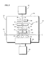
FIG. 3 diagrammatically illustrates a process for treating the surface of the substrate in the heating chamber. -
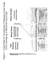
FIG. 4 graphically illustrates formation growth rates of alumina scales on the surface of a substrate versus the surface temperature of the substrate. -
FIG. 5 is a flow chart illustrating an aspect of the present method. - Now referring to
FIG. 1 , acoating system 10 adapted to treat and coat a surface of at least one substrate 14 (e.g., a turbine blade airfoil for a gas turbine engine) is shown. Thecoating system 10 includes a plurality of successive vacuum chambers (e.g., apre-heat chamber 16, a coating chamber18) connected together via one ormore gate valves coating system 10 further includes atransportation system 25 that directs thesubstrate 14 through thevacuum chambers vacuum chambers coating system 10 may include additional vacuum chambers such as, but not limited to, a load-lock chamber, or a post-treatment chamber, or any combination thereof. - The
preheating chamber 16 is adapted to maintain a vacuum at or below approximately 10-4 Torr (e.g., between approximately 10-4 to 10-6 Torr). The requisite vacuum may vary slightly depending upon the application at hand, thereby necessitating a preheating chamber adapted accordingly. Thepreheating chamber 16 has atarget location 28 for locating thesubstrate 14 during a treatment / pre-treatment process, and houses a vacuum pump inlet 30 (hereinafter "vacuum inlet"), a radiant heat source 32 (hereinafter "heat source"), and at least one oxidizing gas inlet 34 (hereinafter "gas inlet"). Thevacuum inlet 30 connects the diffusion pump to thepreheating chamber 16. Theheat source 32 is adapted to heat thesurface 12 of thesubstrate 14.Surface 12 of thesubstrate 14 is aligned to receive the radiant heating from the heating source. Thegas inlet 34 connects an oxidizing gas source 36 (hereinafter "gas source") to thepreheating chamber 16. - In the specific embodiment illustrated in
FIG. 1 , theheat source 32 includes one ormore heating elements 38 and an acceptor plate 40 (hereinafter "acceptor"). Theheating elements 38 and theacceptor 40 are aligned such that thermal heat energy (hereinafter "heat energy") radiates from theheating elements 38 to thesurface 12 of thesubstrate 14 through theacceptor 40. Now referring toFIGS. 1-2 , theacceptor 40 includes one ormore flow apertures 42 that extend between first andsecond acceptor surfaces 44, 46 (e.g., top and bottom surfaces). Referring again toFIG. 1 , eachflow aperture 42 is configured to receive and orientate a respective one of thegas inlets 34 such that oxidizing gas injected therefrom is directed to thesurface 12 of thesubstrate 14. The present invention, however, is not limited to the aforesaid embodiment. For example, in an alternate embodiment, theheat source 32 can include a plurality of acceptors, where adjacent acceptors are spaced to receive and orientate at least one of the gas inlets. Theacceptor 40 can be constructed from any suitable material such as, but not limited to, graphite or graphite composite. - The
coating chamber 18 is configured to deposit, for example, a ceramic (e.g., a TBC) coating on the surface of thesubstrate 14 by an EB-PVD process. EB-PVD coating chambers are well known in the art, and the present invention is not limited to any particular configuration thereof. Some examples of suitable EB-PVD coating chambers and processes are disclosed inU.S. Patent No. 5,087,477 to Giggins, Jr. et al. , andU.S. Publication No. 2008/0160171 (Appln. No.11/647,960) to Barabash et al. - In the embodiment in
FIG. 1 , thetransportation system 25 includes asting shaft 48 operable to move a sting 50 (i.e., a substrate carriage device), and thus thesubstrate 14, through thevacuum chambers sting 50 can be adapted to adjust / manipulate the spatial position (e.g., height, etc.) and/or orientation (e.g., pitch, roll, etc.) of thesubstrate 14 in thevacuum chambers transportation system 25 includes a conveyor and a robotic manipulator disposed in eachvacuum chamber - Referring to
FIG. 3 , during operation, a vacuum, below approximately 10-4 Torr (e.g., between approximately 10-4 to 10-6 Torr), is established and maintained in thepreheating chamber 16 via thevacuum inlet 30 and thediffusion pump 26. Thesubstrate 14 is directed, through afirst gate valve 20, into thepreheating chamber 16, and is positioned in thetarget location 28 via thesting 50 such that thesurface 12 of thesubstrate 14 that is to be treated is aligned with (i.e., faces) the heat source 32 (e.g., theheating elements 38 and the acceptor 40). Under vacuum, gas 52 (e.g., oxidizing gases like oxygen or carbon dioxide) flows from a top region of thepreheating chamber 16, for example proximate theheat source 32, creating a partial pressureadjacent surface 12; i.e., on the heated side ofsubstrate 14. - The
heat source 32 heats thesurface 12 of thesubstrate 14 via thermal radiation to a temperature above approximately 1800 °F. For most applications, an acceptable substrate surface temperature range is about 1800 °F to about 1950 °F, and substrate surface temperatures above 1830 °F work particularly well. For example, in the embodiment inFIGS. 1 and3 , theheating elements 38 radiateheat energy 54 to thetop surface 44 of theacceptor 40. In theacceptor 40, theheat energy 54 disperses therethrough and radiates, in a substantially even / uniform pattern, from itsbottom surface 46 to thesurface 12 of thesubstrate 14. Referring toFIG. 4 , as the surface temperature of thesubstrate 14 rises rapidly to approximately 1800 °F, thesurface 12 of thesubstrate 14 oxidizes, forming various oxides thereon such as theta phase alumina, nickel oxide, cobalt oxide, chromium oxide, etc.. Low temperature (<1800 °F) phases of alumina and metallic oxides like nickel oxide, cobalt oxide and chromium oxide are loosely adherent and create a low integrity link between the metallic and ceramic as compared to thermally grown alpha alumina scale. With sufficiently high vacuum and a very small amount of time during ramp up between 700 and 1800 °F, the formation of theta phase alumina, and other metallic oxides like nickel oxide, cobalt oxide, chrome oxide, etc. will be relatively minor. When the temperature of thesurface 12 ofsubstrate 14 rises above approximately 1800 °F (e.g., to or above approximately 1830 °F), the oxidization reaction primarily forms a layer of alpha alumina on thesurface 12 of the substrate 14 (e.g., on the NiCoCrAlY bond coat). In addition, at least a portion of the previously formed theta phase alumina will be transformed into alpha alumina. - Thus, for favorable adhesion of TBC ceramic on a bond coat (or on a substrate or other coating), a cohesive alpha alumina scale or layer (i.e., serves as a "metallic - ceramic bond") is desirable. Other thermally grown oxides can adversely affect TBC ceramic adhesion. The surface temperature of the
substrate 14 should be rapidly heated above 1800 °F (e.g., to or above approximately 1830 °F) to reduce the quantity of the undesirable theta phase alumina, and other undesirable metallic oxides, that may form on thesurface 12 of the bond coatedsubstrate 14 at temperatures below 1800 °F. - Referring again to
FIG. 3 , when the surface temperature of thesubstrate 14 has risen to or above approximately 1800 °F (e.g., to or above approximately 1830 °F), thegas source 36 injects, via eachgas inlet 34, a stream of oxidizinggas 56 into the preheatingchamber 16 for impingement against theheated surface 12 of thesubstrate 14 creating conditions promoting alpha alumina formation. For example, in the embodiment inFIGS. 1 and3 , the oxidizinggas 56 is directed from thegas inlet 34 to theheated surface 12 of thesubstrate 14. A controlled flow of oxidizinggas 56 provides oxygen (i.e., reactants) that directly influences the formation rate of alpha alumina on theheated surface 12 of thesubstrate 14. The flow of oxidizing gas is provided only after thesurface 12 temperature of thesubstrate 14 has increased above 1800 °F (e.g., to 1830 °F). As a result, the conditions promote the formation of desirable alpha alumina and decrease the potential for the formation of undesirable oxides like theta phase alumina on thesurface 12 of thesubstrate 14. - To forum the alpha alumina layer on a large, compound, and/or irregular surface, the
substrate 14 can be re-orientated (e.g., rotated, shifted, etc.) such that each portion of the surface is successively aligned with (e.g., directly below) theheat source 32 For example, referring toFIGS. 1 and3 , side andbottom surfaces substrate 14 can be treated (i.e., heated) by rotating thesubstrate 14 about, for example, its longitudinal axis such that eachrespective surface heat source 32. In some embodiments, the rotational speed is controlled / regulated, via thesting 50, such that a substantial portion of the surface of thesubstrate 14 that is aligned with theheat source 32 is maintained at or above approximately 1800 °F (e.g., at or above approximately 1830 °F). - After the TGO is developed on the coating required surface of
substrate 14 treated in the preheatingchamber 16, thesubstrate 14 is directed, via thesting 50, from the preheatingchamber 16 to thecoating chamber 18 through a respectivesecond gate valve 22. In thecoating chamber 18, thesurface 12 of thesubstrate 14 is coated with, for example, a ceramic (e.g., TBC, etc.). The coating can be applied using any suitable deposition process such as, but not limited to, electron beam physical vapor deposition. When the surface of thesubstrate 14 has been coated, thesubstrate 14 is directed, through a respectivethird gate valve 24, out of thecoating chamber 18 and thecoating system 10. The flow chart shown inFIG. 5 summarizes the present process. - While various embodiments of the present invention have been disclosed, it will be apparent to those of ordinary skill in the art that many more embodiments and implementations are possible within the scope of the invention. Accordingly, the present invention is not to be restricted except in light of the attached claims and their equivalents.
Claims (14)
- A method for forming thermally grown alpha alumina oxide scale on a substrate (14), comprising:providing a heating chamber (16) having a heat source (32) and an oxidizing gas source (36) selectively operable to provide a stream of oxidizing gas;providing at least one substrate (14) disposed in the heating chamber (16), which substrate (14) has a composition sufficient to permit formation of an alpha alumina scale on one or more surfaces (12);maintaining a vacuum in the heating chamber (16) at a level that inhibits formation of one or more low temperature oxides on the one or more surfaces (12) of the substrate (14);heating at least one of the one or more surfaces (12) of the substrate (14) to a predetermined temperature at or above 1800 degrees Fahrenheit; anddirecting the stream of oxidizing gas at a controlled rate toward one or more heated surfaces (12) of the substrate (14).
- The method of claim 1, wherein the vacuum is established at or below approximately 10-3 Torr (10-3 1 to 10-8 Torr).
- The method of claim 1 or 2, wherein the step of heating at least one of the one or more surfaces (12) of the substrate (14) includes radiating heat energy from a heating element (38), through an acceptor (40), to the surface (12) of the substrate (14).
- The method of claim 3, further comprising injecting the stream of oxidizing gas through the acceptor (40) directly toward the substrate (14).
- The method of any preceding claim further comprising coating the surface (12) in a coating chamber (18) after the formation of the oxide scale thereon.
- A method for conditioning a surface (12) of a substrate (14) prior to coating the surface, comprising the steps of:providing a coating chamber (18) and a heating chamber (16), which heating chamber (16) has a heat source (32);treating one or more surfaces of a substrate (12) within the heating chamber (16) by:establishing a vacuum in the heating chamber (16);heating a surface (12) of the substrate (14) to a predetermined temperature; anddirecting a stream of oxidizing gas toward the heated one or more surfaces (12) of the substrate (14) to form an oxide layer thereon; andcoating the treated surface (12) of the substrate (14) in the coating chamber (16).
- The method of claim 6, wherein the vacuum is established at or below approximately 10-3 Torr.
- The method of claim 6 or 7, wherein the one or more surfaces (12) of the substrate (14) are heated to a temperature greater than or equal to approximately 1800 degrees Fahrenheit.
- The method of claim 6, 7 or 8, wherein the step of heating the surface (12) of the substrate (14) includes radiating heat energy from a heating element (38), through an acceptor (40), to the surface (12) of the substrate (14).
- The method of claim 8, further comprising injecting the stream of oxidizing gas through a gas inlet (34) disposed with the acceptor (40).
- A system for forming a thermally grown oxide on a surface of at least one substrate (14), comprising:a heating chamber (16) having a target location (28) for locating the substrate (14);a vacuum pump (26) connected to the heating chamber (16), which pump (26) is selectively operable to establish a vacuum within the heating chamber (16);a heat source (32) disposed within the heating chamber (16), which heat source (32) is operable to radiate heat energy to the target location (28); andan oxidizing gas inlet (34) disposed within the heating chamber (16), the inlet (34) positioned to direct oxidizing gas toward the target location (28) for forming an oxide layer on the surface of the substrate (14).
- The system of claim 11, wherein the heat source (32) includes one or more heating elements (38) and an acceptor (40), which acceptor (40) is aligned between the heating elements (38) and the target location (28).
- The system of claim 12, wherein the acceptor (40) includes at least one flow aperture (42) configured to receive the oxidizing gas inlet (34).
- The system of any of claims 11 to 13, further comprising a coating chamber (18) connected to the heating chamber (16) and adapted to coat the surface of the substrate (14).
Applications Claiming Priority (1)
| Application Number | Priority Date | Filing Date | Title |
|---|---|---|---|
| US12/719,594 US8481117B2 (en) | 2010-03-08 | 2010-03-08 | Method for applying a thermal barrier coating |
Publications (2)
| Publication Number | Publication Date |
|---|---|
| EP2365104A1 true EP2365104A1 (en) | 2011-09-14 |
| EP2365104B1 EP2365104B1 (en) | 2014-04-23 |
Family
ID=43836787
Family Applications (1)
| Application Number | Title | Priority Date | Filing Date |
|---|---|---|---|
| EP11157146.9A Not-in-force EP2365104B1 (en) | 2010-03-08 | 2011-03-07 | Method for applying a thermal barrier coating |
Country Status (2)
| Country | Link |
|---|---|
| US (1) | US8481117B2 (en) |
| EP (1) | EP2365104B1 (en) |
Cited By (1)
| Publication number | Priority date | Publication date | Assignee | Title |
|---|---|---|---|---|
| EP2971221A4 (en) * | 2013-03-14 | 2016-10-05 | United Technologies Corp | PRE-HEATING CHAMBER OXIDATION METHOD |
Families Citing this family (1)
| Publication number | Priority date | Publication date | Assignee | Title |
|---|---|---|---|---|
| CN113804004B (en) * | 2021-08-12 | 2024-03-19 | 上海富乐华半导体科技有限公司 | Methods to improve the reliability of the oxide layer on the surface of the sintering furnace conveyor belt |
Citations (7)
| Publication number | Priority date | Publication date | Assignee | Title |
|---|---|---|---|---|
| EP0366924A2 (en) * | 1988-11-03 | 1990-05-09 | AlliedSignal Inc. | Ceramic thermal barrier coating with alumina interlayer |
| US5087477A (en) | 1990-02-05 | 1992-02-11 | United Technologies Corporation | Eb-pvd method for applying ceramic coatings |
| EP0733723A1 (en) * | 1995-03-21 | 1996-09-25 | Howmet Corporation | Thermal barrier coating system |
| EP0926257A1 (en) * | 1997-12-23 | 1999-06-30 | United Technologies Corporation | Pre-oxidation method |
| EP1908857A2 (en) * | 2006-10-05 | 2008-04-09 | General Electric Company | Method for forming a thermal barrier coating |
| US20080160171A1 (en) | 2006-12-29 | 2008-07-03 | United Technologies Corporation | Electron beam physical vapor deposition apparatus and processes for adjusting the feed rate of a target and manufacturing a multi-component condensate free of lamination |
| EP2180077A1 (en) * | 2008-10-24 | 2010-04-28 | United Technologies Corporation | Method of depositing a ceramic coating |
Family Cites Families (20)
| Publication number | Priority date | Publication date | Assignee | Title |
|---|---|---|---|---|
| US4676994A (en) * | 1983-06-15 | 1987-06-30 | The Boc Group, Inc. | Adherent ceramic coatings |
| US4952556A (en) * | 1987-12-08 | 1990-08-28 | General Motors Corporation | Patterning thin film superconductors using focused beam techniques |
| JPH03150341A (en) * | 1989-11-07 | 1991-06-26 | Onoda Cement Co Ltd | Conjugate torch type plasma generator and plasma generating method using the same |
| US6143081A (en) * | 1996-07-12 | 2000-11-07 | Tokyo Electron Limited | Film forming apparatus and method, and film modifying apparatus and method |
| US6301434B1 (en) * | 1998-03-23 | 2001-10-09 | Mattson Technology, Inc. | Apparatus and method for CVD and thermal processing of semiconductor substrates |
| US6143079A (en) * | 1998-11-19 | 2000-11-07 | Asm America, Inc. | Compact process chamber for improved process uniformity |
| US6607789B1 (en) * | 2001-04-26 | 2003-08-19 | General Electric Company | Plasma sprayed thermal bond coat system |
| US6576067B2 (en) * | 2001-08-31 | 2003-06-10 | General Electric Co. | Fabrication of an article having a protective coating with a polished, pre-oxidized protective-coating surface |
| WO2003068503A1 (en) * | 2002-02-14 | 2003-08-21 | Iowa State University Research Foundation, Inc. | Novel friction and wear-resistant coatings for tools, dies and microelectromechanical systems |
| US6730422B2 (en) * | 2002-08-21 | 2004-05-04 | United Technologies Corporation | Thermal barrier coatings with low thermal conductivity |
| US7226672B2 (en) * | 2002-08-21 | 2007-06-05 | United Technologies Corporation | Turbine components with thermal barrier coatings |
| US7326470B2 (en) * | 2004-04-28 | 2008-02-05 | United Technologies Corporation | Thin 7YSZ, interfacial layer as cyclic durability (spallation) life enhancement for low conductivity TBCs |
| EP1746185A1 (en) * | 2005-07-22 | 2007-01-24 | Stichting Voor De Technische Wetenschappen | Method for providing a thermal barrier coating and substrate having such coating |
| US7422771B2 (en) * | 2005-09-01 | 2008-09-09 | United Technologies Corporation | Methods for applying a hybrid thermal barrier coating |
| JP2007158123A (en) * | 2005-12-06 | 2007-06-21 | Kobe Steel Ltd | Heating device |
| US7622195B2 (en) * | 2006-01-10 | 2009-11-24 | United Technologies Corporation | Thermal barrier coating compositions, processes for applying same and articles coated with same |
| US7455913B2 (en) * | 2006-01-10 | 2008-11-25 | United Technologies Corporation | Thermal barrier coating compositions, processes for applying same and articles coated with same |
| US7579087B2 (en) * | 2006-01-10 | 2009-08-25 | United Technologies Corporation | Thermal barrier coating compositions, processes for applying same and articles coated with same |
| US7662489B2 (en) * | 2006-01-20 | 2010-02-16 | United Technologies Corporation | Durable reactive thermal barrier coatings |
| US7476450B2 (en) * | 2006-03-24 | 2009-01-13 | United Technologies Corporation | Coating suitable for use as a bondcoat in a thermal barrier coating system |
-
2010
- 2010-03-08 US US12/719,594 patent/US8481117B2/en not_active Expired - Fee Related
-
2011
- 2011-03-07 EP EP11157146.9A patent/EP2365104B1/en not_active Not-in-force
Patent Citations (7)
| Publication number | Priority date | Publication date | Assignee | Title |
|---|---|---|---|---|
| EP0366924A2 (en) * | 1988-11-03 | 1990-05-09 | AlliedSignal Inc. | Ceramic thermal barrier coating with alumina interlayer |
| US5087477A (en) | 1990-02-05 | 1992-02-11 | United Technologies Corporation | Eb-pvd method for applying ceramic coatings |
| EP0733723A1 (en) * | 1995-03-21 | 1996-09-25 | Howmet Corporation | Thermal barrier coating system |
| EP0926257A1 (en) * | 1997-12-23 | 1999-06-30 | United Technologies Corporation | Pre-oxidation method |
| EP1908857A2 (en) * | 2006-10-05 | 2008-04-09 | General Electric Company | Method for forming a thermal barrier coating |
| US20080160171A1 (en) | 2006-12-29 | 2008-07-03 | United Technologies Corporation | Electron beam physical vapor deposition apparatus and processes for adjusting the feed rate of a target and manufacturing a multi-component condensate free of lamination |
| EP2180077A1 (en) * | 2008-10-24 | 2010-04-28 | United Technologies Corporation | Method of depositing a ceramic coating |
Cited By (1)
| Publication number | Priority date | Publication date | Assignee | Title |
|---|---|---|---|---|
| EP2971221A4 (en) * | 2013-03-14 | 2016-10-05 | United Technologies Corp | PRE-HEATING CHAMBER OXIDATION METHOD |
Also Published As
| Publication number | Publication date |
|---|---|
| US20110217464A1 (en) | 2011-09-08 |
| US8481117B2 (en) | 2013-07-09 |
| EP2365104B1 (en) | 2014-04-23 |
Similar Documents
| Publication | Publication Date | Title |
|---|---|---|
| Feuerstein et al. | Technical and economical aspects of current thermal barrier coating systems for gas turbine engines by thermal spray and EBPVD: a review | |
| Rezanka et al. | Improved thermal cycling durability of thermal barrier coatings manufactured by PS-PVD | |
| US4916022A (en) | Titania doped ceramic thermal barrier coatings | |
| US6929825B2 (en) | Method for aluminide coating of gas turbine engine blade | |
| JP5209228B2 (en) | Method for producing a coating | |
| US6168874B1 (en) | Diffusion aluminide bond coat for a thermal barrier coating system and method therefor | |
| US7879411B2 (en) | Method and apparatus for efficient application of substrate coating | |
| US6905730B2 (en) | Aluminide coating of turbine engine component | |
| EP2179816B1 (en) | A method of repairing a coating on an article | |
| CN102534460A (en) | Method for producing a thermal insulation layer construction | |
| EP1209247A1 (en) | CVD aluminiding process for producing a modified platinum aluminide bond coat for improved high temperature performance | |
| KR20070077056A (en) | Cmas resistant thermal barrier coating | |
| EP2258889B1 (en) | Method and apparatus for applying a thermal barrier coating | |
| US7026011B2 (en) | Aluminide coating of gas turbine engine blade | |
| EP2236642B1 (en) | Controlled oxidation of bond coat | |
| EP2365104B1 (en) | Method for applying a thermal barrier coating | |
| US20070172678A1 (en) | Thermal barrier coating system and process therefor | |
| EP2947174B1 (en) | Method for slurry aluminide coating repair | |
| US20170314119A1 (en) | Methods of forming a multilayer thermal barrier coating system | |
| US11092019B2 (en) | Coated component and method of preparing a coated component | |
| EP3470543A1 (en) | Coated component and method of preparing a coated component | |
| US8367160B2 (en) | Coating method for reactive metal | |
| JP4643546B2 (en) | Method for applying bonding coat and heat insulation film on aluminide surface | |
| EP2942421B1 (en) | Method and system for controlling coating in non-line-of-sight locations | |
| US20030211245A1 (en) | Fabrication of an article having a thermal barrier coating system, and the article |
Legal Events
| Date | Code | Title | Description |
|---|---|---|---|
| PUAI | Public reference made under article 153(3) epc to a published international application that has entered the european phase |
Free format text: ORIGINAL CODE: 0009012 |
|
| AK | Designated contracting states |
Kind code of ref document: A1 Designated state(s): AL AT BE BG CH CY CZ DE DK EE ES FI FR GB GR HR HU IE IS IT LI LT LU LV MC MK MT NL NO PL PT RO RS SE SI SK SM TR |
|
| AX | Request for extension of the european patent |
Extension state: BA ME |
|
| 17P | Request for examination filed |
Effective date: 20120313 |
|
| 17Q | First examination report despatched |
Effective date: 20120822 |
|
| GRAP | Despatch of communication of intention to grant a patent |
Free format text: ORIGINAL CODE: EPIDOSNIGR1 |
|
| INTG | Intention to grant announced |
Effective date: 20130813 |
|
| GRAP | Despatch of communication of intention to grant a patent |
Free format text: ORIGINAL CODE: EPIDOSNIGR1 |
|
| INTG | Intention to grant announced |
Effective date: 20140127 |
|
| GRAS | Grant fee paid |
Free format text: ORIGINAL CODE: EPIDOSNIGR3 |
|
| GRAA | (expected) grant |
Free format text: ORIGINAL CODE: 0009210 |
|
| AK | Designated contracting states |
Kind code of ref document: B1 Designated state(s): AL AT BE BG CH CY CZ DE DK EE ES FI FR GB GR HR HU IE IS IT LI LT LU LV MC MK MT NL NO PL PT RO RS SE SI SK SM TR |
|
| REG | Reference to a national code |
Ref country code: GB Ref legal event code: FG4D |
|
| REG | Reference to a national code |
Ref country code: CH Ref legal event code: EP |
|
| REG | Reference to a national code |
Ref country code: AT Ref legal event code: REF Ref document number: 663931 Country of ref document: AT Kind code of ref document: T Effective date: 20140515 |
|
| REG | Reference to a national code |
Ref country code: IE Ref legal event code: FG4D |
|
| REG | Reference to a national code |
Ref country code: DE Ref legal event code: R096 Ref document number: 602011006310 Country of ref document: DE Effective date: 20140605 |
|
| REG | Reference to a national code |
Ref country code: AT Ref legal event code: MK05 Ref document number: 663931 Country of ref document: AT Kind code of ref document: T Effective date: 20140423 |
|
| REG | Reference to a national code |
Ref country code: NL Ref legal event code: VDEP Effective date: 20140423 |
|
| REG | Reference to a national code |
Ref country code: LT Ref legal event code: MG4D |
|
| PG25 | Lapsed in a contracting state [announced via postgrant information from national office to epo] |
Ref country code: GR Free format text: LAPSE BECAUSE OF FAILURE TO SUBMIT A TRANSLATION OF THE DESCRIPTION OR TO PAY THE FEE WITHIN THE PRESCRIBED TIME-LIMIT Effective date: 20140724 Ref country code: CY Free format text: LAPSE BECAUSE OF FAILURE TO SUBMIT A TRANSLATION OF THE DESCRIPTION OR TO PAY THE FEE WITHIN THE PRESCRIBED TIME-LIMIT Effective date: 20140423 Ref country code: LT Free format text: LAPSE BECAUSE OF FAILURE TO SUBMIT A TRANSLATION OF THE DESCRIPTION OR TO PAY THE FEE WITHIN THE PRESCRIBED TIME-LIMIT Effective date: 20140423 Ref country code: FI Free format text: LAPSE BECAUSE OF FAILURE TO SUBMIT A TRANSLATION OF THE DESCRIPTION OR TO PAY THE FEE WITHIN THE PRESCRIBED TIME-LIMIT Effective date: 20140423 Ref country code: BG Free format text: LAPSE BECAUSE OF FAILURE TO SUBMIT A TRANSLATION OF THE DESCRIPTION OR TO PAY THE FEE WITHIN THE PRESCRIBED TIME-LIMIT Effective date: 20140723 Ref country code: NL Free format text: LAPSE BECAUSE OF FAILURE TO SUBMIT A TRANSLATION OF THE DESCRIPTION OR TO PAY THE FEE WITHIN THE PRESCRIBED TIME-LIMIT Effective date: 20140423 Ref country code: IS Free format text: LAPSE BECAUSE OF FAILURE TO SUBMIT A TRANSLATION OF THE DESCRIPTION OR TO PAY THE FEE WITHIN THE PRESCRIBED TIME-LIMIT Effective date: 20140823 Ref country code: NO Free format text: LAPSE BECAUSE OF FAILURE TO SUBMIT A TRANSLATION OF THE DESCRIPTION OR TO PAY THE FEE WITHIN THE PRESCRIBED TIME-LIMIT Effective date: 20140723 |
|
| PG25 | Lapsed in a contracting state [announced via postgrant information from national office to epo] |
Ref country code: LV Free format text: LAPSE BECAUSE OF FAILURE TO SUBMIT A TRANSLATION OF THE DESCRIPTION OR TO PAY THE FEE WITHIN THE PRESCRIBED TIME-LIMIT Effective date: 20140423 Ref country code: ES Free format text: LAPSE BECAUSE OF FAILURE TO SUBMIT A TRANSLATION OF THE DESCRIPTION OR TO PAY THE FEE WITHIN THE PRESCRIBED TIME-LIMIT Effective date: 20140423 Ref country code: SE Free format text: LAPSE BECAUSE OF FAILURE TO SUBMIT A TRANSLATION OF THE DESCRIPTION OR TO PAY THE FEE WITHIN THE PRESCRIBED TIME-LIMIT Effective date: 20140423 Ref country code: AT Free format text: LAPSE BECAUSE OF FAILURE TO SUBMIT A TRANSLATION OF THE DESCRIPTION OR TO PAY THE FEE WITHIN THE PRESCRIBED TIME-LIMIT Effective date: 20140423 Ref country code: HR Free format text: LAPSE BECAUSE OF FAILURE TO SUBMIT A TRANSLATION OF THE DESCRIPTION OR TO PAY THE FEE WITHIN THE PRESCRIBED TIME-LIMIT Effective date: 20140423 Ref country code: RS Free format text: LAPSE BECAUSE OF FAILURE TO SUBMIT A TRANSLATION OF THE DESCRIPTION OR TO PAY THE FEE WITHIN THE PRESCRIBED TIME-LIMIT Effective date: 20140423 Ref country code: PL Free format text: LAPSE BECAUSE OF FAILURE TO SUBMIT A TRANSLATION OF THE DESCRIPTION OR TO PAY THE FEE WITHIN THE PRESCRIBED TIME-LIMIT Effective date: 20140423 |
|
| PG25 | Lapsed in a contracting state [announced via postgrant information from national office to epo] |
Ref country code: PT Free format text: LAPSE BECAUSE OF FAILURE TO SUBMIT A TRANSLATION OF THE DESCRIPTION OR TO PAY THE FEE WITHIN THE PRESCRIBED TIME-LIMIT Effective date: 20140825 |
|
| REG | Reference to a national code |
Ref country code: DE Ref legal event code: R097 Ref document number: 602011006310 Country of ref document: DE |
|
| PG25 | Lapsed in a contracting state [announced via postgrant information from national office to epo] |
Ref country code: BE Free format text: LAPSE BECAUSE OF FAILURE TO SUBMIT A TRANSLATION OF THE DESCRIPTION OR TO PAY THE FEE WITHIN THE PRESCRIBED TIME-LIMIT Effective date: 20140423 Ref country code: EE Free format text: LAPSE BECAUSE OF FAILURE TO SUBMIT A TRANSLATION OF THE DESCRIPTION OR TO PAY THE FEE WITHIN THE PRESCRIBED TIME-LIMIT Effective date: 20140423 Ref country code: DK Free format text: LAPSE BECAUSE OF FAILURE TO SUBMIT A TRANSLATION OF THE DESCRIPTION OR TO PAY THE FEE WITHIN THE PRESCRIBED TIME-LIMIT Effective date: 20140423 Ref country code: SK Free format text: LAPSE BECAUSE OF FAILURE TO SUBMIT A TRANSLATION OF THE DESCRIPTION OR TO PAY THE FEE WITHIN THE PRESCRIBED TIME-LIMIT Effective date: 20140423 Ref country code: RO Free format text: LAPSE BECAUSE OF FAILURE TO SUBMIT A TRANSLATION OF THE DESCRIPTION OR TO PAY THE FEE WITHIN THE PRESCRIBED TIME-LIMIT Effective date: 20140423 Ref country code: CZ Free format text: LAPSE BECAUSE OF FAILURE TO SUBMIT A TRANSLATION OF THE DESCRIPTION OR TO PAY THE FEE WITHIN THE PRESCRIBED TIME-LIMIT Effective date: 20140423 |
|
| PLBE | No opposition filed within time limit |
Free format text: ORIGINAL CODE: 0009261 |
|
| STAA | Information on the status of an ep patent application or granted ep patent |
Free format text: STATUS: NO OPPOSITION FILED WITHIN TIME LIMIT |
|
| PG25 | Lapsed in a contracting state [announced via postgrant information from national office to epo] |
Ref country code: IT Free format text: LAPSE BECAUSE OF FAILURE TO SUBMIT A TRANSLATION OF THE DESCRIPTION OR TO PAY THE FEE WITHIN THE PRESCRIBED TIME-LIMIT Effective date: 20140423 |
|
| 26N | No opposition filed |
Effective date: 20150126 |
|
| REG | Reference to a national code |
Ref country code: DE Ref legal event code: R097 Ref document number: 602011006310 Country of ref document: DE Effective date: 20150126 |
|
| PG25 | Lapsed in a contracting state [announced via postgrant information from national office to epo] |
Ref country code: SI Free format text: LAPSE BECAUSE OF FAILURE TO SUBMIT A TRANSLATION OF THE DESCRIPTION OR TO PAY THE FEE WITHIN THE PRESCRIBED TIME-LIMIT Effective date: 20140423 |
|
| PG25 | Lapsed in a contracting state [announced via postgrant information from national office to epo] |
Ref country code: LU Free format text: LAPSE BECAUSE OF FAILURE TO SUBMIT A TRANSLATION OF THE DESCRIPTION OR TO PAY THE FEE WITHIN THE PRESCRIBED TIME-LIMIT Effective date: 20150307 Ref country code: MC Free format text: LAPSE BECAUSE OF FAILURE TO SUBMIT A TRANSLATION OF THE DESCRIPTION OR TO PAY THE FEE WITHIN THE PRESCRIBED TIME-LIMIT Effective date: 20140423 |
|
| REG | Reference to a national code |
Ref country code: CH Ref legal event code: PL |
|
| REG | Reference to a national code |
Ref country code: IE Ref legal event code: MM4A |
|
| PG25 | Lapsed in a contracting state [announced via postgrant information from national office to epo] |
Ref country code: IE Free format text: LAPSE BECAUSE OF NON-PAYMENT OF DUE FEES Effective date: 20150307 Ref country code: CH Free format text: LAPSE BECAUSE OF NON-PAYMENT OF DUE FEES Effective date: 20150331 Ref country code: LI Free format text: LAPSE BECAUSE OF NON-PAYMENT OF DUE FEES Effective date: 20150331 |
|
| REG | Reference to a national code |
Ref country code: FR Ref legal event code: PLFP Year of fee payment: 6 |
|
| PG25 | Lapsed in a contracting state [announced via postgrant information from national office to epo] |
Ref country code: MT Free format text: LAPSE BECAUSE OF FAILURE TO SUBMIT A TRANSLATION OF THE DESCRIPTION OR TO PAY THE FEE WITHIN THE PRESCRIBED TIME-LIMIT Effective date: 20140423 |
|
| REG | Reference to a national code |
Ref country code: FR Ref legal event code: PLFP Year of fee payment: 7 |
|
| REG | Reference to a national code |
Ref country code: FR Ref legal event code: CA Effective date: 20170324 |
|
| PG25 | Lapsed in a contracting state [announced via postgrant information from national office to epo] |
Ref country code: SM Free format text: LAPSE BECAUSE OF FAILURE TO SUBMIT A TRANSLATION OF THE DESCRIPTION OR TO PAY THE FEE WITHIN THE PRESCRIBED TIME-LIMIT Effective date: 20140423 Ref country code: HU Free format text: LAPSE BECAUSE OF FAILURE TO SUBMIT A TRANSLATION OF THE DESCRIPTION OR TO PAY THE FEE WITHIN THE PRESCRIBED TIME-LIMIT; INVALID AB INITIO Effective date: 20110307 |
|
| REG | Reference to a national code |
Ref country code: DE Ref legal event code: R082 Ref document number: 602011006310 Country of ref document: DE Representative=s name: SCHMITT-NILSON SCHRAUD WAIBEL WOHLFROM PATENTA, DE |
|
| REG | Reference to a national code |
Ref country code: DE Ref legal event code: R082 Ref document number: 602011006310 Country of ref document: DE Representative=s name: SCHMITT-NILSON SCHRAUD WAIBEL WOHLFROM PATENTA, DE Ref country code: DE Ref legal event code: R081 Ref document number: 602011006310 Country of ref document: DE Owner name: UNITED TECHNOLOGIES CORP. (N.D.GES.D. STAATES , US Free format text: FORMER OWNER: UNITED TECHNOLOGIES CORP., HARTFORD, CONN., US |
|
| PG25 | Lapsed in a contracting state [announced via postgrant information from national office to epo] |
Ref country code: TR Free format text: LAPSE BECAUSE OF FAILURE TO SUBMIT A TRANSLATION OF THE DESCRIPTION OR TO PAY THE FEE WITHIN THE PRESCRIBED TIME-LIMIT Effective date: 20140423 |
|
| REG | Reference to a national code |
Ref country code: FR Ref legal event code: PLFP Year of fee payment: 8 |
|
| PG25 | Lapsed in a contracting state [announced via postgrant information from national office to epo] |
Ref country code: MK Free format text: LAPSE BECAUSE OF FAILURE TO SUBMIT A TRANSLATION OF THE DESCRIPTION OR TO PAY THE FEE WITHIN THE PRESCRIBED TIME-LIMIT Effective date: 20140423 |
|
| PG25 | Lapsed in a contracting state [announced via postgrant information from national office to epo] |
Ref country code: AL Free format text: LAPSE BECAUSE OF FAILURE TO SUBMIT A TRANSLATION OF THE DESCRIPTION OR TO PAY THE FEE WITHIN THE PRESCRIBED TIME-LIMIT Effective date: 20140423 |
|
| REG | Reference to a national code |
Ref country code: DE Ref legal event code: R081 Ref document number: 602011006310 Country of ref document: DE Owner name: RAYTHEON TECHNOLOGIES CORPORATION (N.D.GES.D.S, US Free format text: FORMER OWNER: UNITED TECHNOLOGIES CORP. (N.D.GES.D. STAATES DELAWARE), FARMINGTON, CONN., US |
|
| P01 | Opt-out of the competence of the unified patent court (upc) registered |
Effective date: 20230519 |
|
| PGFP | Annual fee paid to national office [announced via postgrant information from national office to epo] |
Ref country code: DE Payment date: 20240220 Year of fee payment: 14 Ref country code: GB Payment date: 20240220 Year of fee payment: 14 |
|
| PGFP | Annual fee paid to national office [announced via postgrant information from national office to epo] |
Ref country code: FR Payment date: 20240220 Year of fee payment: 14 |
|
| REG | Reference to a national code |
Ref country code: DE Ref legal event code: R119 Ref document number: 602011006310 Country of ref document: DE |
|
| GBPC | Gb: european patent ceased through non-payment of renewal fee |
Effective date: 20250307 |
|
| PG25 | Lapsed in a contracting state [announced via postgrant information from national office to epo] |
Ref country code: DE Free format text: LAPSE BECAUSE OF NON-PAYMENT OF DUE FEES Effective date: 20251001 |
|
| PG25 | Lapsed in a contracting state [announced via postgrant information from national office to epo] |
Ref country code: GB Free format text: LAPSE BECAUSE OF NON-PAYMENT OF DUE FEES Effective date: 20250307 |
|
| PG25 | Lapsed in a contracting state [announced via postgrant information from national office to epo] |
Ref country code: FR Free format text: LAPSE BECAUSE OF NON-PAYMENT OF DUE FEES Effective date: 20250331 |