EP2364808A1 - Apparatus and method for preferential formation of weld join - Google Patents
Apparatus and method for preferential formation of weld join Download PDFInfo
- Publication number
- EP2364808A1 EP2364808A1 EP11157514A EP11157514A EP2364808A1 EP 2364808 A1 EP2364808 A1 EP 2364808A1 EP 11157514 A EP11157514 A EP 11157514A EP 11157514 A EP11157514 A EP 11157514A EP 2364808 A1 EP2364808 A1 EP 2364808A1
- Authority
- EP
- European Patent Office
- Prior art keywords
- piece
- weld
- flange
- nailhead
- post
- Prior art date
- Legal status (The legal status is an assumption and is not a legal conclusion. Google has not performed a legal analysis and makes no representation as to the accuracy of the status listed.)
- Granted
Links
Images

Classifications
-
- B—PERFORMING OPERATIONS; TRANSPORTING
- B23—MACHINE TOOLS; METAL-WORKING NOT OTHERWISE PROVIDED FOR
- B23K—SOLDERING OR UNSOLDERING; WELDING; CLADDING OR PLATING BY SOLDERING OR WELDING; CUTTING BY APPLYING HEAT LOCALLY, e.g. FLAME CUTTING; WORKING BY LASER BEAM
- B23K15/00—Electron-beam welding or cutting
- B23K15/0046—Welding
- B23K15/0053—Seam welding
-
- Y—GENERAL TAGGING OF NEW TECHNOLOGICAL DEVELOPMENTS; GENERAL TAGGING OF CROSS-SECTIONAL TECHNOLOGIES SPANNING OVER SEVERAL SECTIONS OF THE IPC; TECHNICAL SUBJECTS COVERED BY FORMER USPC CROSS-REFERENCE ART COLLECTIONS [XRACs] AND DIGESTS
- Y10—TECHNICAL SUBJECTS COVERED BY FORMER USPC
- Y10T—TECHNICAL SUBJECTS COVERED BY FORMER US CLASSIFICATION
- Y10T29/00—Metal working
- Y10T29/49—Method of mechanical manufacture
- Y10T29/49316—Impeller making
-
- Y—GENERAL TAGGING OF NEW TECHNOLOGICAL DEVELOPMENTS; GENERAL TAGGING OF CROSS-SECTIONAL TECHNOLOGIES SPANNING OVER SEVERAL SECTIONS OF THE IPC; TECHNICAL SUBJECTS COVERED BY FORMER USPC CROSS-REFERENCE ART COLLECTIONS [XRACs] AND DIGESTS
- Y10—TECHNICAL SUBJECTS COVERED BY FORMER USPC
- Y10T—TECHNICAL SUBJECTS COVERED BY FORMER US CLASSIFICATION
- Y10T428/00—Stock material or miscellaneous articles
- Y10T428/12—All metal or with adjacent metals
- Y10T428/12493—Composite; i.e., plural, adjacent, spatially distinct metal components [e.g., layers, joint, etc.]
- Y10T428/12771—Transition metal-base component
- Y10T428/12861—Group VIII or IB metal-base component
- Y10T428/12944—Ni-base component
Definitions
- the present invention relates generally to welding, and more particularly, to embodiments of a weld set-up and welding process that may form a weld joint with preferential geometry that alleviates micro-cracking among the pieces adjoined by the weld joint.
- weld joints and their associated features can also have undesirable defects, which may be detrimental to the strength, reliability, or overall longevity of the weld joint and the resulting welded structure. These defects may cause problems within the welded structure, and more particularly, such defects may include micro-cracks and other deviations in the welded structure adjoined by the weld joint. Micro-cracks may further propagate to a point that results in failure of the weld joint and/or other more catastrophic failure events.
- This preferential geometry may, in one embodiment, locate in selective regions of the welded pieces features such as nailheads particular to the weld joint and/or the welding technique. These selective regions may be removed from the resulting welded structure in a manner that may substantially remove defects associated generally with the weld joint, and in particular examples, the regions that are removed may include micro-cracks associated with the nailheads.
- a method for reducing micro-cracks induced by an electron welding beam can comprise steps for providing a first part having a surface facing the welding beam, and abutting a second part to the first part to form a weld joint, the second part including a flange extending over the surface.
- the method can be further described where the first part and the second part form a work-piece that includes a sacrificial portion and a working portion separated from the sacrificial portion by a post-processing zone.
- the method can be yet further described where the second part receives the electron welding beam with welding parameters that cause a first nailhead to form exclusively in the first part.
- an apparatus prepared for weld by an electron welding beam can comprise a first part having a surface facing the electron welding beam, and a second part abutting the first part to form a weld joint, the second part including a flange extending away from the weld joint over the surface of the first part.
- the apparatus can be further described where the first part and the second part form a work-piece that includes a sacrificial portion and a working portion separated from the sacrificial portion by a post-processing zone.
- the sacrificial portion includes the flange.
- embodiments of the present invention are directed to welding methods and apparatus implemented in a manner that controls certain characteristics of a weld.
- welding methodology in which the geometry of the weld is manipulated so that particular features (e.g., nailheads) of the weld are situated in preferential locations as between two welded pieces.
- This preferential location permits implementation of post-weld processes to remove these preferentially located features without disturbing the functionality of the remaining welded work-piece.
- This manipulation of the weld and/or weld joint is particularly beneficial to electron beam welding techniques and related implementations because the preferential location of the nailhead permits removal of imperfections and defects such as areas of micro-cracking associated with, and in the vicinity of, the nailhead.
- the welding set-up 100 may comprise a primary piece 102 and a secondary piece 104 secured to the primary piece 102 by a weld joint 106 to form a welded work-piece 108.
- the primary piece 102 may comprise an upper surface 110 and a primary abutment surface 112 that in the present example is illustrated as being substantially perpendicular to the upper surface 110.
- the secondary piece 104 may comprise a flange portion 114 with an end surface 116, the flange portion 114 being configured to extend over the upper surface 110 a relative distance 118 as measured between the weld joint 106 and the end surface 116.
- the flange portion 114 may also comprise a bottom flange surface 120 that may form an interface 122 with the upper surface 110 of the primary piece 102.
- the interface 122 may be a gap or void between the upper surface 110 and the bottom flange surface 120.
- the secondary piece 104 may also comprise a secondary abutment surface 124 configured to abut with the primary abutment surface 112 in a manner that permits formation of the weld joint 106 upon application of a welding beam 126.
- the welding set-up 100 and related welding methods discussed below may be applied to a variety of materials and part production techniques.
- Combinations of cast and wrought metals, for example, are compatible with the concepts disclosed herein so as to permit construction of the welded work-piece 108 with formation of one or more nailheads in locations that permit substantial removal of micro-cracking associated with the nailhead.
- More particular configurations are contemplated in which one or more of the primary piece 102 and the secondary piece 104 (collectively "the welded pieces”) are cast, forged, drawn, rolled, or produced using similarly suitable production techniques.
- Each of the welded pieces 102, 104 may likewise comprise materials with varying composition such as may be found in metal alloys and similar composite materials. At a relatively high level, these alloys and composites may comprise one or more of nickel, aluminum, titanium, chromium, cobalt, and molybdenum, among many others. More particular implementations of the concepts disclosed herein may be used in connection with certain "superalloys," which may comprise one or more of these materials (and their composites and derivations) in varying weight percentages.
- the welded pieces may comprise WASPALOY® manufactured by United Technologies Corporation of Harford, CT.
- the secondary piece 104 may be formed monolithically to incorporate the flange portion 114 and other structural features unilaterally with the remainder of the secondary piece 104. This construction may be accomplished using various machining techniques that may, for example, for from a single piece of material the flange portion 114 and the secondary abutment surface 124. These techniques may also be used to prepare the secondary abutment surface 124 and/or the primary abutment surface 112 so that each is configured to maximize effectiveness of the weld joint 106. Moreover, material thickness of the flange portion 114 may vary based on, for example, properties of the weld beam 126, which may influence the size and location of, e.g., the nailheads.
- the flange portion 114 may have a relative thickness from about 2 mm to about 6 mm.
- the overall thickness of the welded pieces may also vary, with one or more of the welded pieces having a material thickness from about 7 mm to about 25 mm. In one example, the material thickness may be at least about 12 mm for at least one of the primary piece 102 and the secondary piece 104.
- the weld set-up 100 may also comprise means for clamping, which is illustrated generally in Fig. 1 as a plurality of loading vectors 128.
- the means may be used to secure together the primary piece 102 and the secondary piece 104 prior to and during the application of weld beam 126 to form the weld joint 106.
- the loading vectors 128 designate by example certain possible directions upon which the means for clamping can be implemented to secure the welding set-up 100.
- the load vectors 128 may be orthogonal to the welded pieces 102, 104. Clamps, vices, vice grips, as well as customized rigging, forms, and fixtures are contemplated as suitable for applying and maintaining one or more of the loads 128.
- the configuration, orientation, and association of the welded pieces can likewise be manipulated such as by thermal expansion and/or contraction of the welded pieces to apply and maintain forces exemplified by one or more of the load vectors 128.
- the loads 128 may be so applied to minimize the interface 122, and in one particular construction, contact may occur between the upper surface 110 and the bottom flange surface 120.
- Fig. 2 there is provided a cross-section of another exemplary embodiment of a weld set-up 200 that is made in accordance with the present invention.
- Like numerals are used to identify like components as between Figs. 1 and 2 , except that the numerals have been increased by 100 (e.g., 100 is now 200 in Fig. 2 ).
- the weld set-up 200 of Fig. 2 may comprise a primary part 202, a secondary part 204, and a weld joint 206.
- the weld set-up 200 may also comprise a sacrificial portion 230, a working portion 232, and a post-processing portion 234 with a post-processing machining line 236 that separates the sacrificial portion 230 from the working portion 232.
- the weld set-up 200 may comprise a weld zone 238 that may incorporate portions of both the primary piece 202 and the secondary piece 204 such as defined by the HAZ resulting from application of the welding beam 226.
- the weld zone 238 may also comprise weld features 240 such as nailheads 242 that are formations typically associated with application of the weld beam 226 (e.g., an electron beam), and in one particular construction the nailheads 242 may comprise a primary nailhead 244 and a preferential nailhead 246, both of which may form in response to the selected welding technique for use as the welding beam 226.
- the welding technique may be conventional electron beam welding.
- the primary nailhead 244 and the preferential nailhead 246 may comprise one or more nailhead portions 248.
- the formation of the nailhead portions 248 is generally understood by those artisans knowledgeable in the welding arts, and thus additional details are not necessary.
- configurations of the welding pieces may promote preferential location of the nailheads 242.
- This preferential location may define, in one example, the location of the primary nailhead 244, the preferential nailhead 246, as well as the distribution, location, and/or size of the nailhead portions 248.
- the configuration of the welding pieces 202, 204 may facilitate formation in the secondary piece 204 of the primary nailhead 244 with a pair of primary nailhead portions 250.
- this configuration promotes formation in the primary piece 202 of the preferential nailhead 246 with a preferential nailhead portion 252.
- the location of the preferential nailhead portion 252 exclusively in the primary piece 202, in combination with the lack of any complementary nailhead portion of the preferential nailhead 246 co-located in the secondary piece 204, is beneficial because the resulting preferential geometry effectively re-locates areas of micro-cracking to desired portions of the weld set-up 200.
- the preferential geometry may locate an area of micro-cracking 254 outside of the working portion 232 such as in the sacrificial portion 230.
- Post-process techniques such as machining along the post-processing machining line 236 may be employed to separate the sacrificial portion 230 from the working portion 232. This separation removes the area of micro-cracking 254 that may effectively leave the working portion 232, and more particularly the secondary piece 204, free from, e.g., micro-cracks, which would normally originate at or around the preferential nailhead 246.
- Weld set-ups of the type contemplated by the weld set-up 100 and 200 discussed above may be implemented as part of, or in conjunction with, one or more welding processes such as the welding process illustrated in Figs. 3 and 4 and described below.
- these welding processes may be implemented using an electron beam welding apparatus.
- relevant knowledge about the design, operation, and process parameters of such electron beam welders may be readily understood by those artisans skilled in the welding arts.
- the welding method 300 may comprise, at step 302, forming a weld set-up for welding. This weld set-up may be constructed as discussed in connection with the weld set-up 200 discussed above.
- the welding method 300 may also comprise, at step 304, welding the weld set-up 200, which may be accomplished by imparting the electron beam onto the secondary piece 204. Process parameters for the electron beam may be determined based on properties of the primary piece 202 and/or the secondary piece 204, including but not limited to material composition, thickness, depth of weld (e.g., depth of weld joint 206), among many others.
- the welding method 300 may further comprise, at step 306, removing micro-cracking near the weld joint 206, which in one example may be achieved by removing at least the primary nailhead 244 from the secondary piece 204 of the weld set-up 200.
- the welding method 400 may comprise, at step 402, forming a weld set-up 200 for welding, at step 404, welding the weld set-up 200, and at step 406, performing a post-weld operation. More particular to the embodiment of welding method 400 of Fig.
- welding method 400 that comprises, at step 408, fitting-up the secondary piece 204 with the primary piece 202, at step 410, preparing the surface 212, 224 of each of the secondary piece 204 and the primary piece 202, and at step 412, securing the secondary piece 204 to the primary piece 202.
- Each of the steps 410-412 may be implemented in any one of a variety of ways. Fitting-up of the two pieces of the weld set-up 200 may be accomplished by way of machining techniques that are used to form one or both of the welded pieces 202, 204. When the secondary piece 204 is, for example, a replacement or add on part to the primary piece 202, then machining may be used to remove any formerly attached piece from the primary piece 202 so as to make room for the secondary piece 204 that is to be attached thereon. These same machining techniques may be used as or in conjunction with surface preparation techniques such as deburring to prepare portions the welded pieces 202, 204, such as the abutting surfaces 212, 224 of the welded pieces 202, 204.
- surface preparation techniques such as deburring to prepare portions the welded pieces 202, 204, such as the abutting surfaces 212, 224 of the welded pieces 202, 204.
- the welded pieces 202, 204 may be secured together such as by fixture so that the welding process may be applied to the resulting weld set-up 200.
- embodiments of the welding method 400 may also comprise, at step 414, applying treatment to the weld set-up 200, and also, at step 416, selecting parameters for the welding beam 226.
- One or more of the steps 414 and 416 may utilize treatments to modify, either permanently or temporarily, the material morphology of one or more of the welded pieces 202, 204 such as, for example, treatments that raise and/or lower the temperature of one or more of the welded pieces 202, 204.
- each of the welded pieces 202, 204 may be heated to provide a softened material morphology or structure.
- the material in one construction may be softened to a point consistent with the various weld parameters of the welding process, e.g., the electron welding process.
- the weld parameters may likewise be determined and/or selected as required to achieve the desired joining properties of the welded pieces 202, 204.
- Certain parameters of electron beam welders while not discussed in detail herein, may be selected based on, for example, the incorporation of WASPALOY in the welded pieces 202, 204 of the weld set-up 206.
- Embodiments of the welding method 400 may further comprise additional steps such as at steps 418, applying post-welding treatment to the weld set-up 200, and at step 420, performing post weld-operations to separate the sacrificial portion 230 and the working portion 232.
- Suitable post-weld operations may comprise machining the work-piece 208 along the post-processing machining line 236.
- These operations may further comprise other operations related to the welding process and/or other polishing, sanding, and deburring techniques that may be used to separate and or make useful the material of the working portion 232.
Landscapes
- Engineering & Computer Science (AREA)
- Mechanical Engineering (AREA)
- Welding Or Cutting Using Electron Beams (AREA)
Abstract
Description
- The present invention relates generally to welding, and more particularly, to embodiments of a weld set-up and welding process that may form a weld joint with preferential geometry that alleviates micro-cracking among the pieces adjoined by the weld joint.
- Many welding processes result in weld joints with features inherently associated with the heat affected zone ("HAZ"). Some of these features are accepted as negligible by-products of the resulting weld joint. These by-products neither enhance nor reduce any particular characteristic of the weld joint.
- On the other hand, weld joints and their associated features can also have undesirable defects, which may be detrimental to the strength, reliability, or overall longevity of the weld joint and the resulting welded structure. These defects may cause problems within the welded structure, and more particularly, such defects may include micro-cracks and other deviations in the welded structure adjoined by the weld joint. Micro-cracks may further propagate to a point that results in failure of the weld joint and/or other more catastrophic failure events.
- There is described below embodiments in accordance with the present invention that facilitate preferential geometry of a weld joint that may result in the preferential location of defects (e.g., micro-cracks) that are associated with the weld joint. This preferential geometry may, in one embodiment, locate in selective regions of the welded pieces features such as nailheads particular to the weld joint and/or the welding technique. These selective regions may be removed from the resulting welded structure in a manner that may substantially remove defects associated generally with the weld joint, and in particular examples, the regions that are removed may include micro-cracks associated with the nailheads.
- By way of non-limiting example, there is provided in one embodiment a method for reducing micro-cracks induced by an electron welding beam. The method can comprise steps for providing a first part having a surface facing the welding beam, and abutting a second part to the first part to form a weld joint, the second part including a flange extending over the surface. The method can be further described where the first part and the second part form a work-piece that includes a sacrificial portion and a working portion separated from the sacrificial portion by a post-processing zone. The method can be yet further described where the second part receives the electron welding beam with welding parameters that cause a first nailhead to form exclusively in the first part.
- There is also provided in another embodiment an apparatus prepared for weld by an electron welding beam. The apparatus can comprise a first part having a surface facing the electron welding beam, and a second part abutting the first part to form a weld joint, the second part including a flange extending away from the weld joint over the surface of the first part. The apparatus can be further described where the first part and the second part form a work-piece that includes a sacrificial portion and a working portion separated from the sacrificial portion by a post-processing zone. The apparatus can be further described where the sacrificial portion includes the flange.
- So that the manner in which the above recited features of the present invention may be understood in detail, a more particular description of the invention is provided by reference to the embodiment, which is illustrated in the accompanying drawings. It is to be noted, however, that the appended drawings illustrate only typical embodiments of this invention and are therefore not to be considered limiting of its scope, for the invention may admit to other equally effective embodiments. Moreover, the drawings are not necessarily to scale, emphasis generally being placed upon illustrating the principles of certain embodiments of invention.
- Thus, for further understanding of the concepts of the invention, reference may be made to the following detailed description, read in connection with the drawings in which:
-
Fig. 1 is a functional schematic diagram of a perspective view of an exemplary embodiment of a weld set-up; -
Fig. 2 is a sectioned, side, elevation view of another exemplary embodiment of a weld set-up, such as the weld set-up ofFig. 1 ; -
Fig. 3 is a flow diagram of a welding process that results in preferential formation of a weld joint; and -
Fig. 4 is a flow diagram of another welding process that results in preferential formation of a weld joint. - In accordance with its major aspects and broadly stated, embodiments of the present invention are directed to welding methods and apparatus implemented in a manner that controls certain characteristics of a weld. There is provided in one embodiment, for example, such welding methodology in which the geometry of the weld is manipulated so that particular features (e.g., nailheads) of the weld are situated in preferential locations as between two welded pieces. This preferential location permits implementation of post-weld processes to remove these preferentially located features without disturbing the functionality of the remaining welded work-piece. This manipulation of the weld and/or weld joint is particularly beneficial to electron beam welding techniques and related implementations because the preferential location of the nailhead permits removal of imperfections and defects such as areas of micro-cracking associated with, and in the vicinity of, the nailhead.
- For further explanation of this and other concepts reference may be had to the functional diagram of
Fig. 1 in which there is illustrated an exemplary embodiment of a welding set-up 100. As depicted inFig. 1 , the welding set-up 100 may comprise aprimary piece 102 and asecondary piece 104 secured to theprimary piece 102 by aweld joint 106 to form a welded work-piece 108. Theprimary piece 102 may comprise anupper surface 110 and aprimary abutment surface 112 that in the present example is illustrated as being substantially perpendicular to theupper surface 110. Thesecondary piece 104 may comprise aflange portion 114 with anend surface 116, theflange portion 114 being configured to extend over the upper surface 110 arelative distance 118 as measured between theweld joint 106 and theend surface 116. Theflange portion 114 may also comprise abottom flange surface 120 that may form aninterface 122 with theupper surface 110 of theprimary piece 102. Theinterface 122 may be a gap or void between theupper surface 110 and thebottom flange surface 120. Thesecondary piece 104 may also comprise asecondary abutment surface 124 configured to abut with theprimary abutment surface 112 in a manner that permits formation of theweld joint 106 upon application of awelding beam 126. - The welding set-
up 100 and related welding methods discussed below may be applied to a variety of materials and part production techniques. Combinations of cast and wrought metals, for example, are compatible with the concepts disclosed herein so as to permit construction of the welded work-piece 108 with formation of one or more nailheads in locations that permit substantial removal of micro-cracking associated with the nailhead. More particular configurations are contemplated in which one or more of theprimary piece 102 and the secondary piece 104 (collectively "the welded pieces") are cast, forged, drawn, rolled, or produced using similarly suitable production techniques. - Each of the
welded pieces - As illustrated in
Fig. 1 , thesecondary piece 104 may be formed monolithically to incorporate theflange portion 114 and other structural features unilaterally with the remainder of thesecondary piece 104. This construction may be accomplished using various machining techniques that may, for example, for from a single piece of material theflange portion 114 and thesecondary abutment surface 124. These techniques may also be used to prepare thesecondary abutment surface 124 and/or theprimary abutment surface 112 so that each is configured to maximize effectiveness of theweld joint 106. Moreover, material thickness of theflange portion 114 may vary based on, for example, properties of theweld beam 126, which may influence the size and location of, e.g., the nailheads. In the one example, theflange portion 114 may have a relative thickness from about 2 mm to about 6 mm. The overall thickness of the welded pieces may also vary, with one or more of the welded pieces having a material thickness from about 7 mm to about 25 mm. In one example, the material thickness may be at least about 12 mm for at least one of theprimary piece 102 and thesecondary piece 104. - In one embodiment, the weld set-
up 100 may also comprise means for clamping, which is illustrated generally inFig. 1 as a plurality ofloading vectors 128. The means may be used to secure together theprimary piece 102 and thesecondary piece 104 prior to and during the application ofweld beam 126 to form theweld joint 106. Theloading vectors 128 designate by example certain possible directions upon which the means for clamping can be implemented to secure the welding set-up 100. In one example, theload vectors 128 may be orthogonal to thewelded pieces loads 128. The configuration, orientation, and association of the welded pieces (e.g., theprimary piece 102 and the secondary piece 104) can likewise be manipulated such as by thermal expansion and/or contraction of the welded pieces to apply and maintain forces exemplified by one or more of theload vectors 128. In one example, theloads 128 may be so applied to minimize theinterface 122, and in one particular construction, contact may occur between theupper surface 110 and thebottom flange surface 120. - Turning next to the illustration of
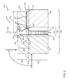
Fig. 2 , there is provided a cross-section of another exemplary embodiment of a weld set-up 200 that is made in accordance with the present invention. Like numerals are used to identify like components as betweenFigs. 1 and2 , except that the numerals have been increased by 100 (e.g., 100 is now 200 inFig. 2 ). For example, the weld set-up 200 ofFig. 2 may comprise aprimary part 202, asecondary part 204, and a weld joint 206. The weld set-up 200 may also comprise asacrificial portion 230, a workingportion 232, and apost-processing portion 234 with apost-processing machining line 236 that separates thesacrificial portion 230 from the workingportion 232. - There is also shown that the weld set-
up 200 may comprise aweld zone 238 that may incorporate portions of both theprimary piece 202 and thesecondary piece 204 such as defined by the HAZ resulting from application of thewelding beam 226. Theweld zone 238 may also comprise weld features 240 such asnailheads 242 that are formations typically associated with application of the weld beam 226 (e.g., an electron beam), and in one particular construction thenailheads 242 may comprise aprimary nailhead 244 and apreferential nailhead 246, both of which may form in response to the selected welding technique for use as thewelding beam 226. By way of non-limiting example, the welding technique may be conventional electron beam welding. - The
primary nailhead 244 and thepreferential nailhead 246 may comprise one ormore nailhead portions 248. The formation of thenailhead portions 248 is generally understood by those artisans knowledgeable in the welding arts, and thus additional details are not necessary. As discussed above, configurations of the welding pieces, some of which are illustrated inFigs. 1 and2 , may promote preferential location of thenailheads 242. This preferential location may define, in one example, the location of theprimary nailhead 244, thepreferential nailhead 246, as well as the distribution, location, and/or size of thenailhead portions 248. - Particular to the exemplary embodiment of
Fig. 2 , it is seen that the configuration of thewelding pieces secondary piece 204 of theprimary nailhead 244 with a pair ofprimary nailhead portions 250. Likewise this configuration promotes formation in theprimary piece 202 of thepreferential nailhead 246 with apreferential nailhead portion 252. The location of thepreferential nailhead portion 252 exclusively in theprimary piece 202, in combination with the lack of any complementary nailhead portion of thepreferential nailhead 246 co-located in thesecondary piece 204, is beneficial because the resulting preferential geometry effectively re-locates areas of micro-cracking to desired portions of the weld set-up 200. - To exemplify, in one embodiment of the weld set-
up 200 the preferential geometry may locate an area ofmicro-cracking 254 outside of the workingportion 232 such as in thesacrificial portion 230. Post-process techniques such as machining along thepost-processing machining line 236 may be employed to separate thesacrificial portion 230 from the workingportion 232. This separation removes the area ofmicro-cracking 254 that may effectively leave the workingportion 232, and more particularly thesecondary piece 204, free from, e.g., micro-cracks, which would normally originate at or around thepreferential nailhead 246. - Weld set-ups of the type contemplated by the weld set-
up Figs. 3 and4 and described below. For purposes of the following discussion, but by way of non-limiting examples, these welding processes may be implemented using an electron beam welding apparatus. Though not disclosed in detail herein, relevant knowledge about the design, operation, and process parameters of such electron beam welders may be readily understood by those artisans skilled in the welding arts. - Turning now to
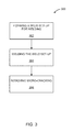
Fig. 3 , and alsoFig. 2 , there is provided an exemplary embodiment of awelding method 300 embodying concepts of the present disclosure. Thewelding method 300 may comprise, atstep 302, forming a weld set-up for welding. This weld set-up may be constructed as discussed in connection with the weld set-up 200 discussed above. Thewelding method 300 may also comprise, atstep 304, welding the weld set-up 200, which may be accomplished by imparting the electron beam onto thesecondary piece 204. Process parameters for the electron beam may be determined based on properties of theprimary piece 202 and/or thesecondary piece 204, including but not limited to material composition, thickness, depth of weld (e.g., depth of weld joint 206), among many others. Thewelding method 300 may further comprise, atstep 306, removing micro-cracking near the weld joint 206, which in one example may be achieved by removing at least theprimary nailhead 244 from thesecondary piece 204 of the weld set-up 200. - There is also provided in
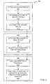
Fig. 4 an exemplary embodiment of awelding method 400. In this example, like numerals are also used to identify complimentary steps as between the methods illustrated inFigs. 3 and4 , except the numerals are increased by 100 (e.g., 300 is now 400 inFig. 4 ). By way of non-limiting example, thewelding method 400 may comprise, atstep 402, forming a weld set-up 200 for welding, atstep 404, welding the weld set-up 200, and atstep 406, performing a post-weld operation. More particular to the embodiment ofwelding method 400 ofFig. 4 , there is also providedsuch welding method 400 that comprises, atstep 408, fitting-up thesecondary piece 204 with theprimary piece 202, atstep 410, preparing thesurface secondary piece 204 and theprimary piece 202, and atstep 412, securing thesecondary piece 204 to theprimary piece 202. - Each of the steps 410-412 may be implemented in any one of a variety of ways. Fitting-up of the two pieces of the weld set-
up 200 may be accomplished by way of machining techniques that are used to form one or both of the weldedpieces secondary piece 204 is, for example, a replacement or add on part to theprimary piece 202, then machining may be used to remove any formerly attached piece from theprimary piece 202 so as to make room for thesecondary piece 204 that is to be attached thereon. These same machining techniques may be used as or in conjunction with surface preparation techniques such as deburring to prepare portions the weldedpieces surfaces pieces pieces up 200. - In view of the foregoing, embodiments of the
welding method 400 may also comprise, atstep 414, applying treatment to the weld set-up 200, and also, atstep 416, selecting parameters for thewelding beam 226. One or more of thesteps pieces pieces pieces pieces pieces up 206. - Embodiments of the
welding method 400 may further comprise additional steps such as at steps 418, applying post-welding treatment to the weld set-up 200, and atstep 420, performing post weld-operations to separate thesacrificial portion 230 and the workingportion 232. Suitable post-weld operations may comprise machining the work-piece 208 along thepost-processing machining line 236. These operations may further comprise other operations related to the welding process and/or other polishing, sanding, and deburring techniques that may be used to separate and or make useful the material of the workingportion 232. - It is contemplated that numerical values, as well as other values that are recited herein are modified by the term "about", whether expressly stated or inherently derived by the discussion of the present disclosure. As used herein, the term "about" defines the numerical boundaries of the modified values so as to include, but not be limited to, tolerances and values up to, and including the numerical value so modified. That is, numerical values may include the actual value that is expressly stated, as well as other values that are, or may be, the decimal, fractional, or other multiple of the actual value indicated, and/or described in the disclosure.
- While the present invention has been particularly shown and described with reference to an exemplary embodiment, it will be understood by one skilled in the art that various changes in detail may be effected therein without departing from the spirit and scope of the invention as defined by claims that may be supported by the written description and drawings. Further, where this exemplary embodiments (and other related derivations) are described with reference to a certain number of elements it will be understood that other exemplary embodiments may be practiced utilizing either less than or more than the certain number of elements.
Claims (15)
- An apparatus prepared for weld by an electron welding beam (226), said apparatus comprising:a first piece (202) having a surface (210) facing the electron welding beam (226); anda second piece (204) abutting the first piece (202) to form a weld joint (206), the second piece (204) including a flange (214) extending away from the weld joint (206) over the surface (210) of the first piece,wherein the first piece (202) and the second piece (204) form a work-piece that includes a sacrificial portion (230) and a working portion (232) separated from the sacrificial portion (230) by a post-processing portion (234), andwherein the sacrificial portion (230) includes the flange (214).
- An apparatus according to claim 1, wherein the flange (214) is formed monolithically with the second piece (204).
- An apparatus according to claim 1 or 2, wherein the first piece (202) and the second piece (204) comprise at least 50 % nickel, for example wherein the first piece (202) and the second piece (204) comprise about 58 % nickel, about 19 % chromium, about 13% cobalt, about 4 % molybdenum, about 3 % titanium, and about 1.4 % aluminum.
- An apparatus according to claim 1, 2 or 3, wherein the first piece (202) includes a cast material and the second piece (204) includes a forged material, and wherein each of the cast material and the forged material comprise a superalloy.
- An apparatus according to any preceding claim, wherein the post-processing portion (234) includes a post-weld machining line (236) that defines each of the sacrificial portion (230) and the working portion (232), and wherein the sacrificial portion (230) further includes at least a portion of the first piece (202).
- An apparatus according to any preceding claim, further comprising a means for clamping the first piece (202) and the second piece (204), wherein optionally the means for clamping applies a clamping force (228) that biases together the flange (214) and the surface (210) of the first piece (202).
- An apparatus according to any preceding claim, wherein the flange (214) includes an end surface (216) located a relative distance (218) from the weld joint (206), and wherein the relative distance (218) is larger than a weld zone (238) formed by the electron welding beam (226) in the flange (214), and wherein optionally the weld zone (238) includes a plurality of nailheads (242) that result from application of the electron welding beam (226) to the second piece (204), and wherein the nailheads (242) comprise a first nailhead (252) formed exclusively in the first piece (202).
- A method for reducing micro-cracks induced by an electron welding beam (226), said method comprising providing a first piece (202) having a surface (210) facing the welding beam (226); abutting a second piece (204) to the first piece (202) to form a weld joint (206), the second piece (204) including a flange (214) extending over the surface (210), wherein the first piece (202) and the second piece (204) form a work-piece that includes a sacrificial portion (230) and a working portion (232) separated from the sacrificial portion (230) by a post-processing zone (234), and wherein the second piece (204) receives the electron welding beam (226) with welding parameters that cause a first nailhead (252) to form exclusively in the first piece (202).
- A method according to claim 8, wherein the flange (214) is formed monolithically with the second piece (204).
- A method according to claim 8 or 9, further comprising clamping the first piece (202) and the second piece (204).
- A method according to claim 8, 9 or 10, further comprising performing a preweld treatment of each of the first piece (202) and the second piece (204), wherein the preweld treatment changes the material morphology of the first piece (202) and the second piece (204).
- A method according to any of claims 8 to 11, further comprising separating the sacrificial portion (230) from the working portion (232) along a post-processing machining line (236), wherein the post-processing machining line (236) defines each of the sacrificial portion (230) and the working portion (232), and wherein the sacrificial portion (230) further includes a portion of the first nailhead (244).
- A method according to any of claims 8 to 12, wherein the first piece (202) and the second piece (204) comprise a superalloy have at least about 50 % nickel, for example wherein the superalloy includes about 19 % chromium, about 13% cobalt, about 4 % molybdenum, about 3 % titanium, and about 1.4 % aluminum, wherein optionally the first piece (202) is formed by casting, and wherein the second piece (204) is formed by forging.
- A method according to any of claims 8 to 13, wherein the welding parameters cause a second nailhead (246) to form proximate the flange (214).
- A method according to any of claims 8 to 14, further comprising heating the work-piece after formation of the first nailhead (244).
Applications Claiming Priority (1)
| Application Number | Priority Date | Filing Date | Title |
|---|---|---|---|
| US12/720,370 US8304093B2 (en) | 2010-03-09 | 2010-03-09 | Apparatus and method for preferential formation of weld joint |
Publications (2)
| Publication Number | Publication Date |
|---|---|
| EP2364808A1 true EP2364808A1 (en) | 2011-09-14 |
| EP2364808B1 EP2364808B1 (en) | 2015-04-22 |
Family
ID=44201087
Family Applications (1)
| Application Number | Title | Priority Date | Filing Date |
|---|---|---|---|
| EP20110157514 Active EP2364808B1 (en) | 2010-03-09 | 2011-03-09 | Method for preferential formation of weld join |
Country Status (2)
| Country | Link |
|---|---|
| US (1) | US8304093B2 (en) |
| EP (1) | EP2364808B1 (en) |
Families Citing this family (2)
| Publication number | Priority date | Publication date | Assignee | Title |
|---|---|---|---|---|
| US20130266818A1 (en) | 2012-04-10 | 2013-10-10 | Hamilton Sundstrand Corporation | Article including a weld joint |
| CN112958899B (en) * | 2021-03-17 | 2022-11-29 | 中国航发动力股份有限公司 | Method for eliminating shrinkage cavity defect at root of electron beam welding seam |
Citations (4)
| Publication number | Priority date | Publication date | Assignee | Title |
|---|---|---|---|---|
| US4063062A (en) * | 1974-10-28 | 1977-12-13 | Bbc Brown Boveri & Company Limited | Electron beam welding technique for joining two workpieces together |
| WO1982002352A1 (en) * | 1981-01-02 | 1982-07-22 | Sciaky Bros | Method for electron beam welding |
| FR2584004A1 (en) * | 1985-06-26 | 1987-01-02 | Mitsubishi Heavy Ind Ltd | ELECTRON BEAM WELDING METHOD FOR PERFORATED CYLINDER OF PAPER MACHINE |
| EP1820597A2 (en) * | 2006-02-15 | 2007-08-22 | General Electric Company | Methods and apparatus for welding turbine engine rotors |
Family Cites Families (14)
| Publication number | Priority date | Publication date | Assignee | Title |
|---|---|---|---|---|
| US4850802A (en) * | 1983-04-21 | 1989-07-25 | Allied-Signal Inc. | Composite compressor wheel for turbochargers |
| DE3738492A1 (en) * | 1987-11-12 | 1989-05-24 | Wagner Maschf Gustav | METHOD FOR FASTENING HSS CUTTERS OR THE LIKE ON A TOOL CARRIER AND TOOLS PRODUCED BY THIS PROCESS |
| US4903888A (en) * | 1988-05-05 | 1990-02-27 | Westinghouse Electric Corp. | Turbine system having more failure resistant rotors and repair welding of low alloy ferrous turbine components by controlled weld build-up |
| GB9205178D0 (en) * | 1992-03-10 | 1992-04-22 | Otter Controls Ltd | Improvements relating to controls for electrically heated water boiling vessels |
| DE69302219T2 (en) * | 1992-06-05 | 1996-09-19 | Gec Alsthom Electromec | Process for applying protective coating inserts to objects made of martensitic steel or titanium alloys |
| US5351395A (en) * | 1992-12-30 | 1994-10-04 | General Electric Company | Process for producing turbine bucket with water droplet erosion protection |
| GB9522332D0 (en) * | 1995-11-01 | 1996-01-03 | Biocompatibles Ltd | Braided stent |
| US6568077B1 (en) * | 2000-05-11 | 2003-05-27 | General Electric Company | Blisk weld repair |
| JP3883103B2 (en) * | 2001-08-06 | 2007-02-21 | 兼房株式会社 | Finger cutter |
| US6838190B2 (en) * | 2001-12-20 | 2005-01-04 | General Electric Company | Article with intermediate layer and protective layer, and its fabrication |
| DE102004032461A1 (en) * | 2004-06-30 | 2006-02-02 | Rolls-Royce Deutschland Ltd & Co Kg | Process and repair blade part for BLISK repair or BLISKs new production |
| US20070045260A1 (en) * | 2005-08-30 | 2007-03-01 | Frank Feng | Welded aluminum sheets and process therefore |
| JP2008018436A (en) * | 2006-07-11 | 2008-01-31 | Yorozu Corp | Welding method and weldment |
| SG143087A1 (en) * | 2006-11-21 | 2008-06-27 | Turbine Overhaul Services Pte | Laser fillet welding |
-
2010
- 2010-03-09 US US12/720,370 patent/US8304093B2/en active Active
-
2011
- 2011-03-09 EP EP20110157514 patent/EP2364808B1/en active Active
Patent Citations (4)
| Publication number | Priority date | Publication date | Assignee | Title |
|---|---|---|---|---|
| US4063062A (en) * | 1974-10-28 | 1977-12-13 | Bbc Brown Boveri & Company Limited | Electron beam welding technique for joining two workpieces together |
| WO1982002352A1 (en) * | 1981-01-02 | 1982-07-22 | Sciaky Bros | Method for electron beam welding |
| FR2584004A1 (en) * | 1985-06-26 | 1987-01-02 | Mitsubishi Heavy Ind Ltd | ELECTRON BEAM WELDING METHOD FOR PERFORATED CYLINDER OF PAPER MACHINE |
| EP1820597A2 (en) * | 2006-02-15 | 2007-08-22 | General Electric Company | Methods and apparatus for welding turbine engine rotors |
Also Published As
| Publication number | Publication date |
|---|---|
| US20110220622A1 (en) | 2011-09-15 |
| US8304093B2 (en) | 2012-11-06 |
| EP2364808B1 (en) | 2015-04-22 |
Similar Documents
| Publication | Publication Date | Title |
|---|---|---|
| JP4573108B2 (en) | Welding method | |
| EP1916051B1 (en) | Method of repairing an aperture and defect in a part with welding using an insert with top and runoff plates and backing | |
| US20070084906A1 (en) | Hole repair technique and apparatus | |
| JP2009018345A (en) | Welding repair method for turbine bucket tip | |
| US2615236A (en) | Blade edge welding technique | |
| EP3034229B1 (en) | Weld filler for superalloys | |
| US9085042B2 (en) | Stud welding repair of superalloy components | |
| US8304093B2 (en) | Apparatus and method for preferential formation of weld joint | |
| CN109202268A (en) | Linear friction welding method, aircraft grid beam welding method and its equipment | |
| KR101276334B1 (en) | Method For Welding Aluminium Alloy and Titanium Alloy By Hybrid Friction Stir Welding with Tungsten Inert Gas Welding | |
| CN108788432B (en) | A kind of aviation same IC10 single crystal superalloy welding method | |
| JP6037018B2 (en) | Resistance spot welding method | |
| US9227267B1 (en) | Warm bond method for butt joining metal parts | |
| EP1512482A1 (en) | Method for Improved weld penetration by means of the formation of a surface oxide layer, and the resulting article. | |
| JP2021020243A (en) | Welding method of box type steel structure | |
| JP2007021530A (en) | Welding repair method for cast steel products and cast steel products having weld repair parts | |
| JP2012030237A (en) | Welded joint structure of structural member and welding method used for the same | |
| KR102046957B1 (en) | High Efficient Welded Joint Having Excellent Brittle Crack Propagation Stopping Performance and Method for Manufacturing the Same | |
| US9333589B2 (en) | Component and method for joining metal elements | |
| JPH0191993A (en) | Crack repairing method for steel structure under stress fluctuation | |
| JPH071143A (en) | Method of welding aluminum or aluminum alloy article | |
| Petley et al. | Weld ductility evaluation of aeroengine materials by performing bend tests | |
| JP6811063B2 (en) | Resistance spot welding method and resistance spot welding joint manufacturing method | |
| CN116586725A (en) | A Welding Method for Large Weld Seam of Low Temperature Cast Steel and Low Alloy Steel | |
| CN117260185A (en) | Manufacturing method of titanium alloy framework |
Legal Events
| Date | Code | Title | Description |
|---|---|---|---|
| PUAI | Public reference made under article 153(3) epc to a published international application that has entered the european phase |
Free format text: ORIGINAL CODE: 0009012 |
|
| AK | Designated contracting states |
Kind code of ref document: A1 Designated state(s): AL AT BE BG CH CY CZ DE DK EE ES FI FR GB GR HR HU IE IS IT LI LT LU LV MC MK MT NL NO PL PT RO RS SE SI SK SM TR |
|
| AX | Request for extension of the european patent |
Extension state: BA ME |
|
| 17P | Request for examination filed |
Effective date: 20120314 |
|
| 17Q | First examination report despatched |
Effective date: 20131015 |
|
| GRAP | Despatch of communication of intention to grant a patent |
Free format text: ORIGINAL CODE: EPIDOSNIGR1 |
|
| INTG | Intention to grant announced |
Effective date: 20140918 |
|
| GRAS | Grant fee paid |
Free format text: ORIGINAL CODE: EPIDOSNIGR3 |
|
| GRAA | (expected) grant |
Free format text: ORIGINAL CODE: 0009210 |
|
| AK | Designated contracting states |
Kind code of ref document: B1 Designated state(s): AL AT BE BG CH CY CZ DE DK EE ES FI FR GB GR HR HU IE IS IT LI LT LU LV MC MK MT NL NO PL PT RO RS SE SI SK SM TR |
|
| REG | Reference to a national code |
Ref country code: GB Ref legal event code: FG4D |
|
| REG | Reference to a national code |
Ref country code: CH Ref legal event code: EP |
|
| REG | Reference to a national code |
Ref country code: AT Ref legal event code: REF Ref document number: 722915 Country of ref document: AT Kind code of ref document: T Effective date: 20150515 |
|
| REG | Reference to a national code |
Ref country code: IE Ref legal event code: FG4D |
|
| REG | Reference to a national code |
Ref country code: DE Ref legal event code: R096 Ref document number: 602011015812 Country of ref document: DE Effective date: 20150603 |
|
| REG | Reference to a national code |
Ref country code: NL Ref legal event code: VDEP Effective date: 20150422 |
|
| REG | Reference to a national code |
Ref country code: AT Ref legal event code: MK05 Ref document number: 722915 Country of ref document: AT Kind code of ref document: T Effective date: 20150422 |
|
| REG | Reference to a national code |
Ref country code: LT Ref legal event code: MG4D |
|
| PG25 | Lapsed in a contracting state [announced via postgrant information from national office to epo] |
Ref country code: NL Free format text: LAPSE BECAUSE OF FAILURE TO SUBMIT A TRANSLATION OF THE DESCRIPTION OR TO PAY THE FEE WITHIN THE PRESCRIBED TIME-LIMIT Effective date: 20150422 |
|
| PG25 | Lapsed in a contracting state [announced via postgrant information from national office to epo] |
Ref country code: PT Free format text: LAPSE BECAUSE OF FAILURE TO SUBMIT A TRANSLATION OF THE DESCRIPTION OR TO PAY THE FEE WITHIN THE PRESCRIBED TIME-LIMIT Effective date: 20150824 Ref country code: FI Free format text: LAPSE BECAUSE OF FAILURE TO SUBMIT A TRANSLATION OF THE DESCRIPTION OR TO PAY THE FEE WITHIN THE PRESCRIBED TIME-LIMIT Effective date: 20150422 Ref country code: ES Free format text: LAPSE BECAUSE OF FAILURE TO SUBMIT A TRANSLATION OF THE DESCRIPTION OR TO PAY THE FEE WITHIN THE PRESCRIBED TIME-LIMIT Effective date: 20150422 Ref country code: HR Free format text: LAPSE BECAUSE OF FAILURE TO SUBMIT A TRANSLATION OF THE DESCRIPTION OR TO PAY THE FEE WITHIN THE PRESCRIBED TIME-LIMIT Effective date: 20150422 Ref country code: LT Free format text: LAPSE BECAUSE OF FAILURE TO SUBMIT A TRANSLATION OF THE DESCRIPTION OR TO PAY THE FEE WITHIN THE PRESCRIBED TIME-LIMIT Effective date: 20150422 Ref country code: NO Free format text: LAPSE BECAUSE OF FAILURE TO SUBMIT A TRANSLATION OF THE DESCRIPTION OR TO PAY THE FEE WITHIN THE PRESCRIBED TIME-LIMIT Effective date: 20150722 |
|
| PG25 | Lapsed in a contracting state [announced via postgrant information from national office to epo] |
Ref country code: RS Free format text: LAPSE BECAUSE OF FAILURE TO SUBMIT A TRANSLATION OF THE DESCRIPTION OR TO PAY THE FEE WITHIN THE PRESCRIBED TIME-LIMIT Effective date: 20150422 Ref country code: LV Free format text: LAPSE BECAUSE OF FAILURE TO SUBMIT A TRANSLATION OF THE DESCRIPTION OR TO PAY THE FEE WITHIN THE PRESCRIBED TIME-LIMIT Effective date: 20150422 Ref country code: GR Free format text: LAPSE BECAUSE OF FAILURE TO SUBMIT A TRANSLATION OF THE DESCRIPTION OR TO PAY THE FEE WITHIN THE PRESCRIBED TIME-LIMIT Effective date: 20150723 Ref country code: AT Free format text: LAPSE BECAUSE OF FAILURE TO SUBMIT A TRANSLATION OF THE DESCRIPTION OR TO PAY THE FEE WITHIN THE PRESCRIBED TIME-LIMIT Effective date: 20150422 Ref country code: IS Free format text: LAPSE BECAUSE OF FAILURE TO SUBMIT A TRANSLATION OF THE DESCRIPTION OR TO PAY THE FEE WITHIN THE PRESCRIBED TIME-LIMIT Effective date: 20150822 |
|
| REG | Reference to a national code |
Ref country code: DE Ref legal event code: R097 Ref document number: 602011015812 Country of ref document: DE |
|
| PG25 | Lapsed in a contracting state [announced via postgrant information from national office to epo] |
Ref country code: DK Free format text: LAPSE BECAUSE OF FAILURE TO SUBMIT A TRANSLATION OF THE DESCRIPTION OR TO PAY THE FEE WITHIN THE PRESCRIBED TIME-LIMIT Effective date: 20150422 Ref country code: EE Free format text: LAPSE BECAUSE OF FAILURE TO SUBMIT A TRANSLATION OF THE DESCRIPTION OR TO PAY THE FEE WITHIN THE PRESCRIBED TIME-LIMIT Effective date: 20150422 |
|
| PLBE | No opposition filed within time limit |
Free format text: ORIGINAL CODE: 0009261 |
|
| STAA | Information on the status of an ep patent application or granted ep patent |
Free format text: STATUS: NO OPPOSITION FILED WITHIN TIME LIMIT |
|
| PG25 | Lapsed in a contracting state [announced via postgrant information from national office to epo] |
Ref country code: PL Free format text: LAPSE BECAUSE OF FAILURE TO SUBMIT A TRANSLATION OF THE DESCRIPTION OR TO PAY THE FEE WITHIN THE PRESCRIBED TIME-LIMIT Effective date: 20150422 Ref country code: RO Free format text: LAPSE BECAUSE OF NON-PAYMENT OF DUE FEES Effective date: 20150422 Ref country code: CZ Free format text: LAPSE BECAUSE OF FAILURE TO SUBMIT A TRANSLATION OF THE DESCRIPTION OR TO PAY THE FEE WITHIN THE PRESCRIBED TIME-LIMIT Effective date: 20150422 Ref country code: SK Free format text: LAPSE BECAUSE OF FAILURE TO SUBMIT A TRANSLATION OF THE DESCRIPTION OR TO PAY THE FEE WITHIN THE PRESCRIBED TIME-LIMIT Effective date: 20150422 |
|
| 26N | No opposition filed |
Effective date: 20160125 |
|
| PG25 | Lapsed in a contracting state [announced via postgrant information from national office to epo] |
Ref country code: IT Free format text: LAPSE BECAUSE OF FAILURE TO SUBMIT A TRANSLATION OF THE DESCRIPTION OR TO PAY THE FEE WITHIN THE PRESCRIBED TIME-LIMIT Effective date: 20150422 |
|
| PG25 | Lapsed in a contracting state [announced via postgrant information from national office to epo] |
Ref country code: SI Free format text: LAPSE BECAUSE OF FAILURE TO SUBMIT A TRANSLATION OF THE DESCRIPTION OR TO PAY THE FEE WITHIN THE PRESCRIBED TIME-LIMIT Effective date: 20150422 |
|
| PG25 | Lapsed in a contracting state [announced via postgrant information from national office to epo] |
Ref country code: BE Free format text: LAPSE BECAUSE OF FAILURE TO SUBMIT A TRANSLATION OF THE DESCRIPTION OR TO PAY THE FEE WITHIN THE PRESCRIBED TIME-LIMIT Effective date: 20150422 |
|
| PG25 | Lapsed in a contracting state [announced via postgrant information from national office to epo] |
Ref country code: MC Free format text: LAPSE BECAUSE OF FAILURE TO SUBMIT A TRANSLATION OF THE DESCRIPTION OR TO PAY THE FEE WITHIN THE PRESCRIBED TIME-LIMIT Effective date: 20150422 Ref country code: LU Free format text: LAPSE BECAUSE OF FAILURE TO SUBMIT A TRANSLATION OF THE DESCRIPTION OR TO PAY THE FEE WITHIN THE PRESCRIBED TIME-LIMIT Effective date: 20160309 |
|
| REG | Reference to a national code |
Ref country code: CH Ref legal event code: PL |
|
| REG | Reference to a national code |
Ref country code: IE Ref legal event code: MM4A |
|
| REG | Reference to a national code |
Ref country code: FR Ref legal event code: ST Effective date: 20161130 |
|
| PG25 | Lapsed in a contracting state [announced via postgrant information from national office to epo] |
Ref country code: FR Free format text: LAPSE BECAUSE OF NON-PAYMENT OF DUE FEES Effective date: 20160331 Ref country code: CH Free format text: LAPSE BECAUSE OF NON-PAYMENT OF DUE FEES Effective date: 20160331 Ref country code: IE Free format text: LAPSE BECAUSE OF NON-PAYMENT OF DUE FEES Effective date: 20160309 Ref country code: LI Free format text: LAPSE BECAUSE OF NON-PAYMENT OF DUE FEES Effective date: 20160331 |
|
| PG25 | Lapsed in a contracting state [announced via postgrant information from national office to epo] |
Ref country code: SE Free format text: LAPSE BECAUSE OF FAILURE TO SUBMIT A TRANSLATION OF THE DESCRIPTION OR TO PAY THE FEE WITHIN THE PRESCRIBED TIME-LIMIT Effective date: 20150422 |
|
| REG | Reference to a national code |
Ref country code: DE Ref legal event code: R082 Ref document number: 602011015812 Country of ref document: DE Representative=s name: SCHMITT-NILSON SCHRAUD WAIBEL WOHLFROM PATENTA, DE |
|
| REG | Reference to a national code |
Ref country code: DE Ref legal event code: R082 Ref document number: 602011015812 Country of ref document: DE Representative=s name: SCHMITT-NILSON SCHRAUD WAIBEL WOHLFROM PATENTA, DE Ref country code: DE Ref legal event code: R081 Ref document number: 602011015812 Country of ref document: DE Owner name: UNITED TECHNOLOGIES CORP. (N.D.GES.D. STAATES , US Free format text: FORMER OWNER: UNITED TECHNOLOGIES CORPORATION, HARTFORD, CONN., US |
|
| PG25 | Lapsed in a contracting state [announced via postgrant information from national office to epo] |
Ref country code: MT Free format text: LAPSE BECAUSE OF FAILURE TO SUBMIT A TRANSLATION OF THE DESCRIPTION OR TO PAY THE FEE WITHIN THE PRESCRIBED TIME-LIMIT Effective date: 20150422 |
|
| PG25 | Lapsed in a contracting state [announced via postgrant information from national office to epo] |
Ref country code: SM Free format text: LAPSE BECAUSE OF FAILURE TO SUBMIT A TRANSLATION OF THE DESCRIPTION OR TO PAY THE FEE WITHIN THE PRESCRIBED TIME-LIMIT Effective date: 20150422 Ref country code: CY Free format text: LAPSE BECAUSE OF FAILURE TO SUBMIT A TRANSLATION OF THE DESCRIPTION OR TO PAY THE FEE WITHIN THE PRESCRIBED TIME-LIMIT Effective date: 20150422 Ref country code: HU Free format text: LAPSE BECAUSE OF FAILURE TO SUBMIT A TRANSLATION OF THE DESCRIPTION OR TO PAY THE FEE WITHIN THE PRESCRIBED TIME-LIMIT; INVALID AB INITIO Effective date: 20110309 |
|
| PG25 | Lapsed in a contracting state [announced via postgrant information from national office to epo] |
Ref country code: MT Free format text: LAPSE BECAUSE OF FAILURE TO SUBMIT A TRANSLATION OF THE DESCRIPTION OR TO PAY THE FEE WITHIN THE PRESCRIBED TIME-LIMIT Effective date: 20160331 Ref country code: TR Free format text: LAPSE BECAUSE OF FAILURE TO SUBMIT A TRANSLATION OF THE DESCRIPTION OR TO PAY THE FEE WITHIN THE PRESCRIBED TIME-LIMIT Effective date: 20150422 Ref country code: MK Free format text: LAPSE BECAUSE OF FAILURE TO SUBMIT A TRANSLATION OF THE DESCRIPTION OR TO PAY THE FEE WITHIN THE PRESCRIBED TIME-LIMIT Effective date: 20150422 |
|
| PG25 | Lapsed in a contracting state [announced via postgrant information from national office to epo] |
Ref country code: BG Free format text: LAPSE BECAUSE OF FAILURE TO SUBMIT A TRANSLATION OF THE DESCRIPTION OR TO PAY THE FEE WITHIN THE PRESCRIBED TIME-LIMIT Effective date: 20150422 |
|
| PG25 | Lapsed in a contracting state [announced via postgrant information from national office to epo] |
Ref country code: AL Free format text: LAPSE BECAUSE OF FAILURE TO SUBMIT A TRANSLATION OF THE DESCRIPTION OR TO PAY THE FEE WITHIN THE PRESCRIBED TIME-LIMIT Effective date: 20150422 |
|
| REG | Reference to a national code |
Ref country code: DE Ref legal event code: R081 Ref document number: 602011015812 Country of ref document: DE Owner name: RAYTHEON TECHNOLOGIES CORPORATION (N.D.GES.D.S, US Free format text: FORMER OWNER: UNITED TECHNOLOGIES CORP. (N.D.GES.D. STAATES DELAWARE), FARMINGTON, CONN., US Ref country code: DE Ref legal event code: R081 Ref document number: 602011015812 Country of ref document: DE Owner name: RTX CORPORATION (N.D.GES.D. STAATES DELAWARE),, US Free format text: FORMER OWNER: UNITED TECHNOLOGIES CORP. (N.D.GES.D. STAATES DELAWARE), FARMINGTON, CONN., US |
|
| P01 | Opt-out of the competence of the unified patent court (upc) registered |
Effective date: 20230519 |
|
| REG | Reference to a national code |
Ref country code: DE Ref legal event code: R081 Ref document number: 602011015812 Country of ref document: DE Owner name: RTX CORPORATION (N.D.GES.D. STAATES DELAWARE),, US Free format text: FORMER OWNER: RAYTHEON TECHNOLOGIES CORPORATION (N.D.GES.D.STAATES DELAWARE), ARLINGTON, VA, US |
|
| PGFP | Annual fee paid to national office [announced via postgrant information from national office to epo] |
Ref country code: GB Payment date: 20260219 Year of fee payment: 16 |
|
| PGFP | Annual fee paid to national office [announced via postgrant information from national office to epo] |
Ref country code: DE Payment date: 20260219 Year of fee payment: 16 |