EP2364008B1 - Method to assign a customer premises equipment to a subscriber's data record, demarcation point unit, and network element - Google Patents
Method to assign a customer premises equipment to a subscriber's data record, demarcation point unit, and network element Download PDFInfo
- Publication number
- EP2364008B1 EP2364008B1 EP10305195A EP10305195A EP2364008B1 EP 2364008 B1 EP2364008 B1 EP 2364008B1 EP 10305195 A EP10305195 A EP 10305195A EP 10305195 A EP10305195 A EP 10305195A EP 2364008 B1 EP2364008 B1 EP 2364008B1
- Authority
- EP
- European Patent Office
- Prior art keywords
- ontn
- customer premises
- demarcation point
- premises equipment
- dpun
- Prior art date
- Legal status (The legal status is an assumption and is not a legal conclusion. Google has not performed a legal analysis and makes no representation as to the accuracy of the status listed.)
- Active
Links
- 238000000034 method Methods 0.000 title claims abstract description 11
- 230000003287 optical effect Effects 0.000 description 35
- 230000005540 biological transmission Effects 0.000 description 2
- 238000006243 chemical reaction Methods 0.000 description 2
- 230000008878 coupling Effects 0.000 description 2
- 238000010168 coupling process Methods 0.000 description 2
- 238000005859 coupling reaction Methods 0.000 description 2
- 238000010586 diagram Methods 0.000 description 1
- 238000012544 monitoring process Methods 0.000 description 1
Images

Classifications
-
- H—ELECTRICITY
- H04—ELECTRIC COMMUNICATION TECHNIQUE
- H04M—TELEPHONIC COMMUNICATION
- H04M3/00—Automatic or semi-automatic exchanges
- H04M3/22—Arrangements for supervision, monitoring or testing
- H04M3/229—Wire identification arrangements; Number assignment determination
-
- H—ELECTRICITY
- H04—ELECTRIC COMMUNICATION TECHNIQUE
- H04M—TELEPHONIC COMMUNICATION
- H04M3/00—Automatic or semi-automatic exchanges
- H04M3/02—Calling substations, e.g. by ringing
-
- H—ELECTRICITY
- H04—ELECTRIC COMMUNICATION TECHNIQUE
- H04M—TELEPHONIC COMMUNICATION
- H04M11/00—Telephonic communication systems specially adapted for combination with other electrical systems
- H04M11/06—Simultaneous speech and data transmission, e.g. telegraphic transmission over the same conductors
-
- H—ELECTRICITY
- H04—ELECTRIC COMMUNICATION TECHNIQUE
- H04M—TELEPHONIC COMMUNICATION
- H04M9/00—Arrangements for interconnection not involving centralised switching
-
- H—ELECTRICITY
- H04—ELECTRIC COMMUNICATION TECHNIQUE
- H04B—TRANSMISSION
- H04B2210/00—Indexing scheme relating to optical transmission systems
- H04B2210/07—Monitoring an optical transmission system using a supervisory signal
- H04B2210/074—Monitoring an optical transmission system using a supervisory signal using a superposed, over-modulated signal
Definitions
- the invention relates to a method to assign a customer premises equipment to a subscriber's data record according to the preamble of claim 1, to a demarcation point unit according to the preamble of claim 4, and to a network element for a central office, according to the preamble of claim 5.
- Such telecommunication's networks are well known, for example from EP 1 986 351 A1 , and EP 2 015 480 A1 .
- Both, optical and wireless access networks normally are point-to-multipoint networks.
- Each customer has a connection point, where he or she can connect whatever customer premises equipment like simple telephones, servers, or multimedia devices. Such connecting equipment is being done by the customer himself or herself and can also be changed at whatever time. There is a need to register the used equipment in the central office of the network operator and to unambiguously assign it to a subscriber's data record.
- the invention deals with the problem of providing a method and respective devices to assign a customer premises equipment to a subscriber's data record registered in the central office of the network operator.
- the invention makes use of two circumstances:
- any customer premises equipment foreseen for connecting two an optical access line nowadays is built such that, when in operation, it regularly reports the received signal amplitude to the central office, to which it is connected.
- the chronological sequence of the imposing of the identifier has to be adapted to the reporting intervals of the customer's device.
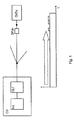
- Figure 1 shows both, a telecommunication's network, and a diagram representing the signal flow therein.
- the telecommunication's network includes a central office CO, an access network, not labeled, a demarcation point unit DPUn representing one of a multiple of network terminating units, and an optical network termination unit ONTn representing a subscriber's customer premises equipment.
- the central office CO here is shown as including an optical line termination unit OLT and a network analyser NA.
- the optical line termination unit OLT performs the conversion between optical and electrical part and the transmission technological functions like adapting power levels.
- the network analyzer NA performs some kind of network operation tasks.
- the network analyzer NA as mentioned above often is spatially separated from the optical line termination unit OLT and then mostly is a network element in common to more than one optical line termination unit OLT. This does not influence the idea of the invention.
- the signal flow represented thereunder is a signal flow from the optical line termination unit OLT within the central office CO to the optical network termination unit ONTn. From the demarcation point unit DPUn on additional signal elements are added imposed by the demarcation point unit DPUn.
- This signal flow representation is by no means to scale :
- the duration of either of the imposed signal elements has nothing to do with the propagation time it undergoes.
- the clock of the signal from the optical line termination unit OLT is such high in relation to the clock of the imposed signal elements from the demarcation point unit DPUn, that it is not even represented.
- the relation between the amplitude of the signal from the optical line termination unit OLT to the imposed signal elements from the demarcation point unit DPUn is small, namely in the range of some few percents, not more than 20% but rather in the range of 5%.
- the attenuation of the signal its way from the optical line termination unit OLT to the optical network termination unit ONTn is not represented either.
- the additional signal elements imposed by the demarcation point unit DPUn represent the unambiguous and individual identifier assigned to exactly this demarcation point unit DPUh. It thus represents a digital signature proper to this demarcation point unit DPUn.
- the amplitude of these additional signal elements on the one hand has to be chosen such that it can be clearly detected by a transceiver parameter monitor allegedly being part of the network termination unit ONTn. On the other hand this amplitude is to be kept such low that the regular data flow between the optical line termination unit OLT and the optical network termination unit ONTn is not disturbed.
- Increasing the overall signal amplitude requires an optical signal source like a laser or a light emitting diode. Reducing the overall signal amplitude requires some kind of a switchable attenuator like a coupler with a coupling factor that can be influenced or either of the terminations of which can be switched.
- the clock with which such signature is to be imposed onto the signal flow has to be such low, that it is ensured that the transceiver parameter monitor in the optical network termination unit ONTn while performing its monitoring and reporting task for sure also monitors and reports the variations recognized.
- This clock therefor has to be adapted to the reporting intervals of such transceiver parameter monitor such that the reporting intervals are not shorter than one bit of the signature imposed.
- FIG. 2 shows an example of such demarcation point unit DPUn according to the invention.
- the optical line between the central office CO and the network termination unit ONTn within the subscriber's customer premises equipment is looped through through this demarcation point unit DPUn, shown as draw through line.
- the demarcation point unit DPUn further includes a control element, here designated as uP, a usual abbreviation of a microprocessor, an optical transmitter Tx, and an optical coupler coupling the optical transmitter Tx to the looped through optical line.
- microprocessor uP as control element is justified by other tasks such demarcation point unit DPUn normally is to perform. To this end it might also be coupled to the looped through optical line with receiving means for receiving data from either of both directions or with means for also transmitting towards the central office.
- the invention works, when the demarcation point unit DPUn continuously imposes its signature on the signal flow.
- the imposing the signature could be limited to short periods at the beginning of communications or on demand from the central office.
- Figure 3 shows a central office CO including a network analyzer NA as an example of a network element according to the invention.
- central office CO here is shown as including an optical line termination unit OLT and network analyzer NA.
- the optical line termination unit OLT performs the conversion between optical and electrical part and the transmission technological functions like adapting power levels.
- the network analyzer NA performs some kind of network operation tasks.
- the optical line termination unit OLT needs not to vary from known such optical line termination units. There is only a need to adapt the network analyzer NA in the central office, such that from the parameters reported from the customer premises' equipment, especially the received power levels, the signature of the assigned known demarcation point unit DPUn can be derived and whereby the customer premises equipment can be assigned to the respective subscriber's data record.
- the network analyser NA as mentioned above often is spatially separated from the optical line termination unit OLT and then mostly is a network element in common to more than one optical line termination unit OLT and more than one central office.
Abstract
Description
- The invention relates to a method to assign a customer premises equipment to a subscriber's data record according to the preamble of claim 1, to a demarcation point unit according to the preamble of claim 4, and to a network element for a central office, according to the preamble of claim 5.
- Such telecommunication's networks are well known, for example from
EP 1 986 351 A1 , andEP 2 015 480 A1 . - Both, optical and wireless access networks normally are point-to-multipoint networks. Each customer has a connection point, where he or she can connect whatever customer premises equipment like simple telephones, servers, or multimedia devices. Such connecting equipment is being done by the customer himself or herself and can also be changed at whatever time. There is a need to register the used equipment in the central office of the network operator and to unambiguously assign it to a subscriber's data record.
- To this end it is known that the customer performs a certain procedure, in the course of which a code received from the operator is to be entered. Such registration procedure is time consuming, cumbersome and error-prone.
- The invention deals with the problem of providing a method and respective devices to assign a customer premises equipment to a subscriber's data record registered in the central office of the network operator.
- This problem according to the invention is solved by a method according to the teaching of claim 1, by a network terminating unit according to the teaching of claim 4, and by a network element for a central office, according to the teaching of claim 5.
- The invention makes use of two circumstances:
- On the one hand network operators often insist on terminating their network with each customer by a device being separated from any customer's devices and being in their own responsibility. It is known also that such units, then called demarcation point units, also are assigned unambiguous and individual identifiers. Such demarcation point units are installed under the responsibility of the network operator, who thus knows the customer in whose location such demarcation point unit is installed. The classical network terminating elements called Network Termination thus is separated into two parts. One part, the Optical Network Termination, physically is terminating the network, but is in the responsibility of the subscriber; the other part, the Demarcation Point Unit, is terminating the responsibility of the operator.
- On the other hand any customer premises equipment foreseen for connecting two an optical access line nowadays is built such that, when in operation, it regularly reports the received signal amplitude to the central office, to which it is connected.
- The inventors' idea now to impose the demarcation point unit's identifier the signal coming from the central office to the customer's device by influencing the signal amplitude of this signal and have it reported to the central office. Of course the chronological sequence of the imposing of the identifier has to be adapted to the reporting intervals of the customer's device.
- Further embodiments of the invention can be found in the subclaims and in the accompanying description.
- In the following the invention will be described with reference to the accompanying drawling, in which
- Figure 1
- shows a telecommunication's network, in which a method according to the invention can be performed.
- Figure 2
- shows a demarcation point unit according to the invention.
- Figure 3
- shows a central office including a network analyser as an example of a network element according to the invention.
-
Figure 1 shows both, a telecommunication's network, and a diagram representing the signal flow therein. - The telecommunication's network includes a central office CO, an access network, not labeled, a demarcation point unit DPUn representing one of a multiple of network terminating units, and an optical network termination unit ONTn representing a subscriber's customer premises equipment.
- The central office CO here is shown as including an optical line termination unit OLT and a network analyser NA.
- The optical line termination unit OLT performs the conversion between optical and electrical part and the transmission technological functions like adapting power levels.
- The network analyzer NA performs some kind of network operation tasks.
- It is to be noticed, that in practical realization the network analyzer NA as mentioned above often is spatially separated from the optical line termination unit OLT and then mostly is a network element in common to more than one optical line termination unit OLT. This does not influence the idea of the invention.
- The signal flow represented thereunder is a signal flow from the optical line termination unit OLT within the central office CO to the optical network termination unit ONTn. From the demarcation point unit DPUn on additional signal elements are added imposed by the demarcation point unit DPUn.
- This signal flow representation is by no means to scale : The duration of either of the imposed signal elements has nothing to do with the propagation time it undergoes. The clock of the signal from the optical line termination unit OLT is such high in relation to the clock of the imposed signal elements from the demarcation point unit DPUn, that it is not even represented. The relation between the amplitude of the signal from the optical line termination unit OLT to the imposed signal elements from the demarcation point unit DPUn is small, namely in the range of some few percents, not more than 20% but rather in the range of 5%. The attenuation of the signal its way from the optical line termination unit OLT to the optical network termination unit ONTn is not represented either.
- The additional signal elements imposed by the demarcation point unit DPUn represent the unambiguous and individual identifier assigned to exactly this demarcation point unit DPUh. It thus represents a digital signature proper to this demarcation point unit DPUn.
- The amplitude of these additional signal elements on the one hand has to be chosen such that it can be clearly detected by a transceiver parameter monitor allegedly being part of the network termination unit ONTn. On the other hand this amplitude is to be kept such low that the regular data flow between the optical line termination unit OLT and the optical network termination unit ONTn is not disturbed.
- The same considerations concerning the relation between the amplitude of the signal from the optical line termination unit OLT and the imposed signal elements from the demarcation point unit DPUn apply when the signal elements from the demarcation point unit DPUn are imposed by attenuating the signal from the optical line termination unit OLT within the demarcation point unit DPUn.
- Increasing the overall signal amplitude requires an optical signal source like a laser or a light emitting diode. Reducing the overall signal amplitude requires some kind of a switchable attenuator like a coupler with a coupling factor that can be influenced or either of the terminations of which can be switched.
- The clock with which such signature is to be imposed onto the signal flow has to be such low, that it is ensured that the transceiver parameter monitor in the optical network termination unit ONTn while performing its monitoring and reporting task for sure also monitors and reports the variations recognized. This clock therefor has to be adapted to the reporting intervals of such transceiver parameter monitor such that the reporting intervals are not shorter than one bit of the signature imposed.
-
Figure 2 shows an example of such demarcation point unit DPUn according to the invention. The optical line between the central office CO and the network termination unit ONTn within the subscriber's customer premises equipment is looped through through this demarcation point unit DPUn, shown as draw through line. The demarcation point unit DPUn further includes a control element, here designated as uP, a usual abbreviation of a microprocessor, an optical transmitter Tx, and an optical coupler coupling the optical transmitter Tx to the looped through optical line. - The use of a microprocessor uP as control element is justified by other tasks such demarcation point unit DPUn normally is to perform. To this end it might also be coupled to the looped through optical line with receiving means for receiving data from either of both directions or with means for also transmitting towards the central office.
- In principle the invention works, when the demarcation point unit DPUn continuously imposes its signature on the signal flow. Depending on the intelligence provided by the control element and on the way it is coupled to the optical line, the imposing the signature could be limited to short periods at the beginning of communications or on demand from the central office.
-
Figure 3 shows a central office CO including a network analyzer NA as an example of a network element according to the invention. - As already previously mentioned the central office CO here is shown as including an optical line termination unit OLT and network analyzer NA.
- The optical line termination unit OLT performs the conversion between optical and electrical part and the transmission technological functions like adapting power levels.
- The network analyzer NA performs some kind of network operation tasks.
- The optical line termination unit OLT needs not to vary from known such optical line termination units. There is only a need to adapt the network analyzer NA in the central office, such that from the parameters reported from the customer premises' equipment, especially the received power levels, the signature of the assigned known demarcation point unit DPUn can be derived and whereby the customer premises equipment can be assigned to the respective subscriber's data record.
- As already mentioned it is to be noticed, that in practical realization the network analyser NA as mentioned above often is spatially separated from the optical line termination unit OLT and then mostly is a network element in common to more than one optical line termination unit OLT and more than one central office.
Claims (5)
- Method for a telecommunication's network with a central office (CO), access network, a multiple of demarcation point its (DPUn) and customer premises equipment (ONTn) connected thereto, to assign a customer premises equipment (ONTn) to a subscriber's data record register in the central office (CO), characterized in, that when a customer premises equipment (ONTn) rep ts received signal amplitudes in regular reporting intervals to the central office (CO), a customer premises equipment (ONTn) is assigned to a subscriber's data record by uniquely influencing the signal amplitude by the demarcation point unit (DPUn) assigned to the customer premises equipment (ONTn), the assignment of which to a certain subscriber's data record is known in the central office (CO), where the influencing of the signal amplitude is performed such that a digital signature individually assigned to the demarcation point unit (DPUn) is imprinted on the signal amplitude, where the bit clock underlying the signature is such that one bit of the signature imposed is at the longest as long as a reporting interval, and that the central office (CO) recovers the signature of the demarcation point unit (DPUn) from the sequence of signal amplitudes reported from the customer premises equipment (ONTn) and derives therefrom the assignment between customer premises equipment (ONTn) and subscriber's data record.
- Method according to claim 1, characterized in, that the demarcation point unit (DPUn) influences the signal amplitude by additively adding the signature as supplementary signal with an amplitudes being small compared to the signal amplitudes.
- Method according to claim 1, characterised in, that the demarcation point unit (DPUn), influences the signal amplitude by attenuating the signal amplitude by small amount according to the signature.
- Demarcation point unit (DPUn) for a telecommunication's network with a central office (CO), an access network, a multiple of demarcation point units (DPUn) and customer premises equipment (ONTn) connected thereto, where customer premises equipment (ONTn) reports received signal amplitudes in regular reporting intervals to the central office (CO), characterized in, that the demarcation point unit (DPUn) is built such that the demarcation point unit (DPUn) is in position to uniquely influence the amplitude of a signal from the central office (CO) to a customer premises equipment (ONTn) connected to the demarcation point unit, where the influencing of the signal amplitude is performed such that a digital signature individually assigned to the demarcation point unit (DPUn) is imprinted on the signal amplitude using a bit clock underlying the signature that is such that one bit of the signature imposed is at the longest as long as a reporting interval.
- Network element (NA) for a central office (CO) for a telecommunication's network with a central office (CO), an access network, a multiple of demarcation point units (DPUn) and customer premises equipment (ONTn) connected thereto, characterized in, that the network element (NA) is built such that the network element (NA) is in position to recover a signature of a demarcation point unit (DPUn) from the sequence of signal amplitudes reported from a customer premises equipment (ONTn), where the signature imprinted is such that one bit of the signature is at the longest as long as a reporting interval, and to derive therefrom the assignment between customer premises equipment (ONTn) and subscriber's data record.
Priority Applications (8)
| Application Number | Priority Date | Filing Date | Title |
|---|---|---|---|
| EP10305195A EP2364008B1 (en) | 2010-02-26 | 2010-02-26 | Method to assign a customer premises equipment to a subscriber's data record, demarcation point unit, and network element |
| AT10305195T ATE557521T1 (en) | 2010-02-26 | 2010-02-26 | METHOD FOR ASSIGNING SUBSCRIBER TERMINALS TO A SUBSCRIBER'S DATA RECORD, MARKING POINT UNIT AND NETWORK ELEMENT |
| US13/574,361 US20120294626A1 (en) | 2010-02-26 | 2011-02-01 | Method to assign a customer premises equipment to a subscriber's data record, demarcation point unit, and network element |
| CN2011800112571A CN102783127A (en) | 2010-02-26 | 2011-02-01 | Method to assign a customer premises equipment to a subscriber's data record, demarcation point unit, and network element |
| PCT/EP2011/051389 WO2011104070A1 (en) | 2010-02-26 | 2011-02-01 | Method to assign a customer premises equipment to a subscriber's data record, demarcation point unit, and network element |
| JP2012554262A JP2013520895A (en) | 2010-02-26 | 2011-02-01 | Method for assigning customer premises equipment to subscriber data records, demarcation devices, and network elements |
| KR1020127024868A KR20120124491A (en) | 2010-02-26 | 2011-02-01 | Method to assign a customer premises equipment to a subscriber's data record, demarcation point unit, and network element |
| TW100104110A TW201203998A (en) | 2010-02-26 | 2011-02-08 | Method to assign a customer premises equipment to a subscriber's data record, demarcation point unit, and network element |
Applications Claiming Priority (1)
| Application Number | Priority Date | Filing Date | Title |
|---|---|---|---|
| EP10305195A EP2364008B1 (en) | 2010-02-26 | 2010-02-26 | Method to assign a customer premises equipment to a subscriber's data record, demarcation point unit, and network element |
Publications (2)
| Publication Number | Publication Date |
|---|---|
| EP2364008A1 EP2364008A1 (en) | 2011-09-07 |
| EP2364008B1 true EP2364008B1 (en) | 2012-05-09 |
Family
ID=42315834
Family Applications (1)
| Application Number | Title | Priority Date | Filing Date |
|---|---|---|---|
| EP10305195A Active EP2364008B1 (en) | 2010-02-26 | 2010-02-26 | Method to assign a customer premises equipment to a subscriber's data record, demarcation point unit, and network element |
Country Status (8)
| Country | Link |
|---|---|
| US (1) | US20120294626A1 (en) |
| EP (1) | EP2364008B1 (en) |
| JP (1) | JP2013520895A (en) |
| KR (1) | KR20120124491A (en) |
| CN (1) | CN102783127A (en) |
| AT (1) | ATE557521T1 (en) |
| TW (1) | TW201203998A (en) |
| WO (1) | WO2011104070A1 (en) |
Families Citing this family (2)
| Publication number | Priority date | Publication date | Assignee | Title |
|---|---|---|---|---|
| US8989591B2 (en) | 2012-06-06 | 2015-03-24 | Techsys Insights | Remote optical demarcation point |
| EP2884761B1 (en) * | 2013-12-11 | 2019-05-22 | Alcatel Lucent | Method of monitoring a connectivity of an optical access terminal in an optical access network |
Family Cites Families (9)
| Publication number | Priority date | Publication date | Assignee | Title |
|---|---|---|---|---|
| US5745274A (en) * | 1995-12-27 | 1998-04-28 | Lucent Technologies Inc. | Maintenance of optical networks |
| JP4466233B2 (en) * | 2004-06-29 | 2010-05-26 | Kddi株式会社 | IP telephone call origin notification method, optical transmission system, and optical subscriber terminal device |
| DE602005026439D1 (en) * | 2004-12-17 | 2011-03-31 | British Telecomm Public Ltd Co | NETWORK ASSESSMENT |
| EP1748580A1 (en) * | 2005-07-28 | 2007-01-31 | Alcatel | Method for recognizing the integrity of an optical access line |
| EP1952561B1 (en) * | 2005-10-24 | 2018-04-04 | Exfo Inc. | Method and apparatus for identification of multiple fibers using an otdr |
| EP1986351B1 (en) * | 2007-04-26 | 2010-02-24 | Alcatel Lucent | Optical network, monitoring unit and monitoring method |
| ATE488057T1 (en) * | 2007-07-11 | 2010-11-15 | Alcatel Lucent | OPTICAL SIGNATURE DEVICE AND OPERATING METHOD FOR AN OPTICAL SIGNATURE DEVICE |
| ATE490612T1 (en) * | 2008-01-30 | 2010-12-15 | Alcatel Lucent | METHOD FOR MONITORING A PASSIVE OPTICAL NETWORK USING MONITORING UNITS |
| US8126332B2 (en) * | 2008-08-20 | 2012-02-28 | Lg-Ericsson Co., Ltd. | Method of wavelength alignment for a wavelength division multiplexed passive optical network |
-
2010
- 2010-02-26 AT AT10305195T patent/ATE557521T1/en active
- 2010-02-26 EP EP10305195A patent/EP2364008B1/en active Active
-
2011
- 2011-02-01 JP JP2012554262A patent/JP2013520895A/en active Pending
- 2011-02-01 KR KR1020127024868A patent/KR20120124491A/en not_active Application Discontinuation
- 2011-02-01 CN CN2011800112571A patent/CN102783127A/en active Pending
- 2011-02-01 WO PCT/EP2011/051389 patent/WO2011104070A1/en active Application Filing
- 2011-02-01 US US13/574,361 patent/US20120294626A1/en not_active Abandoned
- 2011-02-08 TW TW100104110A patent/TW201203998A/en unknown
Also Published As
| Publication number | Publication date |
|---|---|
| EP2364008A1 (en) | 2011-09-07 |
| ATE557521T1 (en) | 2012-05-15 |
| CN102783127A (en) | 2012-11-14 |
| TW201203998A (en) | 2012-01-16 |
| US20120294626A1 (en) | 2012-11-22 |
| WO2011104070A1 (en) | 2011-09-01 |
| JP2013520895A (en) | 2013-06-06 |
| KR20120124491A (en) | 2012-11-13 |
Similar Documents
| Publication | Publication Date | Title |
|---|---|---|
| CN101674499B (en) | Passive optical network system and fault determination method thereof | |
| US8531983B2 (en) | System and method for identifying a length of an installed fiber cable | |
| CN101023606A (en) | Method and apparatus for obtaining an optical power level in a PON | |
| CN110752871B (en) | Optical link diagnostic method, and corresponding device and storage medium | |
| EP2364008B1 (en) | Method to assign a customer premises equipment to a subscriber's data record, demarcation point unit, and network element | |
| CN101252395A (en) | Method and apparatus for controlling channel power level in a multi channel system | |
| US20160301447A1 (en) | Interference mitigation apparatus and interference mitigation method for home network transmission line, and communication system using same | |
| US5689546A (en) | Performance monitoring system for T1 telephone lines | |
| CA2318840A1 (en) | Method for digital data transmission with a variable bandwidth | |
| US9866273B2 (en) | Apparatus and method for accessing network | |
| CA2394511A1 (en) | System and method for automatic optimization of optical communication systems | |
| CN102067524A (en) | Communication apparatus at subscriber home | |
| CN102183946A (en) | Method, electronic component and system for diagnosing communication connections | |
| EP2388955A1 (en) | Method and apparatuses for performing network functions in a passive optical network | |
| US8681962B2 (en) | Method for a telecommunication's network, central office, and network terminating unit | |
| US20230140721A1 (en) | Method and system to implement a demarcation point between a provider network and a customer network | |
| KR100893752B1 (en) | Terminal board using monitoring system of fiber line | |
| US6535027B1 (en) | Low power peak detector | |
| US20050175340A1 (en) | Optical transmission network management process | |
| CN207039625U (en) | New intensive network alarm system | |
| EP0469382A2 (en) | Transmission apparatus for transmitting messages and additional signals | |
| KR200201803Y1 (en) | Internet distribution apparatus using telephone line with call router | |
| Wangsaputra et al. | Design and Analysis of Fiber to the Building for Smart Building in Student Center Universitas Indonesia | |
| EP2330773A1 (en) | Method for waking up a customer premises equipment, central office, network terminating unit and customer premises equipment for an access network | |
| US20010030783A1 (en) | Networks of optical systems |
Legal Events
| Date | Code | Title | Description |
|---|---|---|---|
| PUAI | Public reference made under article 153(3) epc to a published international application that has entered the european phase |
Free format text: ORIGINAL CODE: 0009012 |
|
| 17P | Request for examination filed |
Effective date: 20101020 |
|
| AK | Designated contracting states |
Kind code of ref document: A1 Designated state(s): AT BE BG CH CY CZ DE DK EE ES FI FR GB GR HR HU IE IS IT LI LT LU LV MC MK MT NL NO PL PT RO SE SI SK SM TR |
|
| AX | Request for extension of the european patent |
Extension state: AL BA RS |
|
| GRAP | Despatch of communication of intention to grant a patent |
Free format text: ORIGINAL CODE: EPIDOSNIGR1 |
|
| RIC1 | Information provided on ipc code assigned before grant |
Ipc: H04B 10/08 20060101ALI20110831BHEP Ipc: H04M 3/22 20060101AFI20110831BHEP |
|
| GRAS | Grant fee paid |
Free format text: ORIGINAL CODE: EPIDOSNIGR3 |
|
| RAP1 | Party data changed (applicant data changed or rights of an application transferred) |
Owner name: ALCATEL LUCENT |
|
| GRAA | (expected) grant |
Free format text: ORIGINAL CODE: 0009210 |
|
| AK | Designated contracting states |
Kind code of ref document: B1 Designated state(s): AT BE BG CH CY CZ DE DK EE ES FI FR GB GR HR HU IE IS IT LI LT LU LV MC MK MT NL NO PL PT RO SE SI SK SM TR |
|
| REG | Reference to a national code |
Ref country code: GB Ref legal event code: FG4D |
|
| REG | Reference to a national code |
Ref country code: AT Ref legal event code: REF Ref document number: 557521 Country of ref document: AT Kind code of ref document: T Effective date: 20120515 Ref country code: CH Ref legal event code: EP |
|
| REG | Reference to a national code |
Ref country code: IE Ref legal event code: FG4D |
|
| REG | Reference to a national code |
Ref country code: DE Ref legal event code: R096 Ref document number: 602010001498 Country of ref document: DE Effective date: 20120712 |
|
| REG | Reference to a national code |
Ref country code: NL Ref legal event code: VDEP Effective date: 20120509 |
|
| REG | Reference to a national code |
Ref country code: LT Ref legal event code: MG4D Effective date: 20120509 |
|
| PG25 | Lapsed in a contracting state [announced via postgrant information from national office to epo] |
Ref country code: CY Free format text: LAPSE BECAUSE OF FAILURE TO SUBMIT A TRANSLATION OF THE DESCRIPTION OR TO PAY THE FEE WITHIN THE PRESCRIBED TIME-LIMIT Effective date: 20120509 Ref country code: NO Free format text: LAPSE BECAUSE OF FAILURE TO SUBMIT A TRANSLATION OF THE DESCRIPTION OR TO PAY THE FEE WITHIN THE PRESCRIBED TIME-LIMIT Effective date: 20120809 Ref country code: SE Free format text: LAPSE BECAUSE OF FAILURE TO SUBMIT A TRANSLATION OF THE DESCRIPTION OR TO PAY THE FEE WITHIN THE PRESCRIBED TIME-LIMIT Effective date: 20120509 Ref country code: PL Free format text: LAPSE BECAUSE OF FAILURE TO SUBMIT A TRANSLATION OF THE DESCRIPTION OR TO PAY THE FEE WITHIN THE PRESCRIBED TIME-LIMIT Effective date: 20120509 Ref country code: LT Free format text: LAPSE BECAUSE OF FAILURE TO SUBMIT A TRANSLATION OF THE DESCRIPTION OR TO PAY THE FEE WITHIN THE PRESCRIBED TIME-LIMIT Effective date: 20120509 Ref country code: IS Free format text: LAPSE BECAUSE OF FAILURE TO SUBMIT A TRANSLATION OF THE DESCRIPTION OR TO PAY THE FEE WITHIN THE PRESCRIBED TIME-LIMIT Effective date: 20120909 Ref country code: FI Free format text: LAPSE BECAUSE OF FAILURE TO SUBMIT A TRANSLATION OF THE DESCRIPTION OR TO PAY THE FEE WITHIN THE PRESCRIBED TIME-LIMIT Effective date: 20120509 |
|
| REG | Reference to a national code |
Ref country code: AT Ref legal event code: MK05 Ref document number: 557521 Country of ref document: AT Kind code of ref document: T Effective date: 20120509 |
|
| PG25 | Lapsed in a contracting state [announced via postgrant information from national office to epo] |
Ref country code: GR Free format text: LAPSE BECAUSE OF FAILURE TO SUBMIT A TRANSLATION OF THE DESCRIPTION OR TO PAY THE FEE WITHIN THE PRESCRIBED TIME-LIMIT Effective date: 20120810 Ref country code: LV Free format text: LAPSE BECAUSE OF FAILURE TO SUBMIT A TRANSLATION OF THE DESCRIPTION OR TO PAY THE FEE WITHIN THE PRESCRIBED TIME-LIMIT Effective date: 20120509 Ref country code: SI Free format text: LAPSE BECAUSE OF FAILURE TO SUBMIT A TRANSLATION OF THE DESCRIPTION OR TO PAY THE FEE WITHIN THE PRESCRIBED TIME-LIMIT Effective date: 20120509 Ref country code: HR Free format text: LAPSE BECAUSE OF FAILURE TO SUBMIT A TRANSLATION OF THE DESCRIPTION OR TO PAY THE FEE WITHIN THE PRESCRIBED TIME-LIMIT Effective date: 20120509 Ref country code: PT Free format text: LAPSE BECAUSE OF FAILURE TO SUBMIT A TRANSLATION OF THE DESCRIPTION OR TO PAY THE FEE WITHIN THE PRESCRIBED TIME-LIMIT Effective date: 20120910 |
|
| PG25 | Lapsed in a contracting state [announced via postgrant information from national office to epo] |
Ref country code: BE Free format text: LAPSE BECAUSE OF FAILURE TO SUBMIT A TRANSLATION OF THE DESCRIPTION OR TO PAY THE FEE WITHIN THE PRESCRIBED TIME-LIMIT Effective date: 20120509 |
|
| PG25 | Lapsed in a contracting state [announced via postgrant information from national office to epo] |
Ref country code: DK Free format text: LAPSE BECAUSE OF FAILURE TO SUBMIT A TRANSLATION OF THE DESCRIPTION OR TO PAY THE FEE WITHIN THE PRESCRIBED TIME-LIMIT Effective date: 20120509 Ref country code: NL Free format text: LAPSE BECAUSE OF FAILURE TO SUBMIT A TRANSLATION OF THE DESCRIPTION OR TO PAY THE FEE WITHIN THE PRESCRIBED TIME-LIMIT Effective date: 20120509 Ref country code: RO Free format text: LAPSE BECAUSE OF FAILURE TO SUBMIT A TRANSLATION OF THE DESCRIPTION OR TO PAY THE FEE WITHIN THE PRESCRIBED TIME-LIMIT Effective date: 20120509 Ref country code: CZ Free format text: LAPSE BECAUSE OF FAILURE TO SUBMIT A TRANSLATION OF THE DESCRIPTION OR TO PAY THE FEE WITHIN THE PRESCRIBED TIME-LIMIT Effective date: 20120509 Ref country code: AT Free format text: LAPSE BECAUSE OF FAILURE TO SUBMIT A TRANSLATION OF THE DESCRIPTION OR TO PAY THE FEE WITHIN THE PRESCRIBED TIME-LIMIT Effective date: 20120509 Ref country code: SK Free format text: LAPSE BECAUSE OF FAILURE TO SUBMIT A TRANSLATION OF THE DESCRIPTION OR TO PAY THE FEE WITHIN THE PRESCRIBED TIME-LIMIT Effective date: 20120509 Ref country code: EE Free format text: LAPSE BECAUSE OF FAILURE TO SUBMIT A TRANSLATION OF THE DESCRIPTION OR TO PAY THE FEE WITHIN THE PRESCRIBED TIME-LIMIT Effective date: 20120509 |
|
| PG25 | Lapsed in a contracting state [announced via postgrant information from national office to epo] |
Ref country code: IT Free format text: LAPSE BECAUSE OF FAILURE TO SUBMIT A TRANSLATION OF THE DESCRIPTION OR TO PAY THE FEE WITHIN THE PRESCRIBED TIME-LIMIT Effective date: 20120509 |
|
| PLBE | No opposition filed within time limit |
Free format text: ORIGINAL CODE: 0009261 |
|
| STAA | Information on the status of an ep patent application or granted ep patent |
Free format text: STATUS: NO OPPOSITION FILED WITHIN TIME LIMIT |
|
| 26N | No opposition filed |
Effective date: 20130212 |
|
| REG | Reference to a national code |
Ref country code: DE Ref legal event code: R097 Ref document number: 602010001498 Country of ref document: DE Effective date: 20130212 |
|
| PG25 | Lapsed in a contracting state [announced via postgrant information from national office to epo] |
Ref country code: BG Free format text: LAPSE BECAUSE OF FAILURE TO SUBMIT A TRANSLATION OF THE DESCRIPTION OR TO PAY THE FEE WITHIN THE PRESCRIBED TIME-LIMIT Effective date: 20120809 |
|
| PG25 | Lapsed in a contracting state [announced via postgrant information from national office to epo] |
Ref country code: MC Free format text: LAPSE BECAUSE OF NON-PAYMENT OF DUE FEES Effective date: 20130228 |
|
| REG | Reference to a national code |
Ref country code: GB Ref legal event code: 732E Free format text: REGISTERED BETWEEN 20130926 AND 20131002 |
|
| PG25 | Lapsed in a contracting state [announced via postgrant information from national office to epo] |
Ref country code: ES Free format text: LAPSE BECAUSE OF FAILURE TO SUBMIT A TRANSLATION OF THE DESCRIPTION OR TO PAY THE FEE WITHIN THE PRESCRIBED TIME-LIMIT Effective date: 20120820 |
|
| REG | Reference to a national code |
Ref country code: FR Ref legal event code: GC Effective date: 20131018 |
|
| REG | Reference to a national code |
Ref country code: IE Ref legal event code: MM4A |
|
| PG25 | Lapsed in a contracting state [announced via postgrant information from national office to epo] |
Ref country code: IE Free format text: LAPSE BECAUSE OF NON-PAYMENT OF DUE FEES Effective date: 20130226 |
|
| PG25 | Lapsed in a contracting state [announced via postgrant information from national office to epo] |
Ref country code: MT Free format text: LAPSE BECAUSE OF FAILURE TO SUBMIT A TRANSLATION OF THE DESCRIPTION OR TO PAY THE FEE WITHIN THE PRESCRIBED TIME-LIMIT Effective date: 20120509 |
|
| REG | Reference to a national code |
Ref country code: CH Ref legal event code: PCOW Free format text: NEW ADDRESS: 148/152 ROUTE DE LA REINE, 92100 BOULOGNE-BILLANCOURT (FR) |
|
| REG | Reference to a national code |
Ref country code: CH Ref legal event code: PL |
|
| PG25 | Lapsed in a contracting state [announced via postgrant information from national office to epo] |
Ref country code: LI Free format text: LAPSE BECAUSE OF NON-PAYMENT OF DUE FEES Effective date: 20140228 Ref country code: CH Free format text: LAPSE BECAUSE OF NON-PAYMENT OF DUE FEES Effective date: 20140228 |
|
| REG | Reference to a national code |
Ref country code: FR Ref legal event code: RG Effective date: 20141016 |
|
| REG | Reference to a national code |
Ref country code: FR Ref legal event code: PLFP Year of fee payment: 6 |
|
| PG25 | Lapsed in a contracting state [announced via postgrant information from national office to epo] |
Ref country code: SM Free format text: LAPSE BECAUSE OF FAILURE TO SUBMIT A TRANSLATION OF THE DESCRIPTION OR TO PAY THE FEE WITHIN THE PRESCRIBED TIME-LIMIT Effective date: 20120509 |
|
| PG25 | Lapsed in a contracting state [announced via postgrant information from national office to epo] |
Ref country code: TR Free format text: LAPSE BECAUSE OF FAILURE TO SUBMIT A TRANSLATION OF THE DESCRIPTION OR TO PAY THE FEE WITHIN THE PRESCRIBED TIME-LIMIT Effective date: 20120509 |
|
| PG25 | Lapsed in a contracting state [announced via postgrant information from national office to epo] |
Ref country code: MK Free format text: LAPSE BECAUSE OF FAILURE TO SUBMIT A TRANSLATION OF THE DESCRIPTION OR TO PAY THE FEE WITHIN THE PRESCRIBED TIME-LIMIT Effective date: 20120509 Ref country code: LU Free format text: LAPSE BECAUSE OF NON-PAYMENT OF DUE FEES Effective date: 20130226 Ref country code: HU Free format text: LAPSE BECAUSE OF FAILURE TO SUBMIT A TRANSLATION OF THE DESCRIPTION OR TO PAY THE FEE WITHIN THE PRESCRIBED TIME-LIMIT; INVALID AB INITIO Effective date: 20100226 |
|
| REG | Reference to a national code |
Ref country code: FR Ref legal event code: PLFP Year of fee payment: 7 |
|
| REG | Reference to a national code |
Ref country code: FR Ref legal event code: PLFP Year of fee payment: 8 |
|
| REG | Reference to a national code |
Ref country code: FR Ref legal event code: PLFP Year of fee payment: 9 |
|
| PGFP | Annual fee paid to national office [announced via postgrant information from national office to epo] |
Ref country code: GB Payment date: 20230105 Year of fee payment: 14 Ref country code: DE Payment date: 20221230 Year of fee payment: 14 |
|
| PGFP | Annual fee paid to national office [announced via postgrant information from national office to epo] |
Ref country code: FR Payment date: 20231229 Year of fee payment: 15 |