EP2363591A1 - Anti-noise device for the air intake conduit of a supercharged internal combustion engine - Google Patents
Anti-noise device for the air intake conduit of a supercharged internal combustion engine Download PDFInfo
- Publication number
- EP2363591A1 EP2363591A1 EP11157214A EP11157214A EP2363591A1 EP 2363591 A1 EP2363591 A1 EP 2363591A1 EP 11157214 A EP11157214 A EP 11157214A EP 11157214 A EP11157214 A EP 11157214A EP 2363591 A1 EP2363591 A1 EP 2363591A1
- Authority
- EP
- European Patent Office
- Prior art keywords
- flap
- air intake
- intake conduit
- noise
- airflow
- Prior art date
- Legal status (The legal status is an assumption and is not a legal conclusion. Google has not performed a legal analysis and makes no representation as to the accuracy of the status listed.)
- Withdrawn
Links
- 238000002485 combustion reaction Methods 0.000 title claims abstract description 13
- 239000007789 gas Substances 0.000 claims abstract description 15
- 238000010992 reflux Methods 0.000 claims abstract description 7
- 238000011144 upstream manufacturing Methods 0.000 claims abstract description 6
- 230000005484 gravity Effects 0.000 description 2
- 239000011358 absorbing material Substances 0.000 description 1
- 230000006835 compression Effects 0.000 description 1
- 238000007906 compression Methods 0.000 description 1
- 238000004519 manufacturing process Methods 0.000 description 1
- 238000007789 sealing Methods 0.000 description 1
- 238000003466 welding Methods 0.000 description 1
Images

Classifications
-
- F—MECHANICAL ENGINEERING; LIGHTING; HEATING; WEAPONS; BLASTING
- F02—COMBUSTION ENGINES; HOT-GAS OR COMBUSTION-PRODUCT ENGINE PLANTS
- F02D—CONTROLLING COMBUSTION ENGINES
- F02D9/00—Controlling engines by throttling air or fuel-and-air induction conduits or exhaust conduits
- F02D9/08—Throttle valves specially adapted therefor; Arrangements of such valves in conduits
- F02D9/10—Throttle valves specially adapted therefor; Arrangements of such valves in conduits having pivotally-mounted flaps
- F02D9/1005—Details of the flap
- F02D9/1025—Details of the flap the rotation axis of the flap being off-set from the flap center axis
- F02D9/103—Details of the flap the rotation axis of the flap being off-set from the flap center axis the rotation axis being located at an edge
-
- F—MECHANICAL ENGINEERING; LIGHTING; HEATING; WEAPONS; BLASTING
- F02—COMBUSTION ENGINES; HOT-GAS OR COMBUSTION-PRODUCT ENGINE PLANTS
- F02M—SUPPLYING COMBUSTION ENGINES IN GENERAL WITH COMBUSTIBLE MIXTURES OR CONSTITUENTS THEREOF
- F02M35/00—Combustion-air cleaners, air intakes, intake silencers, or induction systems specially adapted for, or arranged on, internal-combustion engines
- F02M35/10—Air intakes; Induction systems
- F02M35/1015—Air intakes; Induction systems characterised by the engine type
- F02M35/10157—Supercharged engines
-
- F—MECHANICAL ENGINEERING; LIGHTING; HEATING; WEAPONS; BLASTING
- F02—COMBUSTION ENGINES; HOT-GAS OR COMBUSTION-PRODUCT ENGINE PLANTS
- F02M—SUPPLYING COMBUSTION ENGINES IN GENERAL WITH COMBUSTIBLE MIXTURES OR CONSTITUENTS THEREOF
- F02M35/00—Combustion-air cleaners, air intakes, intake silencers, or induction systems specially adapted for, or arranged on, internal-combustion engines
- F02M35/10—Air intakes; Induction systems
- F02M35/10242—Devices or means connected to or integrated into air intakes; Air intakes combined with other engine or vehicle parts
- F02M35/10275—Means to avoid a change in direction of incoming fluid, e.g. all intake ducts diverging from plenum chamber at acute angles; Check valves; Flame arrestors for backfire prevention
-
- F—MECHANICAL ENGINEERING; LIGHTING; HEATING; WEAPONS; BLASTING
- F02—COMBUSTION ENGINES; HOT-GAS OR COMBUSTION-PRODUCT ENGINE PLANTS
- F02M—SUPPLYING COMBUSTION ENGINES IN GENERAL WITH COMBUSTIBLE MIXTURES OR CONSTITUENTS THEREOF
- F02M35/00—Combustion-air cleaners, air intakes, intake silencers, or induction systems specially adapted for, or arranged on, internal-combustion engines
- F02M35/10—Air intakes; Induction systems
- F02M35/10242—Devices or means connected to or integrated into air intakes; Air intakes combined with other engine or vehicle parts
- F02M35/10295—Damping means, e.g. tranquillising chamber to dampen air oscillations
-
- F—MECHANICAL ENGINEERING; LIGHTING; HEATING; WEAPONS; BLASTING
- F02—COMBUSTION ENGINES; HOT-GAS OR COMBUSTION-PRODUCT ENGINE PLANTS
- F02M—SUPPLYING COMBUSTION ENGINES IN GENERAL WITH COMBUSTIBLE MIXTURES OR CONSTITUENTS THEREOF
- F02M35/00—Combustion-air cleaners, air intakes, intake silencers, or induction systems specially adapted for, or arranged on, internal-combustion engines
- F02M35/10—Air intakes; Induction systems
- F02M35/10242—Devices or means connected to or integrated into air intakes; Air intakes combined with other engine or vehicle parts
- F02M35/10301—Flexible, resilient, pivotally or movable parts; Membranes
-
- F—MECHANICAL ENGINEERING; LIGHTING; HEATING; WEAPONS; BLASTING
- F02—COMBUSTION ENGINES; HOT-GAS OR COMBUSTION-PRODUCT ENGINE PLANTS
- F02M—SUPPLYING COMBUSTION ENGINES IN GENERAL WITH COMBUSTIBLE MIXTURES OR CONSTITUENTS THEREOF
- F02M35/00—Combustion-air cleaners, air intakes, intake silencers, or induction systems specially adapted for, or arranged on, internal-combustion engines
- F02M35/12—Intake silencers ; Sound modulation, transmission or amplification
- F02M35/1205—Flow throttling or guiding
- F02M35/1222—Flow throttling or guiding by using adjustable or movable elements, e.g. valves, membranes, bellows, expanding or shrinking elements
-
- F—MECHANICAL ENGINEERING; LIGHTING; HEATING; WEAPONS; BLASTING
- F02—COMBUSTION ENGINES; HOT-GAS OR COMBUSTION-PRODUCT ENGINE PLANTS
- F02B—INTERNAL-COMBUSTION PISTON ENGINES; COMBUSTION ENGINES IN GENERAL
- F02B29/00—Engines characterised by provision for charging or scavenging not provided for in groups F02B25/00, F02B27/00 or F02B33/00 - F02B39/00; Details thereof
- F02B29/04—Cooling of air intake supply
- F02B29/0406—Layout of the intake air cooling or coolant circuit
-
- F—MECHANICAL ENGINEERING; LIGHTING; HEATING; WEAPONS; BLASTING
- F02—COMBUSTION ENGINES; HOT-GAS OR COMBUSTION-PRODUCT ENGINE PLANTS
- F02M—SUPPLYING COMBUSTION ENGINES IN GENERAL WITH COMBUSTIBLE MIXTURES OR CONSTITUENTS THEREOF
- F02M35/00—Combustion-air cleaners, air intakes, intake silencers, or induction systems specially adapted for, or arranged on, internal-combustion engines
- F02M35/10—Air intakes; Induction systems
- F02M35/10006—Air intakes; Induction systems characterised by the position of elements of the air intake system in direction of the air intake flow, i.e. between ambient air inlet and supply to the combustion chamber
- F02M35/10019—Means upstream of the fuel injection system, carburettor or plenum chamber
-
- Y—GENERAL TAGGING OF NEW TECHNOLOGICAL DEVELOPMENTS; GENERAL TAGGING OF CROSS-SECTIONAL TECHNOLOGIES SPANNING OVER SEVERAL SECTIONS OF THE IPC; TECHNICAL SUBJECTS COVERED BY FORMER USPC CROSS-REFERENCE ART COLLECTIONS [XRACs] AND DIGESTS
- Y02—TECHNOLOGIES OR APPLICATIONS FOR MITIGATION OR ADAPTATION AGAINST CLIMATE CHANGE
- Y02T—CLIMATE CHANGE MITIGATION TECHNOLOGIES RELATED TO TRANSPORTATION
- Y02T10/00—Road transport of goods or passengers
- Y02T10/10—Internal combustion engine [ICE] based vehicles
- Y02T10/12—Improving ICE efficiencies
Definitions
- the present invention relates to an anti-noise device for an internal combustion engine equipped with a turbocompressor for supercharging intake air which is composed of a turbine placed in the exhaust gas flow leaving this engine so as to be driven by these gases and connected by a shaft to a compressor mounted in the air intake conduit of the engine. Further, the invention relates to an air intake system for an internal combustion engine equipped with a turbocompressor for supercharging comprising an anti-noise device.
- the purpose of the present invention is to remedy these drawbacks by proposing an anti-noise device for an internal combustion engine which is particularly simple and low-cost while also having a satisfactory effectiveness.
- such an anti-noise device is characterized in that it is made up of a hinged flap mounted in the air intake conduit of the engine, upstream from the compressor and capable of closing this conduit under the action of a gaseous reflux coming towards it.
- Such an anti-noise flap preferably made of a compatible plastic, corresponds to a particularly simple element with a reduced cost.
- this anti-noise flap is hinged around an axle which is substantially perpendicular to the direction of airflow in the intake conduit.
- the parameters and in particular the mass of the anti-noise flap must be adjusted during design such that the force exerted by the normal gas flow moving in the intake conduit leads to the upward rotation of this flap to a predefined opening angle in order for it to open up this conduit.
- the anti-noise flap rotates in the opposite direction under the action of its weight or a spring or a mass in order to close the intake conduit.
- the stop provided on this conduit blocks the anti-noise flap from continuing any rotation beyond the closed position in this inverse direction under the action of the gaseous reflux in the direction opposite the normal direction of air movement.
- the anti-noise flap can advantageously be mounted in a box integrated into the air intake conduit.
- Such a box is preferably closed by a cover with a sealing joint placed between the box and cover.
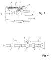
- FIG. 4 An internal combustion engine 9 is equipped with a supercharging turbocompressor 10.
- the turbocompressor 10 comprises of a turbine 11 placed in the exhaust gas flow leaving the engine 9 by an exhaust gas conduit 12 (dotted line) so as to be driven by the exhaust gases of the engine 9.
- the turbine 11 is connected by a shaft 13 to a compressor 14 mounted in the air intake conduit 3 of the engine 9.
- the box 1 is mounted upstream from a compressor 14 of the turbocompressor 10 in the direction of intake air movement which is shown schematically by the arrows A. Further, the box 1 is mounted downstream from an air filter 15 integrated in the air intake conduit 3.
- a charge air cooler 16 is mounted downstream from the compressor 14 and upstream from a damper flap 17 (not shown in detail).
- the box 1 is closed by a cover 2 attached by means of screws (not shown).
- the cover can be attached by means of welding, overwelding or other kinds of fixing means.
- the interior of the box 1 (interior chamber) fluidically connects for airflow with the interior airflow passage of the intake conduit 3.
- the box 1 is illustrated with sidewalls, a bottom wall and an open top which is closed over by the cover 2.
- a rotating anti-noise flap 4 molded of compatible plastic is mounted in the intake conduit 3 so as to be able to close this conduit 3.
- the anti-noise flap 4 is equipped with a rib 5 on the upper part thereof and on one surface thereof, where this rib 5 extends perpendicularly to the direction of movement A of the intake air in the conduit 3 and is extended on both sides of this flap by two journals 5 1 , 5 2 .
- the flap 4 may be constructed without a rib 5, whereby the journals 5 1 , 5 2 , are fixed to the sides of the flap 4 as shown in Figur 2 .
- These journals 5 1 , 5 2 are mobile to rotate in the two circular shoulders forming associated bearings 7 1 , 7 2 located on the side walls of the box 1, at the upper part of this box and on both sides thereof.
- the rib 5 and the journals 5 1 , 5 2 which extend therefrom make up the axle on which the anti-noise flap 4 articulates within the case or box 1 to open or close the airflow passage of the intake conduit 3.
- the geometry and in particular the mass of the anti-noise flap 4 are designed and calibrated or adjusted such that the force exerted by the airflow moving normally according to the arrow A in the intake conduit 3 drives the upward rotation of this flap by a predefined opening angle ⁇ against gravity so that it opens this conduit 3.
- the anti-noise flap rotates in the opposite direction under the action of gravity in order to close the conduit 3.
- the flap 4 may also be provided with a return spring to urge the flap 4 to rotate to the close position in the absence of a sufficient airflow force applied to the flap 4.
- a stop 8 formed in the box 1 blocks is operative to block any continuation of this rotation of the anti-noise flap 4 in the closing direction beyond the closed position of the flap (closed position indicated by the short-long dashed vertical line in Figure 3 ).
- This is advantageous to block reverse airflow (airflow in a direction opposite to arrow A) within the air intake conduit 3 such as may occur under the action of the gas reflux occurring in the direction opposite to the normal airflow direction A.
- Such gas reflux might be caused by surge phenomena of the turbocompressor.
- the reverse air flow is used to close the conduit 3 by the flap 4, so that the radiated noise is reduced.
- a anti-noise device which is constructed to be arranged in an intake air conduit 3 delivering an intake airflow to an internal combustion engine 9 equipped with a turbocompressor 10, wherein said turbocompressor 10 comprises a turbine 11 arranged in an exhaust gas conduit 12 and driven by exhaust gases produced by said engine 9 and delivered to said turbine 11 in said exhaust gas conduit 12. Further the turbocompressor 10 includes a compressor 14 arranged in said air intake conduit 3 operative to compress said intake airflow.
- a shaft 13 connects said turbine 11 to said compressor 14 and driveably transferring rotary motion from said turbine 11 to said compressor 14 for compression of said intake air.
- Said anti-noise device comprises an anti-noise flap 4 rotatably mounted within said air intake conduit 3 at a position upstream from said compressor 14 relative to said airflow, wherein in a closed position, said flap 4 closes off an airflow passage within said intake air conduit 3.
- the flap 4 is operable under the force of said airflow flowing to said compressor 14 to rotatably open from said closed position, permitting passage of said airflow through said airflow passage of said air intake conduit 3.
- the hinged flap 4 is operable under action of a gaseous reflux flowing is a direction opposite to said airflow to rotatably move said flap 4 to said closed position to close off said airflow passage of said air intake conduit.
Landscapes
- Engineering & Computer Science (AREA)
- Chemical & Material Sciences (AREA)
- Combustion & Propulsion (AREA)
- Mechanical Engineering (AREA)
- General Engineering & Computer Science (AREA)
- Supercharger (AREA)
Abstract
Anti-noise device for an internal combustion engine (9) equipped with a turbocompressor (10) for supercharging which is composed of a turbine (11) placed in the exhaust gas flow (12) leaving this engine (9) so as to be driven by these gases and connected by a shaft (13) to a compressor (14) mounted in the air intake conduit (3) of the engine (9) is described.
The anti-noise device includes a hinged flap (4) mounted within the air intake conduit (3) of the engine (9), upstream from the compressor (14) and capable of closing this conduit (3) under the action of a gaseous reflux coming towards it.
Description
- The present invention relates to an anti-noise device for an internal combustion engine equipped with a turbocompressor for supercharging intake air which is composed of a turbine placed in the exhaust gas flow leaving this engine so as to be driven by these gases and connected by a shaft to a compressor mounted in the air intake conduit of the engine. Further, the invention relates to an air intake system for an internal combustion engine equipped with a turbocompressor for supercharging comprising an anti-noise device.
- Automobile manufacturers are currently concerned about lowering as much as possible the noise nuisances created by the engines of their vehicles.
- Many parts can be the source of such nuisances among which the following can be given as examples: air filter boxes, engine cases, cylinder head covers, compressors of turbocompressors for supercharging, etc.
- In this context, mounting acoustic devices on various internal combustion engine air circulation tubes, especially on the air intake circuit for such engines, has already been proposed.
- It should in particular be noted that in supercharged internal combustion engines the compressor mounted in the air intake conduit can create aerodynamic instability phenomena causing flow rate inversions.
- Now, these phenomena are sources of noises extending over a broad frequency band which are particularly bothersome and very difficult to reduce; this is even more difficult because they only appear late in the development cycle.
- It is currently proposed to solve this drawback by equipping the air intake conduit of engines equipped with turbocompressors for supercharging with acoustic devices such as broad frequency band silencers or absorbing materials.
- As a general rule these acoustic devices are particularly sophisticated and costly and furthermore are often insufficiently effective.
- The purpose of the present invention is to remedy these drawbacks by proposing an anti-noise device for an internal combustion engine which is particularly simple and low-cost while also having a satisfactory effectiveness.
- According to the invention such an anti-noise device is characterized in that it is made up of a hinged flap mounted in the air intake conduit of the engine, upstream from the compressor and capable of closing this conduit under the action of a gaseous reflux coming towards it.
- Such an anti-noise flap, preferably made of a compatible plastic, corresponds to a particularly simple element with a reduced cost.
- According to a particularly advantageous feature of the invention, this anti-noise flap is hinged around an axle which is substantially perpendicular to the direction of airflow in the intake conduit.
- The parameters and in particular the mass of the anti-noise flap must be adjusted during design such that the force exerted by the normal gas flow moving in the intake conduit leads to the upward rotation of this flap to a predefined opening angle in order for it to open up this conduit.
- In the absence of such a force, the anti-noise flap rotates in the opposite direction under the action of its weight or a spring or a mass in order to close the intake conduit.
- The stop provided on this conduit blocks the anti-noise flap from continuing any rotation beyond the closed position in this inverse direction under the action of the gaseous reflux in the direction opposite the normal direction of air movement.
- Thus the intake conduit remains closed which makes it possible to very effectively reduce the nuisance noises induced by surging phenomena.
- According to another feature of the invention, the anti-noise flap can advantageously be mounted in a box integrated into the air intake conduit.
- Such a box is preferably closed by a cover with a sealing joint placed between the box and cover.
- The features of the anti-noise device which is the subject of the invention are described in greater detail by referring to the attached nonlimiting drawings in which:
-
Figure 1 is a perspective view of a case or box of an anti-noise device integrated in the air intake conduit of a supercharged internal combustion engine. -
Figure 2 is a perspective view corresponding toFigure 1 but in which the cover of the box has been removed. -
Figure 3 is a schematic longitudinal section view of the box shown inFigure 1 . -
Figure 4 illustrates schematically the air intake system of a supercharged internal combustion engine equipped with the anti-noise device shown inFigures 1 to 3 . - First, the arrangement of a case or
housing box 1 comprising an anti-noise device is described with reference toFigure 4 . Aninternal combustion engine 9 is equipped with asupercharging turbocompressor 10. Theturbocompressor 10 comprises of aturbine 11 placed in the exhaust gas flow leaving theengine 9 by an exhaust gas conduit 12 (dotted line) so as to be driven by the exhaust gases of theengine 9. Theturbine 11 is connected by ashaft 13 to acompressor 14 mounted in theair intake conduit 3 of theengine 9. Thebox 1 is mounted upstream from acompressor 14 of theturbocompressor 10 in the direction of intake air movement which is shown schematically by the arrows A. Further, thebox 1 is mounted downstream from anair filter 15 integrated in theair intake conduit 3. Acharge air cooler 16 is mounted downstream from thecompressor 14 and upstream from a damper flap 17 (not shown in detail). - According to
Figures 1-3 thebox 1 is closed by acover 2 attached by means of screws (not shown). Alternatively the cover can be attached by means of welding, overwelding or other kinds of fixing means. - According to
Figures 2 and3 the interior of the box 1 (interior chamber) fluidically connects for airflow with the interior airflow passage of theintake conduit 3. Thebox 1 is illustrated with sidewalls, a bottom wall and an open top which is closed over by thecover 2. - A rotating
anti-noise flap 4 molded of compatible plastic is mounted in theintake conduit 3 so as to be able to close thisconduit 3. - As shown in
Figure 2 , theanti-noise flap 4 is equipped with arib 5 on the upper part thereof and on one surface thereof, where thisrib 5 extends perpendicularly to the direction of movement A of the intake air in theconduit 3 and is extended on both sides of this flap by twojournals flap 4 may be constructed without arib 5, whereby thejournals flap 4 as shown inFigur 2 - These
journals box 1, at the upper part of this box and on both sides thereof. - The
rib 5 and thejournals anti-noise flap 4 articulates within the case orbox 1 to open or close the airflow passage of theintake conduit 3. - According to
Figure 3 , the geometry and in particular the mass of theanti-noise flap 4 are designed and calibrated or adjusted such that the force exerted by the airflow moving normally according to the arrow A in theintake conduit 3 drives the upward rotation of this flap by a predefined opening angle α against gravity so that it opens thisconduit 3. - In a manner not shown in the figures, in the absence of such a force the anti-noise flap rotates in the opposite direction under the action of gravity in order to close the
conduit 3. Theflap 4 may also be provided with a return spring to urge theflap 4 to rotate to the close position in the absence of a sufficient airflow force applied to theflap 4. - According to
Figure 3 , astop 8 formed in thebox 1 blocks is operative to block any continuation of this rotation of theanti-noise flap 4 in the closing direction beyond the closed position of the flap (closed position indicated by the short-long dashed vertical line inFigure 3 ). This is advantageous to block reverse airflow (airflow in a direction opposite to arrow A) within theair intake conduit 3 such as may occur under the action of the gas reflux occurring in the direction opposite to the normal airflow direction A. - Such gas reflux might be caused by surge phenomena of the turbocompressor. According to the invention the reverse air flow is used to close the
conduit 3 by theflap 4, so that the radiated noise is reduced. - In summary, a anti-noise device is described, which is constructed to be arranged in an
intake air conduit 3 delivering an intake airflow to aninternal combustion engine 9 equipped with aturbocompressor 10, wherein saidturbocompressor 10 comprises aturbine 11 arranged in anexhaust gas conduit 12 and driven by exhaust gases produced by saidengine 9 and delivered to saidturbine 11 in saidexhaust gas conduit 12. Further theturbocompressor 10 includes acompressor 14 arranged in saidair intake conduit 3 operative to compress said intake airflow. Ashaft 13 connects saidturbine 11 to saidcompressor 14 and driveably transferring rotary motion from saidturbine 11 to saidcompressor 14 for compression of said intake air. - Said anti-noise device comprises an
anti-noise flap 4 rotatably mounted within saidair intake conduit 3 at a position upstream from saidcompressor 14 relative to said airflow, wherein in a closed position, saidflap 4 closes off an airflow passage within saidintake air conduit 3. Theflap 4 is operable under the force of said airflow flowing to saidcompressor 14 to rotatably open from said closed position, permitting passage of said airflow through said airflow passage of saidair intake conduit 3. The hingedflap 4 is operable under action of a gaseous reflux flowing is a direction opposite to said airflow to rotatably move saidflap 4 to said closed position to close off said airflow passage of said air intake conduit.
Claims (7)
- Anti-noise device for an internal combustion engine (9) equipped with a turbocompressor (10) for supercharging which is composed of a turbine (11) placed in the exhaust gas flow leaving this engine (9) so as to be driven by these gases and connected by a shaft (13) to a compressor (14) mounted in the air intake conduit (3) of the engine (9),
characterized in that
the anti-noise device includes a hinged flap (4) mounted in the air intake conduit (3) of the engine (9), upstream from the compressor (14) and capable of closing this conduit (3) under the action of a gaseous reflux coming towards it. - Device according to claim 1,
characterized in that
the anti-noise flap (4) is hinged around an axle (5, 51, 52) which is positioned substantially perpendicular to the direction of airflow A in the intake conduit (3). - Device according to any one of claims 1 and 2,
characterized in that
the anti-noise flap (4) is mounted in a housing box (1) integrated into the air intake conduit (3). - Device according to any one of claims 1 to 3,
characterized in that
said anti-noise flap (4) is rotatably mounted within an internal airflow chamber of a housing box (1), said housing box (1) forming part of said air intake conduit (3), wherein said housing box (1) is integrated into said air intake conduit (3) such that airflow in said airflow passage of said air intake conduit (3) passes through said chamber of said housing box (1). - Device according to any one of the proceeding claims,
characterized in that
said flap (4) has a mass calibrated to counteract a force applied by said airflow such that airflow generated force acting on said flap (4) drives an upward rotation of said flap (4) to said open position approximating a predefined opening angle, said opening angle taken relative to said closed position. - Device according to any one of the proceeding claims,
characterized in that
said anti-rotation device includes a spring acting upon said flap (4) to urge said flap (4) into said closed position. - Air intake system for an internal combustion engine (9) equipped with a turbocompressor (10) for supercharging, whereby the air intake system comprises an anti-noise device according to any one of the proceeding claim.
Applications Claiming Priority (1)
| Application Number | Priority Date | Filing Date | Title |
|---|---|---|---|
| FR1051619A FR2957130B1 (en) | 2010-03-05 | 2010-03-05 | ANTI-NOISE DEVICE FOR THE AIR INTAKE DUCT OF A SUPERIOR INTERNAL COMBUSTION ENGINE |
Publications (1)
| Publication Number | Publication Date |
|---|---|
| EP2363591A1 true EP2363591A1 (en) | 2011-09-07 |
Family
ID=42985339
Family Applications (1)
| Application Number | Title | Priority Date | Filing Date |
|---|---|---|---|
| EP11157214A Withdrawn EP2363591A1 (en) | 2010-03-05 | 2011-03-07 | Anti-noise device for the air intake conduit of a supercharged internal combustion engine |
Country Status (3)
| Country | Link |
|---|---|
| US (1) | US8276707B2 (en) |
| EP (1) | EP2363591A1 (en) |
| FR (1) | FR2957130B1 (en) |
Families Citing this family (12)
| Publication number | Priority date | Publication date | Assignee | Title |
|---|---|---|---|---|
| USD762247S1 (en) * | 2013-03-26 | 2016-07-26 | Advanced Plow Engineering, Inc. | Automotive air intake system |
| USD708231S1 (en) * | 2013-03-26 | 2014-07-01 | Advanced Flow Engineering, Inc. | Automotive air intake system |
| USD749134S1 (en) * | 2013-07-08 | 2016-02-09 | Advanced Flow Engineering | Air intake system |
| USD762735S1 (en) * | 2013-07-08 | 2016-08-02 | Advanced Flow Engineering, Inc. | Automotive air intake system |
| USD754208S1 (en) * | 2013-07-08 | 2016-04-19 | Advanced Flow Engineering | Air intake system |
| USD762736S1 (en) * | 2013-10-15 | 2016-08-02 | Advanced Flow Engineering, Inc. | Air intake system |
| US9951690B2 (en) | 2014-08-19 | 2018-04-24 | Pratt & Whitney Canada Corp. | Low noise aeroengine inlet system |
| US10054050B2 (en) | 2014-08-19 | 2018-08-21 | Pratt & Whitney Canada Corp. | Low noise aeroengine inlet system |
| US9957889B2 (en) | 2014-08-19 | 2018-05-01 | Pratt & Whitney Canada Corp. | Low noise aeroengine inlet system |
| FR3066547B1 (en) * | 2017-05-17 | 2021-01-08 | Renault Sas | SUPPLY AIR INTAKE SYSTEM IN A MOTOR VEHICLE INTERNAL COMBUSTION ENGINE INCLUDING A NOISE REDUCTION MODULE |
| USD907065S1 (en) * | 2019-08-09 | 2021-01-05 | Wehrli Custom Fabrication, Inc. | Adapter for installation of a turbocharger |
| USD967196S1 (en) * | 2021-07-21 | 2022-10-18 | Advanced Flow Engineering, Inc. | Air intake system with window |
Citations (8)
| Publication number | Priority date | Publication date | Assignee | Title |
|---|---|---|---|---|
| US4445336A (en) * | 1981-02-06 | 1984-05-01 | Honda Giken Kogyo Kabushiki Kaisha | Internal combustion engine equipped with supercharger |
| JPS60134862U (en) * | 1984-02-21 | 1985-09-07 | 日産自動車株式会社 | Intake system for turbocharged engine |
| DE4331943A1 (en) * | 1993-09-02 | 1995-03-16 | Man Nutzfahrzeuge Ag | Supercharging system for air-compressing internal combustion engines |
| US5615554A (en) * | 1995-02-24 | 1997-04-01 | Ab Volvo | Supercharged internal combustion engine |
| EP0889228A1 (en) * | 1997-07-03 | 1999-01-07 | Nissan Motor Co., Ltd. | Intake noise reducing device for internal combustion engine |
| US6332442B1 (en) * | 1998-04-16 | 2001-12-25 | Toyoda Gosei Co., Ltd. | Intake air duct |
| US20020170287A1 (en) * | 2000-07-24 | 2002-11-21 | Shinya Hirota | Exhaust gas purification device |
| DE202006011933U1 (en) * | 2006-08-02 | 2007-12-06 | Mann + Hummel Gmbh | Muffler means |
-
2010
- 2010-03-05 FR FR1051619A patent/FR2957130B1/en not_active Expired - Fee Related
-
2011
- 2011-03-07 EP EP11157214A patent/EP2363591A1/en not_active Withdrawn
- 2011-03-07 US US13/041,633 patent/US8276707B2/en not_active Expired - Fee Related
Patent Citations (8)
| Publication number | Priority date | Publication date | Assignee | Title |
|---|---|---|---|---|
| US4445336A (en) * | 1981-02-06 | 1984-05-01 | Honda Giken Kogyo Kabushiki Kaisha | Internal combustion engine equipped with supercharger |
| JPS60134862U (en) * | 1984-02-21 | 1985-09-07 | 日産自動車株式会社 | Intake system for turbocharged engine |
| DE4331943A1 (en) * | 1993-09-02 | 1995-03-16 | Man Nutzfahrzeuge Ag | Supercharging system for air-compressing internal combustion engines |
| US5615554A (en) * | 1995-02-24 | 1997-04-01 | Ab Volvo | Supercharged internal combustion engine |
| EP0889228A1 (en) * | 1997-07-03 | 1999-01-07 | Nissan Motor Co., Ltd. | Intake noise reducing device for internal combustion engine |
| US6332442B1 (en) * | 1998-04-16 | 2001-12-25 | Toyoda Gosei Co., Ltd. | Intake air duct |
| US20020170287A1 (en) * | 2000-07-24 | 2002-11-21 | Shinya Hirota | Exhaust gas purification device |
| DE202006011933U1 (en) * | 2006-08-02 | 2007-12-06 | Mann + Hummel Gmbh | Muffler means |
Also Published As
| Publication number | Publication date |
|---|---|
| US20110214936A1 (en) | 2011-09-08 |
| FR2957130A1 (en) | 2011-09-09 |
| US8276707B2 (en) | 2012-10-02 |
| FR2957130B1 (en) | 2012-06-22 |
Similar Documents
| Publication | Publication Date | Title |
|---|---|---|
| US8276707B2 (en) | Anti-noise device for the air intake conduit of a supercharged internal combustion engine | |
| CN103732879B (en) | Exhaust turbocharger with ball-tipped wastegate valve and strain-relieved crank arm | |
| JP2012225297A (en) | Engine exhaust device | |
| US6899531B2 (en) | Secondary air turbocharger with sound absorbing insulating material | |
| CN104428538A (en) | Compressor for supercharger of internal combustion engine | |
| US8360016B2 (en) | Engine blower | |
| JP6127070B2 (en) | Exhaust gas turbocharger | |
| JP6331603B2 (en) | Intake device for an internal combustion engine with a supercharger | |
| JP5440277B2 (en) | Blow-by gas processing device for turbocharged engine | |
| JP6011186B2 (en) | Turbocharger | |
| KR20150132219A (en) | A compact rotary wastegate valve | |
| US10337475B2 (en) | Air intake device of engine with supercharger | |
| US10018164B2 (en) | Gas compressor pressure relief noise reduction | |
| US20140165561A1 (en) | Supercharger Turbocharger Bypass Back Draft Inlet Damper for Series Operation | |
| JP2005061342A (en) | Air bypass passage structure of turbocharged engine | |
| JP2006336539A (en) | Intake structure of turbocharged engine | |
| CN111472868B (en) | Internal combustion engine for vehicle | |
| JP2019100224A (en) | Internal combustion engine for vehicle | |
| US20110232280A1 (en) | Turbocharger diverter valve | |
| CN204003194U (en) | Air cleaner | |
| JPH06323147A (en) | Supercharger | |
| JP7191466B2 (en) | internal combustion engine silencer | |
| JP2020050098A (en) | Intake air introduction device of vehicle | |
| JPH06108866A (en) | Supercharger cooling structure for internal combustion engine with supercharger | |
| JPS6218665Y2 (en) |
Legal Events
| Date | Code | Title | Description |
|---|---|---|---|
| PUAI | Public reference made under article 153(3) epc to a published international application that has entered the european phase |
Free format text: ORIGINAL CODE: 0009012 |
|
| AK | Designated contracting states |
Kind code of ref document: A1 Designated state(s): AL AT BE BG CH CY CZ DE DK EE ES FI FR GB GR HR HU IE IS IT LI LT LU LV MC MK MT NL NO PL PT RO RS SE SI SK SM TR |
|
| AX | Request for extension of the european patent |
Extension state: BA ME |
|
| 17P | Request for examination filed |
Effective date: 20120307 |
|
| 17Q | First examination report despatched |
Effective date: 20120912 |
|
| STAA | Information on the status of an ep patent application or granted ep patent |
Free format text: STATUS: THE APPLICATION IS DEEMED TO BE WITHDRAWN |
|
| 18D | Application deemed to be withdrawn |
Effective date: 20130615 |