EP2363319A1 - Vehicular seat, in particular watercraft seat and method for making the same - Google Patents
Vehicular seat, in particular watercraft seat and method for making the same Download PDFInfo
- Publication number
- EP2363319A1 EP2363319A1 EP11150975A EP11150975A EP2363319A1 EP 2363319 A1 EP2363319 A1 EP 2363319A1 EP 11150975 A EP11150975 A EP 11150975A EP 11150975 A EP11150975 A EP 11150975A EP 2363319 A1 EP2363319 A1 EP 2363319A1
- Authority
- EP
- European Patent Office
- Prior art keywords
- cushion member
- seat
- covering sheet
- bottom plate
- disposed
- Prior art date
- Legal status (The legal status is an assumption and is not a legal conclusion. Google has not performed a legal analysis and makes no representation as to the accuracy of the status listed.)
- Granted
Links
Images





Classifications
-
- B—PERFORMING OPERATIONS; TRANSPORTING
- B60—VEHICLES IN GENERAL
- B60N—SEATS SPECIALLY ADAPTED FOR VEHICLES; VEHICLE PASSENGER ACCOMMODATION NOT OTHERWISE PROVIDED FOR
- B60N2/00—Seats specially adapted for vehicles; Arrangement or mounting of seats in vehicles
- B60N2/70—Upholstery springs ; Upholstery
- B60N2/7017—Upholstery springs ; Upholstery characterised by the manufacturing process; manufacturing upholstery or upholstery springs not otherwise provided for
-
- B—PERFORMING OPERATIONS; TRANSPORTING
- B29—WORKING OF PLASTICS; WORKING OF SUBSTANCES IN A PLASTIC STATE IN GENERAL
- B29C—SHAPING OR JOINING OF PLASTICS; SHAPING OF MATERIAL IN A PLASTIC STATE, NOT OTHERWISE PROVIDED FOR; AFTER-TREATMENT OF THE SHAPED PRODUCTS, e.g. REPAIRING
- B29C44/00—Shaping by internal pressure generated in the material, e.g. swelling or foaming ; Producing porous or cellular expanded plastics articles
- B29C44/02—Shaping by internal pressure generated in the material, e.g. swelling or foaming ; Producing porous or cellular expanded plastics articles for articles of definite length, i.e. discrete articles
- B29C44/12—Incorporating or moulding on preformed parts, e.g. inserts or reinforcements
- B29C44/1228—Joining preformed parts by the expanding material
- B29C44/1233—Joining preformed parts by the expanding material the preformed parts being supported during expanding
- B29C44/1238—Joining preformed parts by the expanding material the preformed parts being supported during expanding and having flexible and solid areas
-
- B—PERFORMING OPERATIONS; TRANSPORTING
- B60—VEHICLES IN GENERAL
- B60N—SEATS SPECIALLY ADAPTED FOR VEHICLES; VEHICLE PASSENGER ACCOMMODATION NOT OTHERWISE PROVIDED FOR
- B60N2/00—Seats specially adapted for vehicles; Arrangement or mounting of seats in vehicles
- B60N2/56—Heating or ventilating devices
- B60N2/5607—Heating or ventilating devices characterised by convection
- B60N2/5621—Heating or ventilating devices characterised by convection by air
- B60N2/5664—Heating or ventilating devices characterised by convection by air with unforced air circulation, i.e. not using a fan or the like
-
- B—PERFORMING OPERATIONS; TRANSPORTING
- B60—VEHICLES IN GENERAL
- B60N—SEATS SPECIALLY ADAPTED FOR VEHICLES; VEHICLE PASSENGER ACCOMMODATION NOT OTHERWISE PROVIDED FOR
- B60N2/00—Seats specially adapted for vehicles; Arrangement or mounting of seats in vehicles
- B60N2/58—Seat coverings
- B60N2/5816—Seat coverings attachments thereof
-
- B—PERFORMING OPERATIONS; TRANSPORTING
- B60—VEHICLES IN GENERAL
- B60N—SEATS SPECIALLY ADAPTED FOR VEHICLES; VEHICLE PASSENGER ACCOMMODATION NOT OTHERWISE PROVIDED FOR
- B60N2/00—Seats specially adapted for vehicles; Arrangement or mounting of seats in vehicles
- B60N2/70—Upholstery springs ; Upholstery
- B60N2/7023—Coach-like constructions
- B60N2/7035—Cushions
-
- B—PERFORMING OPERATIONS; TRANSPORTING
- B62—LAND VEHICLES FOR TRAVELLING OTHERWISE THAN ON RAILS
- B62J—CYCLE SADDLES OR SEATS; AUXILIARY DEVICES OR ACCESSORIES SPECIALLY ADAPTED TO CYCLES AND NOT OTHERWISE PROVIDED FOR, e.g. ARTICLE CARRIERS OR CYCLE PROTECTORS
- B62J1/00—Saddles or other seats for cycles; Arrangement thereof; Component parts
- B62J1/12—Box-shaped seats; Bench-type seats, e.g. dual or twin seats
-
- Y—GENERAL TAGGING OF NEW TECHNOLOGICAL DEVELOPMENTS; GENERAL TAGGING OF CROSS-SECTIONAL TECHNOLOGIES SPANNING OVER SEVERAL SECTIONS OF THE IPC; TECHNICAL SUBJECTS COVERED BY FORMER USPC CROSS-REFERENCE ART COLLECTIONS [XRACs] AND DIGESTS
- Y10—TECHNICAL SUBJECTS COVERED BY FORMER USPC
- Y10T—TECHNICAL SUBJECTS COVERED BY FORMER US CLASSIFICATION
- Y10T29/00—Metal working
- Y10T29/49—Method of mechanical manufacture
- Y10T29/4998—Combined manufacture including applying or shaping of fluent material
Definitions
- the present invention relates to a vehicular seat, a watercraft seat, a method for making the vehicular seat, and a method for making the watercraft seat.
- Known vehicular seat and watercraft seat include a first cushion member formed of urethane and covered with a seat skin and a second cushion member formed of a thermoplastic elastomer and disposed between the first cushion member and a bottom plate (see, for example, Japanese Patent Application No. JP-A-2007-175482 ).
- the first cushion member and the second cushion member are formed separately from each other and thereafter bonded together.
- a one-piece molding process may be possible, in which the first cushion member of urethane is foamed on the second cushion member of thermoplastic elastomer.
- a foaming pressure causes the first cushion member to bite into and be fused with the second cushion member, resulting in degraded riding comfort.
- the present invention has been made in view of the foregoing situations and it is an object of the present invention to provide a vehicular seat, a watercraft seat, a method for making the vehicular seat, and a method for making the watercraft seat that can achieve a favorable riding comfort, reduce the number of work processes involved, and reduce the manufacturing cost even by foaming a first cushion member of urethane on a second cushion member of a thermoplastic elastomer to make an integrated assembly of the first cushion member of urethane and the second cushion member.
- a first aspect of the present invention provides a vehicular seat that includes a first cushion member formed of urethane, the first cushion member being covered with a seat skin; a second cushion member formed of a thermoplastic elastomer, the second cushion member being disposed between the first cushion member and a bottom plate; and a covering sheet disposed between the first cushion member and the second cushion member.
- the covering sheet is disposed on the second cushion member on a side thereof adjacent the first cushion member, and not on an entire surface or part of a side thereof adjacent the bottom plate.
- the bottom plate has a rib disposed on an upper surface thereof, the rib extending toward a side of the second cushion member.
- a fourth aspect of the present invention provides a watercraft seat that includes a first cushion member formed of urethane, the first cushion member being covered with a seat skin; a second cushion member formed of a thermoplastic elastomer, the second cushion member being disposed between the first cushion member and a bottom plate; and a covering sheet disposed between the first cushion member and the second cushion member.
- the bottom plate has a rib disposed on an upper surface thereof, the rib extending toward a side of the second cushion member.
- a seventh aspect of the present invention provides a method for making a vehicular seat, the vehicular seat including: a first cushion member formed of urethane, the first cushion member being covered with a seat skin; a second cushion member formed of a thermoplastic elastomer, the second cushion member being disposed between the first cushion member and a bottom plate; and a covering sheet disposed between the first cushion member and the second cushion member.
- the covering sheet is disposed between the first cushion member and the second cushion member. Even if the first cushion member of urethane is foamed to be integrally formed on the second cushion member of the thermoplastic elastomer, the foamed first cushion member is blocked by the covering sheet. This eliminates the likelihood that the first cushion member and the second cushion member will be fused together, so that favorable riding comfort of the vehicular seat can be achieved.
- the first cushion member can be foamed to be integrated with the second cushion member. This reduces the number of work processes involved, so that a manufacturing cost of the vehicular seat can be reduced.
- the covering sheet is disposed on the side of the second cushion member adjacent the first cushion member and not on the entire surface or part of the side of the second cushion member adjacent the bottom plate. Air inside the second cushion member can therefore be aspirated on the side of the bottom plate according to movement of the occupant, so that favorable riding comfort of the vehicular seat can be achieved.
- the covering sheet is disposed between the first cushion member and the second cushion member. Even if the first cushion member of urethane is foamed to be integrally formed on the second cushion member of the thermoplastic elastomer, the foamed first cushion member is blocked by the covering sheet. This eliminates the likelihood that the first cushion member and the second cushion member will be fused together, so that favorable riding comfort of the watercraft seat can be achieved.
- the first cushion member can be foamed to be integrated with the second cushion member. This reduces the number of work processes involved, so that a manufacturing cost of the watercraft seat can be reduced.
- the covering sheet is disposed on the side of the second cushion member adjacent the first cushion member and not on the entire surface or part of the side of the second cushion member adjacent the bottom plate. Air inside the second cushion member can therefore be aspirated on the side of the bottom plate according to movement of the occupant, so that favorable riding comfort of the watercraft seat can be achieved.
- the rib extending toward the side of the second cushion member is disposed on the upper surface of the bottom plate.
- the second cushion member can therefore be effectively bled of air according to the movement of the occupant, so that favorable riding comfort of the watercraft seat can be achieved.
- the method includes the steps of: forming the second cushion member; affixing the covering sheet generally to the second cushion member excluding part thereof; setting the second cushion member, to which the covering sheet is affixed, into the first mold; loading the urethane material into the second mold; closing the first mold and the second mold; foaming the urethane material to thereby integrally form the first cushion member on a surface of the covering sheet affixed to the second cushion member; removing the integrated assembly of the first cushion member, the second cushion member, and the covering sheet from the first mold and the second mold; and mounting the bottom plate on a lower surface of the integrated assembly of the first cushion member, the second cushion member, and the covering sheet, covering a surface of the first cushion member with the seat skin, and mounting the seat skin on the bottom plate.
- the vehicular seat having the first and second cushion members integrated together can therefore be easily obtained by foaming the urethane material.
- the method includes the steps of: forming the second cushion member; affixing the covering sheet generally to the second cushion member excluding part thereof; setting the second cushion member, to which the covering sheet is affixed, into the first mold; loading the urethane material into the second mold; closing the first mold and the second mold; foaming the urethane material to thereby integrally form the first cushion member on a surface of the covering sheet affixed to the second cushion member; removing the integrated assembly of the first cushion member, the second cushion member, and the covering sheet from the first mold and the second mold; and mounting the bottom plate on a lower surface of the integrated assembly of the first cushion member, the second cushion member, and the covering sheet, covering a surface of the first cushion member with the seat skin, and mounting the seat skin on the bottom plate.
- the watercraft seat having the first and second cushion members integrated together can therefore be easily obtained by foaming the urethane material.
- the motorcycle 1 includes a vehicle body frame 2, a pair of left and right front forks 3, a steering handlebar 4, a front wheel 5, a rear fork (swing arm) 6, a rear wheel 7, an engine 8, a fuel tank 9, a vehicular seat 10, a rider's step 12, a passenger's step 13, side trunks 14, and a cowling 15. More specifically, the front forks 3 are rotatably supported at a front end portion of the vehicle body frame 2. The handlebar 4 is attached on an upper end portion of the front forks 3. The front wheel 5 is rotatably supported by the front forks 3.
- Exhaust pipes 8A are connected to a cylinder portion of the engine 8. Each of the exhaust pipes 8A extends downwardly and, at a position downward of the engine 8, bends before being connected to a muffler 8B disposed rearwardly of the engine 8.
- the cowling 15 includes a front cowl 17 and a rear cowl 18.
- the front cowl 17 covers a front portion of the vehicle body and has an upper end portion extending along a main frame 16 of the vehicle body frame 2.
- the rear cowl 18 covers a lower portion of the vehicular seat 10, specifically, a rear portion of the vehicle body.
- the front cowl 17 includes an upper cowl 17a disposed at a front end of the vehicle body, a middle cowl 17b for covering a side portion of the engine 8, and an under cowl 17c for covering a lower portion of the engine 8 (lower portion of the exhaust pipes 8A).
- reference numeral 21 denotes a windshield
- reference numeral 22 denotes a headlight
- reference numeral 23 denotes a side mirror
- reference numeral 24 denotes a front flasher
- reference numeral 25 denotes a rear grip
- reference numeral 26 denotes a front fender
- reference numeral 27 denotes a rear fender
- reference numeral 28 denotes a stand.
- the protruding portion 48 supports a lower surface of the second cushion member 42 and enhances stiffness of the bottom plate 43.
- a plurality of ribs 49 (a total of 12 on the left and right sides shown in Fig. 3 ) is formed on an upper surface of the bottom of the recessed portion 45. The ribs extend toward the side of the second cushion member 42 to support the lower surface of the second cushion member 42 and enhance stiffness of the bottom plate 43.
- the second cushion member 42 is formed by cutting a block-like thermoplastic elastomer base material. Referring to Fig. 3 , the second cushion member 42 is formed into a shape having a rectangular cross section and fitted in the recessed portion 45 of the bottom plate 43. According to the first embodiment of the present invention, it is possible to make the occupant feel less corners of the second cushion member 42 when seated by adjusting a thickness of the first cushion member 41 and that of the covering sheet 44. The vehicular seat 10 is thereby allowed to exhibit a uniform feel.
- the second cushion member 42 is a thermoplastic elastomer striate body of an isotropic gel-like viscoelastic body type that is coupled three-dimensionally into a net-like thermoplastic elastomer.
- the covering sheet 44 is affixed to a surface of the second cushion member 42 on the side adjacent the first cushion member 41.
- the covering sheet 44 is not affixed to part of a surface of the second cushion member 42 on the side of the bottom plate 43.
- the covering sheet 44 is affixed to an upper surface, side surfaces, and part of a bottom surface of the second cushion member 42.
- the first cushion member 41 is formed integrally on a surface of the covering sheet 44 affixed to the second cushion member 42 by foaming a urethane material in molds 81, 82 to be described later. This causes the covering sheet 44 to be in tight contact with the first cushion member 41 by a foaming pressure, facilitating clearance control.
- the covering sheet 44 is affixed to a side of the second cushion member 42 adjacent the first cushion member 41 and is not to part of a side of the second cushion member 42 adjacent the bottom plate 43. Air inside the second cushion member 42 can therefore be aspirated on the side of the bottom plate 43 according to movement of the occupant, so that favorable riding comfort of the vehicular seat 10 can be achieved.
- the second cushion member 42 is formed by cutting operations into a shape having the rectangular cross section. This eliminates the need for forming an obliquely cut surface 52a through cutting operations as in a second cushion member 52 of a second embodiment of the present invention to be described later. As a result, the manufacturing cost of the vehicular seat 10 can be further reduced.
- a vehicular seat according to a second embodiment of the present invention will be described below with reference to Fig. 4 .
- Like or corresponding parts are identified by the same reference numerals as those used for the first embodiment of the present invention and descriptions for those parts will be omitted or simplified.
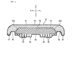
- a vehicular seat 10 includes a first cushion member 41, a second cushion member 52, and a covering sheet 44. More specifically, the first cushion member 41 formed of urethane is covered with a seat skin 40. The second cushion member 52 formed of a thermoplastic elastomer is disposed between the first cushion member 41 and a bottom plate 43. The covering sheet 44 is disposed between the first cushion member 41 and the second cushion member 52.
- the second cushion member 52 is formed by cutting a block-like thermoplastic elastomer base material. Referring to Fig. 4 , the second cushion member 52 has a straight-line obliquely cut surface 52a on each side of an upper portion of outer end portions in the vehicle width direction thereof. The obliquely cut surface 52a is formed such that the second cushion member 52 has a thickness that gradually decreases toward the outside in the vehicle width direction.
- the second cushion member 52 is formed to have the obliquely cut surfaces 52a through cutting operations. This eliminates the need for forming a protruding portion 62b and an arcuate surface 62c by thermal forming as in a second cushion member 62 of a third embodiment of the present invention to be described later. As a result, the manufacturing cost of the vehicular seat 10 can be reduced.
- the second cushion member 52 has the obliquely cut surfaces 52a formed at the upper portions on the outer end portions in the vehicle width direction thereof. This allows an entire seat surface of the vehicular seat 10 to exhibit a uniform feel during seating.
- the second cushion member 62 is formed by thermally forming a block-like thermoplastic elastomer base material.
- the second cushion member 62 has a main unit portion 62a and protruding portions 62b. More specifically, the main unit portion 62a is fitted into a recessed portion 45 in the bottom plate 43.
- Each of the protruding portions 62b protrudes outwardly from an outer end surface in the vehicle width direction of the main unit portion 62a and is placed on a curved portion 46 of the bottom plate 43.
- an arcuate surface 62c is formed at an upper corner of each of the protruding portions 62b.
- the second cushion member 62 includes the main unit portion 62a and the protruding portions 62b that protrude outwardly from the upper portions of the outer end surfaces in the vehicle width direction of the main unit portion 62a.
- Each of the protruding portions 62b includes the arcuate surface 62c formed at each of the upper corners of the protruding portions 62b. This allows both sides of the vehicular seat 10 to exhibit a uniform feel during seating. Riding comfort of the vehicular seat 10 can therefore be further enhanced.
- the present invention has been described with particularity relative to the detailed description of the exemplary preferred first through third embodiments, in which the present invention is applied to the vehicular seat 10 of the motorcycle 1.
- the present invention may still be applied to a vehicular seat 71 of a four-wheeled vehicle as shown in Fig. 6 or a watercraft seat 72 of a saddle riding type watercraft as shown in Fig. 7 .
- the second cushion member 52 of the second embodiment of the present invention is used in the vehicular seat 71 of the four-wheeled vehicle.
- the second cushion member 42 or 62 of the first or third embodiment of the present invention may instead be used.
- the second cushion member 42 of the first embodiment of the present invention is used in the watercraft seat 72 of the saddle riding type watercraft.
- the second cushion member 52 or 62 of the second or third embodiment of the present invention may instead be used.
- a method for making the vehicular seat or the watercraft seat according to an embodiment of the present invention will be described below with reference to Figs. 8 and 9 .
- the vehicular seat 10 according to the second embodiment of the present invention will be used as an example.
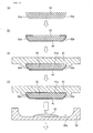
- the method for making the vehicular seat 10 includes the steps of: forming the second cushion member 52 of the thermoplastic elastomer of a net-like structure by cutting (see Fig. 8(a) ); affixing the covering sheet 44 generally to the second cushion member 52 excluding part of the lower surface of the second cushion member 52 (see Fig. 8(b) ); setting the second cushion member 52, to which the covering sheet 44 is affixed, into a recessed portion 81 a formed in a lower surface of an upper mold (a first mold) 81 (see Fig. 8(c) ); loading a urethane material 83 into a recessed portion 82b formed in an upper surface of a lower mold (a second mold) 82 (see Fig.
- the vehicular seat 71 and the watercraft seat 72 are made by the same making processes.
- the vehicular seat according to the embodiments of the present invention are suited to those of motorcycles and saddle riding type vehicles and of automobiles and the watercraft seat according to the embodiments of the present invention are suited to those of saddle riding type watercrafts.
- the present invention may be applied to seats in industrial vehicles, trains, aircraft, and other various types of vehicles.
- the present invention is directed to provide a vehicular seat, a watercraft seat, a method for making the vehicular seat, and a method for making the watercraft seat that can achieve a favorable riding comfort, reduce the number of work processes involved, and reduce a manufacturing cost even by foaming a first cushion member of urethane on a second cushion member of a thermoplastic elastomer to make an integrated assembly of the first cushion member of urethane and the second cushion member.
- a vehicular seat 10 includes a first cushion member 41 formed of urethane and covered with a seat skin 40 and a second cushion member 42 formed of a thermoplastic elastomer and disposed between the first cushion member 41 and a bottom plate 43.
- a covering sheet 44 is disposed between the first cushion member 41 and the second cushion member 42.
Landscapes
- Engineering & Computer Science (AREA)
- Mechanical Engineering (AREA)
- Aviation & Aerospace Engineering (AREA)
- Transportation (AREA)
- Manufacturing & Machinery (AREA)
- Seats For Vehicles (AREA)
- Mattresses And Other Support Structures For Chairs And Beds (AREA)
Abstract
Description
- The present invention relates to a vehicular seat, a watercraft seat, a method for making the vehicular seat, and a method for making the watercraft seat.
- Known vehicular seat and watercraft seat include a first cushion member formed of urethane and covered with a seat skin and a second cushion member formed of a thermoplastic elastomer and disposed between the first cushion member and a bottom plate (see, for example, Japanese Patent Application No.
JP-A-2007-175482 - In the vehicular seat and the watercraft seat disclosed in Japanese Patent Application No.
JP-A-2007-175482 - The present invention has been made in view of the foregoing situations and it is an object of the present invention to provide a vehicular seat, a watercraft seat, a method for making the vehicular seat, and a method for making the watercraft seat that can achieve a favorable riding comfort, reduce the number of work processes involved, and reduce the manufacturing cost even by foaming a first cushion member of urethane on a second cushion member of a thermoplastic elastomer to make an integrated assembly of the first cushion member of urethane and the second cushion member.
- To achieve the foregoing object, a first aspect of the present invention provides a vehicular seat that includes a first cushion member formed of urethane, the first cushion member being covered with a seat skin; a second cushion member formed of a thermoplastic elastomer, the second cushion member being disposed between the first cushion member and a bottom plate; and a covering sheet disposed between the first cushion member and the second cushion member.
- According to a second aspect of the present invention, in addition to the arrangements of the first aspect of the present invention, the covering sheet is disposed on the second cushion member on a side thereof adjacent the first cushion member, and not on an entire surface or part of a side thereof adjacent the bottom plate.
- According to a third aspect of the present invention, in addition to the arrangements of the first aspect of the present invention, the bottom plate has a rib disposed on an upper surface thereof, the rib extending toward a side of the second cushion member.
- A fourth aspect of the present invention provides a watercraft seat that includes a first cushion member formed of urethane, the first cushion member being covered with a seat skin; a second cushion member formed of a thermoplastic elastomer, the second cushion member being disposed between the first cushion member and a bottom plate; and a covering sheet disposed between the first cushion member and the second cushion member.
- According to a fifth aspect of the present invention, in addition to the arrangements of the fourth aspect of the present invention, the covering sheet is disposed on the second cushion member on a side thereof adjacent the first cushion member, and not on an entire surface or part of a side thereof adjacent the bottom plate.
- According to a sixth aspect of the present invention, in addition to the arrangements of the fourth aspect of the present invention, the bottom plate has a rib disposed on an upper surface thereof, the rib extending toward a side of the second cushion member.
- A seventh aspect of the present invention provides a method for making a vehicular seat, the vehicular seat including: a first cushion member formed of urethane, the first cushion member being covered with a seat skin; a second cushion member formed of a thermoplastic elastomer, the second cushion member being disposed between the first cushion member and a bottom plate; and a covering sheet disposed between the first cushion member and the second cushion member. The method includes the steps of: forming the second cushion member; affixing the covering sheet generally to the second cushion member excluding part thereof; setting the second cushion member, to which the covering sheet is affixed, into a first mold; loading a urethane material into a second mold; closing the first mold and the second mold; foaming the urethane material to thereby integrally form the first cushion member on a surface of the covering sheet affixed to the second cushion member; removing an integrated assembly of the first cushion member, the second cushion member, and the covering sheet from the first mold and the second mold; and mounting the bottom plate on a lower surface of the integrated assembly of the first cushion member, the second cushion member, and the covering sheet, covering a surface of the first cushion member with the seat skin, and mounting the seat skin on the bottom plate.
- An eighth aspect of the present invention provides a method for making a watercraft seat, the watercraft seat including: a first cushion member formed of urethane, the first cushion member being covered with a seat skin; a second cushion member formed of a thermoplastic elastomer, the second cushion member being disposed between the first cushion member and a bottom plate; and a covering sheet disposed between the first cushion member and the second cushion member. The method includes the steps of: forming the second cushion member; affixing the covering sheet generally to the second cushion member excluding part thereof; setting the second cushion member, to which the covering sheet is affixed, into a first mold; loading a urethane material into a second mold; closing the first mold and the second mold; foaming the urethane material to thereby integrally form the first cushion member on a surface of the covering sheet affixed to the second cushion member; removing an integrated assembly of the first cushion member, the second cushion member, and the covering sheet from the first mold and the second mold; and mounting the bottom plate on a lower surface of the integrated assembly of the first cushion member, the second cushion member, and the covering sheet, covering a surface of the first cushion member with the seat skin, and mounting the seat skin on the bottom plate.
- According to the first aspect of the present invention, the covering sheet is disposed between the first cushion member and the second cushion member. Even if the first cushion member of urethane is foamed to be integrally formed on the second cushion member of the thermoplastic elastomer, the foamed first cushion member is blocked by the covering sheet. This eliminates the likelihood that the first cushion member and the second cushion member will be fused together, so that favorable riding comfort of the vehicular seat can be achieved. In addition, the first cushion member can be foamed to be integrated with the second cushion member. This reduces the number of work processes involved, so that a manufacturing cost of the vehicular seat can be reduced.
- According to the second aspect of the present invention, the covering sheet is disposed on the side of the second cushion member adjacent the first cushion member and not on the entire surface or part of the side of the second cushion member adjacent the bottom plate. Air inside the second cushion member can therefore be aspirated on the side of the bottom plate according to movement of the occupant, so that favorable riding comfort of the vehicular seat can be achieved.
- According to the third aspect of the present invention, the rib extending toward the side of the second cushion member is disposed on the upper surface of the bottom plate. The second cushion member can therefore be effectively bled of air according to the movement of the occupant, so that favorable riding comfort of the vehicular seat can be achieved.
- According to the fourth aspect of the present invention, the covering sheet is disposed between the first cushion member and the second cushion member. Even if the first cushion member of urethane is foamed to be integrally formed on the second cushion member of the thermoplastic elastomer, the foamed first cushion member is blocked by the covering sheet. This eliminates the likelihood that the first cushion member and the second cushion member will be fused together, so that favorable riding comfort of the watercraft seat can be achieved. In addition, the first cushion member can be foamed to be integrated with the second cushion member. This reduces the number of work processes involved, so that a manufacturing cost of the watercraft seat can be reduced.
- According to the fifth aspect of the present invention, the covering sheet is disposed on the side of the second cushion member adjacent the first cushion member and not on the entire surface or part of the side of the second cushion member adjacent the bottom plate. Air inside the second cushion member can therefore be aspirated on the side of the bottom plate according to movement of the occupant, so that favorable riding comfort of the watercraft seat can be achieved.
- According to the sixth aspect of the present invention, the rib extending toward the side of the second cushion member is disposed on the upper surface of the bottom plate. The second cushion member can therefore be effectively bled of air according to the movement of the occupant, so that favorable riding comfort of the watercraft seat can be achieved.
- According to the seventh aspect of the present invention, the method includes the steps of: forming the second cushion member; affixing the covering sheet generally to the second cushion member excluding part thereof; setting the second cushion member, to which the covering sheet is affixed, into the first mold; loading the urethane material into the second mold; closing the first mold and the second mold; foaming the urethane material to thereby integrally form the first cushion member on a surface of the covering sheet affixed to the second cushion member; removing the integrated assembly of the first cushion member, the second cushion member, and the covering sheet from the first mold and the second mold; and mounting the bottom plate on a lower surface of the integrated assembly of the first cushion member, the second cushion member, and the covering sheet, covering a surface of the first cushion member with the seat skin, and mounting the seat skin on the bottom plate. The vehicular seat having the first and second cushion members integrated together can therefore be easily obtained by foaming the urethane material.
- According to the eighth aspect of the present invention, the method includes the steps of: forming the second cushion member; affixing the covering sheet generally to the second cushion member excluding part thereof; setting the second cushion member, to which the covering sheet is affixed, into the first mold; loading the urethane material into the second mold; closing the first mold and the second mold; foaming the urethane material to thereby integrally form the first cushion member on a surface of the covering sheet affixed to the second cushion member; removing the integrated assembly of the first cushion member, the second cushion member, and the covering sheet from the first mold and the second mold; and mounting the bottom plate on a lower surface of the integrated assembly of the first cushion member, the second cushion member, and the covering sheet, covering a surface of the first cushion member with the seat skin, and mounting the seat skin on the bottom plate. The watercraft seat having the first and second cushion members integrated together can therefore be easily obtained by foaming the urethane material.
-
-
Fig. 1 is a left side elevational view for illustrating a motorcycle mounted with a vehicular seat according to a first embodiment of the present invention. -
Fig. 2 is a partly cutaway perspective view showing the vehicular seat shown inFig. 1 . -
Fig. 3 is a cross-sectional view taken along line A-A ofFig. 2 . -
Fig. 4 is a cross-sectional view for illustrating a vehicular seat according to a second embodiment of the present invention. -
Fig. 5 is a cross-sectional view for illustrating a vehicular seat according to a third embodiment of the present invention. -
Fig. 6 is a partly cutaway perspective view showing a vehicular seat for a four-wheel vehicle using a second cushion member according to the second embodiment of the present invention. -
Fig. 7 is a partly cutaway perspective view showing a watercraft seat for a saddle riding type watercraft using a second cushion member according to the first embodiment of the present invention. -
Fig. 8 is a view for illustrating processes for manufacturing the vehicular seat according to the second embodiment of the present invention. -
Fig. 9 is a view for illustrating processes that follow those shown inFig. 8 for manufacturing the vehicular seat. - A vehicular seat according to a first embodiment of the present invention will be described below with reference to
Figs. 1 to 3 . The drawings should be viewed in the direction of reference numerals. Throughout the descriptions given hereunder, expressions indicating directions including front and rear, right and left, and upper and lower mean the same directions as those as viewed from an occupant. In the drawings, an arrow Fr indicates forward of the vehicle, an arrow L indicates leftward of the vehicle, an arrow R indicates rightward of the vehicle, an arrow U indicates upward of the vehicle, and an arrow D indicates downward of the vehicle. - A motorcycle 1 mounted with the vehicular seat according to the first embodiment of the present invention will be first described. Referring to
Fig. 1 , the motorcycle 1 includes a vehicle body frame 2, a pair of left andright front forks 3, a steering handlebar 4, a front wheel 5, a rear fork (swing arm) 6, arear wheel 7, anengine 8, afuel tank 9, avehicular seat 10, a rider'sstep 12, a passenger'sstep 13,side trunks 14, and a cowling 15. More specifically, thefront forks 3 are rotatably supported at a front end portion of the vehicle body frame 2. The handlebar 4 is attached on an upper end portion of thefront forks 3. The front wheel 5 is rotatably supported by thefront forks 3. Therear fork 6 is swingably supported on the vehicle body frame 2. Therear wheel 7 is rotatably supported at a rear end portion of therear fork 6. Theengine 8 is supported on the vehicle body frame 2. Thefuel tank 9 is disposed at an upper portion of the vehicle body frame 2. Thevehicular seat 10 is disposed rearwardly of thefuel tank 9, including a rider'sseat 10a and apillion 10b. Theside trunks 14 are mounted on both left and right sides of a vehicle body at rear portions thereof. Thecowling 15 generally covers the vehicle body. -
Exhaust pipes 8A are connected to a cylinder portion of theengine 8. Each of theexhaust pipes 8A extends downwardly and, at a position downward of theengine 8, bends before being connected to amuffler 8B disposed rearwardly of theengine 8. - The
cowling 15 includes afront cowl 17 and arear cowl 18. Specifically, thefront cowl 17 covers a front portion of the vehicle body and has an upper end portion extending along amain frame 16 of the vehicle body frame 2. Therear cowl 18 covers a lower portion of thevehicular seat 10, specifically, a rear portion of the vehicle body. More specifically, thefront cowl 17 includes anupper cowl 17a disposed at a front end of the vehicle body, amiddle cowl 17b for covering a side portion of theengine 8, and an undercowl 17c for covering a lower portion of the engine 8 (lower portion of theexhaust pipes 8A). - In
Fig. 1 ,reference numeral 21 denotes a windshield,reference numeral 22 denotes a headlight,reference numeral 23 denotes a side mirror,reference numeral 24 denotes a front flasher,reference numeral 25 denotes a rear grip,reference numeral 26 denotes a front fender,reference numeral 27 denotes a rear fender, andreference numeral 28 denotes a stand. - Referring to
Figs. 2 and3 , thevehicular seat 10 includes afirst cushion member 41, asecond cushion member 42, and acovering sheet 44. Specifically, thefirst cushion member 41 formed of urethane is covered with aseat skin 40. Thesecond cushion member 42 formed of a thermoplastic elastomer is disposed between thefirst cushion member 41 and abottom plate 43. The coveringsheet 44 is disposed between thefirst cushion member 41 and thesecond cushion member 42. Note that, in the first embodiment of the present invention, thesecond cushion member 42 is disposed on the side of the rider's seat; nonetheless, thesecond cushion member 42 may also be disposed on the side of thepillion 10b. InFig. 2 , thefirst cushion member 41 is omitted for ease of understanding of a structure of thevehicular seat 10. - The
bottom plate 43 is a sheet-like member formed of a synthetic resin. Referring toFig. 3 , thebottom plate 43 has a recessedportion 45 formed at a central portion thereof, in which thesecond cushion member 42 is fitted. The recessedportion 45 has acurved portion 46 formed on each of both end portions in a vehicle width direction. Thecurved portion 46 protrudes upwardly and is formed continuously. Thebottom plate 43 also has a seatskin mounting portion 47 formed continuously on each of outer end portions in the vehicle width direction of thecurved portions 46. The seatskin mounting portion 47 has a substantially J-shaped cross section. Thebottom plate 43 further has a protrudingportion 48 formed continuously at a central portion of a bottom of the recessedportion 45. The protrudingportion 48 supports a lower surface of thesecond cushion member 42 and enhances stiffness of thebottom plate 43. A plurality of ribs 49 (a total of 12 on the left and right sides shown inFig. 3 ) is formed on an upper surface of the bottom of the recessedportion 45. The ribs extend toward the side of thesecond cushion member 42 to support the lower surface of thesecond cushion member 42 and enhance stiffness of thebottom plate 43. - The
second cushion member 42 is formed by cutting a block-like thermoplastic elastomer base material. Referring toFig. 3 , thesecond cushion member 42 is formed into a shape having a rectangular cross section and fitted in the recessedportion 45 of thebottom plate 43. According to the first embodiment of the present invention, it is possible to make the occupant feel less corners of thesecond cushion member 42 when seated by adjusting a thickness of thefirst cushion member 41 and that of the coveringsheet 44. Thevehicular seat 10 is thereby allowed to exhibit a uniform feel. Thesecond cushion member 42 is a thermoplastic elastomer striate body of an isotropic gel-like viscoelastic body type that is coupled three-dimensionally into a net-like thermoplastic elastomer. - Referring to
Fig. 3 , the coveringsheet 44 is affixed to a surface of thesecond cushion member 42 on the side adjacent thefirst cushion member 41. The coveringsheet 44 is not affixed to part of a surface of thesecond cushion member 42 on the side of thebottom plate 43. Specifically, the coveringsheet 44 is affixed to an upper surface, side surfaces, and part of a bottom surface of thesecond cushion member 42. - The
first cushion member 41 is formed integrally on a surface of the coveringsheet 44 affixed to thesecond cushion member 42 by foaming a urethane material inmolds covering sheet 44 to be in tight contact with thefirst cushion member 41 by a foaming pressure, facilitating clearance control. - As described heretofore, in the
vehicular seat 10 according to the first embodiment of the present invention, the coveringsheet 44 is disposed between thefirst cushion member 41 and thesecond cushion member 42. Even if thefirst cushion member 41 of urethane is foamed to be integrally formed on thesecond cushion member 42 of the thermoplastic elastomer, the foamedfirst cushion member 41 is blocked by the coveringsheet 44. This eliminates the likelihood that thefirst cushion member 41 and thesecond cushion member 42 will be fused together, so that favorable riding comfort of thevehicular seat 10 can be achieved. In addition, thefirst cushion member 41 can be foamed to be integrated with thesecond cushion member 42. This reduces the number of work processes involved, so that a manufacturing cost of thevehicular seat 10 can be reduced. - In the
vehicular seat 10 according to the first embodiment of the present invention, the coveringsheet 44 is affixed to a side of thesecond cushion member 42 adjacent thefirst cushion member 41 and is not to part of a side of thesecond cushion member 42 adjacent thebottom plate 43. Air inside thesecond cushion member 42 can therefore be aspirated on the side of thebottom plate 43 according to movement of the occupant, so that favorable riding comfort of thevehicular seat 10 can be achieved. - Additionally, in the
vehicular seat 10 according to the first embodiment of the present invention, the ribs extending toward the side of thesecond cushion member 42 are disposed on the upper surface of thebottom plate 43. Thesecond cushion member 42 can therefore be effectively bled of air according to the movement of the occupant, so that favorable riding comfort of thevehicular seat 10 can be achieved. - Additionally, in the
vehicular seat 10 according to the first embodiment of the present invention, thesecond cushion member 42 is formed by cutting operations into a shape having the rectangular cross section. This eliminates the need for forming an obliquely cutsurface 52a through cutting operations as in asecond cushion member 52 of a second embodiment of the present invention to be described later. As a result, the manufacturing cost of thevehicular seat 10 can be further reduced. - A vehicular seat according to a second embodiment of the present invention will be described below with reference to
Fig. 4 . Like or corresponding parts are identified by the same reference numerals as those used for the first embodiment of the present invention and descriptions for those parts will be omitted or simplified. - Referring to
Fig. 4 , avehicular seat 10 according to the second embodiment of the present invention includes afirst cushion member 41, asecond cushion member 52, and acovering sheet 44. More specifically, thefirst cushion member 41 formed of urethane is covered with aseat skin 40. Thesecond cushion member 52 formed of a thermoplastic elastomer is disposed between thefirst cushion member 41 and abottom plate 43. The coveringsheet 44 is disposed between thefirst cushion member 41 and thesecond cushion member 52. - The
second cushion member 52 is formed by cutting a block-like thermoplastic elastomer base material. Referring toFig. 4 , thesecond cushion member 52 has a straight-line obliquely cutsurface 52a on each side of an upper portion of outer end portions in the vehicle width direction thereof. The obliquely cutsurface 52a is formed such that thesecond cushion member 52 has a thickness that gradually decreases toward the outside in the vehicle width direction. - As shown in
Fig. 4 , the coveringsheet 44 is affixed to an upper surface, the obliquely cutsurfaces 52a, side surfaces, and part of a bottom surface of thesecond cushion member 52. - As described above, in the
vehicular seat 10 according to the second embodiment of the present invention, thesecond cushion member 52 is formed to have the obliquely cutsurfaces 52a through cutting operations. This eliminates the need for forming a protrudingportion 62b and anarcuate surface 62c by thermal forming as in asecond cushion member 62 of a third embodiment of the present invention to be described later. As a result, the manufacturing cost of thevehicular seat 10 can be reduced. - Additionally, in the
vehicular seat 10 according to the second embodiment of the present invention, thesecond cushion member 52 has the obliquely cutsurfaces 52a formed at the upper portions on the outer end portions in the vehicle width direction thereof. This allows an entire seat surface of thevehicular seat 10 to exhibit a uniform feel during seating. - Other arrangements and effects are the same as those of the first embodiment of the present invention.
- A vehicular seat according to a third embodiment of the present invention will be described below with reference to
Fig. 5 . Like or corresponding parts are identified by the same reference numerals as those used for the first embodiment of the present invention and descriptions for those parts will be omitted or simplified. - Referring to
Fig. 5 , avehicular seat 10 according to the third embodiment of the present invention includes afirst cushion member 41, asecond cushion member 62, and acovering sheet 44. More specifically, thefirst cushion member 41 formed of urethane is covered with aseat skin 40. Thesecond cushion member 62 formed of a thermoplastic elastomer is disposed between thefirst cushion member 41 and abottom plate 43. The coveringsheet 44 is disposed between thefirst cushion member 41 and thesecond cushion member 52. - The
second cushion member 62 is formed by thermally forming a block-like thermoplastic elastomer base material. Referring toFig. 5 , thesecond cushion member 62 has amain unit portion 62a and protrudingportions 62b. More specifically, themain unit portion 62a is fitted into a recessedportion 45 in thebottom plate 43. Each of the protrudingportions 62b protrudes outwardly from an outer end surface in the vehicle width direction of themain unit portion 62a and is placed on acurved portion 46 of thebottom plate 43. In addition, anarcuate surface 62c is formed at an upper corner of each of the protrudingportions 62b. - Additionally, referring to
Fig. 5 , the coveringsheet 44 is affixed to an upper surface of themain unit portion 62a, upper surfaces, side surfaces, and bottom surfaces of the protrudingportions 62b, and side surfaces of themain unit portion 62a of thesecond cushion member 62. - As described above, in the
vehicular seat 10 according to the third embodiment of the present invention, thesecond cushion member 62 includes themain unit portion 62a and the protrudingportions 62b that protrude outwardly from the upper portions of the outer end surfaces in the vehicle width direction of themain unit portion 62a. Each of the protrudingportions 62b includes thearcuate surface 62c formed at each of the upper corners of the protrudingportions 62b. This allows both sides of thevehicular seat 10 to exhibit a uniform feel during seating. Riding comfort of thevehicular seat 10 can therefore be further enhanced. - Other arrangements and effects are the same as those of the first embodiment of the present invention.
- The present invention has been described with particularity relative to the detailed description of the exemplary preferred first through third embodiments, in which the present invention is applied to the
vehicular seat 10 of the motorcycle 1. The present invention may still be applied to avehicular seat 71 of a four-wheeled vehicle as shown inFig. 6 or awatercraft seat 72 of a saddle riding type watercraft as shown inFig. 7 . InFig. 6 , thesecond cushion member 52 of the second embodiment of the present invention is used in thevehicular seat 71 of the four-wheeled vehicle. Thesecond cushion member Fig. 7 , thesecond cushion member 42 of the first embodiment of the present invention is used in thewatercraft seat 72 of the saddle riding type watercraft. Thesecond cushion member - A method for making the vehicular seat or the watercraft seat according to an embodiment of the present invention will be described below with reference to
Figs. 8 and9 . In the descriptions that follow, thevehicular seat 10 according to the second embodiment of the present invention will be used as an example. - The method for making the vehicular seat 10 includes the steps of: forming the second cushion member 52 of the thermoplastic elastomer of a net-like structure by cutting (see
Fig. 8(a) ); affixing the covering sheet 44 generally to the second cushion member 52 excluding part of the lower surface of the second cushion member 52 (seeFig. 8(b) ); setting the second cushion member 52, to which the covering sheet 44 is affixed, into a recessed portion 81 a formed in a lower surface of an upper mold (a first mold) 81 (seeFig. 8(c) ); loading a urethane material 83 into a recessed portion 82b formed in an upper surface of a lower mold (a second mold) 82 (seeFig. 8(d) ); closing the upper mold 81 and the lower mold 82 (seeFig. 9(a) ); foaming the urethane material 83 in a cavity 84 formed between the upper mold 81 and the lower mold 82 and integrally forming the first cushion member 41 on the surface of the covering sheet 44 affixed to the second cushion member 52 (seeFig. 9(b) ); removing an integrated assembly of the first cushion member 41, the second cushion member 52, and the covering sheet 44 from the upper mold 81 and the lower mold 82 (seeFig. 9(c) ); and mounting the bottom plate 43 on a lower surface of the integrated assembly of the first cushion member 41, the second cushion member 52, and the covering sheet 44, covering the surface of the first cushion member 41 with the seat skin 40, and mounting the seat skin 40 on the seat skin mounting portion 47 of the bottom plate 43 (seeFig. 9(d) ). Thevehicular seat 71 and thewatercraft seat 72 are made by the same making processes. - As described above, the method for making the
vehicular seat 10 according to the embodiment of the present invention includes the steps of: forming thesecond cushion member 52; affixing the coveringsheet 44 generally to thesecond cushion member 52 excluding part thereof; setting thesecond cushion member 52, to which thecovering sheet 44 is affixed, onto theupper mold 81; loading theurethane material 83 into the lower mold; closing theupper mold 81 and thelower mold 82; foaming theurethane material 83 and integrally forming thefirst cushion member 41 on the surface of the coveringsheet 44 affixed to thesecond cushion member 52; removing the integrated assembly of thefirst cushion member 41, thesecond cushion member 52, and the coveringsheet 44 from theupper mold 81 and thelower mold 82; and mounting thebottom plate 43 on the lower surface of the integrated assembly of thefirst cushion member 41, thesecond cushion member 52, and the coveringsheet 44, covering the surface of thefirst cushion member 41 with theseat skin 40, and mounting theseat skin 40 on thebottom plate 43. Thevehicular seat 10 having the first andsecond cushion members urethane material 83. - Although the foregoing describes the exemplary preferred embodiments, various changes in form and detail may be made therein without departing from the spirit and scope of the invention.
- For example, the vehicular seat according to the embodiments of the present invention are suited to those of motorcycles and saddle riding type vehicles and of automobiles and the watercraft seat according to the embodiments of the present invention are suited to those of saddle riding type watercrafts. These are not the only possible applications and the present invention may be applied to seats in industrial vehicles, trains, aircraft, and other various types of vehicles.
- The present invention is directed to provide a vehicular seat, a watercraft seat, a method for making the vehicular seat, and a method for making the watercraft seat that can achieve a favorable riding comfort, reduce the number of work processes involved, and reduce a manufacturing cost even by foaming a first cushion member of urethane on a second cushion member of a thermoplastic elastomer to make an integrated assembly of the first cushion member of urethane and the second cushion member.
- A
vehicular seat 10 includes afirst cushion member 41 formed of urethane and covered with aseat skin 40 and asecond cushion member 42 formed of a thermoplastic elastomer and disposed between thefirst cushion member 41 and abottom plate 43. A coveringsheet 44 is disposed between thefirst cushion member 41 and thesecond cushion member 42.
Claims (8)
- A vehicular seat (10; 71) comprising:a first cushion member (41) formed of urethane, the first cushion member (41) being covered with a seat skin (40);a second cushion member (42; 52; 62) formed of a thermoplastic elastomer, the second cushion member (42; 52; 62) being disposed between the first cushion member (41) and a bottom plate (43); anda covering sheet (44) disposed between the first cushion member (41) and the second cushion member (42; 52; 62).
- The vehicular seat (10; 71) according to claim 1, wherein:the covering sheet (44) is disposed on the second cushion member (42; 52; 62) on a side thereof adjacent the first cushion member (41), and not on an entire surface or part of a side thereof adjacent the bottom plate (43).
- The vehicular seat (10; 71) according to claim 1, wherein:the bottom plate (43) has a rib (49) disposed on an upper surface thereof, the rib (49) extending toward a side of the second cushion member (42; 52; 62).
- A watercraft seat (72) comprising:a first cushion member (41) formed of urethane, the first cushion member (41) being covered with a seat skin (40);a second cushion member (42; 52; 62) formed of a thermoplastic elastomer, the second cushion member (42; 52; 62) being disposed between the first cushion member (41) and a bottom plate (43); anda covering sheet (44) disposed between the first cushion member (41) and the second cushion member (42; 52; 62).
- The watercraft seat (72) according to claim 4, wherein:the covering sheet (44) is disposed on the second cushion member (42; 52; 62) on a side adjacent the first cushion member (41), and not on an entire surface or part of a side adjacent the bottom plate (43).
- The watercraft seat (72) according to claim 4, wherein:the bottom plate (43) has a rib (49) disposed on an upper surface thereof, the rib (49) extending toward a side of the second cushion member (42; 52; 62).
- A method for making a vehicular seat (10; 71), the vehicular seat (10; 71) including: a first cushion member (41) formed of urethane, the first cushion member (41) being covered with a seat skin (40); a second cushion member (42; 52; 62) formed of a thermoplastic elastomer, the second cushion member (42; 52; 62) being disposed between the first cushion member (41) and a bottom plate (43); and a covering sheet (44) disposed between the first cushion member (41) and the second cushion member (42; 52; 62), the method comprising the steps of:forming the second cushion member (42; 52; 62);affixing the covering sheet (44) generally to the second cushion member (42; 52; 62) excluding part thereof;setting the second cushion member (42; 52; 62), to which the covering sheet (44) is affixed, into a first mold (81);loading a urethane material (83) into a second mold (82);closing the first mold (81) and the second mold (82);foaming the urethane material (83) to thereby integrally form the first cushion member (41) on a surface of the covering sheet (44) affixed to the second cushion member (42; 52; 62);removing an integrated assembly of the first cushion member (41), the second cushion member (42; 52; 62), and the covering sheet (44) from the first mold (81) and the second mold (82); andmounting the bottom plate (43) on a lower surface of the integrated assembly of the first cushion member (41), the second cushion member (42; 52; 62), and the covering sheet (44), covering a surface of the first cushion member (41) with the seat skin (40), and mounting the seat skin (40) on the bottom plate (43).
- A method for making a watercraft seat (72), the watercraft seat (72) including: a first cushion member (41) formed of urethane, the first cushion member (41) being covered with a seat skin (40); a second cushion member (42; 52; 62) formed of a thermoplastic elastomer, the second cushion member (42; 52; 62) being disposed between the first cushion member (41) and a bottom plate (43); and a covering sheet (44) disposed between the first cushion member (41) and the second cushion member (42; 52; 62), the method comprising the steps of:forming the second cushion member (42; 52; 62);affixing the covering sheet (44) generally to the second cushion member (42; 52; 62) excluding part thereof;setting the second cushion member (42; 52; 62), to which the covering sheet (44) is affixed, into a first mold (81);loading a urethane material (83) into a second mold (82);closing the first mold (81) and the second mold (82);foaming the urethane material (83) to thereby integrally form the first cushion member (41) on a surface of the covering sheet (44) affixed to the second cushion member (42; 52; 62);removing an integrated assembly of the first cushion member (41), the second cushion member (42; 52; 62), and the covering sheet (44) from the first mold (81) and the second mold (82); andmounting the bottom plate (43) on a lower surface of the integrated assembly of the first cushion member (41), the second cushion member (42; 52; 62), and the covering sheet (44), covering a surface of the first cushion member (41) with the seat skin (40), and mounting the seat skin (40) on the bottom plate (43).
Applications Claiming Priority (1)
| Application Number | Priority Date | Filing Date | Title |
|---|---|---|---|
| JP2010042256A JP2011177227A (en) | 2010-02-26 | 2010-02-26 | Vehicular seat, watercraft seat, method for making vehicular seat, and method for making watercraft seat |
Publications (2)
| Publication Number | Publication Date |
|---|---|
| EP2363319A1 true EP2363319A1 (en) | 2011-09-07 |
| EP2363319B1 EP2363319B1 (en) | 2019-08-14 |
Family
ID=43569189
Family Applications (1)
| Application Number | Title | Priority Date | Filing Date |
|---|---|---|---|
| EP11150975.8A Active EP2363319B1 (en) | 2010-02-26 | 2011-01-14 | Vehicular seat and method for making the same |
Country Status (5)
| Country | Link |
|---|---|
| US (1) | US20110210597A1 (en) |
| EP (1) | EP2363319B1 (en) |
| JP (1) | JP2011177227A (en) |
| CN (1) | CN102167106B (en) |
| CA (1) | CA2727897C (en) |
Families Citing this family (14)
| Publication number | Priority date | Publication date | Assignee | Title |
|---|---|---|---|---|
| US8919887B2 (en) * | 2008-05-22 | 2014-12-30 | Delta Tooling Co., Ltd. | Elastic member made of expanded resin beads, laminated elastic structural body, and seat structure |
| JP5463903B2 (en) * | 2009-12-24 | 2014-04-09 | トヨタ紡織株式会社 | Cushion material for vehicle seat |
| WO2014003094A1 (en) | 2012-06-28 | 2014-01-03 | テイ・エス テック株式会社 | Cushioning-material structure for vehicle seat |
| USD697726S1 (en) * | 2012-09-20 | 2014-01-21 | Steelcase Inc. | Chair |
| EP3005905B1 (en) * | 2013-06-07 | 2018-10-31 | Okamura Corporation | Chair |
| JP6249726B2 (en) * | 2013-11-11 | 2017-12-20 | テイ・エス テック株式会社 | Vehicle seat |
| JP2015159905A (en) * | 2014-02-26 | 2015-09-07 | テイ・エス テック株式会社 | Straddling type seat |
| TWI616344B (en) * | 2016-03-31 | 2018-03-01 | 三芳化學工業股份有限公司 | Laminated composite material and method for making the same |
| KR102324763B1 (en) | 2017-06-27 | 2021-11-10 | 현대자동차주식회사 | Manufacturing method of foam pad for vehicle seat |
| JP6680813B2 (en) * | 2018-01-31 | 2020-04-15 | 本田技研工業株式会社 | Vehicle seat structure |
| JP6773700B2 (en) * | 2018-01-31 | 2020-10-21 | 本田技研工業株式会社 | Vehicle seat structure |
| WO2021241625A1 (en) * | 2020-05-28 | 2021-12-02 | テイ・エス テック株式会社 | Cushion support member structure and vehicle seat |
| US11780523B2 (en) | 2021-12-03 | 2023-10-10 | Harley-Davidson Motor Company, Inc. | Multi-material support pad |
| US20250368109A1 (en) * | 2024-05-30 | 2025-12-04 | Lear Corporation | Seat assembly and method of manufacture |
Citations (3)
| Publication number | Priority date | Publication date | Assignee | Title |
|---|---|---|---|---|
| FR2615714A1 (en) * | 1987-05-26 | 1988-12-02 | Faure Bertrand Automobile | Improvements to foam cushions and to the methods and devices for manufacturing them |
| JPH07108544A (en) * | 1993-10-12 | 1995-04-25 | Nhk Spring Co Ltd | Seat cushion pad manufacturing method |
| JP2007175482A (en) | 2005-11-30 | 2007-07-12 | Honda Motor Co Ltd | Vehicle seats and boat seats |
Family Cites Families (34)
| Publication number | Priority date | Publication date | Assignee | Title |
|---|---|---|---|---|
| US2589901A (en) * | 1949-08-30 | 1952-03-18 | Ruth M Van Doren | Seat cover stretching and securing device |
| GB1061642A (en) * | 1963-02-01 | 1967-03-15 | Ici Ltd | Resilient articles for use in upholstery |
| FR1601041A (en) * | 1968-01-15 | 1970-08-03 | ||
| US3604748A (en) * | 1969-04-21 | 1971-09-14 | Klaus Lamkemeyer | Bicycle saddle |
| US3612607A (en) * | 1969-07-18 | 1971-10-12 | Allied Chemicals Corp | Plastic foam seat construction |
| US3675970A (en) * | 1970-02-10 | 1972-07-11 | Sigmund Bereday | Seat construction |
| DE7007538U (en) * | 1970-03-02 | 1970-11-05 | Mertens & Co Kg | TWO-WHEEL SADDLE. |
| US3695707A (en) * | 1970-11-19 | 1972-10-03 | American Seating Co | Recliner vehicle seat |
| US3712670A (en) * | 1971-07-15 | 1973-01-23 | P Svehla | Accessory attachments for motorcycles and the like |
| US3833260A (en) * | 1972-02-16 | 1974-09-03 | Coach & Car Equip Corp | Seat and back cushion assembly |
| US3861747A (en) * | 1972-12-11 | 1975-01-21 | Norman Diamond | Modular seat for public use |
| US4060280A (en) * | 1976-07-08 | 1977-11-29 | American Seating Company | Flame-resistant cushion |
| US4212496A (en) * | 1978-04-13 | 1980-07-15 | Kirkham Arthur J Jr | Cushion for ski lift chair |
| US4671570A (en) * | 1985-11-20 | 1987-06-09 | Wenger Corporation | Stackable adjustable musician's chair |
| US5108076A (en) * | 1986-02-24 | 1992-04-28 | Chiarella Michele A | Anatomical multilayer bicycle seat |
| JPH06234365A (en) * | 1992-12-15 | 1994-08-23 | Aprica Kassai Inc | Chair like bed for infant apparatus |
| US5522645A (en) * | 1994-04-01 | 1996-06-04 | Milsco Manufacturing Company | Seat having retained cushion |
| JPH08108872A (en) * | 1994-10-13 | 1996-04-30 | Yamaha Motor Co Ltd | Seat for motorcycle |
| US5833320A (en) * | 1994-11-25 | 1998-11-10 | Yamaha Hatsudoki Kabushiki Kaisha | Vehicle seat and shock-absorbing material |
| US6027171A (en) * | 1995-11-27 | 2000-02-22 | Lear Corporation | Automotive modular seat frame assembly |
| FR2745523B1 (en) * | 1996-03-04 | 1998-05-22 | Manducher Sa | FORMING MOLD FOR A COMPOSITE STACK |
| US5857749A (en) * | 1996-05-28 | 1999-01-12 | Jay Medical Ltd. | Wheelchair seat assembly with contoured seat pan and cushion and method |
| US5904396A (en) * | 1997-10-22 | 1999-05-18 | Yates; Paul M. | Cushioned bicycle saddle |
| JP4228355B2 (en) * | 1998-03-19 | 2009-02-25 | テイ・エス テック株式会社 | Seat having a seat portion by a planar elastic body |
| US6260919B1 (en) * | 2000-02-01 | 2001-07-17 | Paul M. Yates | Bicycle saddle with W-frame |
| FR2815901B1 (en) * | 2000-10-31 | 2003-08-08 | Faurecia Sieges Automobile | UPHOLSTERED ELEMENT FOR VEHICLE AND MANUFACTURING METHOD THEREOF |
| JP4027045B2 (en) * | 2001-01-18 | 2007-12-26 | 本田技研工業株式会社 | Motorcycle seat structure |
| US6736454B1 (en) * | 2001-09-24 | 2004-05-18 | Louis Sardo | Padded vandalism resistant disposable vehicular seating insert system |
| US7032967B2 (en) * | 2004-07-30 | 2006-04-25 | Pyzik Matthew R | Structural foam and urethane composite for use in a motorcycle seat and method of manufacturing the same |
| ITMI20042261A1 (en) * | 2004-11-22 | 2005-02-22 | Selle Italia Srl | STRUCTURE OF SADDLE FOR CYCLES IN GENERAL GIVEN WITH GREATER COMFORT |
| US9555728B2 (en) * | 2008-06-03 | 2017-01-31 | Lear Corporation | Layered seating system with attachments |
| JP2009291537A (en) * | 2008-06-09 | 2009-12-17 | Toyo Tire & Rubber Co Ltd | Cushion pad |
| US8020937B2 (en) * | 2008-07-31 | 2011-09-20 | Lear Corporation | Layered technology for energy management of vehicle seating |
| US8215714B2 (en) * | 2010-05-17 | 2012-07-10 | Lear Corporation | Vehicle seat assembly with interlocking layered seating system |
-
2010
- 2010-02-26 JP JP2010042256A patent/JP2011177227A/en active Pending
-
2011
- 2011-01-13 CA CA2727897A patent/CA2727897C/en not_active Expired - Fee Related
- 2011-01-14 EP EP11150975.8A patent/EP2363319B1/en active Active
- 2011-02-16 CN CN2011100392343A patent/CN102167106B/en not_active Expired - Fee Related
- 2011-02-23 US US13/033,031 patent/US20110210597A1/en not_active Abandoned
Patent Citations (3)
| Publication number | Priority date | Publication date | Assignee | Title |
|---|---|---|---|---|
| FR2615714A1 (en) * | 1987-05-26 | 1988-12-02 | Faure Bertrand Automobile | Improvements to foam cushions and to the methods and devices for manufacturing them |
| JPH07108544A (en) * | 1993-10-12 | 1995-04-25 | Nhk Spring Co Ltd | Seat cushion pad manufacturing method |
| JP2007175482A (en) | 2005-11-30 | 2007-07-12 | Honda Motor Co Ltd | Vehicle seats and boat seats |
Also Published As
| Publication number | Publication date |
|---|---|
| JP2011177227A (en) | 2011-09-15 |
| EP2363319B1 (en) | 2019-08-14 |
| CN102167106B (en) | 2013-07-24 |
| CN102167106A (en) | 2011-08-31 |
| CA2727897A1 (en) | 2011-08-26 |
| CA2727897C (en) | 2014-03-25 |
| US20110210597A1 (en) | 2011-09-01 |
Similar Documents
| Publication | Publication Date | Title |
|---|---|---|
| CA2727897C (en) | Vehicular seat, watercraft seat, method for making vehicular seat, and method for making watercraft seat | |
| CN101016063B (en) | Motorcycle | |
| CN102791569B (en) | motorcycle | |
| JP6708687B2 (en) | Motorcycle seat frame | |
| JP4434676B2 (en) | Body cover structure for saddle-ride type vehicles | |
| CN102295040B (en) | Saddle-ride type vehicle | |
| US7980633B2 (en) | Seat for vehicle and seat for watercraft | |
| JP2001219884A (en) | Airbag device for saddle type vehicle | |
| CN101868401A (en) | ride-on vehicle | |
| TW201637924A (en) | Saddle-ride-type vehicle | |
| JP6766125B2 (en) | Tank cover structure for saddle-riding vehicles | |
| US11001331B2 (en) | Body frame for two-wheeled motor vehicle | |
| JP4887637B2 (en) | Motorcycle seat frame | |
| WO2005002955A1 (en) | Motorcycle | |
| CN105745146B (en) | Straddle-type vehicle | |
| JP6499623B2 (en) | Saddle-type vehicle footrest structure and saddle-type vehicle footboard manufacturing method | |
| JP6935978B2 (en) | Saddle-type vehicle | |
| JP5337560B2 (en) | Motorcycle seats with backrest | |
| JP2010058732A (en) | Magnesium alloy made frame for saddle-riding type vehicle, and saddle-riding type vehicle equipped therewith | |
| JP6351172B2 (en) | Car body rear structure | |
| CN110949584A (en) | saddle-ridden vehicle | |
| JP6577248B2 (en) | Saddle-type vehicle mounting structure and container | |
| JP2630730B2 (en) | Method of manufacturing side cover for riding type vehicle | |
| JP6966986B2 (en) | Saddle-type vehicle | |
| JP6279445B2 (en) | Saddle riding |
Legal Events
| Date | Code | Title | Description |
|---|---|---|---|
| PUAI | Public reference made under article 153(3) epc to a published international application that has entered the european phase |
Free format text: ORIGINAL CODE: 0009012 |
|
| 17P | Request for examination filed |
Effective date: 20110114 |
|
| AK | Designated contracting states |
Kind code of ref document: A1 Designated state(s): AL AT BE BG CH CY CZ DE DK EE ES FI FR GB GR HR HU IE IS IT LI LT LU LV MC MK MT NL NO PL PT RO RS SE SI SK SM TR |
|
| AX | Request for extension of the european patent |
Extension state: BA ME |
|
| GRAP | Despatch of communication of intention to grant a patent |
Free format text: ORIGINAL CODE: EPIDOSNIGR1 |
|
| STAA | Information on the status of an ep patent application or granted ep patent |
Free format text: STATUS: GRANT OF PATENT IS INTENDED |
|
| INTG | Intention to grant announced |
Effective date: 20190311 |
|
| GRAS | Grant fee paid |
Free format text: ORIGINAL CODE: EPIDOSNIGR3 |
|
| GRAA | (expected) grant |
Free format text: ORIGINAL CODE: 0009210 |
|
| STAA | Information on the status of an ep patent application or granted ep patent |
Free format text: STATUS: THE PATENT HAS BEEN GRANTED |
|
| RIN1 | Information on inventor provided before grant (corrected) |
Inventor name: KOYANO, MITSUE Inventor name: TAKEUCHI, TSUTOMU Inventor name: OHARA, TAKESHI |
|
| AK | Designated contracting states |
Kind code of ref document: B1 Designated state(s): AL AT BE BG CH CY CZ DE DK EE ES FI FR GB GR HR HU IE IS IT LI LT LU LV MC MK MT NL NO PL PT RO RS SE SI SK SM TR |
|
| REG | Reference to a national code |
Ref country code: GB Ref legal event code: FG4D |
|
| REG | Reference to a national code |
Ref country code: CH Ref legal event code: EP Ref country code: AT Ref legal event code: REF Ref document number: 1166628 Country of ref document: AT Kind code of ref document: T Effective date: 20190815 |
|
| REG | Reference to a national code |
Ref country code: IE Ref legal event code: FG4D |
|
| REG | Reference to a national code |
Ref country code: DE Ref legal event code: R096 Ref document number: 602011061210 Country of ref document: DE |
|
| REG | Reference to a national code |
Ref country code: NL Ref legal event code: MP Effective date: 20190814 |
|
| REG | Reference to a national code |
Ref country code: LT Ref legal event code: MG4D |
|
| PG25 | Lapsed in a contracting state [announced via postgrant information from national office to epo] |
Ref country code: PT Free format text: LAPSE BECAUSE OF FAILURE TO SUBMIT A TRANSLATION OF THE DESCRIPTION OR TO PAY THE FEE WITHIN THE PRESCRIBED TIME-LIMIT Effective date: 20191216 Ref country code: FI Free format text: LAPSE BECAUSE OF FAILURE TO SUBMIT A TRANSLATION OF THE DESCRIPTION OR TO PAY THE FEE WITHIN THE PRESCRIBED TIME-LIMIT Effective date: 20190814 Ref country code: SE Free format text: LAPSE BECAUSE OF FAILURE TO SUBMIT A TRANSLATION OF THE DESCRIPTION OR TO PAY THE FEE WITHIN THE PRESCRIBED TIME-LIMIT Effective date: 20190814 Ref country code: NL Free format text: LAPSE BECAUSE OF FAILURE TO SUBMIT A TRANSLATION OF THE DESCRIPTION OR TO PAY THE FEE WITHIN THE PRESCRIBED TIME-LIMIT Effective date: 20190814 Ref country code: BG Free format text: LAPSE BECAUSE OF FAILURE TO SUBMIT A TRANSLATION OF THE DESCRIPTION OR TO PAY THE FEE WITHIN THE PRESCRIBED TIME-LIMIT Effective date: 20191114 Ref country code: HR Free format text: LAPSE BECAUSE OF FAILURE TO SUBMIT A TRANSLATION OF THE DESCRIPTION OR TO PAY THE FEE WITHIN THE PRESCRIBED TIME-LIMIT Effective date: 20190814 Ref country code: NO Free format text: LAPSE BECAUSE OF FAILURE TO SUBMIT A TRANSLATION OF THE DESCRIPTION OR TO PAY THE FEE WITHIN THE PRESCRIBED TIME-LIMIT Effective date: 20191114 Ref country code: LT Free format text: LAPSE BECAUSE OF FAILURE TO SUBMIT A TRANSLATION OF THE DESCRIPTION OR TO PAY THE FEE WITHIN THE PRESCRIBED TIME-LIMIT Effective date: 20190814 |
|
| REG | Reference to a national code |
Ref country code: AT Ref legal event code: MK05 Ref document number: 1166628 Country of ref document: AT Kind code of ref document: T Effective date: 20190814 |
|
| PG25 | Lapsed in a contracting state [announced via postgrant information from national office to epo] |
Ref country code: ES Free format text: LAPSE BECAUSE OF FAILURE TO SUBMIT A TRANSLATION OF THE DESCRIPTION OR TO PAY THE FEE WITHIN THE PRESCRIBED TIME-LIMIT Effective date: 20190814 Ref country code: LV Free format text: LAPSE BECAUSE OF FAILURE TO SUBMIT A TRANSLATION OF THE DESCRIPTION OR TO PAY THE FEE WITHIN THE PRESCRIBED TIME-LIMIT Effective date: 20190814 Ref country code: GR Free format text: LAPSE BECAUSE OF FAILURE TO SUBMIT A TRANSLATION OF THE DESCRIPTION OR TO PAY THE FEE WITHIN THE PRESCRIBED TIME-LIMIT Effective date: 20191115 Ref country code: RS Free format text: LAPSE BECAUSE OF FAILURE TO SUBMIT A TRANSLATION OF THE DESCRIPTION OR TO PAY THE FEE WITHIN THE PRESCRIBED TIME-LIMIT Effective date: 20190814 Ref country code: AL Free format text: LAPSE BECAUSE OF FAILURE TO SUBMIT A TRANSLATION OF THE DESCRIPTION OR TO PAY THE FEE WITHIN THE PRESCRIBED TIME-LIMIT Effective date: 20190814 Ref country code: IS Free format text: LAPSE BECAUSE OF FAILURE TO SUBMIT A TRANSLATION OF THE DESCRIPTION OR TO PAY THE FEE WITHIN THE PRESCRIBED TIME-LIMIT Effective date: 20191214 |
|
| PG25 | Lapsed in a contracting state [announced via postgrant information from national office to epo] |
Ref country code: TR Free format text: LAPSE BECAUSE OF FAILURE TO SUBMIT A TRANSLATION OF THE DESCRIPTION OR TO PAY THE FEE WITHIN THE PRESCRIBED TIME-LIMIT Effective date: 20190814 |
|
| PG25 | Lapsed in a contracting state [announced via postgrant information from national office to epo] |
Ref country code: RO Free format text: LAPSE BECAUSE OF FAILURE TO SUBMIT A TRANSLATION OF THE DESCRIPTION OR TO PAY THE FEE WITHIN THE PRESCRIBED TIME-LIMIT Effective date: 20190814 Ref country code: IT Free format text: LAPSE BECAUSE OF FAILURE TO SUBMIT A TRANSLATION OF THE DESCRIPTION OR TO PAY THE FEE WITHIN THE PRESCRIBED TIME-LIMIT Effective date: 20190814 Ref country code: PL Free format text: LAPSE BECAUSE OF FAILURE TO SUBMIT A TRANSLATION OF THE DESCRIPTION OR TO PAY THE FEE WITHIN THE PRESCRIBED TIME-LIMIT Effective date: 20190814 Ref country code: AT Free format text: LAPSE BECAUSE OF FAILURE TO SUBMIT A TRANSLATION OF THE DESCRIPTION OR TO PAY THE FEE WITHIN THE PRESCRIBED TIME-LIMIT Effective date: 20190814 Ref country code: EE Free format text: LAPSE BECAUSE OF FAILURE TO SUBMIT A TRANSLATION OF THE DESCRIPTION OR TO PAY THE FEE WITHIN THE PRESCRIBED TIME-LIMIT Effective date: 20190814 Ref country code: DK Free format text: LAPSE BECAUSE OF FAILURE TO SUBMIT A TRANSLATION OF THE DESCRIPTION OR TO PAY THE FEE WITHIN THE PRESCRIBED TIME-LIMIT Effective date: 20190814 |
|
| PG25 | Lapsed in a contracting state [announced via postgrant information from national office to epo] |
Ref country code: SK Free format text: LAPSE BECAUSE OF FAILURE TO SUBMIT A TRANSLATION OF THE DESCRIPTION OR TO PAY THE FEE WITHIN THE PRESCRIBED TIME-LIMIT Effective date: 20190814 Ref country code: CZ Free format text: LAPSE BECAUSE OF FAILURE TO SUBMIT A TRANSLATION OF THE DESCRIPTION OR TO PAY THE FEE WITHIN THE PRESCRIBED TIME-LIMIT Effective date: 20190814 Ref country code: SM Free format text: LAPSE BECAUSE OF FAILURE TO SUBMIT A TRANSLATION OF THE DESCRIPTION OR TO PAY THE FEE WITHIN THE PRESCRIBED TIME-LIMIT Effective date: 20190814 Ref country code: IS Free format text: LAPSE BECAUSE OF FAILURE TO SUBMIT A TRANSLATION OF THE DESCRIPTION OR TO PAY THE FEE WITHIN THE PRESCRIBED TIME-LIMIT Effective date: 20200224 |
|
| REG | Reference to a national code |
Ref country code: DE Ref legal event code: R097 Ref document number: 602011061210 Country of ref document: DE |
|
| PLBE | No opposition filed within time limit |
Free format text: ORIGINAL CODE: 0009261 |
|
| STAA | Information on the status of an ep patent application or granted ep patent |
Free format text: STATUS: NO OPPOSITION FILED WITHIN TIME LIMIT |
|
| PG2D | Information on lapse in contracting state deleted |
Ref country code: IS |
|
| 26N | No opposition filed |
Effective date: 20200603 |
|
| REG | Reference to a national code |
Ref country code: DE Ref legal event code: R084 Ref document number: 602011061210 Country of ref document: DE |
|
| PG25 | Lapsed in a contracting state [announced via postgrant information from national office to epo] |
Ref country code: MC Free format text: LAPSE BECAUSE OF FAILURE TO SUBMIT A TRANSLATION OF THE DESCRIPTION OR TO PAY THE FEE WITHIN THE PRESCRIBED TIME-LIMIT Effective date: 20190814 Ref country code: SI Free format text: LAPSE BECAUSE OF FAILURE TO SUBMIT A TRANSLATION OF THE DESCRIPTION OR TO PAY THE FEE WITHIN THE PRESCRIBED TIME-LIMIT Effective date: 20190814 |
|
| REG | Reference to a national code |
Ref country code: CH Ref legal event code: PL |
|
| GBPC | Gb: european patent ceased through non-payment of renewal fee |
Effective date: 20200114 |
|
| REG | Reference to a national code |
Ref country code: BE Ref legal event code: MM Effective date: 20200131 |
|
| PG25 | Lapsed in a contracting state [announced via postgrant information from national office to epo] |
Ref country code: FR Free format text: LAPSE BECAUSE OF NON-PAYMENT OF DUE FEES Effective date: 20200131 Ref country code: GB Free format text: LAPSE BECAUSE OF NON-PAYMENT OF DUE FEES Effective date: 20200114 Ref country code: LU Free format text: LAPSE BECAUSE OF NON-PAYMENT OF DUE FEES Effective date: 20200114 |
|
| PG25 | Lapsed in a contracting state [announced via postgrant information from national office to epo] |
Ref country code: LI Free format text: LAPSE BECAUSE OF NON-PAYMENT OF DUE FEES Effective date: 20200131 Ref country code: BE Free format text: LAPSE BECAUSE OF NON-PAYMENT OF DUE FEES Effective date: 20200131 Ref country code: CH Free format text: LAPSE BECAUSE OF NON-PAYMENT OF DUE FEES Effective date: 20200131 |
|
| PG25 | Lapsed in a contracting state [announced via postgrant information from national office to epo] |
Ref country code: IE Free format text: LAPSE BECAUSE OF NON-PAYMENT OF DUE FEES Effective date: 20200114 |
|
| PG25 | Lapsed in a contracting state [announced via postgrant information from national office to epo] |
Ref country code: MT Free format text: LAPSE BECAUSE OF FAILURE TO SUBMIT A TRANSLATION OF THE DESCRIPTION OR TO PAY THE FEE WITHIN THE PRESCRIBED TIME-LIMIT Effective date: 20190814 Ref country code: CY Free format text: LAPSE BECAUSE OF FAILURE TO SUBMIT A TRANSLATION OF THE DESCRIPTION OR TO PAY THE FEE WITHIN THE PRESCRIBED TIME-LIMIT Effective date: 20190814 |
|
| PG25 | Lapsed in a contracting state [announced via postgrant information from national office to epo] |
Ref country code: MK Free format text: LAPSE BECAUSE OF FAILURE TO SUBMIT A TRANSLATION OF THE DESCRIPTION OR TO PAY THE FEE WITHIN THE PRESCRIBED TIME-LIMIT Effective date: 20190814 |
|
| PGFP | Annual fee paid to national office [announced via postgrant information from national office to epo] |
Ref country code: DE Payment date: 20231219 Year of fee payment: 14 |
|
| REG | Reference to a national code |
Ref country code: DE Ref legal event code: R119 Ref document number: 602011061210 Country of ref document: DE |
|
| PG25 | Lapsed in a contracting state [announced via postgrant information from national office to epo] |
Ref country code: DE Free format text: LAPSE BECAUSE OF NON-PAYMENT OF DUE FEES Effective date: 20250801 |