EP2363218A2 - Method and apparatus for manufacturing propeller nozzle ring - Google Patents
Method and apparatus for manufacturing propeller nozzle ring Download PDFInfo
- Publication number
- EP2363218A2 EP2363218A2 EP11156338A EP11156338A EP2363218A2 EP 2363218 A2 EP2363218 A2 EP 2363218A2 EP 11156338 A EP11156338 A EP 11156338A EP 11156338 A EP11156338 A EP 11156338A EP 2363218 A2 EP2363218 A2 EP 2363218A2
- Authority
- EP
- European Patent Office
- Prior art keywords
- mould
- cylinder
- side profile
- connecting rod
- counter piece
- Prior art date
- Legal status (The legal status is an assumption and is not a legal conclusion. Google has not performed a legal analysis and makes no representation as to the accuracy of the status listed.)
- Withdrawn
Links
- 238000004519 manufacturing process Methods 0.000 title claims abstract description 30
- 238000000034 method Methods 0.000 title claims abstract description 20
- 238000003466 welding Methods 0.000 claims description 8
- 229910000906 Bronze Inorganic materials 0.000 claims description 6
- NPXOKRUENSOPAO-UHFFFAOYSA-N Raney nickel Chemical compound [Al].[Ni] NPXOKRUENSOPAO-UHFFFAOYSA-N 0.000 claims description 6
- 239000010974 bronze Substances 0.000 claims description 6
- 239000002184 metal Substances 0.000 claims description 6
- 229910052751 metal Inorganic materials 0.000 claims description 6
- 238000005266 casting Methods 0.000 claims description 5
- XLYOFNOQVPJJNP-UHFFFAOYSA-N water Substances O XLYOFNOQVPJJNP-UHFFFAOYSA-N 0.000 description 12
- 239000000463 material Substances 0.000 description 9
- 238000003825 pressing Methods 0.000 description 5
- 230000033001 locomotion Effects 0.000 description 4
- 230000000694 effects Effects 0.000 description 3
- 229910000831 Steel Inorganic materials 0.000 description 2
- 229910000746 Structural steel Inorganic materials 0.000 description 2
- 230000005540 biological transmission Effects 0.000 description 2
- 230000006835 compression Effects 0.000 description 2
- 238000007906 compression Methods 0.000 description 2
- 239000004519 grease Substances 0.000 description 2
- 239000010959 steel Substances 0.000 description 2
- 239000002253 acid Substances 0.000 description 1
- 230000002238 attenuated effect Effects 0.000 description 1
- 238000005452 bending Methods 0.000 description 1
- 238000003490 calendering Methods 0.000 description 1
- 238000005520 cutting process Methods 0.000 description 1
- 238000005516 engineering process Methods 0.000 description 1
- 238000005242 forging Methods 0.000 description 1
- 230000005484 gravity Effects 0.000 description 1
- 238000010438 heat treatment Methods 0.000 description 1
- 239000011796 hollow space material Substances 0.000 description 1
- 238000005304 joining Methods 0.000 description 1
- 239000000314 lubricant Substances 0.000 description 1
- 230000007257 malfunction Effects 0.000 description 1
- 239000002689 soil Substances 0.000 description 1
Images


Classifications
-
- B—PERFORMING OPERATIONS; TRANSPORTING
- B21—MECHANICAL METAL-WORKING WITHOUT ESSENTIALLY REMOVING MATERIAL; PUNCHING METAL
- B21D—WORKING OR PROCESSING OF SHEET METAL OR METAL TUBES, RODS OR PROFILES WITHOUT ESSENTIALLY REMOVING MATERIAL; PUNCHING METAL
- B21D53/00—Making other particular articles
- B21D53/92—Making other particular articles other parts for aircraft
-
- B—PERFORMING OPERATIONS; TRANSPORTING
- B21—MECHANICAL METAL-WORKING WITHOUT ESSENTIALLY REMOVING MATERIAL; PUNCHING METAL
- B21D—WORKING OR PROCESSING OF SHEET METAL OR METAL TUBES, RODS OR PROFILES WITHOUT ESSENTIALLY REMOVING MATERIAL; PUNCHING METAL
- B21D41/00—Application of procedures in order to alter the diameter of tube ends
- B21D41/02—Enlarging
-
- B—PERFORMING OPERATIONS; TRANSPORTING
- B21—MECHANICAL METAL-WORKING WITHOUT ESSENTIALLY REMOVING MATERIAL; PUNCHING METAL
- B21D—WORKING OR PROCESSING OF SHEET METAL OR METAL TUBES, RODS OR PROFILES WITHOUT ESSENTIALLY REMOVING MATERIAL; PUNCHING METAL
- B21D41/00—Application of procedures in order to alter the diameter of tube ends
- B21D41/02—Enlarging
- B21D41/021—Enlarging by means of tube-flaring hand tools
-
- B—PERFORMING OPERATIONS; TRANSPORTING
- B21—MECHANICAL METAL-WORKING WITHOUT ESSENTIALLY REMOVING MATERIAL; PUNCHING METAL
- B21D—WORKING OR PROCESSING OF SHEET METAL OR METAL TUBES, RODS OR PROFILES WITHOUT ESSENTIALLY REMOVING MATERIAL; PUNCHING METAL
- B21D53/00—Making other particular articles
- B21D53/16—Making other particular articles rings, e.g. barrel hoops
-
- B—PERFORMING OPERATIONS; TRANSPORTING
- B63—SHIPS OR OTHER WATERBORNE VESSELS; RELATED EQUIPMENT
- B63H—MARINE PROPULSION OR STEERING
- B63H5/00—Arrangements on vessels of propulsion elements directly acting on water
- B63H5/07—Arrangements on vessels of propulsion elements directly acting on water of propellers
- B63H5/14—Arrangements on vessels of propulsion elements directly acting on water of propellers characterised by being mounted in non-rotating ducts or rings, e.g. adjustable for steering purpose
Definitions
- the invention relates to a method and apparatus for manufacturing a propeller nozzle ring.
- the invention aims at providing an improved method and apparatus for manufacturing a propeller nozzle ring.
- the invention allows a strong nozzle ring with a smooth surface to be provided.
- the nozzle ring has good symmetry characteristics.
- the invention provides a nozzle with an optimal shape.
- the manufacturing method and apparatus are cost-effective.
- nozzles for example for ships, aircrafts and submarines
- the specification below relates to a nozzle used in a ship. Nevertheless, this does not restrict the scope of protection to ship nozzles alone, but also nozzles used in the above-mentioned other vehicles and vessels are included.
- a nozzle ring produced according to the different embodiments may also be utilized in other apparatuses, such as wind generators.
- propellers with what is known as a nozzle, i.e. a propeller ring, which substantially surrounds the propeller from the direction of the blade tips. Accordingly, such propellers may be called nozzle propellers or ducted propellers, as distinct from open propellers.
- the purpose of the nozzle in ships is to guide the water mass to the propeller. For this reason the nozzle is typically slightly wider in the incoming water direction than in the outgoing water direction, and is an open frustoconical shape, for example, at both ends. This forces the flow field around the propeller into a specific shape.
- the nozzle is subjected to a high pressure because the area it collects water from is larger than the one behind the propeller, where water is released.
- a nozzle may guide the flow of air.
- the nozzle may protect the propeller against external factors.
- Ships are typically provided with at least one propeller below the water surface to create a force that moves the ship to a desired direction. According to a propeller's operating principles, its rotating motion is converted into thrust power.
- the propeller consists of a shaft with two or more blades substantially perpendicularly attached thereto. This is why propellers are also referred to as wheels.
- propellers are also referred to as wheels.
- a fixed propeller having a shaft that is an extension of a propeller transmission shaft installed to the lower part of the ship in the longitudinal direction thereof.
- the propeller end is typically provided with a rudder, and by turning the rudder, the ship may be driven to the desired direction.
- Today is also known to use turning propellers.
- a specific manufacturer produces turning propellers under the name Azipod®.
- This type of propeller does not necessarily need a rudder, because it may be turned.
- a turning propeller is typically mounted to a transmission and steering shaft that is substantially perpendicular to the longitudinal direction of the ship. When this vertically mounted shaft is rotated about its longitudinal axis, the propeller turns to the desired direction. In addition, this allows the ship to be steered substantially in the lateral direction of the ship. This is important in a harbour area, for example.
- a fixed propeller may be similarly at the end of a vertical shaft.
- a nozzle to be used for a propeller may comprise an inner ring and an outer ring, such as an inner and an outer cylinder (or a cylindrical piece) or an inner and an outer cone (or a conical piece), and, when assembled together, these may form a sidewall of the nozzle.
- the inner ring may at least partly determine the shape of the nozzle's inner surface
- the outer ring may at least partly determine the shape of nozzle's outer surface.
- a nozzle ring, either an inner ring or outer ring, according to the different embodiments may be utilized both in fixed and turning ducted propellers.
- Ships may be provided with a plural number of additional propellers, all of which may be provided with a nozzle having a nozzle ring manufactured by a method and apparatus of the different embodiments.
- Figures 1A and 1B show a nozzle 100/120 around a propeller, or wheel, 108.
- the nozzle 100 may also be referred to as the propeller ring.
- the nozzle 100/120 is open at both ends 102, 104 thereof to allow water 110 to flow through the nozzle 100/120.
- the nozzle 100/120 comprises two rings, an inner and an outer ring, facing each other and thus forming the inner and outer surfaces of the nozzle 100/120 between the ends 102 and 104.
- the nozzle ring may also be referred to as the nozzle envelope or side profile.
- One end 104 of the nozzle 100/120 has typically a larger cross-sectional area than the other 102 to allow the nozzle 100/120 to receive a larger water mass than it would otherwise do.
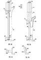
- Figure 2 shows an apparatus for manufacturing the nozzle ring, either the inner or the outer ring, according to an embodiment.
- the manufacturing of the nozzle ring starts with a cylinder 200.
- the cylinder 200 may be a circular cylinder, polygonal cylinder (a polyhedron), a cylinder with an oval circumference or with a freeform circumference.
- the cylinder may also be referred to as a tunnel piece.
- the cylinder has ends 204 and 206, and a sidewall 202 joining the ends 204/206.
- the ends 204/206 are typically open apertures, although in one embodiment one of the ends, the non-modifiable end 206, may also be closed.
- the end 206 would, however, be opened by cutting, for example, before the cylinder 200 is used in a nozzle around a propeller.
- the ends 204 and 206 of the cylinder 200 as shown here are equal in size, the cylinder 200 does not necessarily need to be of this shape. In other words, the ends 204 and 206 may be of a different shape and/or cross-sectional surface from one another.
- the sidewall 202 may be non-linear and/or asymmetric, unlike in Figure 2A . However, for the sake of clarity it is assumed that the cylinder 200 is a circular cylinder open at both ends 204/206.
- the cylinder 200 may be manufactured by roll forming a metal band into an open sidewall 202 and by welding or other wise closing the open sidewall 202, thus forming a cylinder 200 with at least one closure seam 208.
- roll forming the metal band is calendered between at least one roll forming pair, in which the rolls are set so that a sidewall 202 of a desired strength and curvature is obtained.
- the position of the rolls with respect to each other may be such that a desired, possibly curved shape is obtained for the sidewall 202 of the cylinder 200.
- the intended shape is one that allows the leading and trailing ends of the open sidewall 202 to be brought together so that they may be welded or otherwise joined. It is also possible to manufacture the cylinder by bending a plate in a pressing machine.
- the cylinder 200 has only one closure seam.
- An advantage of a single closure seam, such as a welding seam is that the structure becomes significantly more uniform and strong than if the structure had a plural number of welding seams. For this reason one welding seam is aimed at, although it is also possible to use more plates to manufacture the cylinder 200.
- the dimensions of the cylinder 200 may be determined in advance.
- the thickness of the sidewall 202 may be in the order of 10 to 30 mm.
- the height of the sidewall 202 of the cylinder 200 may be in the order of 0.5 to 3 m, for example, and the diameter of the cylinder 200 may be in the order of 2 to 10 m, for example.
- the material the cylinder 200 is manufactured of may be a metal having a sufficient break elongation and strength.
- a cylinder is usually made of structural steel or stainless or acid-resistant steel.
- the apparatus for manufacturing the nozzle ring also comprises a circular mould 220 having a side profile 222 that widens towards one end 226 of the mould.
- the mould 220 is arrangeable to the neck of the end 204 of the cylinder 200, a first end 224 of the mould 220 being towards the interior of the cylinder 200 and a second end 206 of the mould 220 having a cross-sectional surface that is greater than the end 204 of the cylinder 200.
- the mould 220 comprises a first end 224 of a smaller cross-sectional surface, a second end 226 of a greater cross-sectional surface and a side profile 222 that remains between these two ends 224 and 226 and has an outer surface that at least partly widens towards the second end 226, as shown by reference numeral 223.
- the mould 220 has a cross-sectional surface which, when examined in the direction of the side profile 222, grows towards the second end 226, the growing cross-sectional surface of the mould 220 being at least at some point greater than the cross-sectional surface of the end 204 of the cylinder 200.
- the pieces 200/220 may be arranged to each other also in some direction than the one shown in Figure 2A , where the mould 220 is placed on top of the cylinder 200. In other words, the mould 220 may be underneath and the cylinder 200 may be placed on top of the mould 220, or the mould 220 and the cylinder 200 may be arranged to each other on a horizontal plane.
- the ends 224 and 226 do not need to exist in a physical sense.
- the ends may be thought of as virtual ends.
- the end 224 for example, is on the cross-section of the sphere that is arrangeable to the neck of the cylinder 200, the end 226 being the cross-section of the spherical mould that is greater than the cross-section of the end 204.
- ends in the physical sense are not shown.
- the mould 220 may also be referred to as a die, a forming structure, a bulging piece or a press or tension mould. According to an embodiment, the mould 220 may be a circular piece with closed ends 224 and 226 or, as in another embodiment, a circular piece with open ends 224 and 226.
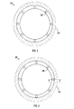
- Figure 5 shows a circular mould 520 according to the latter embodiment.
- Figure 5 is a top view of the mould 520, which comprises a side profile of a specific shape presented with diagonal lines and reference numeral 522.
- the mould 520 may additionally contain at least one connection point 528.
- Each connection point 528 may allow a connecting rod to be connected to the mould 520.
- This at least one connecting rod may connect the mould 520 to a counter piece, which will be described later.
- the connecting point 528 may be just a partial through-hole allowing, nevertheless, a stationary fastening of the connecting rod to the mould 520 or the connecting rod to be taken through the mould 520 without stationary fastening. Stationary fastening in this context means that the fastened parts do not move in relation to one another.
- the mould 220 may be manufactured by casting metal to produce a uniform mould.
- the mould 220 is a nickel aluminium bronze casting.
- the advantage of nickel aluminium bronze is that it is strong and anti-frictional.
- many propellers are made of nickel aluminium bronze, it is advantageous to use the same material for the mould.
- the anti-frictional property of the material is advantageous in the manufacture of the nozzle ring.
- a further aspect having an effect on the strength of the material is that in an embodiment the mould 220 is a uniform cast piece.
- the apparatus for manufacturing the nozzle ring from the cylinder 200 comprises means for forcing the mould 220 into the cylinder 200 (tunnel piece) for a predetermined distance so that the outer surface of the side profile 222 of the mould 220 runs against the inner surface of the cylinder 200, thereby widening at least part of the cylinder 200 to match the widening shape of the side profile 222 of the mould 220, the cylinder 200 thus reaching the shape of the cylinder ring.
- the reached nozzle ring shape may be the shape of the inner surface of the nozzle ring or the shape of the outer surface of the nozzle ring. In other words, the reached nozzle ring may be an inner cylinder or an outer cylinder of the nozzle.
- the manufactured ring may thus be applied both as an outer nozzle ring and an inner nozzle ring.
- the mould 220 may be given a desired shape at the very beginning, and by making the mould 220 enter the cylinder, the mould 220 forces at least part of the cylinder 200 to widen.
- the entire mould 220 runs along the inner surface of the cylinder 200, whereby the entire sidewall 202 of the cylinder 200 widens.
- the shape of the mould 220 is not restricted to that shown in Figure 2A , but different kinds of shapes may be manufactured.
- the purpose of the mould is to widen at least part of the sidewall 202 of the cylinder 200.
- at least part of the outer surface of the side profile 222 of the mould 220 widens non-linearly towards the second end 226 of the mould. Non-linearity is advantageous in order for good propeller energy efficiency to be achieved.
- the outer surface 222 of the side profile may widen exponentially, for example, towards the end 226 of a greater cross-sectional surface in the mould 220.
- the height of the side profile 222 is selected to match the length of the part that is to be modified on the side profile 202 of the cylinder 200. This allows an economical material solution to be obtained, because the mould 220 is precisely of the desired length.
- the obtained nozzle ring may thus be a part of the nozzle 100/120 shown in Figure 1 , for example.
- Figure 2B shows another possible nozzle ring 230.
- the entire sidewall 202 of the nozzle ring 230 in the figure has widened symmetrically at the cylindrical nozzle ring 230 from point 203 to match the non-linear widening of the side profile 222 of the mould 220 (point 223 on the mould).
- thinning of the sidewall 202 may occur. However, this thinning does not markedly impair the strength of the sidewall 202 of the nozzle ring 230 or its applicability to a propeller nozzle.
- the mould 220 is forced into the cylinder 200.
- the forcing comprises compression, pressing or drawing, for example.
- pressing means may comprise a large mass, for example, to be placed on top of the mould end 226 (or the ring of the end 226) to cause the mould 220 to sink inside the cylinder 200 by the force of gravity.
- the cylinder 200 may be on top of hard soil or on a support structure, for example.
- the compression means comprise a at least one high-force press, among other things.
- the press may be a hydraulic press or a screw press, for example.
- the press may be placed on the ring of the ends 226 and 206 and may cause the mould 220 to be forced into the cylinder 200 for a predetermined distance. If the mould 220 and the cylinder 200 are open at their ends, the press may be inside the mould 220 and the cylinder 200. On the other hand, if the mould 220 is closed, the shaft of the press may run outside the mould 220 and the cylinder 200.
- grease is used on the side profile 222 of the mould 220 and/or on the sidewall 202 of the cylinder 200 so that friction between the sidewalls 202 and 222 would be as low as possible. This is advantageous in order to minimize the energy needed for the forcing.
- the grease to be used may be a lubricant, for example.
- the means for forcing the mould 220 into the cylinder 200 for a predetermined distance comprise the counter piece shown in Figure 6 against which the cylinder 200 may be placed.
- the counter piece shown in Figure 6 from above comprises at least one connecting point 602, each one of which may allow the lead-through or fastening of the connecting rod in the counter piece 600.
- the at least one connecting rod may connect the mould 220 to the counter piece.
- the connecting rod may be placed between the counter piece 600 and the mould 220 to connect the counter piece 600 and the mould 220 together.
- the connecting point 602 may be just a partial lead-through enabling, nevertheless, stationary fastening of the connecting rod to the counter piece, or an complete lead-through enabling stationary fastening of the connecting rod to the counter piece 600 or the lead-through of the connecting rod in the counter piece 600 without stationary fastening.
- Stationary fastening in this context means that the fastened pieces do not move in relation to one another.
- Figure 6 also shows a setting base 604 depicted with diagonal lines.
- the counter piece may comprise a counter piece 600 of the setting base 604, the ring of the end 206 of the cylinder 200 setting against the setting protrusion.
- This is illustrated in Figure 4 by a cross-sectional view of an example of two counter pieces 400A and 400B. The cross-sectional view is taken from the point depicted with broken lines in the counter piece of Figure 6 as seen from the direction of the arrows.
- Figures 4A and 4B illustrate counter pieces 400A and 400B of some embodiments.
- the counter pieces 400A and 400B comprise setting bases 404A and 404B and protrusions 401 A and 401 B, the protrusions 401 A and 401 B comprising at least one connecting point 402A and 402B.
- the counter piece 600 is a cylindrical piece having a diameter which is smaller or larger than the diameter of the cylinder 200 to be modified into the nozzle ring 230 to the extent that when the cylinder 200 is placed around or inside the counter piece 600 part of the sidewall 202 of the cylinder 200 sets against the sidewall of the counter piece 600.
- the counter piece 600 may be arranged fixedly in place, thus preventing at the same time the movement of the cylinder 200 which is at least substantially in contact with it. Hence the counter piece 600 produces an effect of supporting the cylinder 200.
- the counter piece is usually made of structural steel using ordinary manufacturing methods applied in an engineering workshop. It is also possible to make the counter piece by casting material of a sufficient strength property. Accordingly, a counter piece of an embodiment is made by casting.
- the manufacturing material may be nickel aluminium bronze.
- Figures 3A and 3B are cross-sectional views of the mould 220 or 520, the cylinder 200 and the counter piece 600, 400A or 400B.
- the figures also show means for forcing the mould 220 into the cylinder 200.
- Figure 3A illustrates an initial situation and Figure 3B a moment where the mould 220 has been forced into the cylinder 200.
- These means for forcing the mould 220 into the cylinder 200 for a predetermined distance comprise in this embodiment at least a connecting rod 300 fastened in a stationary manner either to the mould 220 or the counter piece 600.
- the stationary fastening has been implemented to the counter piece 600 by fastening means 302, which may comprise screws and a nut, for example.
- the connecting rod 300 may be provided with a threading, which is screwed to the counter piece 600 and thus forms a stationary fastening.
- the mould 220 has at least one connecting point 528 allowing the connecting rod 300 to be connected to the mould 220.
- the connection is a lead-through from the mould 220.
- the mould 220 is thus movable in relation to the connecting rod 300. Movability may mean that the mould 220 may move (slide) up and down on the connecting rod 300.
- the means for forcing the mould 220 into the cylinder 200 comprise, according to the embodiment, a hydraulics arrangement 310 fastened to each connecting rod 300 by fastening means 304.
- a hydraulics arrangement 310 fastened to each connecting rod 300 by fastening means 304.
- pressure is supplied to the hydraulics arrangement 310, at least one part of the hydraulics arrangement which is at least indirectly in contact with the mould 220 or the counter piece 300 moves in relation to the connecting rod 300, forcing at the same time the mould 220 towards the interior of the cylinder 200.
- the hydraulics arrangement 310 is at least indirectly (directly or through an intermediate piece) in contact with the mould 220.
- the hydraulics arrangement 310 is of a size that one fastening and pressure supply to the hydraulics arrangement 310 enables the hydraulics arrangement 310 to produce a movement of the mould 220 into the cylinder 200 for the predetermined distance required.
- the hydraulics arrangement 310 is of a size that one fastening and pressure supply to the hydraulics arrangement 310 enables the hydraulics arrangement 310 to cause the mould 220 to enter the cylinder 200 for only a part of the predetermined distance required. In that case a need may arise to detach the hydraulics arrangement 310 from the connecting rod 300, to move the position of the hydraulics arrangement 310 on the connecting rod 300 and to fasten the hydraulics arrangement 310 to a new position on the connecting rod 300. In this new position the hydraulics arrangement 310, when subjected to pressure, is capable of causing the mould 220 to move in relation to the connecting rod 220 towards the interior of the cylinder 200.
- the hydraulics arrangement comprises a cylinder 312 and a piston 314 around the connecting rod 300 and, further, means for producing pressure 316 to the cylinder-piston pair, in which either the cylinder 312 or the piston 314 is at least indirectly in contact with the mould 220 or the counter piece 600.
- the piston 314 of the hydraulics arrangement 310 is fastened with fastening means 304 to the connecting rod 300 in a stationary manner.
- pressure such as oil or compressed air
- pressure generating means 316 such as a valve and a pump
- the produced pressure, such as oil or compressed air, in the cylinder 312 is illustrated by a mesh pattern. Since the piston 314 is fastened to the fastening rod 300 in a stationary manner with fastening means 304, such as a nut, the cylinder 312 moves on the connecting rod 300 and pushes at the same time the mould 220 that is in contact with the cylinder towards the interior of the cylinder 200. Hence, the mould structure 220, which is larger than the cylinder 200, provides the sidewall of the cylinder 200 with the desired nozzle ring shape.
- the hydraulics arrangement 310 is at least indirectly in contact with the counter piece 600, and the connecting rod 300 is fastened to the mould 220 in a stationary manner and to the counter piece 600 through a lead-through only.
- the counter piece 600 may be brought into movement by the hydraulics arrangement 310 by pressing the counter piece 600 and the mould 220 towards each other and, at the same time, into the mould 220.
- the hydraulics arrangement 310, the connecting rod 300 and the mould are detached from the nozzle ring (from the original cylinder 200).
- the cylinder 312 could be fastened to the connecting rod 300 in a stationary manner, the piston 314 being the part of the hydraulics arrangement 310 that would move in relation to the connecting rod 300.
- the hydraulics arrangement 310 is illustrated as being on the side of the mould 220 not provided with the counter piece 600, the hydraulics arrangement 310 could also be placed and fastened between the counter piece 600 and the mould 220. In that case the hydraulics arrangement 310 could have protrusions fastened thereto to connect the hydraulics arrangement 310 either to the counter piece 600 or to the mould 220. Upon pressure supply, the part of the hydraulics arrangement 310 that moves in relation to the connecting rod 300 would draw either the mould 220 or the counter piece 600 towards each other with the protrusions, thus causing the mould 220 to press into the cylinder 200.
- the hydraulics arrangement 310 mentioned above or disclosed in Figure 3 could be provided and fastened also to the side of the counter piece 600.
- a large quantity of cylinder-piston pairs is provided for forming sets of cylinder-piston pairs of a specific size, the sets being controlled by one pump.
- a set may comprise six cylinder-piston pairs, for example.
- one pump allows a large quantity of cylinder-piston pairs to be controlled.
- An advantage of controlling only a sub-quantity of all cylinder-piston pairs with one pump is that the requirements set for the pumps with regard to production of pressure oil are less strict than if all cylinder-piston pairs were controlled with one pump.
- a set of smaller pumps is also more economical to purchase than a single, large pump that is subject to high requirements.
- each cylinder-piston pair may be controlled by a separate pump, or all cylinder-piston pairs may be controlled by pressure produced with a single pump.
- the hydraulics arrangement provides a force of several dozens of tons, for example 60 tons, the force being applied to forcing the mould 220 into the cylinder 200. Because of the requirement for high force production, it is advantageous to use a plurality of hydraulics arrangements 310.
- the apparatus is provided with eight connecting rods, each one of which has a cylinder-piston pair. However, all the connecting rods do not need to be provided with a hydraulics arrangement, but a connecting rod may be left without one. Since the apparatus is used for drawing, in a manner of speaking, the counter piece 600 and the mould 220 towards each other, the method in which the apparatus is used may be referred to as a deep draw method.
- Figure 8 shows in greater detail what is meant by the inner and outer ring of the nozzle.
- Figures 8A to 8C show different nozzles consisting of an inner ring 202A, 202B and 202C and an outer ring 800A, 800B and 800C.
- the inner and outer rings are between the ends 204 and 206.
- the manufacturing of the inner rings 202A and 202C of Figures 8A and 8C has been disclosed earlier in this specification, the manufacturing methods and apparatuses of the different embodiments may be used for producing also an inner ring 202B of Figure 8B .
- the manufacturing methods and apparatuses of the different embodiments may be used for producing outer ring shapes 800A, 800B and 800C of Figures 8A, 8B and 8C , respectively.
- a feature common to the structure of the rings 202A to 202C and 800A to 800C is that each of them has at least partly widening side profile. This widening may be achieved by the manufacturing methods and apparatuses of the different embodiments.
- the different manufacturing methods and embodiments are not restricted to these shapes, but also nozzle rings of other shapes may be manufactured, provided that the side profile of the ring has at least partly widening shape.
- the manufactured inner and outer rings may be joined together, as shown in Figures 8A to 8C .
- This may be performed by welding, for example.
- Any hollow space between the welding points may be strengthened, if desired, by adding steel plates, for example, to support the structure.
- the nozzle may be made of a single ring manufactured according to the different embodiments.
- the sidewall of the nozzle may be reinforced by providing it with predetermined additional structures to obtain the final nozzle shape. Nozzles thus obtained may have a smooth inner surface, which is particularly advantageous in terms of flow.
- Figure 7 illustrates a method for forming the nozzle ring from a cylinder.
- the method starts at step 700.
- a circular mould is formed, the mould having a side profile that widens towards one end thereof and the mould being placeable to the neck of the cylinder with a first end of the mould oriented towards the inner space of the cylinder and a second end of the mould having a cross-sectional surface greater than the cylinder end in question.
- the mould is forced into the cylinder for a predetermined distance, the outer surface of the side profile of mould running against the inner surface of the cylinder and thus widens at least part of the cylinder to match the widening shape of the side profile of the mould, the cylinder thus reaching the shape of the nozzle ring.
- the method ends at step 706.
- a nozzle ring manufactured according to this method may be used in ships or airplanes, for example.
- the method and apparatus have a number of advantages.
- the manufacturing of the nozzle does not require forging or heating of the material.
- the nozzle ring is strong because, according to an embodiment, it has only one closure seam.
- the nozzle ring has an optimal shape. Because of the material selected, there is a slide effect between the mould and the cylinder that reduces the friction between them. Rings of different sizes may be easily manufactured by changing the diameters of the mould and the cylinder. Moulds of different sizes may be manufactured by changing the width parameters of the mould.
Landscapes
- Engineering & Computer Science (AREA)
- Mechanical Engineering (AREA)
- Chemical & Material Sciences (AREA)
- Combustion & Propulsion (AREA)
- Ocean & Marine Engineering (AREA)
- Aviation & Aerospace Engineering (AREA)
- Pistons, Piston Rings, And Cylinders (AREA)
- Moulds For Moulding Plastics Or The Like (AREA)
- Shaping Metal By Deep-Drawing, Or The Like (AREA)
Abstract
Description
- The invention relates to a method and apparatus for manufacturing a propeller nozzle ring.
- It is known in the art to manufacture a nozzle by using a plurality, for example 6 to 10, metal plates or sectors which are pressed into a mould and welded together. Before being brought together, these sectors have been processed so that, when assembled, they form a substantially ring-like structure having in the incoming water direction an open end having a cross-sectional surface that is slightly larger than the cross-sectional surface of the open end in the outgoing water direction.
- Problems with the above arrangement include questionable nozzle strength and possible unevenness of the nozzle, due to numerous welding seams and sectors, and complicated manufacturing of the nozzle. Because of the manufacturing method, the nozzle is also subjected to deformations, which make the shape of the nozzle non-ideal. This is disadvantageous to the outer appearance of the nozzle and to water flow in the nozzle.
- The invention aims at providing an improved method and apparatus for manufacturing a propeller nozzle ring.
- As an aspect of the invention, a method according to independent claim 1 is disclosed.
- As an aspect of the invention, a device according to independent claim 7 is disclosed.
- The invention allows a strong nozzle ring with a smooth surface to be provided. The nozzle ring has good symmetry characteristics. Unlike prior art solutions, the invention provides a nozzle with an optimal shape. Moreover, the manufacturing method and apparatus are cost-effective.
- In the following, the invention will be disclosed in greater detail with reference to preferred embodiments and the accompanying drawings, in which
-
Figures 1A and 1B illustrate examples of nozzle shapes; -
Figures 2A and 2B illustrate apparatuses for forming a nozzle ring according to some embodiments; -
Figures 3A and 3B illustrate apparatuses for forming a nozzle ring according to some embodiments; -
Figures 4A and 4B are cross-sectional views of examples of counter pieces; -
Figure 5 is a top view of a mould according to an embodiment; -
Figure 6 is a top view of a counter piece according to an embodiment; -
Figure 7 illustrates a method for manufacturing a nozzle ring according to an embodiment; and -
Figures 8A, 8B and 8C illustrate examples of nozzle shapes. - Although the different embodiments may be implemented to provide nozzles for example for ships, aircrafts and submarines, the specification below relates to a nozzle used in a ship. Nevertheless, this does not restrict the scope of protection to ship nozzles alone, but also nozzles used in the above-mentioned other vehicles and vessels are included. Moreover, a nozzle ring produced according to the different embodiments may also be utilized in other apparatuses, such as wind generators.
- It is known in the art to provide propellers with what is known as a nozzle, i.e. a propeller ring, which substantially surrounds the propeller from the direction of the blade tips. Accordingly, such propellers may be called nozzle propellers or ducted propellers, as distinct from open propellers. The purpose of the nozzle in ships is to guide the water mass to the propeller. For this reason the nozzle is typically slightly wider in the incoming water direction than in the outgoing water direction, and is an open frustoconical shape, for example, at both ends. This forces the flow field around the propeller into a specific shape. However, as a result, the nozzle is subjected to a high pressure because the area it collects water from is larger than the one behind the propeller, where water is released. Similarly, in aircrafts a nozzle may guide the flow of air. Moreover, the nozzle may protect the propeller against external factors.
- Ships are typically provided with at least one propeller below the water surface to create a force that moves the ship to a desired direction. According to a propeller's operating principles, its rotating motion is converted into thrust power. The propeller consists of a shaft with two or more blades substantially perpendicularly attached thereto. This is why propellers are also referred to as wheels. Particularly in ships, such as ocean liners, it is known to use a fixed propeller having a shaft that is an extension of a propeller transmission shaft installed to the lower part of the ship in the longitudinal direction thereof. In that case the propeller end is typically provided with a rudder, and by turning the rudder, the ship may be driven to the desired direction. Today it is also known to use turning propellers. A specific manufacturer produces turning propellers under the name Azipod®. This type of propeller does not necessarily need a rudder, because it may be turned. This is possible because a turning propeller is typically mounted to a transmission and steering shaft that is substantially perpendicular to the longitudinal direction of the ship. When this vertically mounted shaft is rotated about its longitudinal axis, the propeller turns to the desired direction. In addition, this allows the ship to be steered substantially in the lateral direction of the ship. This is important in a harbour area, for example. On the other hand, a fixed propeller may be similarly at the end of a vertical shaft.
- A nozzle to be used for a propeller may comprise an inner ring and an outer ring, such as an inner and an outer cylinder (or a cylindrical piece) or an inner and an outer cone (or a conical piece), and, when assembled together, these may form a sidewall of the nozzle. The inner ring may at least partly determine the shape of the nozzle's inner surface, and the outer ring may at least partly determine the shape of nozzle's outer surface. A nozzle ring, either an inner ring or outer ring, according to the different embodiments may be utilized both in fixed and turning ducted propellers. Ships may be provided with a plural number of additional propellers, all of which may be provided with a nozzle having a nozzle ring manufactured by a method and apparatus of the different embodiments.
-
Figures 1A and 1B show anozzle 100/120 around a propeller, or wheel, 108. Thenozzle 100 may also be referred to as the propeller ring. Thenozzle 100/120 is open at bothends water 110 to flow through thenozzle 100/120. Typically thenozzle 100/120 comprises two rings, an inner and an outer ring, facing each other and thus forming the inner and outer surfaces of thenozzle 100/120 between theends end 104 of thenozzle 100/120 has typically a larger cross-sectional area than the other 102 to allow thenozzle 100/120 to receive a larger water mass than it would otherwise do. Depending on the shape of the inner surface of thenozzle 100/120, this causes either a higher flow rate or a higher pressure on the propeller. InFigure 1A thenozzle 100 has a frustoconical shape and thus causes a higher pressure on the propeller, thereby slowing down the water flow rate. This is advantageous for example when the sound of a running engine is to be attenuated. InFigure 1B thenozzle 120 is non-linearly widening, thus increasing the flow rate to the propeller, which in turn increases propeller efficiency. It should also be noted thatFigure 1 only shows two examples of the nozzle, the different embodiments not being restricted to these, but in addition to these two nozzle shapes, nozzles of different shapes may be manufactured. -
Figure 2 shows an apparatus for manufacturing the nozzle ring, either the inner or the outer ring, according to an embodiment. The manufacturing of the nozzle ring starts with acylinder 200. InFigure 2A thecylinder 200 may be a circular cylinder, polygonal cylinder (a polyhedron), a cylinder with an oval circumference or with a freeform circumference. In this context the cylinder may also be referred to as a tunnel piece. The cylinder has ends 204 and 206, and asidewall 202 joining theends 204/206. The ends 204/206 are typically open apertures, although in one embodiment one of the ends, thenon-modifiable end 206, may also be closed. In that case theend 206 would, however, be opened by cutting, for example, before thecylinder 200 is used in a nozzle around a propeller. Moreover, although theends cylinder 200 as shown here are equal in size, thecylinder 200 does not necessarily need to be of this shape. In other words, theends sidewall 202 may be non-linear and/or asymmetric, unlike inFigure 2A . However, for the sake of clarity it is assumed that thecylinder 200 is a circular cylinder open at both ends 204/206. - The
cylinder 200 may be manufactured by roll forming a metal band into anopen sidewall 202 and by welding or other wise closing theopen sidewall 202, thus forming acylinder 200 with at least oneclosure seam 208. In roll forming the metal band is calendered between at least one roll forming pair, in which the rolls are set so that asidewall 202 of a desired strength and curvature is obtained. The position of the rolls with respect to each other may be such that a desired, possibly curved shape is obtained for thesidewall 202 of thecylinder 200. The intended shape is one that allows the leading and trailing ends of theopen sidewall 202 to be brought together so that they may be welded or otherwise joined. It is also possible to manufacture the cylinder by bending a plate in a pressing machine. According to an embodiment, thecylinder 200 has only one closure seam. An advantage of a single closure seam, such as a welding seam, is that the structure becomes significantly more uniform and strong than if the structure had a plural number of welding seams. For this reason one welding seam is aimed at, although it is also possible to use more plates to manufacture thecylinder 200. - The dimensions of the
cylinder 200 may be determined in advance. For example, the thickness of thesidewall 202 may be in the order of 10 to 30 mm. The height of thesidewall 202 of thecylinder 200 may be in the order of 0.5 to 3 m, for example, and the diameter of thecylinder 200 may be in the order of 2 to 10 m, for example. - The material the
cylinder 200 is manufactured of may be a metal having a sufficient break elongation and strength. A cylinder is usually made of structural steel or stainless or acid-resistant steel. - According to an embodiment, the apparatus for manufacturing the nozzle ring also comprises a
circular mould 220 having aside profile 222 that widens towards oneend 226 of the mould. Themould 220 is arrangeable to the neck of theend 204 of thecylinder 200, afirst end 224 of themould 220 being towards the interior of thecylinder 200 and asecond end 206 of themould 220 having a cross-sectional surface that is greater than theend 204 of thecylinder 200. According to an embodiment, themould 220 comprises afirst end 224 of a smaller cross-sectional surface, asecond end 226 of a greater cross-sectional surface and aside profile 222 that remains between these twoends second end 226, as shown byreference numeral 223. In other words, themould 220 has a cross-sectional surface which, when examined in the direction of theside profile 222, grows towards thesecond end 226, the growing cross-sectional surface of themould 220 being at least at some point greater than the cross-sectional surface of theend 204 of thecylinder 200. This ensures that themould 220 stays on the neck of theend 204 of thecylinder 200 without at least entirely sinking inside thecylinder 200. Thepieces 200/220 may be arranged to each other also in some direction than the one shown inFigure 2A , where themould 220 is placed on top of thecylinder 200. In other words, themould 220 may be underneath and thecylinder 200 may be placed on top of themould 220, or themould 220 and thecylinder 200 may be arranged to each other on a horizontal plane. - However, the
ends mould 220 is spherical, the ends may be thought of as virtual ends. In that case theend 224, for example, is on the cross-section of the sphere that is arrangeable to the neck of thecylinder 200, theend 226 being the cross-section of the spherical mould that is greater than the cross-section of theend 204. The same applies to other figures where ends in the physical sense are not shown. - The
mould 220 may also be referred to as a die, a forming structure, a bulging piece or a press or tension mould. According to an embodiment, themould 220 may be a circular piece withclosed ends open ends -
Figure 5 shows acircular mould 520 according to the latter embodiment.Figure 5 is a top view of themould 520, which comprises a side profile of a specific shape presented with diagonal lines andreference numeral 522. Themould 520 may additionally contain at least oneconnection point 528. Eachconnection point 528 may allow a connecting rod to be connected to themould 520. This at least one connecting rod may connect themould 520 to a counter piece, which will be described later. The connectingpoint 528 may be just a partial through-hole allowing, nevertheless, a stationary fastening of the connecting rod to themould 520 or the connecting rod to be taken through themould 520 without stationary fastening. Stationary fastening in this context means that the fastened parts do not move in relation to one another. - The
mould 220 may be manufactured by casting metal to produce a uniform mould. According to an embodiment, themould 220 is a nickel aluminium bronze casting. The advantage of nickel aluminium bronze is that it is strong and anti-frictional. Moreover, since many propellers are made of nickel aluminium bronze, it is advantageous to use the same material for the mould. The anti-frictional property of the material is advantageous in the manufacture of the nozzle ring. A further aspect having an effect on the strength of the material is that in an embodiment themould 220 is a uniform cast piece. - In addition, the apparatus for manufacturing the nozzle ring from the
cylinder 200 comprises means for forcing themould 220 into the cylinder 200 (tunnel piece) for a predetermined distance so that the outer surface of theside profile 222 of themould 220 runs against the inner surface of thecylinder 200, thereby widening at least part of thecylinder 200 to match the widening shape of theside profile 222 of themould 220, thecylinder 200 thus reaching the shape of the cylinder ring. The reached nozzle ring shape may be the shape of the inner surface of the nozzle ring or the shape of the outer surface of the nozzle ring. In other words, the reached nozzle ring may be an inner cylinder or an outer cylinder of the nozzle. According to the embodiments, the manufactured ring may thus be applied both as an outer nozzle ring and an inner nozzle ring. After the forcing themould 220 is detached from thecylinder 200. Themould 220 may be given a desired shape at the very beginning, and by making themould 220 enter the cylinder, themould 220 forces at least part of thecylinder 200 to widen. According to an embodiment, theentire mould 220 runs along the inner surface of thecylinder 200, whereby theentire sidewall 202 of thecylinder 200 widens. - The shape of the
mould 220 is not restricted to that shown inFigure 2A , but different kinds of shapes may be manufactured. The purpose of the mould is to widen at least part of thesidewall 202 of thecylinder 200. According to an embodiment, at least part of the outer surface of theside profile 222 of themould 220 widens non-linearly towards thesecond end 226 of the mould. Non-linearity is advantageous in order for good propeller energy efficiency to be achieved. Theouter surface 222 of the side profile may widen exponentially, for example, towards theend 226 of a greater cross-sectional surface in themould 220. According to an embodiment, the height of theside profile 222 is selected to match the length of the part that is to be modified on theside profile 202 of thecylinder 200. This allows an economical material solution to be obtained, because themould 220 is precisely of the desired length. - The obtained nozzle ring may thus be a part of the
nozzle 100/120 shown inFigure 1 , for example.Figure 2B shows anotherpossible nozzle ring 230. Theentire sidewall 202 of thenozzle ring 230 in the figure has widened symmetrically at thecylindrical nozzle ring 230 frompoint 203 to match the non-linear widening of theside profile 222 of the mould 220 (point 223 on the mould). As thecylinder 200 widens to match the desired shape of thenozzle ring 230, thinning of thesidewall 202 may occur. However, this thinning does not markedly impair the strength of thesidewall 202 of thenozzle ring 230 or its applicability to a propeller nozzle. - As stated, the
mould 220 is forced into thecylinder 200. The forcing comprises compression, pressing or drawing, for example. According to an embodiment, pressing means may comprise a large mass, for example, to be placed on top of the mould end 226 (or the ring of the end 226) to cause themould 220 to sink inside thecylinder 200 by the force of gravity. In that case thecylinder 200 may be on top of hard soil or on a support structure, for example. According to another embodiment, the compression means comprise a at least one high-force press, among other things. The press may be a hydraulic press or a screw press, for example. The press may be placed on the ring of theends mould 220 to be forced into thecylinder 200 for a predetermined distance. If themould 220 and thecylinder 200 are open at their ends, the press may be inside themould 220 and thecylinder 200. On the other hand, if themould 220 is closed, the shaft of the press may run outside themould 220 and thecylinder 200. - According to an embodiment, grease is used on the
side profile 222 of themould 220 and/or on thesidewall 202 of thecylinder 200 so that friction between thesidewalls - According to an embodiment, the means for forcing the
mould 220 into thecylinder 200 for a predetermined distance comprise the counter piece shown inFigure 6 against which thecylinder 200 may be placed. The counter piece shown inFigure 6 from above comprises at least one connectingpoint 602, each one of which may allow the lead-through or fastening of the connecting rod in thecounter piece 600. The at least one connecting rod may connect themould 220 to the counter piece. In other words, the connecting rod may be placed between thecounter piece 600 and themould 220 to connect thecounter piece 600 and themould 220 together. The connectingpoint 602 may be just a partial lead-through enabling, nevertheless, stationary fastening of the connecting rod to the counter piece, or an complete lead-through enabling stationary fastening of the connecting rod to thecounter piece 600 or the lead-through of the connecting rod in thecounter piece 600 without stationary fastening. Stationary fastening in this context means that the fastened pieces do not move in relation to one another. -
Figure 6 also shows asetting base 604 depicted with diagonal lines. Hence the counter piece may comprise acounter piece 600 of thesetting base 604, the ring of theend 206 of thecylinder 200 setting against the setting protrusion. This is illustrated inFigure 4 by a cross-sectional view of an example of twocounter pieces Figure 6 as seen from the direction of the arrows.Figures 4A and 4B illustratecounter pieces counter pieces bases protrusions protrusions point - According to an embodiment, the
counter piece 600 is a cylindrical piece having a diameter which is smaller or larger than the diameter of thecylinder 200 to be modified into thenozzle ring 230 to the extent that when thecylinder 200 is placed around or inside thecounter piece 600 part of thesidewall 202 of thecylinder 200 sets against the sidewall of thecounter piece 600. Thecounter piece 600 may be arranged fixedly in place, thus preventing at the same time the movement of thecylinder 200 which is at least substantially in contact with it. Hence thecounter piece 600 produces an effect of supporting thecylinder 200. - The counter piece is usually made of structural steel using ordinary manufacturing methods applied in an engineering workshop. It is also possible to make the counter piece by casting material of a sufficient strength property. Accordingly, a counter piece of an embodiment is made by casting. The manufacturing material may be nickel aluminium bronze.
- Let us examine
Figures 3A and 3B , which are cross-sectional views of themould cylinder 200 and thecounter piece mould 220 into thecylinder 200.Figure 3A illustrates an initial situation andFigure 3B a moment where themould 220 has been forced into thecylinder 200. These means for forcing themould 220 into thecylinder 200 for a predetermined distance comprise in this embodiment at least a connectingrod 300 fastened in a stationary manner either to themould 220 or thecounter piece 600. In the example ofFigure 3 , the stationary fastening has been implemented to thecounter piece 600 by fastening means 302, which may comprise screws and a nut, for example. If a counter piece ofFigure 4B is concerned, the connectingrod 300 may be provided with a threading, which is screwed to thecounter piece 600 and thus forms a stationary fastening. - According to an embodiment, the
mould 220 has at least one connectingpoint 528 allowing the connectingrod 300 to be connected to themould 220. In this embodiment the connection is a lead-through from themould 220. Themould 220 is thus movable in relation to the connectingrod 300. Movability may mean that themould 220 may move (slide) up and down on the connectingrod 300. - In addition, the means for forcing the
mould 220 into thecylinder 200 comprise, according to the embodiment, a hydraulics arrangement 310 fastened to each connectingrod 300 by fastening means 304. When pressure is supplied to the hydraulics arrangement 310, at least one part of the hydraulics arrangement which is at least indirectly in contact with themould 220 or thecounter piece 300 moves in relation to the connectingrod 300, forcing at the same time themould 220 towards the interior of thecylinder 200. In this example the hydraulics arrangement 310 is at least indirectly (directly or through an intermediate piece) in contact with themould 220. Hence, when pressure is produced into the hydraulics arrangement 310, a specific part of the hydraulics arrangement 310 moves in relation to the connectingrod 300 pressing at the same time themould 220 towards thecylinder 200, as shown inFigure 3B . When themould 220 is pressed into thecylinder 200, the side profile of thecylinder 200 widens at 203 to match the profile of the outer surface of the mould. - According to an embodiment, the hydraulics arrangement 310 is of a size that one fastening and pressure supply to the hydraulics arrangement 310 enables the hydraulics arrangement 310 to produce a movement of the
mould 220 into thecylinder 200 for the predetermined distance required. According to another embodiment, the hydraulics arrangement 310 is of a size that one fastening and pressure supply to the hydraulics arrangement 310 enables the hydraulics arrangement 310 to cause themould 220 to enter thecylinder 200 for only a part of the predetermined distance required. In that case a need may arise to detach the hydraulics arrangement 310 from the connectingrod 300, to move the position of the hydraulics arrangement 310 on the connectingrod 300 and to fasten the hydraulics arrangement 310 to a new position on the connectingrod 300. In this new position the hydraulics arrangement 310, when subjected to pressure, is capable of causing themould 220 to move in relation to the connectingrod 220 towards the interior of thecylinder 200. - According to an embodiment, the hydraulics arrangement comprises a
cylinder 312 and apiston 314 around the connectingrod 300 and, further, means for producingpressure 316 to the cylinder-piston pair, in which either thecylinder 312 or thepiston 314 is at least indirectly in contact with themould 220 or thecounter piece 600. In the example ofFigure 3 , thepiston 314 of the hydraulics arrangement 310 is fastened with fastening means 304 to the connectingrod 300 in a stationary manner. When pressure, such as oil or compressed air, is supplied to the cylinder-piston pair ofFigure 3A through pressure generating means 316, such as a valve and a pump, thepiston 314 is pushed out of thecylinder 312. The produced pressure, such as oil or compressed air, in thecylinder 312 is illustrated by a mesh pattern. Since thepiston 314 is fastened to thefastening rod 300 in a stationary manner with fastening means 304, such as a nut, thecylinder 312 moves on the connectingrod 300 and pushes at the same time themould 220 that is in contact with the cylinder towards the interior of thecylinder 200. Hence, themould structure 220, which is larger than thecylinder 200, provides the sidewall of thecylinder 200 with the desired nozzle ring shape. - According to another embodiment, the hydraulics arrangement 310 is at least indirectly in contact with the
counter piece 600, and the connectingrod 300 is fastened to themould 220 in a stationary manner and to thecounter piece 600 through a lead-through only. This means that thecounter piece 600 may be brought into movement by the hydraulics arrangement 310 by pressing thecounter piece 600 and themould 220 towards each other and, at the same time, into themould 220. Finally the hydraulics arrangement 310, the connectingrod 300 and the mould are detached from the nozzle ring (from the original cylinder 200). - Instead of the hydraulics arrangement 310 and the
piston 314, thecylinder 312 could be fastened to the connectingrod 300 in a stationary manner, thepiston 314 being the part of the hydraulics arrangement 310 that would move in relation to the connectingrod 300. - Although in
Figure 3 the hydraulics arrangement 310 is illustrated as being on the side of themould 220 not provided with thecounter piece 600, the hydraulics arrangement 310 could also be placed and fastened between thecounter piece 600 and themould 220. In that case the hydraulics arrangement 310 could have protrusions fastened thereto to connect the hydraulics arrangement 310 either to thecounter piece 600 or to themould 220. Upon pressure supply, the part of the hydraulics arrangement 310 that moves in relation to the connectingrod 300 would draw either themould 220 or thecounter piece 600 towards each other with the protrusions, thus causing themould 220 to press into thecylinder 200. Alternatively, the hydraulics arrangement 310 mentioned above or disclosed inFigure 3 could be provided and fastened also to the side of thecounter piece 600. - According to an embodiment, a large quantity of cylinder-piston pairs is provided for forming sets of cylinder-piston pairs of a specific size, the sets being controlled by one pump. A set may comprise six cylinder-piston pairs, for example. Thus, one pump allows a large quantity of cylinder-piston pairs to be controlled. An advantage of controlling only a sub-quantity of all cylinder-piston pairs with one pump is that the requirements set for the pumps with regard to production of pressure oil are less strict than if all cylinder-piston pairs were controlled with one pump. A set of smaller pumps is also more economical to purchase than a single, large pump that is subject to high requirements. Moreover, risks of malfunction of the apparatus and any repair costs are smaller for an apparatus in which multiple pumps with relatively loose requirements are used. However, the different embodiments are not restricted to this, but each cylinder-piston pair may be controlled by a separate pump, or all cylinder-piston pairs may be controlled by pressure produced with a single pump.
- According to an embodiment, the hydraulics arrangement provides a force of several dozens of tons, for example 60 tons, the force being applied to forcing the
mould 220 into thecylinder 200. Because of the requirement for high force production, it is advantageous to use a plurality of hydraulics arrangements 310. According to an embodiment, as shown inFigures 5 and 6 , the apparatus is provided with eight connecting rods, each one of which has a cylinder-piston pair. However, all the connecting rods do not need to be provided with a hydraulics arrangement, but a connecting rod may be left without one. Since the apparatus is used for drawing, in a manner of speaking, thecounter piece 600 and themould 220 towards each other, the method in which the apparatus is used may be referred to as a deep draw method. - As stated earlier, the different embodiments allow the manufacturing method to be utilized in the manufacture of both the nozzle inner ring and the nozzle outer ring.
Figure 8 shows in greater detail what is meant by the inner and outer ring of the nozzle.Figures 8A to 8C show different nozzles consisting of aninner ring outer ring ends inner rings 202A and 202C ofFigures 8A and 8C has been disclosed earlier in this specification, the manufacturing methods and apparatuses of the different embodiments may be used for producing also aninner ring 202B ofFigure 8B . In addition, the manufacturing methods and apparatuses of the different embodiments may be used for producing outer ring shapes 800A, 800B and 800C ofFigures 8A, 8B and 8C , respectively. A feature common to the structure of therings 202A to 202C and 800A to 800C is that each of them has at least partly widening side profile. This widening may be achieved by the manufacturing methods and apparatuses of the different embodiments. However, the different manufacturing methods and embodiments are not restricted to these shapes, but also nozzle rings of other shapes may be manufactured, provided that the side profile of the ring has at least partly widening shape. - In the end, the manufactured inner and outer rings may be joined together, as shown in
Figures 8A to 8C . This may be performed by welding, for example. Any hollow space between the welding points may be strengthened, if desired, by adding steel plates, for example, to support the structure. - On the other hand, the nozzle may be made of a single ring manufactured according to the different embodiments. In addition, the sidewall of the nozzle may be reinforced by providing it with predetermined additional structures to obtain the final nozzle shape. Nozzles thus obtained may have a smooth inner surface, which is particularly advantageous in terms of flow.
-
Figure 7 illustrates a method for forming the nozzle ring from a cylinder. The method starts atstep 700. In step 702 a circular mould is formed, the mould having a side profile that widens towards one end thereof and the mould being placeable to the neck of the cylinder with a first end of the mould oriented towards the inner space of the cylinder and a second end of the mould having a cross-sectional surface greater than the cylinder end in question. Instep 704 the mould is forced into the cylinder for a predetermined distance, the outer surface of the side profile of mould running against the inner surface of the cylinder and thus widens at least part of the cylinder to match the widening shape of the side profile of the mould, the cylinder thus reaching the shape of the nozzle ring. The method ends atstep 706. - A nozzle ring manufactured according to this method may be used in ships or airplanes, for example. The method and apparatus have a number of advantages. The manufacturing of the nozzle does not require forging or heating of the material. In addition, the nozzle ring is strong because, according to an embodiment, it has only one closure seam. The nozzle ring has an optimal shape. Because of the material selected, there is a slide effect between the mould and the cylinder that reduces the friction between them. Rings of different sizes may be easily manufactured by changing the diameters of the mould and the cylinder. Moulds of different sizes may be manufactured by changing the width parameters of the mould.
- A person skilled in the art will find it apparent that as technology advances, the basic idea of the invention may be implemented in various ways. The invention and its embodiments are therefore not restricted to the above examples, but may vary within the scope of the claims.
Claims (10)
- A method for manufacturing a propeller nozzle ring (230), characterized by comprising the steps of
forming a circular mould (220) having a side profile (222) that widens towards one end (226) of the mould (220), the mould (220) being arrangeable to the neck of an end (204) of a cylinder (200) so that a first end (224) of the mould (220) is towards the interior of the cylinder (200) and a second end (226) of the mould (220) has a cross-sectional surface greater than the end (204) in question of the cylinder (200); and
forcing the mould (220) into the cylinder (200) for a predetermined distance so that the outer surface of the side profile (222) of the mould (220) runs against the inner surface of the cylinder (200), thereby widening at least part of the cylinder (200) to match the widening shape of the side profile (222) of the mould (220), the cylinder (200) thus reaching the shape of the nozzle ring (230). - A method according to claim 1, characterized by further comprising the steps of
forming a cylinder (200) by roll forming a metal band into an open side profile (222); and
welding the open side profile (222) to close it and to thereby form a cylinder (200) with one closure seam (208). - A method according to any one of the preceding claims, characterized in that at least part of the outer surface of the side profile (222) of the mould (220) is widens non-linearly towards the second end (226) of the mould (220) and the height of the side profile (222) is selected to match the length of the part to be modified of the sidewall (202) of the cylinder (200).
- A method according to any one of the preceding claims, characterized by further comprising the steps of
placing the cylinder (200) against the counter piece (600); and placing at least one connecting rod (300) between the counter piece (600) and the mould (220), thus connecting the counter piece (600) and the mould (220) to each other, and fastening the connecting rod (300) in a stationary manner either to the mould (220) or the counter piece (600);
fastening a hydraulics arrangement (310) to each connecting rod (300) by fastening means (302);
supplying pressure to the hydraulics arrangement (310), whereby at least one part of the hydraulics arrangement (310) that is at least indirectly in contact with the mould (220) or the counter piece (600) moves in relation to the connecting rod (300), forcing at the same time the mould (220) towards the interior of the cylinder (200). - A method according to any one of the preceding claims, characterized by further comprising the step of
casting a uniform mould (220) of nickel aluminium bronze. - A water-craft, characterized in that a nozzle ring (230) manufactured according to any one of the preceding claims 1 to 5 is used in it.
- An apparatus for manufacturing a propeller nozzle ring (230), characterized in that the apparatus comprises
a circular mould (220) having a side profile (222) that widens towards one end (226) of the mould (220), the mould (220) being arrangeable to the neck of an end (204) of a cylinder (200) so that a first end (224) of the mould (220) is towards the interior of the cylinder (200) and a second end (226) of the mould (220) has a cross-sectional surface greater than the end (204) in question of the cylinder (200); and
means for forcing the mould (220) into the cylinder (200) for a predetermined distance so that the outer surface of the side profile (222) of the mould (220) runs against the inner surface of the cylinder (200) and thus widens at least part of the cylinder (200) to match the widening shape of the side profile (222) of the mould (220), the cylinder (200) thus reaching the shape of the nozzle ring (230). - An apparatus according to claim 7, characterized in that at least part of the outer surface of the side profile (222) of the mould (220) widens towards the second end (226) of the mould (220) and the height of the side profile (222) is selected to match the length of the part to be modified of the sidewall (202) of the cylinder (200).
- An apparatus according to any one of claims 7 to 8, characterized in that the means for forcing the mould (220) inside the cylinder (200) comprise
a counter piece (600) against which the cylinder (200) is placeable;
at least one connecting rod (300) placeable between the counter piece (600) and the mould (220) to connect the counter piece (600) and the mould (220) to each other, the connecting rod (300) being fastened in a stationary manner either to the mould (220) or the counter piece (600); and
a hydraulics arrangement (310) fastened to each connecting rod (300) by fastening means (302), supply of pressure to the hydraulics arrangement causing at least one part of the hydraulics arrangement (310) that is in at least indirect contact with the mould (220) or the counter piece (600) to move in relation to the connecting rod (300), forcing at the same time the mould (220) towards the interior of the cylinder (200). - An apparatus according to any one of claims 8 to 9, characterized in that the mould (220) is uniformly cast in nickel aluminium bronze.
Applications Claiming Priority (1)
| Application Number | Priority Date | Filing Date | Title |
|---|---|---|---|
| FI20105217A FI124155B (en) | 2010-03-05 | 2010-03-05 | Manufacturing method and apparatus for a propeller nozzle |
Publications (2)
| Publication Number | Publication Date |
|---|---|
| EP2363218A2 true EP2363218A2 (en) | 2011-09-07 |
| EP2363218A3 EP2363218A3 (en) | 2016-11-30 |
Family
ID=42074334
Family Applications (1)
| Application Number | Title | Priority Date | Filing Date |
|---|---|---|---|
| EP11156338.3A Withdrawn EP2363218A3 (en) | 2010-03-05 | 2011-03-01 | Method and apparatus for manufacturing propeller nozzle ring |
Country Status (4)
| Country | Link |
|---|---|
| EP (1) | EP2363218A3 (en) |
| JP (1) | JP2011184042A (en) |
| KR (1) | KR101887568B1 (en) |
| FI (1) | FI124155B (en) |
Cited By (2)
| Publication number | Priority date | Publication date | Assignee | Title |
|---|---|---|---|---|
| ES2384710A1 (en) * | 2009-06-04 | 2012-07-11 | Universidad De Vigo | CONFORMING MACHINE OF CLOSED SHEETS. |
| CN111169615A (en) * | 2020-01-09 | 2020-05-19 | 北京玻钢院复合材料有限公司 | Composite material conduit of propeller and preparation method thereof |
Family Cites Families (16)
| Publication number | Priority date | Publication date | Assignee | Title |
|---|---|---|---|---|
| GB1070743A (en) * | 1964-04-23 | 1967-06-01 | Burness Corlett & Partners Ltd | Improvements in or relating to propulsion nozzles for ships |
| JPS50128322U (en) * | 1974-04-06 | 1975-10-21 | ||
| JPS5180669A (en) * | 1975-01-11 | 1976-07-14 | Kokan Giken Kk | KANTANNIFURANJIOKEISEISURUHOHO OYOBI SOCHI |
| JPS5336298U (en) * | 1976-09-01 | 1978-03-30 | ||
| JPS5838323U (en) * | 1981-09-04 | 1983-03-12 | 坂田 治夫 | Bell mouth semi-finished product molding equipment |
| JPH01104419A (en) * | 1986-04-01 | 1989-04-21 | Sumitomo Metal Ind Ltd | Device for straightening deformation of pipe end part |
| JPH02101130A (en) * | 1988-10-08 | 1990-04-12 | Mita Chiyuukougiyou Kk | High hardness and wear-resistant high tensile brass alloy |
| JPH07108416B2 (en) * | 1990-05-18 | 1995-11-22 | 開洋技研株式会社 | Flare machine |
| US5531370A (en) * | 1990-08-14 | 1996-07-02 | Rohrberg; Roderick G. | High-precision sizing, cutting and welding tool system for specialty aerospace alloys |
| JPH05226U (en) * | 1991-06-18 | 1993-01-08 | 大和工業株式会社 | Metal plate bending machine |
| FR2739831B1 (en) * | 1995-10-11 | 1997-11-21 | Tecimar | PROPULSIVE PROPELLER FAIRING, PARTICULARLY A BOAT |
| US5799394A (en) * | 1996-02-05 | 1998-09-01 | Rice; Jose Luis | Method of making a marine speed nozzle |
| JP3445526B2 (en) * | 1999-04-20 | 2003-09-08 | 株式会社織田島器物製作所 | Manufacturing method of metal cylinder |
| US6644083B2 (en) * | 2000-06-19 | 2003-11-11 | Macdonald-Miller Incorporated | Spin forming a tubular workpiece to form a radial flange on a tubular flange and a bead or thick rim on the radial flange |
| JP2004230417A (en) * | 2003-01-30 | 2004-08-19 | Nakajima Steel Pipe Co Ltd | Round column and method of manufacturing the same |
| JP2008143489A (en) * | 2006-12-13 | 2008-06-26 | Universal Shipbuilding Corp | Duct for ship, method of manufacturing duct for ship and ship with duct for ship |
-
2010
- 2010-03-05 FI FI20105217A patent/FI124155B/en not_active IP Right Cessation
-
2011
- 2011-03-01 EP EP11156338.3A patent/EP2363218A3/en not_active Withdrawn
- 2011-03-04 JP JP2011047067A patent/JP2011184042A/en active Pending
- 2011-03-07 KR KR1020110019968A patent/KR101887568B1/en not_active Expired - Fee Related
Non-Patent Citations (1)
| Title |
|---|
| None |
Cited By (3)
| Publication number | Priority date | Publication date | Assignee | Title |
|---|---|---|---|---|
| ES2384710A1 (en) * | 2009-06-04 | 2012-07-11 | Universidad De Vigo | CONFORMING MACHINE OF CLOSED SHEETS. |
| CN111169615A (en) * | 2020-01-09 | 2020-05-19 | 北京玻钢院复合材料有限公司 | Composite material conduit of propeller and preparation method thereof |
| CN111169615B (en) * | 2020-01-09 | 2021-02-02 | 北京玻钢院复合材料有限公司 | Composite material conduit of propeller and preparation method thereof |
Also Published As
| Publication number | Publication date |
|---|---|
| EP2363218A3 (en) | 2016-11-30 |
| KR101887568B1 (en) | 2018-08-10 |
| JP2011184042A (en) | 2011-09-22 |
| FI20105217L (en) | 2011-09-06 |
| FI124155B (en) | 2014-04-15 |
| FI20105217A0 (en) | 2010-03-05 |
| KR20110101100A (en) | 2011-09-15 |
Similar Documents
| Publication | Publication Date | Title |
|---|---|---|
| JP5224553B2 (en) | Turbine rotor and power plant | |
| EP2831414B1 (en) | Wind turbine comprising gearbox supporting means and method for maintaining said gearbox supporting means | |
| CN103925172B (en) | Integral mounting method for tension leg type offshore floating wind turbine | |
| DE102014009735B4 (en) | Impeller of a turbomachine | |
| EP2851280B1 (en) | Modular azimuth thruster | |
| EP2202013B1 (en) | Method for extruding a rotor shaft for a wind turbine generator | |
| CN106475500A (en) | A kind of Heavy Pan Forgings forging technology | |
| EP2525021B1 (en) | Wind turbine tower supporting structure | |
| KR101887568B1 (en) | Method and apparatus for manufacturing propeller nozzle ring | |
| CN102218481B (en) | Cold-shrink cable accessory traceless expanding machine and method | |
| EP3615793B1 (en) | System and method for removing or installing a main shaft of a wind turbine with a push/pull system configured at an end of the main shaft | |
| CN106311946A (en) | Die-forming method taking non-maximal cross section as die parting face based on combined die | |
| CN214237992U (en) | Diesel engine combination cylinder liner extracting tool | |
| CN204300057U (en) | A kind of flange assembly | |
| WO2012139874A1 (en) | Compressor wheel and method for introducing internal stresses into a compressor wheel | |
| CN103008476B (en) | A kind of annular nonmagnetic steel forging cold deformation strengthening mould and using method | |
| CN214296363U (en) | Single-degree-of-freedom shaft pin type connector of ultra-large floating body module capable of dynamically adjusting load | |
| CN211343238U (en) | Root connecting structure for maintaining wind power blade | |
| CN212168862U (en) | Plough-shaped bolt machining die | |
| CN104531330B (en) | A kind of oil plant extruder conical ring die discharging mechanism | |
| CN209304471U (en) | A kind of shaft coupling expansion sleeve provision for disengagement | |
| CN211308911U (en) | Water-flushing dynamic sealing structure | |
| CN213259249U (en) | Tool for disassembling interference assembly slender shaft | |
| CN201776384U (en) | Wind power shaft forging die | |
| KR102134548B1 (en) | How to install a hub cap on a marine propeller and hub |
Legal Events
| Date | Code | Title | Description |
|---|---|---|---|
| PUAI | Public reference made under article 153(3) epc to a published international application that has entered the european phase |
Free format text: ORIGINAL CODE: 0009012 |
|
| AK | Designated contracting states |
Kind code of ref document: A2 Designated state(s): AL AT BE BG CH CY CZ DE DK EE ES FI FR GB GR HR HU IE IS IT LI LT LU LV MC MK MT NL NO PL PT RO RS SE SI SK SM TR |
|
| AX | Request for extension of the european patent |
Extension state: BA ME |
|
| PUAL | Search report despatched |
Free format text: ORIGINAL CODE: 0009013 |
|
| AK | Designated contracting states |
Kind code of ref document: A3 Designated state(s): AL AT BE BG CH CY CZ DE DK EE ES FI FR GB GR HR HU IE IS IT LI LT LU LV MC MK MT NL NO PL PT RO RS SE SI SK SM TR |
|
| AX | Request for extension of the european patent |
Extension state: BA ME |
|
| RIC1 | Information provided on ipc code assigned before grant |
Ipc: B21D 22/02 20060101AFI20161026BHEP Ipc: B63H 5/16 20060101ALN20161026BHEP |
|
| STAA | Information on the status of an ep patent application or granted ep patent |
Free format text: STATUS: THE APPLICATION IS DEEMED TO BE WITHDRAWN |
|
| 18D | Application deemed to be withdrawn |
Effective date: 20170531 |