EP2363056A1 - Electrical household appliance - Google Patents
Electrical household appliance Download PDFInfo
- Publication number
- EP2363056A1 EP2363056A1 EP11001609A EP11001609A EP2363056A1 EP 2363056 A1 EP2363056 A1 EP 2363056A1 EP 11001609 A EP11001609 A EP 11001609A EP 11001609 A EP11001609 A EP 11001609A EP 2363056 A1 EP2363056 A1 EP 2363056A1
- Authority
- EP
- European Patent Office
- Prior art keywords
- light guide
- door
- household appliance
- electrical household
- edge
- Prior art date
- Legal status (The legal status is an assumption and is not a legal conclusion. Google has not performed a legal analysis and makes no representation as to the accuracy of the status listed.)
- Granted
Links
- 238000005406 washing Methods 0.000 claims description 14
- 238000000034 method Methods 0.000 claims description 5
- 230000011664 signaling Effects 0.000 description 3
- 229910000831 Steel Inorganic materials 0.000 description 2
- 239000000463 material Substances 0.000 description 2
- 230000003287 optical effect Effects 0.000 description 2
- 229920003229 poly(methyl methacrylate) Polymers 0.000 description 2
- 239000004926 polymethyl methacrylate Substances 0.000 description 2
- 239000010959 steel Substances 0.000 description 2
- XLYOFNOQVPJJNP-UHFFFAOYSA-N water Substances O XLYOFNOQVPJJNP-UHFFFAOYSA-N 0.000 description 2
- 238000004140 cleaning Methods 0.000 description 1
- 239000006185 dispersion Substances 0.000 description 1
- 230000000694 effects Effects 0.000 description 1
- 239000000835 fiber Substances 0.000 description 1
- 230000006870 function Effects 0.000 description 1
- 230000005484 gravity Effects 0.000 description 1
- 230000008595 infiltration Effects 0.000 description 1
- 238000001764 infiltration Methods 0.000 description 1
- 238000007665 sagging Methods 0.000 description 1
- 239000007921 spray Substances 0.000 description 1
- 230000000007 visual effect Effects 0.000 description 1
- 239000002023 wood Substances 0.000 description 1
Images

Classifications
-
- A—HUMAN NECESSITIES
- A47—FURNITURE; DOMESTIC ARTICLES OR APPLIANCES; COFFEE MILLS; SPICE MILLS; SUCTION CLEANERS IN GENERAL
- A47L—DOMESTIC WASHING OR CLEANING; SUCTION CLEANERS IN GENERAL
- A47L15/00—Washing or rinsing machines for crockery or tableware
- A47L15/42—Details
- A47L15/4293—Arrangements for programme selection, e.g. control panels; Indication of the selected programme, programme progress or other parameters of the programme, e.g. by using display panels
-
- G—PHYSICS
- G02—OPTICS
- G02B—OPTICAL ELEMENTS, SYSTEMS OR APPARATUS
- G02B6/00—Light guides; Structural details of arrangements comprising light guides and other optical elements, e.g. couplings
- G02B6/0001—Light guides; Structural details of arrangements comprising light guides and other optical elements, e.g. couplings specially adapted for lighting devices or systems
- G02B6/0005—Light guides; Structural details of arrangements comprising light guides and other optical elements, e.g. couplings specially adapted for lighting devices or systems the light guides being of the fibre type
- G02B6/0008—Light guides; Structural details of arrangements comprising light guides and other optical elements, e.g. couplings specially adapted for lighting devices or systems the light guides being of the fibre type the light being emitted at the end of the fibre
Definitions
- This invention relates to an electrical household appliance, in particular a fully integrated dishwasher.
- Fully integrated dishwashers are known in the prior art. Fully integrated dishwashers are known by this name because they are often subjected to an operation by an operator in the fitted kitchen trade to adapt them in such a way that certain typical components of traditional dishwashers, such as the user interface, for example, are hidden from view.
- a cover panel is applied to the door of the dishwasher. The cover panel matches the decorative scheme of the cabinets adjacent to the appliance.
- Above the dishwasher there is normally a work top integrated in the cabinetry adjacent to the dishwasher and under which the dishwasher fits snugly. The work top is normally physically connected to the dishwasher but the dishwasher might also be simply inserted under the work top and a few centimetres clear of it.
- the control devices of the dishwasher are built into a perimeter edge of the door.
- the control devices When the door is closed, the control devices are not accessible to the user on account of the front cover panel and the work top. The user thus sets the washing parameters with the door open and only after closing the door starts the dishwasher washing cycle.
- One problem typical of this type of dishwasher is the difficulty of communicating information between the dishwasher and the user when the door is closed.
- One drawback that is felt particularly strongly is connected with the end of washing cycle signal emitted by the dishwasher (also in view of the fact that dishwashers are more and more silent in operation and the user finds it increasingly difficult to hear whether or not the washing cycle has come to an end). Opening the door before the dishwasher has ended the washing cycle is best avoided.
- Washing appliances which comprise a rigid light guide applied to the work top.
- the light guide extends at least partly in the space between the work top and the upper edge of the door (when the latter is in the closed position).
- the light guide comprises an inlet facing the upper edge of the door where a warning light is mounted to indicate when a certain condition occurs.
- the light guide also comprises a front outlet facing the user.
- the light guide makes available to the user information (for example, the end of a washing cycle) which would not otherwise be able to be communicated through a visual signal.
- the technical purpose which forms the basis of this invention is to propose an electrical household appliance that overcomes the above mentioned drawbacks of the prior art.
- this invention has for an aim to provide an electrical household appliance comprising a light guide which offers the highest level of adaptability to the widest possible range of different situations in which it can be applied.
- the numeral 1 denotes an electrical household appliance.
- the electrical household appliance 1 is an integrated electrical household appliance.
- the electrical household appliance 1 is of the fully integrated type.
- the electrical household appliance 1 is a dishwasher (see embodiment illustrated).
- the electrical household appliance 1 might be a refrigerator or an oven.
- the electrical household appliance 1 comprises:
- the door 3 comprises a perimeter edge 30.
- the perimeter edge 30 is interposed between the first and second faces 32 and 33.
- the door 3 comprises a warning light 35.
- the latter is advantageously located on the perimeter edge 30.
- the warning light 35 is a LED. Normally, when the door 3 is in the closed position, the warning light 35 is not visible to a user.
- the electrical household appliance 1 also comprises a light guide 4 applied to the edge 30 of the door 3.
- the light guide 4 extends along a line of extension 40 between an inlet 41 and an outlet 42.
- the inlet 41 directed towards a luminous signal emittable by the warning light 35. More specifically, the inlet 41 faces the warning light 35.
- the outlet 42 is directed towards a reference plane 34 which fronts the door 3 in the closed position. Conveniently, the reference plane 34 is substantially parallel to the door 3 in the closed position.
- the reference plane 34 is external to the compartment 2.
- the light guide 4 and the warning light 35 form part of signalling means for indicating the progress of the washing cycle. More specifically, the light guide 4 and the warning light 35 form part of signalling means for indicating the end of the washing cycle.
- the light guide 4 and the warning light 35 might, however, also form part of signalling means for indicating other information about the washing cycle and/or, more generally, about the electrical household appliance 1.
- each item of information might be associated with a light signal having a predetermined colour and/or a specific luminous intensity and/or a specific flashing frequency.
- the light guide 4 is deformable.
- the pressure necessary to deform the light guide 4 is such that it can be applied manually.
- the light guide 4 is deformable at ambient temperature. More specifically, the light guide 4 is flexible. It can therefore be bent.
- the light guide 4 can be shaped manually.
- the above mentioned characteristics derive from the inherent properties of the material the light guide 4 is made of.
- the line of extension 40 of the light guide 4 is deformable.
- at least one section 43 of the light guide 4 is deformable, the section 43 being at right angles to the line of extension 40.
- a preponderant stretch of the light guide 4 has a section 43 which is at right angles to the line of extension 40 and manually deformable.
- any section 43 of the light guide 4 is manually deformable, the section 43 being at right angles to the line of extension 40.
- the deformability of the light guide 4 in general and, in particular, of the at least one section of it 43 makes it easier to position the light guide 4 even in confined spaces.
- the light guide 4 can be modelled, since it is sufficiently rigid to maintain the configuration adopted after being deformed. More specifically, the light guide 4 is sufficiently rigid to maintain the configuration adopted by the line of extension 40. That makes it possible to prevent the line of extension 40 of the light guide 4 from sagging as a result of gravity under the weight of the light guide 4 itself (for example, in the stretches where the light guide 4 is not supported by the edge 30 of the door 3). The end user can therefore reversibly modify the shape of the light guide 4.
- the light guide 4 extends uninterruptedly along the line of extension 40 and/or at right angles to the line of extension 40.
- the light guide 4 is made of polymethylmethacrylate (PMMA).
- PMMA polymethylmethacrylate
- the light guide 4 might also be a flexible optic fibre.
- the light guide 4 after being deformed, substantially returns to the configuration it had prior to being deformed. In this case, it has a shape memory.
- the light guide 4 might thus have a substantially elastic behaviour.
- the light guide 4 is applied to a first side 301 of the perimeter edge 30 of the door 3.
- the first side 301 is the side of the perimeter edge 30 which is directed upwards when the door 3 is in the closed configuration (alternatively, the first side 301 might be one of the sides of the perimeter edge 30 which laterally delimit the door 3 or the side of the perimeter edge 30 which is directed downwards when the door 3 is in the closed configuration; in the latter case, the floor in front of the electrical household appliance 1 might be conveniently used as a projection surface).
- the inlet section 41 of the light guide 4 is smaller in surface area than the outlet section 42 of the light guide 4. That makes it possible for the controls and warning lights on the edge 30 of the door 3 to be concentrated while at the same time allowing a larger, and hence more easily visible, luminous outlet to be obtained.
- at least one stretch of the light guide 4 along the line of extension 40 is therefore flared. More specifically, along that stretch, the section 43 which is at right angles to the line of extension increases with distance away from the inlet 41 and towards the outlet 42.
- warning lights 35 there might be a plurality of warning lights 35, each transmitting a predetermined signal.
- a respective light guide 4 might be associated with each of at least two warning lights 35.
- the light emitted by the warning lights is different in colour and/or intensity and/or flashing frequency so as to allow it to be distinguished by a user.
- the electrical household appliance 1 comprises means 5 for mechanically fitting the light guide 4 to the door 3.
- the mechanical fit means 5 typically operate by interference.
- the mechanical interference fit means 5 comprise a housing 50 formed along the edge 30.
- the housing 50 also accommodates the warning light 35.
- a portion of the light guide 4, in particular the inlet 41 of the light guide, is insertable into the housing 50.
- the mechanical interference fit means 5 perform a plurality of functions:
- the mechanical fit means 5 are of the unremovable type so as to prevent direct user access to the electrical section in the event of removal of the light guide 4.
- the mechanical fit means 5 might be at least partly removable to facilitate cleaning of the light guide 4 and/or of the removable components of the mechanical fit means 5 in order to remove dirt that might obstruct the passage of the light.
- optical means such as mirrors, lenses, etc. interposed between the light guide 4 and the warning light 35.
- the application of optical means between the light guide 4 and the warning light 35 is in any case possible.
- At least one portion of the light guide 4 can be cut with a cutting tool, in particular a hand-operated cutting tool such as a pair of steel scissors.
- a cutting tool in particular a hand-operated cutting tool such as a pair of steel scissors. This allows the shape of the light guide 4 to be adapted to suit the preferences of the user and to match the scheme in which the light guide 4 is installed.
- the light guide 4 can be cut with a cutting tool transversally to the line of extension 40.
- the user can cut the light guide 4 to give it a desired shape, for example to make the flared stretch of the light guide 4 along the line of extension 40.
- This invention also has for an object a system comprising:
- the covering means 6 comprise a first portion 60 which, when the door 3 is in the closed position, surmounts vertically (relative to the physical vertical) the portion of the edge 30 of the door 3 the light guide 4 is applied to.
- the covering means 6 comprise a protrusion 61 which projects from at least a first part 62 of the first portion 60 of the covering means 6.
- the protrusion 61 projects towards the reference plane 34 as far as an imaginary vertical plane 600.
- the reference plane 34 is substantially parallel to the imaginary vertical plane 600.
- the imaginary vertical plane 600 is substantially parallel to a plane in which the door 3, when it is in the closed configuration, extends.
- a zone 63 of the first portion 60 of the covering means 6 forms part of the electrical household appliance 1.
- the zone 63 faces the electrical household appliance 1 edge 30 the light guide 4 is applied to.
- the zone 63 is integrated in the casing of the electrical household appliance 1 (see Figure 6 ).
- the first part 62 of the first portion 60 and the protrusion 61 might, instead, form part of a work top 6 external to the electrical household appliance 1 and not integrated in the casing of the electrical household appliance 1 (see Figure 5 ).
- the covering means 6 are completely external to the electrical household appliance 1 and are not integrated in the casing of the electrical household appliance 1.
- the covering means 6 comprise a work top 64 under which the electrical household appliance 1 can be inserted.
- the work top 64 is shared with the cabinets adjacent to the electrical household appliance 1.
- the light guide 4 projects from the door 3 at least as far as the vertical imaginary plane 600.
- the light guide 4 can be cut with a cutting tool (preferably a pair of steel scissors) transversally to the line of extension 40 at the vertical imaginary plane 600.
- This invention also has for an object a method for applying a light guide 4 to a system having one or more of the features outlined above.
- the method comprises the following steps:
- Closing the door 3 causes the light guide 4 to come into contact with the covering means 6 and thus to deform the light guide 4 in such a way that it fits snugly into the space between the door 3 and the covering means 6. More specifically, when the door 3 is closed, the light guide 4 can occupy the free space in the space between the door 3 and the covering means 6.
- the method also comprises the step of cutting the light guide 4 at the imaginary vertical plane 600. This avoids making unattractive extensions of the light guide 4 projecting beyond the edge of the protrusion 61. At the same time, it allows a light beam to be obtained which is projected freely into the surrounding space. On the other hand, if the light guide 4 terminated behind the edge of the protrusion 61 (precisely on account of the latter) the light signal emitted would be much more difficult to see from points located at heights above the outlet 42 of the light guide 4. This invention has important advantages.
- the light guide 4 very easy to adapt to the space available. This is particularly advantageous because it means the electrical household appliance 1 is more adaptable to dimensional constraints, in particular the constraints due to the work top placed over the appliance (at a predetermined and invariable height) by a fitted kitchen installer.
- the shape of the light guide 4 can be modified by the end user.
Landscapes
- Physics & Mathematics (AREA)
- General Physics & Mathematics (AREA)
- Optics & Photonics (AREA)
- Washing And Drying Of Tableware (AREA)
- Surgical Instruments (AREA)
Abstract
-a working compartment (2) for product treatment;
-a door (3) giving access to the compartment (2), the door (3) comprising a perimeter edge (30) and a warning light (35); the door (3) being movable at least between an open position where it allows access to the working compartment (2) and a closed position where it prevents access to the working compartment (2);
-a deformable light guide (4) applied to the edge of the door and extending along a line of extension (40) between an inlet of it (41) directed towards a luminous signal emittable by the warning light (35) and an outlet of it (42) directed towards a reference plane (34) which fronts the door (3) in the closed position.
Description
- This invention relates to an electrical household appliance, in particular a fully integrated dishwasher.
- Fully integrated dishwashers are known in the prior art. Fully integrated dishwashers are known by this name because they are often subjected to an operation by an operator in the fitted kitchen trade to adapt them in such a way that certain typical components of traditional dishwashers, such as the user interface, for example, are hidden from view. Normally, a cover panel is applied to the door of the dishwasher. The cover panel matches the decorative scheme of the cabinets adjacent to the appliance. Above the dishwasher, there is normally a work top integrated in the cabinetry adjacent to the dishwasher and under which the dishwasher fits snugly. The work top is normally physically connected to the dishwasher but the dishwasher might also be simply inserted under the work top and a few centimetres clear of it. The control devices of the dishwasher are built into a perimeter edge of the door. When the door is closed, the control devices are not accessible to the user on account of the front cover panel and the work top. The user thus sets the washing parameters with the door open and only after closing the door starts the dishwasher washing cycle. One problem typical of this type of dishwasher is the difficulty of communicating information between the dishwasher and the user when the door is closed. One drawback that is felt particularly strongly is connected with the end of washing cycle signal emitted by the dishwasher (also in view of the fact that dishwashers are more and more silent in operation and the user finds it increasingly difficult to hear whether or not the washing cycle has come to an end). Opening the door before the dishwasher has ended the washing cycle is best avoided. In effect, despite the presence of safety devices which bring the washing cycle to an immediate stop when the door is opened, there is always the risk of the user or the surrounding furniture being struck by a spray of hot water. The possibility of opening the door during the washing cycle must first of all be possible for only then is it possible for the user to communicate with the machine (for example to interrupt the washing cycle half way through, to change the set wash program, etc.).. Washing appliances are known which comprise a rigid light guide applied to the work top. The light guide extends at least partly in the space between the work top and the upper edge of the door (when the latter is in the closed position). The light guide comprises an inlet facing the upper edge of the door where a warning light is mounted to indicate when a certain condition occurs. The light guide also comprises a front outlet facing the user. Thus, the light guide makes available to the user information (for example, the end of a washing cycle) which would not otherwise be able to be communicated through a visual signal.
- One drawback of these dishwashers is that the gap between the upper edge of the door (when the latter is closed) and the work top is not fixed but, on the contrary, may vary considerably. Generally speaking, for aesthetic purposes, the gap must be as narrow as possible. In some cases, therefore, the light guide may be too large to be inserted into the gap between the work top and the upper edge of the door.
- In this context, the technical purpose which forms the basis of this invention is to propose an electrical household appliance that overcomes the above mentioned drawbacks of the prior art.
- More specifically, this invention has for an aim to provide an electrical household appliance comprising a light guide which offers the highest level of adaptability to the widest possible range of different situations in which it can be applied.
- The technical purpose indicated and the aims specified are substantially achieved by an electrical household appliance comprising the technical features described in one or more of the appended claims.
- Further features and advantages of the invention are more apparent in the non-limiting description which follows of a preferred non-limiting embodiment of an electrical household appliance illustrated in the accompanying drawings, in which:
-
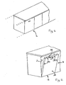
Figure 1 is a partly interrupted view, with some parts (shown by dashed lines) cut away in order to better illustrate others, of a fully integrated electrical household appliance according to this invention; -
Figure 2 shows the electrical household appliance ofFigure 1 with the door open; -
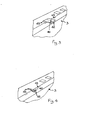
Figures 3 and 4 illustrate two alternative details of an electrical household appliance in accordance with this invention; -
Figures 5 and 6 illustrate two alternative details of an electrical household appliance in accordance with this invention. - With reference to the accompanying drawings, the
numeral 1 denotes an electrical household appliance. - More specifically, the
electrical household appliance 1 is an integrated electrical household appliance. Preferably, theelectrical household appliance 1 is of the fully integrated type. Advantageously, theelectrical household appliance 1 is a dishwasher (see embodiment illustrated). In an alternative embodiment, theelectrical household appliance 1 might be a refrigerator or an oven. - The
electrical household appliance 1 comprises: - a working
compartment 2 for product treatment; - a
door 3 giving access to thecompartment 2. Thedoor 3 is movable at least between an open position where it allows access to the workingcompartment 2 and a closed position where it prevents access to the workingcompartment 2. Thedoor 3 comprises afirst face 32 directed towards thecompartment 2 when thedoor 3 is in the closed configuration and asecond face 33 facing in the opposite direction (typically covering the front of the electrical household appliance 1). Thedoor 3 comprises at least two elements placed face to face: one of the two elements is afunctional element 36 which (when thedoor 3 is closed) sealingly closes thecompartment 2; the second element is an aesthetic covering 37. Theaesthetic covering 37 is applied to thefunctional element 36 on the side opposite the one that delimits thecompartment 2. Thesecond face 33 is integrated in the aesthetic covering 37. For example, the aesthetic covering 37 is a panel made of wood or laminate. The first and thesecond face - The
door 3 comprises aperimeter edge 30. Conveniently, theperimeter edge 30 is interposed between the first andsecond faces - The
door 3 comprises awarning light 35. The latter is advantageously located on theperimeter edge 30. For example, thewarning light 35 is a LED. Normally, when thedoor 3 is in the closed position, thewarning light 35 is not visible to a user. - The
electrical household appliance 1 also comprises a light guide 4 applied to theedge 30 of thedoor 3. The light guide 4 extends along a line ofextension 40 between aninlet 41 and anoutlet 42. Theinlet 41 directed towards a luminous signal emittable by thewarning light 35. More specifically, theinlet 41 faces thewarning light 35. Theoutlet 42 is directed towards areference plane 34 which fronts thedoor 3 in the closed position. Conveniently, thereference plane 34 is substantially parallel to thedoor 3 in the closed position. Thereference plane 34 is external to thecompartment 2. In a dishwasher the light guide 4 and thewarning light 35 form part of signalling means for indicating the progress of the washing cycle. More specifically, the light guide 4 and thewarning light 35 form part of signalling means for indicating the end of the washing cycle. The light guide 4 and thewarning light 35 might, however, also form part of signalling means for indicating other information about the washing cycle and/or, more generally, about theelectrical household appliance 1. To distinguish between different items of information, each item of information might be associated with a light signal having a predetermined colour and/or a specific luminous intensity and/or a specific flashing frequency. Conveniently, the light guide 4 is deformable. The pressure necessary to deform the light guide 4 is such that it can be applied manually. The light guide 4 is deformable at ambient temperature. More specifically, the light guide 4 is flexible. It can therefore be bent. The light guide 4 can be shaped manually. Advantageously, the above mentioned characteristics derive from the inherent properties of the material the light guide 4 is made of. - In a first embodiment, the line of
extension 40 of the light guide 4 is deformable. Preferably, at least onesection 43 of the light guide 4 is deformable, thesection 43 being at right angles to the line ofextension 40. - A preponderant stretch of the light guide 4 has a
section 43 which is at right angles to the line ofextension 40 and manually deformable. - Conveniently, any
section 43 of the light guide 4 is manually deformable, thesection 43 being at right angles to the line ofextension 40. - The deformability of the light guide 4 in general and, in particular, of the at least one section of it 43 makes it easier to position the light guide 4 even in confined spaces. In a first embodiment, the light guide 4 can be modelled, since it is sufficiently rigid to maintain the configuration adopted after being deformed. More specifically, the light guide 4 is sufficiently rigid to maintain the configuration adopted by the line of
extension 40. That makes it possible to prevent the line ofextension 40 of the light guide 4 from sagging as a result of gravity under the weight of the light guide 4 itself (for example, in the stretches where the light guide 4 is not supported by theedge 30 of the door 3). The end user can therefore reversibly modify the shape of the light guide 4. - Preferably, the light guide 4 extends uninterruptedly along the line of
extension 40 and/or at right angles to the line ofextension 40. - Advantageously, the light guide 4 is made of polymethylmethacrylate (PMMA). The light guide 4 might also be a flexible optic fibre.
- In one particular embodiment, the light guide 4, after being deformed, substantially returns to the configuration it had prior to being deformed. In this case, it has a shape memory. The light guide 4 might thus have a substantially elastic behaviour. The light guide 4 is applied to a
first side 301 of theperimeter edge 30 of thedoor 3. Conveniently, thefirst side 301 is the side of theperimeter edge 30 which is directed upwards when thedoor 3 is in the closed configuration (alternatively, thefirst side 301 might be one of the sides of theperimeter edge 30 which laterally delimit thedoor 3 or the side of theperimeter edge 30 which is directed downwards when thedoor 3 is in the closed configuration; in the latter case, the floor in front of theelectrical household appliance 1 might be conveniently used as a projection surface). Advantageously, theinlet section 41 of the light guide 4 is smaller in surface area than theoutlet section 42 of the light guide 4. That makes it possible for the controls and warning lights on theedge 30 of thedoor 3 to be concentrated while at the same time allowing a larger, and hence more easily visible, luminous outlet to be obtained. Preferably, at least one stretch of the light guide 4 along the line ofextension 40 is therefore flared. More specifically, along that stretch, thesection 43 which is at right angles to the line of extension increases with distance away from theinlet 41 and towards theoutlet 42. - There might be a plurality of warning
lights 35, each transmitting a predetermined signal. A respective light guide 4 might be associated with each of at least two warning lights 35. Alternatively, for a plurality of warning lights (for all the warning lights 35 or for a subset of them) there might be a single light guide 4 able to carry the light emitted by the plurality of warning lights. In that case, the light emitted by the warning lights is different in colour and/or intensity and/or flashing frequency so as to allow it to be distinguished by a user. - Conveniently, the
electrical household appliance 1 comprisesmeans 5 for mechanically fitting the light guide 4 to thedoor 3. The mechanical fit means 5 typically operate by interference. - In the preferred embodiment, the mechanical interference fit means 5 comprise a
housing 50 formed along theedge 30. In one particular embodiment, thehousing 50 also accommodates thewarning light 35. A portion of the light guide 4, in particular theinlet 41 of the light guide, is insertable into thehousing 50. - The mechanical interference fit means 5 perform a plurality of functions:
- they prevent infiltrations of water into the
housing 50 where thewarning light 35 is located (an electrically live zone); - they allow easy fitting;
- they allow little dispersion of the light emitted by the
warning light 35 since the inlet of the light guide 4 directly faces thewarning light 35. - Advantageously, the mechanical fit means 5 are of the unremovable type so as to prevent direct user access to the electrical section in the event of removal of the light guide 4. Alternatively, the mechanical fit means 5 might be at least partly removable to facilitate cleaning of the light guide 4 and/or of the removable components of the mechanical fit means 5 in order to remove dirt that might obstruct the passage of the light.
- Normally, there are no intermediate optical means such as mirrors, lenses, etc. interposed between the light guide 4 and the
warning light 35. This guarantees greater constructional simplicity for theelectrical household appliance 1 but without limiting the scope of the invention. The application of optical means between the light guide 4 and thewarning light 35 is in any case possible. - At least one portion of the light guide 4 can be cut with a cutting tool, in particular a hand-operated cutting tool such as a pair of steel scissors. This allows the shape of the light guide 4 to be adapted to suit the preferences of the user and to match the scheme in which the light guide 4 is installed.
- Advantageously, the light guide 4 can be cut with a cutting tool transversally to the line of
extension 40. - Advantageously, the user can cut the light guide 4 to give it a desired shape, for example to make the flared stretch of the light guide 4 along the line of
extension 40. - This invention also has for an object a system comprising:
- a fully integrated
electrical household appliance 1 having one or more of the technical features described above; - covering means 6 which, when the
door 3 is in the closed position, cover part of theedge 30 the light guide 4 is applied to. - The covering means 6 comprise a
first portion 60 which, when thedoor 3 is in the closed position, surmounts vertically (relative to the physical vertical) the portion of theedge 30 of thedoor 3 the light guide 4 is applied to. - The covering means 6 comprise a
protrusion 61 which projects from at least afirst part 62 of thefirst portion 60 of the covering means 6. Theprotrusion 61 projects towards thereference plane 34 as far as an imaginaryvertical plane 600. Thereference plane 34 is substantially parallel to the imaginaryvertical plane 600. The imaginaryvertical plane 600 is substantially parallel to a plane in which thedoor 3, when it is in the closed configuration, extends. - In a first embodiment, a
zone 63 of thefirst portion 60 of the covering means 6 (separate from the first part 62) forms part of theelectrical household appliance 1. Thezone 63 faces theelectrical household appliance 1edge 30 the light guide 4 is applied to. Advantageously, thezone 63 is integrated in the casing of the electrical household appliance 1 (seeFigure 6 ). Thefirst part 62 of thefirst portion 60 and theprotrusion 61 might, instead, form part of awork top 6 external to theelectrical household appliance 1 and not integrated in the casing of the electrical household appliance 1 (seeFigure 5 ). - In this embodiment, the covering means 6 are completely external to the
electrical household appliance 1 and are not integrated in the casing of theelectrical household appliance 1. In this case, the covering means 6 comprise awork top 64 under which theelectrical household appliance 1 can be inserted. Advantageously, thework top 64 is shared with the cabinets adjacent to theelectrical household appliance 1. - When the
door 3 is in the closed position, the light guide 4 projects from thedoor 3 at least as far as the verticalimaginary plane 600. The light guide 4 can be cut with a cutting tool (preferably a pair of steel scissors) transversally to the line ofextension 40 at the verticalimaginary plane 600. - This invention also has for an object a method for applying a light guide 4 to a system having one or more of the features outlined above. The method comprises the following steps:
- opening the
door 3 at least partially; - positioning the
inlet section 41 of the light guide 4 at thewarning light 35; - closing the
door 3. - Closing the
door 3 causes the light guide 4 to come into contact with the covering means 6 and thus to deform the light guide 4 in such a way that it fits snugly into the space between thedoor 3 and the covering means 6. More specifically, when thedoor 3 is closed, the light guide 4 can occupy the free space in the space between thedoor 3 and the covering means 6. - The method also comprises the step of cutting the light guide 4 at the imaginary
vertical plane 600. This avoids making unattractive extensions of the light guide 4 projecting beyond the edge of theprotrusion 61. At the same time, it allows a light beam to be obtained which is projected freely into the surrounding space. On the other hand, if the light guide 4 terminated behind the edge of the protrusion 61 (precisely on account of the latter) the light signal emitted would be much more difficult to see from points located at heights above theoutlet 42 of the light guide 4. This invention has important advantages. - First of all, it makes the light guide 4 very easy to adapt to the space available. This is particularly advantageous because it means the
electrical household appliance 1 is more adaptable to dimensional constraints, in particular the constraints due to the work top placed over the appliance (at a predetermined and invariable height) by a fitted kitchen installer. - Also, the shape of the light guide 4 can be modified by the end user.
- It shall be understood that the invention described above may be modified and adapted in several ways without departing from the scope of the inventive concept. Moreover, all the details of the invention may be substituted by other technically equivalent elements. In practice, all the materials used, as well as the dimensions, may vary according to requirements.
Claims (14)
- An electrical household appliance comprising:- a working compartment (2) for product treatment;- a door (3) giving access to the compartment (2), the door (3) comprising a perimeter edge (30) and a warning light (35); the door (3) being movable at least between an open position where it allows access to the working compartment (2) and a closed position where it prevents access to the working compartment (2);- a light guide (4) applied to the edge of the door and extending along a line of extension (40) between an inlet of it (41) directed towards a luminous signal emittable by the warning light (35) and an outlet of it (42) directed towards a reference plane (34) which fronts the door (3) in the closed position;characterized in that the light guide (4) is deformable.
- The electrical household appliance according to claim 1, characterized in that at least one section (43) of the light guide (4), at right angles to the line of extension (40), is deformable.
- The electrical household appliance according to claim 1 or 2, characterized in that any section (43) of the light guide (4), at right angles to the line of extension (40), is deformable.
- The electrical household appliance according to any of the foregoing claims, characterized in that the light guide (4) can be modelled, since it is sufficiently rigid to maintain the configuration adopted after being deformed.
- The electrical household appliance according to any of the foregoing claims, characterized in that the surface of the light guide (4) inlet (41) is smaller in area than the surface of the light guide (4) outlet (42).
- The electrical household appliance according to any of the foregoing claims, characterized in that it comprises means (5) for mechanically fitting the light guide (4) to the door (3) by interference.
- The electrical household appliance according to claim 6, characterized in that the mechanical interference fitting means (5) comprise a housing (50) formed along the edge (30), the light guide (4) inlet (41) being insertable in the housing (50).
- The electrical household appliance according to any of the foregoing claims, characterized in that at least one portion of the light guide (4) can be cut out with a cutting tool.
- The electrical household appliance according to any of the foregoing claims, characterized in that it is a fully integrated dishwasher, the warning light (35) and the light guide (4) forming part of means for indicating the progress of the washing cycle.
- A system characterized in that it comprises:- a fully integrated electrical household appliance (1) according to any of the claims from 1 to 9;- covering means (6) which, when the door (3) is in the closed position, cover part of the edge (30) the light guide (4) is applied to.
- The system according to claim 10, characterized in that:- the covering means (6) comprise a first portion (60) which, when the door (3) is in the closed position, vertically surmounts the door (3) edge (30) the light guide (4) is applied to;- the covering means (6) comprise a protrusion (61) which projects from at least a first part (62) of the first portion (60) of the covering means (6), the protrusion (61) projecting towards the reference plane (34) as far as an imaginary vertical plane (600);- when the door (3) is in the closed position, the light guide (4) projects from the edge (30) of the door (3) at least as far as the vertical imaginary plane (600), it being possible to cut the light guide (4) with a cutting tool transversally of the line of extension (40) at the vertical imaginary plane (600).
- The system according to claim 10 or 11, characterized in that a zone (63) of the first portion (60) of the covering means (6) forms part of the electrical household appliance (1) and faces the electrical household appliance (1) edge (30) the light guide (4) is applied to.
- A method for applying a light guide to a system according to claim 10, 11 or 12, comprising the following steps:- opening the door (3) at least partially;- positioning the inlet (41) of the light guide (4) at the warning light (4);- closing the door (3), this step causing the light guide (4) to come into contact with the covering means (6) and thus to deform the light guide (4) in such a way that it fits snugly into the space between the door (3) and the covering means (6).
- The method for applying a light guide to a system having at least the characteristics of claim 11 or of claim 12 when it depends on claim 11, comprising the following steps:- opening the door (3) at least partially;- positioning the inlet (41) of the light guide (4) at the warning light (35);- closing the door (3), this step causing the light guide (4) to come into contact with the covering means (6) and thus to deform the light guide (4) in such a way that it fits snugly into the space between the door (3) and the covering means (6);- cutting the light guide (4) at the imaginary vertical plane (600).
Priority Applications (1)
| Application Number | Priority Date | Filing Date | Title |
|---|---|---|---|
| PL11001609T PL2363056T3 (en) | 2010-03-02 | 2011-02-28 | Electrical household appliance |
Applications Claiming Priority (1)
| Application Number | Priority Date | Filing Date | Title |
|---|---|---|---|
| IT000005A ITRN20100005A1 (en) | 2010-03-02 | 2010-03-02 | APPLIANCE |
Publications (2)
| Publication Number | Publication Date |
|---|---|
| EP2363056A1 true EP2363056A1 (en) | 2011-09-07 |
| EP2363056B1 EP2363056B1 (en) | 2012-11-07 |
Family
ID=42782047
Family Applications (1)
| Application Number | Title | Priority Date | Filing Date |
|---|---|---|---|
| EP11001609A Not-in-force EP2363056B1 (en) | 2010-03-02 | 2011-02-28 | Electrical household appliance |
Country Status (3)
| Country | Link |
|---|---|
| EP (1) | EP2363056B1 (en) |
| IT (1) | ITRN20100005A1 (en) |
| PL (1) | PL2363056T3 (en) |
Cited By (7)
| Publication number | Priority date | Publication date | Assignee | Title |
|---|---|---|---|---|
| EP2420176A3 (en) * | 2010-08-17 | 2014-03-05 | Vestel Beyaz Esya Sanayi Ve Ticaret A.S. | A dishwasher |
| WO2015039774A1 (en) * | 2013-09-18 | 2015-03-26 | BSH Bosch und Siemens Hausgeräte GmbH | Display unit for a household appliance |
| JP2015167771A (en) * | 2014-03-10 | 2015-09-28 | パナソニックIpマネジメント株式会社 | dishwasher |
| WO2016103095A1 (en) * | 2014-12-26 | 2016-06-30 | BSH Hausgeräte GmbH | Household appliance having light source |
| WO2016103084A1 (en) * | 2014-12-26 | 2016-06-30 | BSH Hausgeräte GmbH | Household appliance |
| WO2016103096A1 (en) * | 2014-12-26 | 2016-06-30 | BSH Hausgeräte GmbH | Household appliance having light guide apparatus |
| WO2016103083A1 (en) * | 2014-12-26 | 2016-06-30 | BSH Hausgeräte GmbH | Household appliance having light-emitting component |
Families Citing this family (1)
| Publication number | Priority date | Publication date | Assignee | Title |
|---|---|---|---|---|
| US11278179B2 (en) | 2019-04-23 | 2022-03-22 | Haier Us Appliance Solutions, Inc. | Status indicator and lighting assembly for an appliance door |
Citations (7)
| Publication number | Priority date | Publication date | Assignee | Title |
|---|---|---|---|---|
| EP0101048A2 (en) * | 1982-08-13 | 1984-02-22 | Nippon Telegraph And Telephone Corporation | Plastic optical fibers |
| DE29914825U1 (en) * | 1999-08-26 | 2000-06-08 | L + H Kabeltechnik GmbH, 75242 Neuhausen | Apparatus for performing a cable end surface finishing process |
| EP1151717A2 (en) * | 2000-05-06 | 2001-11-07 | Miele & Cie. GmbH & Co. | Dishwasher, in particular built in dishwasher with an optical operating status display |
| WO2004056256A1 (en) * | 2002-12-19 | 2004-07-08 | BSH Bosch und Siemens Hausgeräte GmbH | Domestic appliance, in particular a built-in domestic appliance |
| WO2006092598A2 (en) * | 2005-03-02 | 2006-09-08 | Javed Khanzada | Source of decorative illumination and personal adornment |
| EP1702551A1 (en) * | 2006-03-31 | 2006-09-20 | V-Zug AG | Domestic appliance with decorative panel and optical display integrated therein |
| US20080008430A1 (en) * | 2006-07-06 | 2008-01-10 | Anthony Stephen Kewitsch | Shape-Retaining Fiber Optic Cables Having Limited Bend Radius |
-
2010
- 2010-03-02 IT IT000005A patent/ITRN20100005A1/en unknown
-
2011
- 2011-02-28 EP EP11001609A patent/EP2363056B1/en not_active Not-in-force
- 2011-02-28 PL PL11001609T patent/PL2363056T3/en unknown
Patent Citations (7)
| Publication number | Priority date | Publication date | Assignee | Title |
|---|---|---|---|---|
| EP0101048A2 (en) * | 1982-08-13 | 1984-02-22 | Nippon Telegraph And Telephone Corporation | Plastic optical fibers |
| DE29914825U1 (en) * | 1999-08-26 | 2000-06-08 | L + H Kabeltechnik GmbH, 75242 Neuhausen | Apparatus for performing a cable end surface finishing process |
| EP1151717A2 (en) * | 2000-05-06 | 2001-11-07 | Miele & Cie. GmbH & Co. | Dishwasher, in particular built in dishwasher with an optical operating status display |
| WO2004056256A1 (en) * | 2002-12-19 | 2004-07-08 | BSH Bosch und Siemens Hausgeräte GmbH | Domestic appliance, in particular a built-in domestic appliance |
| WO2006092598A2 (en) * | 2005-03-02 | 2006-09-08 | Javed Khanzada | Source of decorative illumination and personal adornment |
| EP1702551A1 (en) * | 2006-03-31 | 2006-09-20 | V-Zug AG | Domestic appliance with decorative panel and optical display integrated therein |
| US20080008430A1 (en) * | 2006-07-06 | 2008-01-10 | Anthony Stephen Kewitsch | Shape-Retaining Fiber Optic Cables Having Limited Bend Radius |
Cited By (10)
| Publication number | Priority date | Publication date | Assignee | Title |
|---|---|---|---|---|
| EP2420176A3 (en) * | 2010-08-17 | 2014-03-05 | Vestel Beyaz Esya Sanayi Ve Ticaret A.S. | A dishwasher |
| WO2015039774A1 (en) * | 2013-09-18 | 2015-03-26 | BSH Bosch und Siemens Hausgeräte GmbH | Display unit for a household appliance |
| JP2015167771A (en) * | 2014-03-10 | 2015-09-28 | パナソニックIpマネジメント株式会社 | dishwasher |
| WO2016103095A1 (en) * | 2014-12-26 | 2016-06-30 | BSH Hausgeräte GmbH | Household appliance having light source |
| WO2016103084A1 (en) * | 2014-12-26 | 2016-06-30 | BSH Hausgeräte GmbH | Household appliance |
| WO2016103096A1 (en) * | 2014-12-26 | 2016-06-30 | BSH Hausgeräte GmbH | Household appliance having light guide apparatus |
| WO2016103083A1 (en) * | 2014-12-26 | 2016-06-30 | BSH Hausgeräte GmbH | Household appliance having light-emitting component |
| CN105780390A (en) * | 2014-12-26 | 2016-07-20 | 博西华电器(江苏)有限公司 | Household appliance with light guide device |
| RU2685880C2 (en) * | 2014-12-26 | 2019-04-23 | Бсх Хаусгерете Гмбх | Household appliance, having light source |
| CN105780390B (en) * | 2014-12-26 | 2019-10-29 | 博西华电器(江苏)有限公司 | Household electrical appliance with guiding device |
Also Published As
| Publication number | Publication date |
|---|---|
| PL2363056T3 (en) | 2013-04-30 |
| EP2363056B1 (en) | 2012-11-07 |
| ITRN20100005A1 (en) | 2011-09-03 |
Similar Documents
| Publication | Publication Date | Title |
|---|---|---|
| EP2363056B1 (en) | Electrical household appliance | |
| KR102094838B1 (en) | Home appliance with display unit | |
| ES2363166T3 (en) | APPLIANCE APPLIANCE, IN PARTICULAR APPLIANCE APPLIANCE EQUIPMENT WITH A CONTROLLABLE OPERATING INDICATION. | |
| EP2355686B1 (en) | Console assembly for a dishwashing appliance, and associated apparatus | |
| EP2778585A2 (en) | Methods and apparatus to provide lighting in refrigerators | |
| US20160186984A1 (en) | Appliance having a human-machine interface and illuminated handle recess | |
| KR102178897B1 (en) | Lighting device for fitting into a wall surface of a domestic electrical appliance | |
| ITTO940555A1 (en) | HOUSEHOLD APPLIANCE APPARATUS OF THE INTEGRABLE TYPE | |
| JP6403244B2 (en) | Kitchen equipment | |
| EP3237670B1 (en) | Household appliance having light source | |
| WO2018001509A1 (en) | Warming drawer with an improved sealing perfomance | |
| WO2016103096A1 (en) | Household appliance having light guide apparatus | |
| EP3367870B1 (en) | A household appliance with an operation indicator | |
| JP5985233B2 (en) | Kitchen equipment and kitchen cabinet in which the kitchen equipment is incorporated | |
| EP3237669B1 (en) | Household appliance | |
| EP3089644B1 (en) | Dishwasher | |
| ATE453007T1 (en) | HOUSEHOLD APPLIANCE, IN PARTICULAR LAUNDRY TREATMENT MACHINE SUCH AS WASHING MACHINE, WASHER-DRYER OR CLOTHES-DRYER, HAVING A CONTROL PANEL. | |
| JP2017161178A (en) | Indoor machine of air conditioner | |
| JP2015167771A (en) | dishwasher | |
| EP2307808B1 (en) | Kitchen oven | |
| JP6621007B2 (en) | Cooktop | |
| EP2977500B1 (en) | Washing machine or dryer with a front bottom panel | |
| WO2016103084A1 (en) | Household appliance | |
| KR101233195B1 (en) | Control panel of washing machine | |
| EP2591711A1 (en) | Virtual buttons |
Legal Events
| Date | Code | Title | Description |
|---|---|---|---|
| PUAI | Public reference made under article 153(3) epc to a published international application that has entered the european phase |
Free format text: ORIGINAL CODE: 0009012 |
|
| AK | Designated contracting states |
Kind code of ref document: A1 Designated state(s): AL AT BE BG CH CY CZ DE DK EE ES FI FR GB GR HR HU IE IS IT LI LT LU LV MC MK MT NL NO PL PT RO RS SE SI SK SM TR |
|
| AX | Request for extension of the european patent |
Extension state: BA ME |
|
| 17P | Request for examination filed |
Effective date: 20120307 |
|
| GRAP | Despatch of communication of intention to grant a patent |
Free format text: ORIGINAL CODE: EPIDOSNIGR1 |
|
| RIC1 | Information provided on ipc code assigned before grant |
Ipc: A47L 15/42 20060101AFI20120508BHEP |
|
| GRAS | Grant fee paid |
Free format text: ORIGINAL CODE: EPIDOSNIGR3 |
|
| GRAA | (expected) grant |
Free format text: ORIGINAL CODE: 0009210 |
|
| AK | Designated contracting states |
Kind code of ref document: B1 Designated state(s): AL AT BE BG CH CY CZ DE DK EE ES FI FR GB GR HR HU IE IS IT LI LT LU LV MC MK MT NL NO PL PT RO RS SE SI SK SM TR |
|
| REG | Reference to a national code |
Ref country code: GB Ref legal event code: FG4D |
|
| REG | Reference to a national code |
Ref country code: AT Ref legal event code: REF Ref document number: 582647 Country of ref document: AT Kind code of ref document: T Effective date: 20121115 Ref country code: CH Ref legal event code: EP |
|
| REG | Reference to a national code |
Ref country code: IE Ref legal event code: FG4D |
|
| REG | Reference to a national code |
Ref country code: DE Ref legal event code: R096 Ref document number: 602011000389 Country of ref document: DE Effective date: 20130103 |
|
| REG | Reference to a national code |
Ref country code: AT Ref legal event code: MK05 Ref document number: 582647 Country of ref document: AT Kind code of ref document: T Effective date: 20121107 |
|
| REG | Reference to a national code |
Ref country code: NL Ref legal event code: VDEP Effective date: 20121107 |
|
| REG | Reference to a national code |
Ref country code: LT Ref legal event code: MG4D |
|
| PG25 | Lapsed in a contracting state [announced via postgrant information from national office to epo] |
Ref country code: HR Free format text: LAPSE BECAUSE OF FAILURE TO SUBMIT A TRANSLATION OF THE DESCRIPTION OR TO PAY THE FEE WITHIN THE PRESCRIBED TIME-LIMIT Effective date: 20121107 Ref country code: IS Free format text: LAPSE BECAUSE OF FAILURE TO SUBMIT A TRANSLATION OF THE DESCRIPTION OR TO PAY THE FEE WITHIN THE PRESCRIBED TIME-LIMIT Effective date: 20130307 Ref country code: LT Free format text: LAPSE BECAUSE OF FAILURE TO SUBMIT A TRANSLATION OF THE DESCRIPTION OR TO PAY THE FEE WITHIN THE PRESCRIBED TIME-LIMIT Effective date: 20121107 Ref country code: NL Free format text: LAPSE BECAUSE OF FAILURE TO SUBMIT A TRANSLATION OF THE DESCRIPTION OR TO PAY THE FEE WITHIN THE PRESCRIBED TIME-LIMIT Effective date: 20121107 Ref country code: FI Free format text: LAPSE BECAUSE OF FAILURE TO SUBMIT A TRANSLATION OF THE DESCRIPTION OR TO PAY THE FEE WITHIN THE PRESCRIBED TIME-LIMIT Effective date: 20121107 Ref country code: NO Free format text: LAPSE BECAUSE OF FAILURE TO SUBMIT A TRANSLATION OF THE DESCRIPTION OR TO PAY THE FEE WITHIN THE PRESCRIBED TIME-LIMIT Effective date: 20130207 Ref country code: SE Free format text: LAPSE BECAUSE OF FAILURE TO SUBMIT A TRANSLATION OF THE DESCRIPTION OR TO PAY THE FEE WITHIN THE PRESCRIBED TIME-LIMIT Effective date: 20121107 |
|
| REG | Reference to a national code |
Ref country code: PL Ref legal event code: T3 |
|
| PG25 | Lapsed in a contracting state [announced via postgrant information from national office to epo] |
Ref country code: SI Free format text: LAPSE BECAUSE OF FAILURE TO SUBMIT A TRANSLATION OF THE DESCRIPTION OR TO PAY THE FEE WITHIN THE PRESCRIBED TIME-LIMIT Effective date: 20121107 Ref country code: GR Free format text: LAPSE BECAUSE OF FAILURE TO SUBMIT A TRANSLATION OF THE DESCRIPTION OR TO PAY THE FEE WITHIN THE PRESCRIBED TIME-LIMIT Effective date: 20130208 Ref country code: PT Free format text: LAPSE BECAUSE OF FAILURE TO SUBMIT A TRANSLATION OF THE DESCRIPTION OR TO PAY THE FEE WITHIN THE PRESCRIBED TIME-LIMIT Effective date: 20130307 Ref country code: BE Free format text: LAPSE BECAUSE OF FAILURE TO SUBMIT A TRANSLATION OF THE DESCRIPTION OR TO PAY THE FEE WITHIN THE PRESCRIBED TIME-LIMIT Effective date: 20121107 Ref country code: LV Free format text: LAPSE BECAUSE OF FAILURE TO SUBMIT A TRANSLATION OF THE DESCRIPTION OR TO PAY THE FEE WITHIN THE PRESCRIBED TIME-LIMIT Effective date: 20121107 |
|
| PG25 | Lapsed in a contracting state [announced via postgrant information from national office to epo] |
Ref country code: AT Free format text: LAPSE BECAUSE OF FAILURE TO SUBMIT A TRANSLATION OF THE DESCRIPTION OR TO PAY THE FEE WITHIN THE PRESCRIBED TIME-LIMIT Effective date: 20121107 |
|
| PG25 | Lapsed in a contracting state [announced via postgrant information from national office to epo] |
Ref country code: SK Free format text: LAPSE BECAUSE OF FAILURE TO SUBMIT A TRANSLATION OF THE DESCRIPTION OR TO PAY THE FEE WITHIN THE PRESCRIBED TIME-LIMIT Effective date: 20121107 Ref country code: RS Free format text: LAPSE BECAUSE OF FAILURE TO SUBMIT A TRANSLATION OF THE DESCRIPTION OR TO PAY THE FEE WITHIN THE PRESCRIBED TIME-LIMIT Effective date: 20121107 Ref country code: BG Free format text: LAPSE BECAUSE OF FAILURE TO SUBMIT A TRANSLATION OF THE DESCRIPTION OR TO PAY THE FEE WITHIN THE PRESCRIBED TIME-LIMIT Effective date: 20130207 Ref country code: CZ Free format text: LAPSE BECAUSE OF FAILURE TO SUBMIT A TRANSLATION OF THE DESCRIPTION OR TO PAY THE FEE WITHIN THE PRESCRIBED TIME-LIMIT Effective date: 20121107 Ref country code: EE Free format text: LAPSE BECAUSE OF FAILURE TO SUBMIT A TRANSLATION OF THE DESCRIPTION OR TO PAY THE FEE WITHIN THE PRESCRIBED TIME-LIMIT Effective date: 20121107 Ref country code: DK Free format text: LAPSE BECAUSE OF FAILURE TO SUBMIT A TRANSLATION OF THE DESCRIPTION OR TO PAY THE FEE WITHIN THE PRESCRIBED TIME-LIMIT Effective date: 20121107 |
|
| PG25 | Lapsed in a contracting state [announced via postgrant information from national office to epo] |
Ref country code: RO Free format text: LAPSE BECAUSE OF FAILURE TO SUBMIT A TRANSLATION OF THE DESCRIPTION OR TO PAY THE FEE WITHIN THE PRESCRIBED TIME-LIMIT Effective date: 20121107 |
|
| PLBE | No opposition filed within time limit |
Free format text: ORIGINAL CODE: 0009261 |
|
| STAA | Information on the status of an ep patent application or granted ep patent |
Free format text: STATUS: NO OPPOSITION FILED WITHIN TIME LIMIT |
|
| PG25 | Lapsed in a contracting state [announced via postgrant information from national office to epo] |
Ref country code: MC Free format text: LAPSE BECAUSE OF NON-PAYMENT OF DUE FEES Effective date: 20130228 |
|
| 26N | No opposition filed |
Effective date: 20130808 |
|
| PG25 | Lapsed in a contracting state [announced via postgrant information from national office to epo] |
Ref country code: ES Free format text: LAPSE BECAUSE OF FAILURE TO SUBMIT A TRANSLATION OF THE DESCRIPTION OR TO PAY THE FEE WITHIN THE PRESCRIBED TIME-LIMIT Effective date: 20130218 |
|
| PG25 | Lapsed in a contracting state [announced via postgrant information from national office to epo] |
Ref country code: CY Free format text: LAPSE BECAUSE OF FAILURE TO SUBMIT A TRANSLATION OF THE DESCRIPTION OR TO PAY THE FEE WITHIN THE PRESCRIBED TIME-LIMIT Effective date: 20121107 |
|
| REG | Reference to a national code |
Ref country code: IE Ref legal event code: MM4A |
|
| REG | Reference to a national code |
Ref country code: DE Ref legal event code: R097 Ref document number: 602011000389 Country of ref document: DE Effective date: 20130808 |
|
| PG25 | Lapsed in a contracting state [announced via postgrant information from national office to epo] |
Ref country code: AL Free format text: LAPSE BECAUSE OF FAILURE TO SUBMIT A TRANSLATION OF THE DESCRIPTION OR TO PAY THE FEE WITHIN THE PRESCRIBED TIME-LIMIT Effective date: 20121107 Ref country code: IE Free format text: LAPSE BECAUSE OF NON-PAYMENT OF DUE FEES Effective date: 20130228 |
|
| PG25 | Lapsed in a contracting state [announced via postgrant information from national office to epo] |
Ref country code: MT Free format text: LAPSE BECAUSE OF FAILURE TO SUBMIT A TRANSLATION OF THE DESCRIPTION OR TO PAY THE FEE WITHIN THE PRESCRIBED TIME-LIMIT Effective date: 20121107 |
|
| REG | Reference to a national code |
Ref country code: CH Ref legal event code: PL |
|
| PG25 | Lapsed in a contracting state [announced via postgrant information from national office to epo] |
Ref country code: CH Free format text: LAPSE BECAUSE OF NON-PAYMENT OF DUE FEES Effective date: 20140228 Ref country code: LI Free format text: LAPSE BECAUSE OF NON-PAYMENT OF DUE FEES Effective date: 20140228 |
|
| REG | Reference to a national code |
Ref country code: FR Ref legal event code: PLFP Year of fee payment: 5 |
|
| PG25 | Lapsed in a contracting state [announced via postgrant information from national office to epo] |
Ref country code: SM Free format text: LAPSE BECAUSE OF FAILURE TO SUBMIT A TRANSLATION OF THE DESCRIPTION OR TO PAY THE FEE WITHIN THE PRESCRIBED TIME-LIMIT Effective date: 20121107 |
|
| PG25 | Lapsed in a contracting state [announced via postgrant information from national office to epo] |
Ref country code: TR Free format text: LAPSE BECAUSE OF FAILURE TO SUBMIT A TRANSLATION OF THE DESCRIPTION OR TO PAY THE FEE WITHIN THE PRESCRIBED TIME-LIMIT Effective date: 20121107 |
|
| PG25 | Lapsed in a contracting state [announced via postgrant information from national office to epo] |
Ref country code: LU Free format text: LAPSE BECAUSE OF NON-PAYMENT OF DUE FEES Effective date: 20130228 Ref country code: HU Free format text: LAPSE BECAUSE OF FAILURE TO SUBMIT A TRANSLATION OF THE DESCRIPTION OR TO PAY THE FEE WITHIN THE PRESCRIBED TIME-LIMIT; INVALID AB INITIO Effective date: 20110228 Ref country code: MK Free format text: LAPSE BECAUSE OF FAILURE TO SUBMIT A TRANSLATION OF THE DESCRIPTION OR TO PAY THE FEE WITHIN THE PRESCRIBED TIME-LIMIT Effective date: 20121107 |
|
| REG | Reference to a national code |
Ref country code: FR Ref legal event code: PLFP Year of fee payment: 6 |
|
| REG | Reference to a national code |
Ref country code: FR Ref legal event code: PLFP Year of fee payment: 7 |
|
| REG | Reference to a national code |
Ref country code: FR Ref legal event code: PLFP Year of fee payment: 8 |
|
| PGFP | Annual fee paid to national office [announced via postgrant information from national office to epo] |
Ref country code: PL Payment date: 20171213 Year of fee payment: 8 |
|
| PG25 | Lapsed in a contracting state [announced via postgrant information from national office to epo] |
Ref country code: PL Free format text: LAPSE BECAUSE OF NON-PAYMENT OF DUE FEES Effective date: 20190228 |
|
| PGFP | Annual fee paid to national office [announced via postgrant information from national office to epo] |
Ref country code: FR Payment date: 20210113 Year of fee payment: 11 Ref country code: IT Payment date: 20210112 Year of fee payment: 11 |
|
| PGFP | Annual fee paid to national office [announced via postgrant information from national office to epo] |
Ref country code: DE Payment date: 20210216 Year of fee payment: 11 Ref country code: GB Payment date: 20210217 Year of fee payment: 11 |
|
| REG | Reference to a national code |
Ref country code: DE Ref legal event code: R119 Ref document number: 602011000389 Country of ref document: DE |
|
| GBPC | Gb: european patent ceased through non-payment of renewal fee |
Effective date: 20220228 |
|
| PG25 | Lapsed in a contracting state [announced via postgrant information from national office to epo] |
Ref country code: FR Free format text: LAPSE BECAUSE OF NON-PAYMENT OF DUE FEES Effective date: 20220228 |
|
| PG25 | Lapsed in a contracting state [announced via postgrant information from national office to epo] |
Ref country code: GB Free format text: LAPSE BECAUSE OF NON-PAYMENT OF DUE FEES Effective date: 20220228 Ref country code: DE Free format text: LAPSE BECAUSE OF NON-PAYMENT OF DUE FEES Effective date: 20220901 |
|
| PG25 | Lapsed in a contracting state [announced via postgrant information from national office to epo] |
Ref country code: IT Free format text: LAPSE BECAUSE OF NON-PAYMENT OF DUE FEES Effective date: 20220228 |