EP2363034A1 - Connecting device of strap and appurtenance - Google Patents
Connecting device of strap and appurtenance Download PDFInfo
- Publication number
- EP2363034A1 EP2363034A1 EP10157213A EP10157213A EP2363034A1 EP 2363034 A1 EP2363034 A1 EP 2363034A1 EP 10157213 A EP10157213 A EP 10157213A EP 10157213 A EP10157213 A EP 10157213A EP 2363034 A1 EP2363034 A1 EP 2363034A1
- Authority
- EP
- European Patent Office
- Prior art keywords
- rail
- connecting device
- strap
- free end
- plug member
- Prior art date
- Legal status (The legal status is an assumption and is not a legal conclusion. Google has not performed a legal analysis and makes no representation as to the accuracy of the status listed.)
- Withdrawn
Links
Images


Classifications
-
- A—HUMAN NECESSITIES
- A45—HAND OR TRAVELLING ARTICLES
- A45F—TRAVELLING OR CAMP EQUIPMENT: SACKS OR PACKS CARRIED ON THE BODY
- A45F3/00—Travelling or camp articles; Sacks or packs carried on the body
- A45F3/04—Sacks or packs carried on the body by means of two straps passing over the two shoulders
-
- A—HUMAN NECESSITIES
- A44—HABERDASHERY; JEWELLERY
- A44B—BUTTONS, PINS, BUCKLES, SLIDE FASTENERS, OR THE LIKE
- A44B11/00—Buckles; Similar fasteners for interconnecting straps or the like, e.g. for safety belts
- A44B11/006—Attachment of buckle to strap
- A44B11/008—Attachment of buckle to strap extensible
-
- A—HUMAN NECESSITIES
- A44—HABERDASHERY; JEWELLERY
- A44B—BUTTONS, PINS, BUCKLES, SLIDE FASTENERS, OR THE LIKE
- A44B11/00—Buckles; Similar fasteners for interconnecting straps or the like, e.g. for safety belts
- A44B11/25—Buckles; Similar fasteners for interconnecting straps or the like, e.g. for safety belts with two or more separable parts
- A44B11/2592—Buckles; Similar fasteners for interconnecting straps or the like, e.g. for safety belts with two or more separable parts fastening by sliding in the main plane or a plane parallel to the main plane of the buckle
- A44B11/2596—Buckles; Similar fasteners for interconnecting straps or the like, e.g. for safety belts with two or more separable parts fastening by sliding in the main plane or a plane parallel to the main plane of the buckle the movement being transverse to the longitudinal direction of the strap or chain
-
- A—HUMAN NECESSITIES
- A45—HAND OR TRAVELLING ARTICLES
- A45C—PURSES; LUGGAGE; HAND CARRIED BAGS
- A45C13/00—Details; Accessories
- A45C13/10—Arrangement of fasteners
- A45C13/1076—Arrangement of fasteners with a snap action
-
- A—HUMAN NECESSITIES
- A45—HAND OR TRAVELLING ARTICLES
- A45F—TRAVELLING OR CAMP EQUIPMENT: SACKS OR PACKS CARRIED ON THE BODY
- A45F3/00—Travelling or camp articles; Sacks or packs carried on the body
- A45F3/04—Sacks or packs carried on the body by means of two straps passing over the two shoulders
- A45F3/047—Sacks or packs carried on the body by means of two straps passing over the two shoulders with adjustable fastenings for the shoulder straps or waist belts
Definitions
- the present invention relates to a device for connecting a strap and an associated appurtenance to each other, which enables convenient connection or separation of straps or various associated appurtenances provided at backpacks, bags, garments, helmets, and the like.
- a backpack is provided at several positions with a great number of straps in such a manner that one end of each strap is fixed to the backpack by sewing, and various shapes of appurtenances, such as adjustors and hooks, are connected to the straps so as to be used per different functions thereof.
- the backpack is further provided with, e.g., fastening belts and belt buckles.
- a greater number of appurtenances such as a lantern, cup, alpenstock, and canteen, may be suspended from and carried by the backpack.
- Such straps or appurtenances attached to backpacks or bags provide only limited functions at fixed positions thereof and have no compatibility with other appurtenances having different functions.
- connection between a general strap and several associated appurtenances has been realized, for example, in such a manner that the strap is inserted into and wound around one or more slots perforated in each appurtenance in various ways and in turn, male and female buckles, which are adapted for individual cases, are used to connect the appurtenances to each other.
- male and female buckles which are adapted for individual cases, are used to connect the appurtenances to each other.
- the present invention has been made in view of the above problems, and it is an object of the present invention to provide a device for connecting a strap and an appurtenance to each other, which enables convenient attachment/detachment of straps or various associated appurtenances provided at backpacks, etc., thus enabling selective use thereof as occasion demands while maintaining a stable operational status of each appurtenance without abrasion despite repeated connection/separation operations.
- a connecting device of a strap and an appurtenance including a plug member including an elongated rail formed at one end thereof with a stopper and a rail support connected to a side surface of the rail, and a socket member including a rail groove configured to receive the rail, a socket longitudinally formed from an entrance of the rail groove, and a retaining hole formed in one end thereof to receive the stopper when the rail is fitted into the rail groove, wherein the end of the rail is spaced apart from the rail support to define an elastic free end, and the stopper is located in a range of the free end.
- the stopper it is possible to allow the stopper to be stably caught by the retaining hole in the course of fitting the rail into the rail groove. Also, the rail is able to be separated from the rail groove in a state wherein the stopper is released from the retaining hole as the free end is elastically pushed. This assures smooth separation of the rail without friction between the stopper and the rail groove.
- the free end of the rail may protrude outward beyond the rail support.
- This provides the free end of the rail with elasticity, enabling elastic displacement of the stopper included in the free end.
- the rail and the rail support may have the same length and a separation space may be defined between the free end of the rail and the rail support. This provides the free end of the rail with elasticity, enabling elastic displacement of the stopper included in the free end.
- the free end of the rail may be thinner than a remaining region of the rail to enhance elasticity thereof.
- a grip may be formed at a distal position of the free end and may take the form of an expanded portion.
- the stopper included in the free end may have an inclined surface facing a fixed end of the rail and a vertical surface facing the free end of the rail.
- the inclined surface of the stopper assures smooth coupling of the rail and the rail groove and the vertical surface of the stopper maintains a firmly coupled state of the rail and the rail groove.
- Fig. 2 is an exploded perspective view of a connecting device according to an embodiment of the present invention
- Fig. 3 is a plan view of a plug member illustrated in Fig. 2
- Fig. 4 is a front view of the plug member illustrated in Fig. 3
- the connecting device according to the present invention includes a plug member 100 serving as a male member and a socket member 200 serving as a female member.
- the plug member 100 and the socket member 200 are provided at respective ends of a first object A and a second object B, so as to be connected to or separated from each other.
- first object A and the second object B are illustrated as being thin fixing plates according to an exemplary configuration of the present embodiment.
- the fixing plates are made of synthetic resins and are adapted to be attached to, e.g., garments, belts, backpacks, bags, and various straps by sewing.
- the plug member 100 includes a rail support 101 and a rail 102.
- the rail support 101 is integrally formed with the first object A.
- the rail 102 protrudes from an outer edge of the rail support 101 to define a movement path having a predetermined width.
- a stopper 103 protrudes from one end of the rail 102.
- the stopper 103 has a vertical surface 104 facing a free end of the rail 102 and an inclined surface 105 facing an opposite fixed end of the rail 102.
- the movement path of the rail 102 is preferably a straight path, but may be a curved path.
- the socket member 200 to be coupled with the plug member 100 is integrally formed at one end of the second object B.
- the socket member 200 has an elongated rail groove 202 into which the rail 102 of the plug member 100 can be fitted.
- the rail groove 202 is defined in one end thereof with a C-shaped entrance 204, through which one end of the rail 102 begins to be fitted.
- the socket member 200 also has an elongated slot 205 having the same length as the rail groove 202 starting from an open end of the C-shaped entrance 204.
- the entrance 204 of the rail groove 202 preferably has the same contour as a lateral contour of the rail 102.
- the slot 205 has a smaller width than that of the rail groove 202 and functions as a passage for movement of the rail support 101.
- the slot 205 may be selectively formed in a side surface, upper surface or lower surface of the rail groove 202, the slot 205 preferably has a shape corresponding to a connecting structure of the rail 102 and the rail support 101.
- a retaining hole 203 corresponding to the stopper 103 of the rail 102 is provided near one end of the rail groove 202.
- the stopper 103 is inserted into the retaining hole 203 to maintain a coupled state of the rail 102 and the rail groove 202.
- the other end of the rail groove 202 opposite to the entrance 204 may be closed to define a closure wall 206.
- the closure wall 206 sets a movement limit when the rail 102 is pushed in a given direction so as to be fitted into the rail groove 202 and also, functions to stably limit a coupling position of the rail 102.
- One end of the rail 102 of the plug member 100 is spaced apart from the rail support 101 and defines a free end 106 having elasticity.
- the stopper 103 is located in a range of the free end 106.
- a separation space 107 is defined between the rail support 101 and one end of the rail 102 and a remaining region of the rail 102 except for the end of the rail 102 comes into contact with the rail support 101.
- the end of the rail 102 is separated from the rail support 101 so as to define the free end 106 and the remaining region of the rail 102 is connected to the rail support 101 so as to define the fixed end of the rail 102.
- the free end 106 has elasticity.
- the elastic free end 106 of the rail 102 may act to minimize frictional resistance caused when the stopper 103 comes into contact with an inner periphery of the retaining hole 203 in the course of fitting the rail 102 into the rail groove 202.
- Figs. 5 and 6 illustrate an alternative configuration of the free end of the rail.
- one end of the rail 102 of the plug member 100 protrudes outward beyond the rail support 101 to define the free end 106.
- the stopper 103 is located in a range of the free end 106.
- the free end 106 of the rail 102 is thinner than the remaining region of the rail 102.
- the free end is defined at an opposite side of a leading end of the rail that begins to be fitted into the rail groove of the socket member.
- Figs. 8 to 10 are views illustrating an alternative embodiment of the present invention in which a grip is provided at the free end of the rail.
- a grip 108 is attached to the free end 106 of the rail 102 of the plug member 100 and takes the form of an expanded plate.
- the expanded plate-shaped grip 108 has concave upper and lower surfaces to assure a stable grip operation.
- Fig. 11 illustrates an alternative configuration of the grip provided at the free end of the rail.
- the grip 108 may take the form of an expanded portion extending from the free end 106 of the rail 102 and the upper surface of the grip 108 may be inclined such that an outer end thereof protrudes upward.
- the above described configurations of the grip 108 have the effect of allowing the grip 108 provided at the free end 106 of the rail 102 to stably come into contact with and be caught by a user's finger tip when a user operates the free end 106 with his/her finger.
- the user is able to easily pull the socket member 200 out by pushing and pulling the grip 108 with his/her finger.
- two or more retaining holes 203 may be provided in the rail groove 202 of the socket member 200 to enable selective insertion of the stopper 103 and consequently, to allow the plug member 100 to be fixed at an arbitrary position.
- Each of the retaining holes 203 has an open end to be connected to the slot 205.
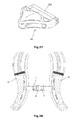
- Figs. 12 to 14 illustrate an operation of the above described connecting device according to the present invention.
- the rail 102 of the plug member 100 is longitudinally fitted into the rail groove 202 of the socket member 200.
- the rail 102 is fitted into the rail groove 202 via smooth sliding motion thereof.
- the stopper 103 is moved while coming into contact with an inner surface of the rail groove 202 and is smoothly inserted into and elastically caught by the retaining hole 203 without friction owing to elastic bending of the free end 106 of the rail 102.
- the inclined surface 105 of the stopper 103 facing the fixed end of the rail 102 realizes smooth insertion of the stopper 103.
- the vertical surface 104 of the stopper 103 facing the opposite free end 106 of the rail 102 is caught by the retaining hole 203, the vertical surface 104 makes it difficult for the stopper 103 to be moved backward, thus preventing unintentional separation of the stopper 103.
- the first object A and the second object B, to which the plug member 100 and the socket member 200 are integrally formed respectively, can be simply connected to each other.
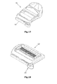
- Figs. 15 to 18 illustrate various objects usable with the plug member or the socket member according to the present invention.
- the plug member or the socket member may be selectively applied on a per object basis.
- FIG. 15 illustrates an alternative embodiment of the present invention in which the connecting device of the present invention is applied to straps, such as belts or bands, provided at backpacks, etc.
- the belts or bands are attached to backpacks or school bags.
- various functional belts or bands such as a shoulder band, a chest band, and a waist belt, are used for different purposes.
- the term "strap" refers to one of the above mentioned various belts and bands.
- a plug member 130 serving as a male member and a socket member 230 serving as a female member are integrally formed with fixing plates 31 and 32 and in turn, the fixing plates 31 and 32 are attached respectively to different straps S1 and S2 to enable separable connection of both the straps Sl and S2.
- the two straps S1 and S2 can be simply connected to each other without other connectors.
- Fig. 16 illustrates an alternative embodiment of the present invention in which the connecting device of the present invention is applied to buckles installed to ends of two straps, such as belts or bands, attached to articles, such as backpacks, school bags, or helmets, to connect or separate the two straps to or from each other.
- the buckles include a male buckle 41 and a female buckle 42, and a plug member 140 is provided at the male buckle 41.
- Figs. 17 and 18 illustrate different appurtenances 51 and 52 that are mainly used with straps, such as belts or bands, provided at bags or backpacks according to alternative embodiments of the present invention.
- each of the appurtenances 51 and 52 is provided with a plug member 151 or 152.
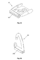
- Figs. 19 to 27 illustrate different appurtenances 61 to 69 provided with various shapes of socket members according to alternative embodiments of the present invention.
- socket members 261 to 269 are provided at the appurtenances 61 to 69, such as hooks, elevating buckles, various strap adjustors, and buckles.
- Fig. 28 illustrates a use example in which shoulder straps of a backpack are connected to each other by chest straps.
- the connecting device according to the present invention is applicable to various appurtenances. More specifically, one of the chest straps is provided with a whistle 71 and in turn, the whistle 71 is formed with the socket member 42 such that a male buckle 41 formed with the plug member 41 is fastened to the whistle 71.
- An opposite end of each chest strap is provided with an elevating buckle having the socket member according to the present invention such that the socket member is connected to the plug member sewed to the associated shoulder strap.
- the present invention provides a device for connecting a strap and an appurtenance to each other, which realizes connection of straps or various associated appurtenances via a simple fitting operation and can maintain a firmly coupled state thereof.
- the connecting device of the strap and the appurtenance is free from abrasion despite repeated use thereof and thus, can stably maintain the coupling of the strap and the appurtenance for a long time.
- the connecting device of the strap and the appurtenance according to the present invention can achieve use convenience via simple operation thereof and has no risk of unintentional separation, resulting in stable use thereof.
Abstract
Disclosed is a connecting device of a strap and an appurtenance. The connecting device includes a plug member and a socket member, which are installed to different objects to be connected to each other. The plug member and the socket member are coupled to each other via coupling of a rail and a rail groove. The rail has an elastic free end to enable elastic coupling or separation thereof.
Description
- The present invention relates to a device for connecting a strap and an associated appurtenance to each other, which enables convenient connection or separation of straps or various associated appurtenances provided at backpacks, bags, garments, helmets, and the like.
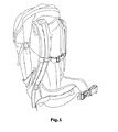
- A variety of appurtenances have been mounted and used at backpacks, bags, caps, garments, and the like as needed. In an example, as illustrated in
Fig. 1 , a backpack is provided at several positions with a great number of straps in such a manner that one end of each strap is fixed to the backpack by sewing, and various shapes of appurtenances, such as adjustors and hooks, are connected to the straps so as to be used per different functions thereof. The backpack is further provided with, e.g., fastening belts and belt buckles. - When being used for a specific activity such as camping, mounting climbing, or the like, a greater number of appurtenances, such as a lantern, cup, alpenstock, and canteen, may be suspended from and carried by the backpack.
- Although all the above mentioned appurtenances are necessary for outdoor activities, unstable suspension and carriage is aesthetically unpleasant and also, restrains person's actions.
- In addition, in the case of the great number of straps basically provided at the backpack, one end of each strap is fixed to the backpack by sewing, whereas the other end of the strap hangs for connection of another strap or appurtenance. However, the hanging ends of most of the straps are not used, and a variety of appurtenances for connection or adjustment of the straps cause an appearance of the backpack to be aesthetically unpleasant. Moreover, since the appurtenances are disorderly arranged, the appurtenances may be easily caught by peripheral objects upon carriage, thus causing inconvenience in person's actions or an accident in the worst case.
- Such straps or appurtenances attached to backpacks or bags provide only limited functions at fixed positions thereof and have no compatibility with other appurtenances having different functions.
- Conventionally, connection between a general strap and several associated appurtenances has been realized, for example, in such a manner that the strap is inserted into and wound around one or more slots perforated in each appurtenance in various ways and in turn, male and female buckles, which are adapted for individual cases, are used to connect the appurtenances to each other. However, it has been found that the above described conventional connection is significantly troublesome and unstable.
- The above described conventional connection results in an increase in the number of appurtenances and manufacturing costs and has limits to realize an orderly and aesthetically pleasing appearance and convenient use.
- Therefore, the present invention has been made in view of the above problems, and it is an object of the present invention to provide a device for connecting a strap and an appurtenance to each other, which enables convenient attachment/detachment of straps or various associated appurtenances provided at backpacks, etc., thus enabling selective use thereof as occasion demands while maintaining a stable operational status of each appurtenance without abrasion despite repeated connection/separation operations.
- It is another object of the present invention to provide a device for connecting a strap and an appurtenance to each other, which assures firm connection of straps or various associated appurtenances provided at backpacks, etc., resulting in safe use of the backpack.
- In accordance with the present invention, the above and other objects can be accomplished by the provision of a connecting device of a strap and an appurtenance including a plug member including an elongated rail formed at one end thereof with a stopper and a rail support connected to a side surface of the rail, and a socket member including a rail groove configured to receive the rail, a socket longitudinally formed from an entrance of the rail groove, and a retaining hole formed in one end thereof to receive the stopper when the rail is fitted into the rail groove, wherein the end of the rail is spaced apart from the rail support to define an elastic free end, and the stopper is located in a range of the free end.
- Accordingly, it is possible to allow the stopper to be stably caught by the retaining hole in the course of fitting the rail into the rail groove. Also, the rail is able to be separated from the rail groove in a state wherein the stopper is released from the retaining hole as the free end is elastically pushed. This assures smooth separation of the rail without friction between the stopper and the rail groove.
- To space the free end of the rail apart from the rail support, the free end of the rail may protrude outward beyond the rail support.
- This provides the free end of the rail with elasticity, enabling elastic displacement of the stopper included in the free end.
- Alternatively, the rail and the rail support may have the same length and a separation space may be defined between the free end of the rail and the rail support. This provides the free end of the rail with elasticity, enabling elastic displacement of the stopper included in the free end.
- The free end of the rail may be thinner than a remaining region of the rail to enhance elasticity thereof. A grip may be formed at a distal position of the free end and may take the form of an expanded portion.
- The stopper included in the free end may have an inclined surface facing a fixed end of the rail and a vertical surface facing the free end of the rail. The inclined surface of the stopper assures smooth coupling of the rail and the rail groove and the vertical surface of the stopper maintains a firmly coupled state of the rail and the rail groove.
- The above and other objects, features and other advantages of the present invention will be more clearly understood from the following detailed description taken in conjunction with the accompanying drawings, in which:
- Fig. 1
- is a perspective view illustrating an exemplary conventional backpack;
- Fig. 2
- is an exploded perspective view of a connecting device according to an embodiment of the present invention;
- Fig. 3
- is a plan view of a plug member illustrated in
Fig. 2 ; - Fig. 4
- is a front view of the plug member illustrated in
Fig. 3 ; - Fig. 5
- is a plan view illustrating a plug member according to an alternative embodiment of the present invention;
- Fig. 6
- is a front view of the plug member illustrated in
Fig. 5 ; - Fig. 7
- is a sectional view illustrating a rail of a plug member according to an alternative embodiment of the present invention;
- Fig. 8
- is a perspective view illustrating a plug member according to an alternative embodiment of the present invention;
- Fig. 9
- is a plan view of the plug member illustrated in
Fig. 8 ; - Fig. 10
- is a sectional view taken line C-C of
Fig. 8 ; - Fig. 11
- is a sectional view illustrating a rail of a plug member according to an alternative embodiment of the present invention;
- Figs. 12 to 14
- are sectional views illustrating an operation of the connecting device according to the present invention;
- Fig. 15
- is a perspective view illustrating a plug member and a socket member for connection of different straps according to an alternative embodiment of the present invention;
- Fig. 16
- is a perspective view illustrating a plug member and a socket member for connection of buckles according to an alternative embodiment of the present invention;
- Figs. 17 and 18
- are perspective views illustrating different appurtenances provided with a plug member according to alternative embodiments of the present invention;
- Figs. 19 to 27
- are perspective views illustrating different appurtenances provided with a socket member according to alternative embodiments of the present invention; and
- Fig. 28
- is a view illustrating a use example in which shoulder straps of a backpack are connected to each other by chest straps.
- Hereinafter, preferred embodiments of the present invention will be described in detail with reference to the accompanying drawings.
-
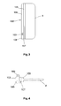
Fig. 2 is an exploded perspective view of a connecting device according to an embodiment of the present invention,Fig. 3 is a plan view of a plug member illustrated inFig. 2 , andFig. 4 is a front view of the plug member illustrated inFig. 3 . Referring to the drawings, the connecting device according to the present invention includes aplug member 100 serving as a male member and asocket member 200 serving as a female member. Theplug member 100 and thesocket member 200 are provided at respective ends of a first object A and a second object B, so as to be connected to or separated from each other. - In the drawings, the first object A and the second object B are illustrated as being thin fixing plates according to an exemplary configuration of the present embodiment. The fixing plates are made of synthetic resins and are adapted to be attached to, e.g., garments, belts, backpacks, bags, and various straps by sewing.
- The
plug member 100 includes arail support 101 and arail 102. Therail support 101 is integrally formed with the first object A. - The
rail 102 protrudes from an outer edge of therail support 101 to define a movement path having a predetermined width. Astopper 103 protrudes from one end of therail 102. In the present embodiment, thestopper 103 has avertical surface 104 facing a free end of therail 102 and aninclined surface 105 facing an opposite fixed end of therail 102. - The movement path of the
rail 102 is preferably a straight path, but may be a curved path. - The
socket member 200 to be coupled with theplug member 100 is integrally formed at one end of the second object B. Thesocket member 200 has an elongatedrail groove 202 into which therail 102 of theplug member 100 can be fitted. Therail groove 202 is defined in one end thereof with a C-shapedentrance 204, through which one end of therail 102 begins to be fitted. Thesocket member 200 also has an elongatedslot 205 having the same length as therail groove 202 starting from an open end of the C-shapedentrance 204. - The
entrance 204 of therail groove 202 preferably has the same contour as a lateral contour of therail 102. Theslot 205 has a smaller width than that of therail groove 202 and functions as a passage for movement of therail support 101. - Although the
slot 205 may be selectively formed in a side surface, upper surface or lower surface of therail groove 202, theslot 205 preferably has a shape corresponding to a connecting structure of therail 102 and therail support 101. - A retaining
hole 203 corresponding to thestopper 103 of therail 102 is provided near one end of therail groove 202. When therail 102 is completely fitted into therail groove 202, thestopper 103 is inserted into the retaininghole 203 to maintain a coupled state of therail 102 and therail groove 202. The other end of therail groove 202 opposite to theentrance 204 may be closed to define aclosure wall 206. In this case, once theplug member 100 and thesocket member 200 are coupled with each other, it is possible to prevent therail 102 from escaping from therail groove 202 even if therail 102 is forcibly pushed against resistance of thestopper 103. Specifically, theclosure wall 206 sets a movement limit when therail 102 is pushed in a given direction so as to be fitted into therail groove 202 and also, functions to stably limit a coupling position of therail 102. - One end of the
rail 102 of theplug member 100 is spaced apart from therail support 101 and defines afree end 106 having elasticity. Thestopper 103 is located in a range of thefree end 106. - More specifically, as illustrated in the drawings, a
separation space 107 is defined between therail support 101 and one end of therail 102 and a remaining region of therail 102 except for the end of therail 102 comes into contact with therail support 101. With provision of theseparation space 107, the end of therail 102 is separated from therail support 101 so as to define thefree end 106 and the remaining region of therail 102 is connected to therail support 101 so as to define the fixed end of therail 102. Thefree end 106 has elasticity. - With this configuration, the elastic
free end 106 of therail 102 may act to minimize frictional resistance caused when thestopper 103 comes into contact with an inner periphery of the retaininghole 203 in the course of fitting therail 102 into therail groove 202. -
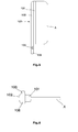
Figs. 5 and 6 illustrate an alternative configuration of the free end of the rail. Referring toFigs. 5 and 6 , one end of therail 102 of theplug member 100 protrudes outward beyond therail support 101 to define thefree end 106. Thestopper 103 is located in a range of thefree end 106. - Referring to
Fig. 7 in a sectional view, in order to provide thefree end 106 of therail 102 according to the present invention with sufficient elasticity, thefree end 106 of therail 102 is thinner than the remaining region of therail 102. - As will be appreciated from the above described embodiments of the present invention related to different configurations of the free end of the rail, the free end is defined at an opposite side of a leading end of the rail that begins to be fitted into the rail groove of the socket member.
-
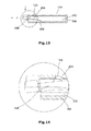
Figs. 8 to 10 are views illustrating an alternative embodiment of the present invention in which a grip is provided at the free end of the rail. In the drawings, agrip 108 is attached to thefree end 106 of therail 102 of theplug member 100 and takes the form of an expanded plate. The expanded plate-shapedgrip 108 has concave upper and lower surfaces to assure a stable grip operation. -
Fig. 11 illustrates an alternative configuration of the grip provided at the free end of the rail. As illustrated, thegrip 108 may take the form of an expanded portion extending from thefree end 106 of therail 102 and the upper surface of thegrip 108 may be inclined such that an outer end thereof protrudes upward. - The above described configurations of the
grip 108 have the effect of allowing thegrip 108 provided at thefree end 106 of therail 102 to stably come into contact with and be caught by a user's finger tip when a user operates thefree end 106 with his/her finger. In particular, when it is desired to separate theplug member 100 from thesocket member 200, the user is able to easily pull thesocket member 200 out by pushing and pulling thegrip 108 with his/her finger. - In an alternative embodiment of the present invention, two or more retaining
holes 203 may be provided in therail groove 202 of thesocket member 200 to enable selective insertion of thestopper 103 and consequently, to allow theplug member 100 to be fixed at an arbitrary position. Each of the retaining holes 203 has an open end to be connected to theslot 205. -
Figs. 12 to 14 illustrate an operation of the above described connecting device according to the present invention. Referring to the drawings, therail 102 of theplug member 100 is longitudinally fitted into therail groove 202 of thesocket member 200. Therail 102 is fitted into therail groove 202 via smooth sliding motion thereof. Thestopper 103 is moved while coming into contact with an inner surface of therail groove 202 and is smoothly inserted into and elastically caught by the retaininghole 203 without friction owing to elastic bending of thefree end 106 of therail 102. - Specifically, the
inclined surface 105 of thestopper 103 facing the fixed end of therail 102 realizes smooth insertion of thestopper 103. On the other hand, once thevertical surface 104 of thestopper 103 facing the oppositefree end 106 of therail 102 is caught by the retaininghole 203, thevertical surface 104 makes it difficult for thestopper 103 to be moved backward, thus preventing unintentional separation of thestopper 103. - With the coupling of the
rail 102 and therail groove 202, the first object A and the second object B, to which theplug member 100 and thesocket member 200 are integrally formed respectively, can be simply connected to each other. - When it is desired to separate the
plug member 100 and thesocket member 200 from each other, thestopper 103 escapes from the retaininghole 203 as thefree end 106 of therail 102 is pushed to overcome elasticity thereof and simultaneously, theplug member 100 is pulled out of therail groove 202 of thesocket member 200 so as to be separated from thesocket member 200.Figs. 15 to 18 illustrate various objects usable with the plug member or the socket member according to the present invention. The plug member or the socket member may be selectively applied on a per object basis. - Firstly,
Fig. 15 illustrates an alternative embodiment of the present invention in which the connecting device of the present invention is applied to straps, such as belts or bands, provided at backpacks, etc. - Here, the belts or bands are attached to backpacks or school bags. In the case of a backpack, various functional belts or bands, such as a shoulder band, a chest band, and a waist belt, are used for different purposes. In the following description, the term "strap" refers to one of the above mentioned various belts and bands.
- In the embodiment as illustrated in
Fig. 15 , aplug member 130 serving as a male member and asocket member 230 serving as a female member are integrally formed with fixingplates plates - That is, with the
plug member 130 and thesocket member 230 provided at the different straps S1 and S2, the two straps S1 and S2 can be simply connected to each other without other connectors. -
Fig. 16 illustrates an alternative embodiment of the present invention in which the connecting device of the present invention is applied to buckles installed to ends of two straps, such as belts or bands, attached to articles, such as backpacks, school bags, or helmets, to connect or separate the two straps to or from each other. In the embodiment as illustrated inFig. 16 , the buckles include amale buckle 41 and afemale buckle 42, and aplug member 140 is provided at themale buckle 41. -
Figs. 17 and 18 illustrate different appurtenances 51 and 52 that are mainly used with straps, such as belts or bands, provided at bags or backpacks according to alternative embodiments of the present invention. In the drawings, each of the appurtenances 51 and 52 is provided with aplug member 151 or 152. These embodiments are given by way of example and functions and configurations thereof are applicable in various ways. -
Figs. 19 to 27 illustrate different appurtenances 61 to 69 provided with various shapes of socket members according to alternative embodiments of the present invention. Referring to the drawings,socket members 261 to 269 are provided at the appurtenances 61 to 69, such as hooks, elevating buckles, various strap adjustors, and buckles. These embodiments are also given by way of example and functions and configurations thereof are applicable in various ways. -
Fig. 28 illustrates a use example in which shoulder straps of a backpack are connected to each other by chest straps. As illustrated inFig. 28 , the connecting device according to the present invention is applicable to various appurtenances. More specifically, one of the chest straps is provided with awhistle 71 and in turn, thewhistle 71 is formed with thesocket member 42 such that amale buckle 41 formed with theplug member 41 is fastened to thewhistle 71. An opposite end of each chest strap is provided with an elevating buckle having the socket member according to the present invention such that the socket member is connected to the plug member sewed to the associated shoulder strap. - As apparent from the above description, the present invention provides a device for connecting a strap and an appurtenance to each other, which realizes connection of straps or various associated appurtenances via a simple fitting operation and can maintain a firmly coupled state thereof.
- Further, the connecting device of the strap and the appurtenance is free from abrasion despite repeated use thereof and thus, can stably maintain the coupling of the strap and the appurtenance for a long time.
- Furthermore, the connecting device of the strap and the appurtenance according to the present invention can achieve use convenience via simple operation thereof and has no risk of unintentional separation, resulting in stable use thereof.
- Although the preferred embodiments of the present invention have been disclosed for illustrative purposes, those skilled in the art will appreciate that various modifications, additions and substitutions are possible, without departing from the scope and spirit of the invention as disclosed in the accompanying claims.
Claims (10)
- A connecting device of a strap and an appurtenance comprising:a plug member including an elongated rail formed at one end thereof with a stopper and a rail support connected to a side surface of the rail; anda socket member including a rail groove configured to receive the rail, a socket longitudinally formed from an entrance of the rail groove, and a retaining hole formed in one end thereof to receive the stopper when the rail is fitted into the rail groove,wherein the end of the rail is spaced apart from the rail support to define an elastic free end, and the stopper is located in a range of the free end of the rail so as to be released from the retaining hole when the free end is pushed to separate the plug member from the socket member.
- The connecting device according to claim 1, wherein a separation space is defined between the free end of the rail and the rail support.
- The connecting device according to claim 1, wherein the free end is thinner than a fixed end of the rail integrally formed with the rail support, so as to enhance elasticity thereof.
- The connecting device according to claim 3, wherein the stopper has an inclined surface facing the fixed end of the rail, and a vertical surface facing the free end of the rail.
- The connecting device according to claim 1, wherein a grip is formed at a distal position of the free end and has a larger expanded shape than a cross section of the rail, and a surface of the grip is formed with a concave recess.
- The connecting device according to claim 1, wherein a thin fixing plate extends rearward from the rail support of the plug member and is sewed to an object along with the plug member, and an object having the socket member is connected to the rail of the plug member sewed at a fixed position.
- The connecting device according to claim 1, wherein a thin fixing plate extends rearward from a surface of the socket member and is sewed to an object along with the socket member, and an object having the plug member is connected to the rail groove of the socket member sewed at a fixed position.
- The connecting device according to claim 1, wherein the plug member or the socket member integrally protrudes from one end of the strap or the appurtenance, the strap and the appurtenance being objects to be connected to each other.
- The connecting device according to claim 8, wherein the appurtenance is a strap adjustor or a backpack buckle to be connected to the strap so as to adjust a length of the strap or to be connected to another strap appurtenance.
- The connecting device according to claim 8, wherein the strap appurtenance is a hook to enable connection of a variety of articles.
Applications Claiming Priority (1)
| Application Number | Priority Date | Filing Date | Title |
|---|---|---|---|
| KR20100004130A KR101064014B1 (en) | 2010-01-16 | 2010-01-16 | Straps and Attachments |
Publications (1)
| Publication Number | Publication Date |
|---|---|
| EP2363034A1 true EP2363034A1 (en) | 2011-09-07 |
Family
ID=44259709
Family Applications (1)
| Application Number | Title | Priority Date | Filing Date |
|---|---|---|---|
| EP10157213A Withdrawn EP2363034A1 (en) | 2010-01-16 | 2010-03-22 | Connecting device of strap and appurtenance |
Country Status (2)
| Country | Link |
|---|---|
| EP (1) | EP2363034A1 (en) |
| KR (1) | KR101064014B1 (en) |
Cited By (7)
| Publication number | Priority date | Publication date | Assignee | Title |
|---|---|---|---|---|
| WO2013109587A1 (en) * | 2012-01-18 | 2013-07-25 | Illinois Tool Works Inc. | Locking connector assembly |
| US20140332572A1 (en) * | 2011-11-18 | 2014-11-13 | FirstSpear, LLC | Garment assembly and release apparatus and method |
| FR3006153A1 (en) * | 2013-06-03 | 2014-12-05 | Protecop | FIXING SYSTEM FOR PROTECTIVE EQUIPMENT, COMPRISING A MALE FASTENER AND A FEMALE FASTENER |
| EP3228205A1 (en) * | 2016-04-05 | 2017-10-11 | Mrm Hk Limited | Buckle |
| CN109938443A (en) * | 2017-12-21 | 2019-06-28 | 贝尔运动股份有限公司 | Goggles with replaceable cingulum |
| WO2020172507A1 (en) * | 2019-02-21 | 2020-08-27 | Ossur Iceland Ehf | Interchangeable attachment device |
| US11911673B2 (en) | 2015-03-02 | 2024-02-27 | Karsten Manufacturing Corporation | Golf bag with collapsable pocket assembly |
Citations (6)
| Publication number | Priority date | Publication date | Assignee | Title |
|---|---|---|---|---|
| US3979801A (en) * | 1974-11-15 | 1976-09-14 | Georges Tareau | Fastening device to be used for doing-up a brassiere |
| JPS5590309U (en) * | 1978-12-18 | 1980-06-21 | ||
| JPS55173914U (en) * | 1979-05-31 | 1980-12-13 | ||
| JPS5768608U (en) * | 1980-10-14 | 1982-04-24 | ||
| EP0095656A2 (en) | 1982-05-28 | 1983-12-07 | American Cord & Webbing Co., Inc. | Buckle |
| US4790050A (en) * | 1987-04-13 | 1988-12-13 | Yoshida Kogyo K. K. | Pull tab for slide fastener slider |
Family Cites Families (2)
| Publication number | Priority date | Publication date | Assignee | Title |
|---|---|---|---|---|
| KR100547406B1 (en) | 2004-09-30 | 2006-01-31 | 백남일 | Lifting buckle for baekpack strap |
| JP2009078123A (en) | 2007-09-07 | 2009-04-16 | Morito Co Ltd | Connection method of installation part and installation object |
-
2010
- 2010-01-16 KR KR20100004130A patent/KR101064014B1/en active IP Right Grant
- 2010-03-22 EP EP10157213A patent/EP2363034A1/en not_active Withdrawn
Patent Citations (6)
| Publication number | Priority date | Publication date | Assignee | Title |
|---|---|---|---|---|
| US3979801A (en) * | 1974-11-15 | 1976-09-14 | Georges Tareau | Fastening device to be used for doing-up a brassiere |
| JPS5590309U (en) * | 1978-12-18 | 1980-06-21 | ||
| JPS55173914U (en) * | 1979-05-31 | 1980-12-13 | ||
| JPS5768608U (en) * | 1980-10-14 | 1982-04-24 | ||
| EP0095656A2 (en) | 1982-05-28 | 1983-12-07 | American Cord & Webbing Co., Inc. | Buckle |
| US4790050A (en) * | 1987-04-13 | 1988-12-13 | Yoshida Kogyo K. K. | Pull tab for slide fastener slider |
Cited By (18)
| Publication number | Priority date | Publication date | Assignee | Title |
|---|---|---|---|---|
| EP3136041A1 (en) * | 2011-11-18 | 2017-03-01 | FirstSpear, LLC | Garment assembly and release apparatus and method |
| US20140332572A1 (en) * | 2011-11-18 | 2014-11-13 | FirstSpear, LLC | Garment assembly and release apparatus and method |
| US10051984B2 (en) * | 2011-11-18 | 2018-08-21 | FirstSpear, LLC | Garment assembly and release apparatus and method |
| EP2780656A4 (en) * | 2011-11-18 | 2015-05-06 | Firstspear | Garment assembly and release apparatus and method |
| US10316887B2 (en) | 2012-01-18 | 2019-06-11 | Illinois Tool Works, Inc. | Locking connector assembly |
| US11473614B2 (en) | 2012-01-18 | 2022-10-18 | Illinois Tool Works Inc. | Locking connector assembly |
| WO2013109587A1 (en) * | 2012-01-18 | 2013-07-25 | Illinois Tool Works Inc. | Locking connector assembly |
| FR3006153A1 (en) * | 2013-06-03 | 2014-12-05 | Protecop | FIXING SYSTEM FOR PROTECTIVE EQUIPMENT, COMPRISING A MALE FASTENER AND A FEMALE FASTENER |
| US11911673B2 (en) | 2015-03-02 | 2024-02-27 | Karsten Manufacturing Corporation | Golf bag with collapsable pocket assembly |
| CN107259717A (en) * | 2016-04-05 | 2017-10-20 | Mrm香港有限公司 | Hasp |
| CN107259717B (en) * | 2016-04-05 | 2020-07-07 | Mrm香港有限公司 | Hasp |
| EP3228205A1 (en) * | 2016-04-05 | 2017-10-11 | Mrm Hk Limited | Buckle |
| CN109938443A (en) * | 2017-12-21 | 2019-06-28 | 贝尔运动股份有限公司 | Goggles with replaceable cingulum |
| EP3510980A1 (en) * | 2017-12-21 | 2019-07-17 | Bell Sports, Inc. | Goggles with interchangeable locking strap |
| CN109938443B (en) * | 2017-12-21 | 2022-02-25 | 贝尔运动股份有限公司 | Goggles with replaceable buckle |
| US11517479B2 (en) | 2017-12-21 | 2022-12-06 | Bell Sports, Inc. | Goggles with interchangeable locking strap |
| US11850189B2 (en) | 2017-12-21 | 2023-12-26 | Bell Sports, Inc. | Goggles with interchangeable locking strap |
| WO2020172507A1 (en) * | 2019-02-21 | 2020-08-27 | Ossur Iceland Ehf | Interchangeable attachment device |
Also Published As
| Publication number | Publication date |
|---|---|
| KR20110084348A (en) | 2011-07-22 |
| KR101064014B1 (en) | 2011-09-08 |
Similar Documents
| Publication | Publication Date | Title |
|---|---|---|
| EP2363034A1 (en) | Connecting device of strap and appurtenance | |
| US9936772B2 (en) | Buckle for chest strap of knapsack | |
| US9538833B2 (en) | Assembly for storing and deploying for use a handheld digital device | |
| KR101030366B1 (en) | coupling device of strap and appurtenance | |
| US9851758B2 (en) | Assembly for storing and deploying for use a handheld digital device | |
| US9439515B2 (en) | Sliding device, baby carrier, knapsack, bag, and belt bag | |
| US5732861A (en) | Baby carrying harness and clasp means therefor | |
| EP3165118A1 (en) | Buckle | |
| US9737122B1 (en) | Convertible backpack handbag | |
| US20090235435A1 (en) | Tensioning device for clothing straps | |
| US20130168428A1 (en) | Sling bag with strap fastening arrangement | |
| US8387182B2 (en) | Device for hanging a holster along a mattress | |
| US7407430B1 (en) | Adjustable front closure for bra or bikini top | |
| US5950897A (en) | Storage box | |
| US8959722B2 (en) | Apparatus for comfortably hanging keys and other key-ring accessories within a slash-type clothing pocket | |
| CN201045910Y (en) | Zipper head structure with two-sided button | |
| US10470527B2 (en) | Rope tail positioning fastener | |
| US20150150358A1 (en) | Hanging belt | |
| US9282808B1 (en) | Hanger assembly for attaching articles to fabric | |
| US20160296726A1 (en) | Support for holding the external device of a peritoneal dialysis catheter, and additional system for attaching the support | |
| KR20110099843A (en) | Coupling device of strap and appurtenance | |
| CN214340265U (en) | Dual-purpose hanging rope combination for mask | |
| CN218303498U (en) | Garment with detachable multifunctional patch pocket | |
| CN109700162A (en) | Chest strap | |
| KR102461057B1 (en) | buckle for backpack with improved fastening force |
Legal Events
| Date | Code | Title | Description |
|---|---|---|---|
| PUAI | Public reference made under article 153(3) epc to a published international application that has entered the european phase |
Free format text: ORIGINAL CODE: 0009012 |
|
| AK | Designated contracting states |
Kind code of ref document: A1 Designated state(s): AT BE BG CH CY CZ DE DK EE ES FI FR GB GR HR HU IE IS IT LI LT LU LV MC MK MT NL NO PL PT RO SE SI SK SM TR |
|
| AX | Request for extension of the european patent |
Extension state: AL BA ME RS |
|
| 17P | Request for examination filed |
Effective date: 20120303 |
|
| 17Q | First examination report despatched |
Effective date: 20131031 |
|
| STAA | Information on the status of an ep patent application or granted ep patent |
Free format text: STATUS: THE APPLICATION HAS BEEN WITHDRAWN |
|
| 18W | Application withdrawn |
Effective date: 20160113 |