EP2362708B1 - Verfahren zur Durchführung einer Direktzugriffsprozedur durch einen Relaisknoten in einem Drahtlos- oder Funkkommunikationsnetzwerk, zugehöriger Relaisknoten - Google Patents
Verfahren zur Durchführung einer Direktzugriffsprozedur durch einen Relaisknoten in einem Drahtlos- oder Funkkommunikationsnetzwerk, zugehöriger Relaisknoten Download PDFInfo
- Publication number
- EP2362708B1 EP2362708B1 EP10305151A EP10305151A EP2362708B1 EP 2362708 B1 EP2362708 B1 EP 2362708B1 EP 10305151 A EP10305151 A EP 10305151A EP 10305151 A EP10305151 A EP 10305151A EP 2362708 B1 EP2362708 B1 EP 2362708B1
- Authority
- EP
- European Patent Office
- Prior art keywords
- random access
- relay node
- link
- access procedure
- backhaul link
- Prior art date
- Legal status (The legal status is an assumption and is not a legal conclusion. Google has not performed a legal analysis and makes no representation as to the accuracy of the status listed.)
- Not-in-force
Links
Images

Classifications
-
- H—ELECTRICITY
- H04—ELECTRIC COMMUNICATION TECHNIQUE
- H04W—WIRELESS COMMUNICATION NETWORKS
- H04W84/00—Network topologies
- H04W84/02—Hierarchically pre-organised networks, e.g. paging networks, cellular networks, WLAN [Wireless Local Area Network] or WLL [Wireless Local Loop]
- H04W84/04—Large scale networks; Deep hierarchical networks
- H04W84/042—Public Land Mobile systems, e.g. cellular systems
- H04W84/045—Public Land Mobile systems, e.g. cellular systems using private Base Stations, e.g. femto Base Stations, home Node B
-
- H—ELECTRICITY
- H04—ELECTRIC COMMUNICATION TECHNIQUE
- H04B—TRANSMISSION
- H04B7/00—Radio transmission systems, i.e. using radiation field
- H04B7/14—Relay systems
- H04B7/15—Active relay systems
- H04B7/155—Ground-based stations
- H04B7/15557—Selecting relay station operation mode, e.g. between amplify and forward mode, decode and forward mode or FDD - and TDD mode
-
- H—ELECTRICITY
- H04—ELECTRIC COMMUNICATION TECHNIQUE
- H04W—WIRELESS COMMUNICATION NETWORKS
- H04W74/00—Wireless channel access, e.g. scheduled or random access
- H04W74/08—Non-scheduled or contention based access, e.g. random access, ALOHA, CSMA [Carrier Sense Multiple Access]
- H04W74/0866—Non-scheduled or contention based access, e.g. random access, ALOHA, CSMA [Carrier Sense Multiple Access] using a dedicated channel for access
- H04W74/0891—Non-scheduled or contention based access, e.g. random access, ALOHA, CSMA [Carrier Sense Multiple Access] using a dedicated channel for access for synchronized access
-
- H—ELECTRICITY
- H04—ELECTRIC COMMUNICATION TECHNIQUE
- H04W—WIRELESS COMMUNICATION NETWORKS
- H04W84/00—Network topologies
- H04W84/02—Hierarchically pre-organised networks, e.g. paging networks, cellular networks, WLAN [Wireless Local Area Network] or WLL [Wireless Local Loop]
- H04W84/04—Large scale networks; Deep hierarchical networks
- H04W84/042—Public Land Mobile systems, e.g. cellular systems
- H04W84/047—Public Land Mobile systems, e.g. cellular systems using dedicated repeater stations
Definitions
- the present invention relates to the field of telecommunication, and more specifically to a method for performing a random access procedure by a relay node in a wireless or radio communication network.
- Relay-based wireless or radio communication network are gaining in interest thanks to the possibility of reaching enhanced coverage while keeping the energy required in addition in range. More precisely, coverage of high data rates, group mobility, temporary network deployment cell edge throughput and/or coverage in new areas are subjects which can be greatly improved by introducing relays in conventional wireless/radio communication networks.
- Such relays based wireless or radio communication networks are especially being investigated in the framework of 3GPP LTE (Long Term Evolution) or IEEE 802.16 i /m standardization initiatives.
- Figure 1 is showing the general architecture of relay-based wireless/radio communication networks where a user equipment UE no more communicates directly with a base station eNB but where a relay node RN is included in the path between user equipment UE and base station eNB. Consequently, relay node RN is wirelessly connected to base station eNB also called donor cell or donor eNB over a backhaul link also called Un interface in the context of 3GPP LTE standardization and relay node is wirelessly connected to user equipment UE over an access link also called Uu interface in the context of 3GPP LTE standardization.
- base station eNB also called donor cell or donor eNB over a backhaul link also called Un interface in the context of 3GPP LTE standardization
- relay node is wirelessly connected to user equipment UE over an access link also called Uu interface in the context of 3GPP LTE standardization.
- inband operation consists in that the backhaul link shares the same band as the link used for direct communication between the user equipment UE and the base station eNB.
- outband operation consists in that the backhaul link operates in a different band that the one used for direct link between the user equipment and the base station.
- a type 1 relay node controls a cell which appears to the user equipment as a cell distinct from the donor cell.
- the relay node has consequently its own physical cell id and transmits its own synchronization channel and reference symbols, as such it appears as a base station eNB to the user equipments.
- the relay transmitter would cause interference on its relay receiver if they are active simultaneously and/or if not sufficient isolation of the incoming and outgoing signals are provided. This self interference issue is especially problematic for random access procedures performed by the relay node.
- RA Random Access
- the Random Access Procedure consists in sending in an uplink channel (Random Access Channel RACH) control information from a user equipment/or relay node to the network.
- RACH Random Access Channel
- the RACH channel is a contention based channel where several user equipment/relays might access the same resource.
- the network answers with a random access response which is comprised within a flexible time window configured by the base station and contains at least uplink grant on resources available between the user equipment and the base station so that the user equipment can schedule transmission on the granted uplink resources.
- the random access procedure in situations 1 to 5 occurs when the relay node is already operating on the access link. Unfortunately, the usual random access procedure on the backhaul link will interfere with the operation on the access link so that it is necessary for the relay node to stop all communication on the access link interface while performing the random access procedure on the backhaul link.
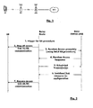
- FIG. 2 An illustration of the flow diagram of the currently possible random access procedure by the relay node while in service to user equipment UE already attached to the relay node is illustrated on figure 2 .
- a step 1 consists in detecting at the relay node RN one of the situations 1) to 5) in which a random access procedure should be triggered
- Step 2 consists in stopping all uplink and downlink communication on the access link with user equipments
- Step 3 consists in sending a random access preamble on the Random Access Channel
- Step 4 consists in receiving from the base station a random access response which is comprised within a flexible time window configured by the base station and contains at least uplink grant on resources available between the user equipment and the base station so that the user equipment can schedule transmission on the granted uplink resources
- Step 5 consists in sending a scheduled transmission message on the granted uplink resources
- Step 6 consists in a resource configuration message sent to the relay node indicating a new resource configuration valid for the communication on the backhaul link from this time on.
- the relay node Even if the time of the random access preamble transmission in step 3 is well defined by the random access procedure (PRACH configuration), the relay node should expect the reception of messages 4 and 6 at any time not further precisely defined by the usual random access procedure. Also the relay node should expect to transmit the message 3 at any time on the granted uplink resources. That is why to avoid interference with message 4 and 6 on the access link it is necessary to stop the communication on the access link.
- PRACH configuration the random access procedure
- the user equipment will experience sudden and long interruptions of the service.
- the duration of the interruption will be equal to the time necessary to configure the stopping of the access link, the time to configure the resuming of the access link and the time necessary to the perform the random access procedure.
- a particular object of the present invention is to provide for a solution to reduce the interruption time on the access link while the relay node is to perform a random access procedure on the backhaul link.
- Another object of the invention is to provide a relay node and a base station adapted to support such mechanisms.
- the present invention is directed to addressing the effects of one or more of the problems set forth above.
- the following presents a simplified summary of the invention in order to provide a basic understanding of some aspects of the invention. This summary is not an exhaustive overview of the invention. It is not intended to identify key or critical elements of the invention or to delineate the scope of the invention. Its sole purpose is to present some concepts in a simplified form as a prelude to the more detailed description that is discussed later.
- a configuration of the resources for the backhaul link and for the access link is performed before the random access procedure starts so that both are time multiplexed.
- This configuration of resources makes sure that there is no interference between the access and the backhaul link.
- messages of the random access procedure are sent on resources configured for the backhaul link between the base station and the relay node.
- the relay node is not communicating with user equipments when it is supposed to receive a random access response from the donor cell.
- this is realized by creating gaps in the access link during which user equipments are not supposed to expect any relay transmission. These gaps can be created by configuring MBSFN sub-frames for sole use by the relay nodes which the user equipments are not expected to follow.
- the backhaul link respectively access link configuration which was used before the random access procedure by the relay node continue to be used so that the relay nodes receives the random access procedure messages on the backhaul interface not simultaneously with the operation on the access link.
- Either the random access response is sent to the sole relay node which has entered the random access procedure or the random access response is sent to a group of relay nodes all having started the random access procedure.
- the method according to the present invention presents the advantage to ensure that the relay node can continue to communicate on the access link without experiencing self interference from the random access procedure until a new configuration of the backhaul link /access link resources is reached at the end of the random access procedure.
- Another advantage of the present invention consists in that the relay node stores any data received on the access link from the user equipments and can resume the data transmission/reception over the backhaul link as soon as the random access procedure according to the present invention has been successfully completed. Consequently, the interruption seen by the user equipment connected to the relay node is negligible.
- any functional blocks labeled as 'processors' may be provided through the use of dedicated hardware as well as hardware capable of executing software in association with appropriate software.
- the functions may be provided by a single dedicated processor, by a single shared processor, or by a plurality of individual processors, some of which may be shared.
- DSP digital signal processor
- ASIC application specific integrated circuit
- FPGA field programmable gate array
- ROM read only memory
- RAM random access memory
- non volatile storage Other hardware, conventional and/or custom, may also be included.
- any boxes shown in the Figures are conceptual only. Their function may be carried out through the operation of program logic, through dedicated logic, through the interaction of program control and dedicated logic, or even manually, the particular technique being selectable by the implementer as more specifically understood from the context.
- Figure 3 shows a random access procedure according to a first embodiment of the present invention.
- Step 31 consists in triggering the random access procedure by the relay node. This triggering is preferably done by sending a random access preamble which is univocally assigned to the relay node on a random access channel at a predefined sub frame of the random access channel defined by PRACH configuration as defined in release 8 random access procedure of 3GPP LTE.
- step 31 consists in triggering the random access procedure by the relay node.
- This triggering is preferably done by sending a random access preamble which is assigned to a group of relay nodes that the relay node belongs to on a random access channel at a predefined sub frame of the random access channel defined by PRACH configuration as defined in release 8 random access procedure of 3GPP LTE.
- step 31 consists in triggering the random access procedure by the relay node. This triggering is preferably done by sending a random access preamble out of a group of random access preambles assigned to a group of relay nodes that the relay node belongs to on a random access channel at a predefined sub frame of the random access channel defined by PRACH configuration as defined in release 8 random access procedure of 3GPP LTE.
- the relay node Since the relay node has the control over the access link, the relay node can ensure that no data are sent or received over the access link while it intends to send its random access preamble over the backhaul link.
- the relay node uses a previously configured resource reserved for communication over the backhaul link.
- the configured resource may be controlled by the base station or alternatively may be determined centrally at an operation and maintenance center and then preferably communicated to both relay node and base station.
- the base station Upon reception of the trigger message, the base station identifies the relay node which has started the random access procedure preferably by mapping the received the random access preamble with the corresponding relay node.
- the base station Upon reception of the trigger message, the base station identifies the group which the relay node belongs to where the relay node has started the random access procedure preferably by mapping the received the random access preamble with the corresponding group of relay nodes.
- Step 32 consists in sending a random access response from the base station to the relay node.
- a MBSFN sub frame is used to convey the random access response.
- the MBSFN sub frame is defined so as to contain broadcast multicast information. Some sub frames are reserved in the context of Release 8 3GPP LTE to contain only MBSFN and are consequently only relevant on the backhaul link. These categories of sub frames are not destined to the user equipments. Only the first 2 control symbols of the MBSFN sub frame may be decoded by the user equipments. Consequently, the relay node in control of the configuration of the access link will not schedule any communication on the access link while MBSFN frames are exchanged on the backhaul link.
- the MBSFN sub-frames are a good example of sub frames fulfilling the condition that no communication takes place on the access link and on the backhaul link simultaneous. This embodiment makes use of already existing sub frames for the sake of an efficient random access procedure.
- the random access response may be sent on the downlink synchronisation channel (DL-SCH) and transmitted on MBSFN sub frames reserved for relay node(s) operation.
- This message could be semi-synchronous with the triggering message of step 31.
- the random access response could be addressed to RA-RNTI (Random Access Radio Network Temporary Identity) on the physical downlink control channel (PDCCH).
- RA-RNTI Random Access Radio Network Temporary Identity
- PDCCH physical downlink control channel
- RA-RNTI is corresponding to the PRACH where the preamble is transmitted; hence it can be received by a group of UE/RN who have transmitted preambles on the corresponding PRACH.
- a group of relay nodes who have transmitted preambles on the corresponding PRACH can receive the random access response transmitted on MBSFN subframes. Therefore, this method can be used to send the random access response message to a group of RNs.
- the random access response message would convey at least:
- Step 33 consists in sending a first scheduled uplink transmission between the relay node and the base station on an uplink resource indicated in the previously received random access response message in step 32.
- the first scheduled UL transmission on UL-SCH preferably uses HARQ, the size of the transport blocks depends on the UL grant conveyed in step 32.
- C-RNTI radio network temporary identity
- FIG. 4 shows the structure of a MBSFN sub-frame as used in combination with the first embodiment of the present invention. More precisely, it shows a succession of 2 sub-frames 41 and 42. Each sub-frame comprises a control part Ctrl and a data part 411, 421.
- Sub-frame 41 is a usual sub-frame containing usual user data in data part 411 while sub-frame 42 is a MBSFN sub-frame containing broadcast data in data part 421.
- the data part 421 of MBSFN sub-frame 42 is used to convey the random access response message from the base station to the relay node during the random access procedure.
- the characteristic of the data part of MBSFN sub-frame is that it is not destined to be accessed by any user equipment is it transporting.
- Such MBSFN sub-frames are preferably reserved in a frame.
- Figure 5 shows a random access procedure according to a second embodiment of the present invention.
- This random access procedure comprises steps 51, 52, and 53.
- Step 51 and 53 are identical to steps 31 and 33 already described in relation with figure 3 .
- the difference consists in step 52 where the random access response message is addressed to the relay node cell identity (eg C-RNTI Cell (specific) Radio Network Temporary Identity) and sent on the R-PDCCH of the relay node in a resource configured previously to the entry in the random access procedure as reserved for communication on the backhaul link for the relay node.
- the configured resource may have been controlled by the base station or alternatively may have been determined centrally at an operation and maintenance center and then preferably communicated to both relay node and base station prior to the entry in the random access procedure.
- the random access response is sent individually to each individual relay node which has entered the random access procedure separately.
- Figure 6 shows a random access procedure according to a third embodiment of the present invention.
- This random access procedure comprises steps 61, 62, and 63.
- Step 61 and 63 are identical to steps 51 and 53 already described in relation with figure 5 .
- the difference between the second and this third embodiment consists in addressing the random access response message to the relay node group identity (eg R-RA-RNTI (Relay Random Access Radio Network Temporary Identity) random access RN-RNTI (Relay Node Radio Network Temporary Identity) for relay nodes) and sending it on the R-PDCCH in a resource configured previously to the entry in the random access procedure as reserved for communication on the backhaul link for a group of relay nodes.
- the configured resource may have been controlled by the base station or alternatively may have been determined centrally at an operation and maintenance center and then preferably communicated to both relay node and base station.
- the random access response is sent to a group of relay nodes having entered the random access procedure.
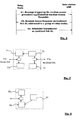
- FIG. 7 shows an embodiment of a relay node according to the present invention.
- the relay node comprises an interface 71 b towards the backhaul link to communicate with base stations, and an interface 71 a towards the access link to communicate with user equipments.
- the relay node comprises a module 72 for detecting the need for triggering a random access while in connected mode on the access link. Events monitored by module 72 are for example:
- Module 72 is further adapted to generate a random access trigger message to be sent on the backhaul link.
- This trigger message is preferably containing a dedicated random access preamble and sent on the RACH or on a dedicated resource previously allocated to the relay node for communication on the backhaul link.
- Module 72 is further adapted to generate a random access trigger message to be sent on the backhaul link.
- This trigger message is preferably containing a random access preamble out of a pre-assigned group of random access preambles and sent on the RACH or on a dedicated resource previously allocated to the relay node for communication on the backhaul link.
- Module 72 is connected to module 74 adapted to control the access interface.
- Module 74 is only impacted by the present invention when module 72 uses the RACH for transmitting the trigger message. In this case module 74 should configure the access link so as not to get any activity on the access link while transmitting the random access trigger message on the backhaul interface.
- Relay node further comprises a module 73 for receiving message of the random access procedure on resources configured for the backhaul link before the random access procedure has started.
- the configured resource may have been controlled by the base station or alternatively may have been determined centrally at an operation and maintenance center and then preferably communicated to the relay node.
- the random access response of the random access procedure is received by module 73 either as part of a MBSFN sub frame or as a message addressed to the relay node or a group of relay nodes as previously described in connection with the detailed description of 3 embodiments of the method for performing the random access procedure at a relay node.
- Relay node further comprises a data storage module 75 for storing data received on the active access link from user equipment and keep them for the duration of the random access procedure on the backhaul link.
- Data storage module is adapted to forward the stored data upon completion of the random access procedure on the backhaul link.
- FIG. 8 shows an embodiment of a base station according to the present invention.
- the base station comprises a module 81 for configuring resources for the backhaul link between the base station and the relay node. This configuration of resources is primarily used when the relay node is in connected mode on the backhaul link and on its access link. Further the base station comprises a module 82 for receiving an indication that a relay node is starting a random access procedure while it is remaining in connected mode on its access link. This indication may be a message containing a dedicated random access preamble.
- this indication may be a trigger message is preferably containing a random access preamble out of a pre-assigned group of random access preambles and sent on the RACH or on a dedicated resource previously allocated to the relay node for communication on the backhaul link.
- the base station comprises a module 83 for sending messages of said random access procedure on resources configured by module 81 for the backhaul link of the relay node. Doing this, the base station ensures that the random access procedure messages will not be colliding with the messages exchanged on the access link of the relay node.
- Module 83 sends preferably a random access response either as part of the MBSFN sub frame or on a relay node specific allocated resource on the backhaul link specifically addressed to the relay node or addressed to a group of relay nodes as already described in combination with the method for performing random access procedure at a relay node.
Claims (12)
- Verfahren zur Durchführung einer Direktzugriffsprozedur durch einen im Inband-Weiterleitungsmodus betriebenen Relaisknoten (RN) in einem Drahtlos- oder Funkkommunikationsnetzwerk mit mindestens einer für die Kommunikation, über eine Backhaul-Verbindung (Un), mit mindestens einem Relaisknoten (RN) ausgelegten Basisstation (eNB), wobei der besagte Relaisknoten (RN) für die Kommunikation, über eine Zugangsverbindung (Uu), mit mindestens einem Benutzerendgerät (UE) ausgelegt ist, wobei das besagte Verfahren die folgenden Schritte umfasst:- Konfigurieren von Ressourcen für die besagte Backhaul-Verbindung (Un) und für die an dem besagten Relaisknoten zeitlich zu multiplexende Zugangsverbindung,wobei das besagte Verfahren dadurch gekennzeichnet ist, dass es weiterhin die folgenden Schritte umfasst:- Senden von Nachrichten (32) der besagten Direktzugriffsprozedur auf Ressourcen, die für die besagte Backhaul-Verbindung (Un) konfiguriert sind,- Fortsetzen der Kommunikation auf der besagten Zugangsverbindung (Uu) zwischen dem besagten Relaisknoten (RN) und dem besagten Benutzerendgerät (RE) während der Durchführung der besagten Direktzugriffsprozedur auf der besagten Backhaul-Verbindung (Un).
- Verfahren nach Anspruch 1, wobei eine Direktzugriffsantwort (32) der besagten Direktzugriffsprozedur in einem reservierten MBSFN-Teilrahmen (421) auf der besagten Backhaul-Verbindung (Un) von der besagten Basisstation (eNB) an den besagten Relaisknoten (RN) gesendet wird, wobei der besagte Relaisknoten (RN) Ressourcen auf der besagten Zugangsverbindung (Uu), die mit dem besagten reservierten MBSFN-Teilrahmen (421) zeitlich gemultiplext werden sollen, konfiguriert.
- Verfahren nach Anspruch 1, wobei eine Direktzugriffsantwort (52) der besagten Direktzugriffsprozedur nur an den besagten Relaisknoten (RN), der die besagte Direktzugriffsprozedur auf Ressourcen, die während des vorherigen Schritts durch die besagte Basisstation (eNB) für die besagte Backhaul-Verbindung (Un) des besagten Relaisknotens konfiguriert worden sind, gestartet hat, gesendet wird.
- Verfahren nach Anspruch 1, wobei eine Direktzugriffsantwort (62) der besagten Direktzugriffsprozedur an eine Gruppe von Relaisknoten, einschließlich des besagten Relaisknotens (RN), der die besagte Direktzugriffsprozedur gestartet hat, auf einer in einem vorherigen Schritt von der besagten Basisstation (eNB) für die besagte Backhaul-Verbindung der besagten Gruppe von Relaisknoten konfigurierten Ressource gesendet wird.
- Verfahren nach Anspruch 1, weiterhin die folgenden Schritte umfassend:- Zuweisen, an den besagten Relaisknoten (RN), einer Direktzugriffskanalressource mit einer Direktzugriffspräambel, welche den besagten Relaisknoten eindeutig identifiziert;- Senden der besagten Direktzugriffspräambel, welche den besagten Relaisknoten, der die besagte Direktzugriffsprozedur startet, identifiziert, auf einem Direktzugriffskanal an die besagte Basisstation (eNB); und- Durchführen einer Identifikation des besagten Relaisknotens (RN) an der besagten Basisstation (eNB).
- Verfahren nach Anspruch 5, wobei eine Gruppe von Relaisknoten anhand einer Direktzugriffspräambel oder einer Gruppe von Direktzugriffspräambeln identifiziert wird.
- Verfahren nach Anspruch 1, wobei die besagte Konfiguration von Ressourcen für die besagte Backhaul-Verbindung durch die besagte Basisstation (eNB) durchgeführt wird.
- Verfahren nach Anspruch 1, wobei die besagte Konfiguration von Ressourcen für die besagte Backhaul-Verbindung durch ein Betriebs- und Wartungszentrum durchgeführt wird.
- Relaisknoten (RN) für die Verwendung in einem Drahtlos- oder Funkkommunikationsnetzwerk, wobei der besagte Relaisknoten (RN) für die Kommunikation über eine Backhaul-Verbindung (Un) zu mindestens einer Basisstation (eNB) und über eine Zugangsverbindung (Uu) zu mindestens einem Benutzerendgerät (UE) ausgelegt ist, wobei der besagte Relaisknoten (RN) im Inband-Weiterleitungsmodus betrieben wird, wobei der besagte Relaisknoten dadurch gekennzeichnet ist, dass er umfasst:- Mittel zum Starten einer Direktzugriffsprozedur, während er sich im Zustand einer Kommunikationsverbindung auf der Zugangsverbindung (Uu) befindet;- Mittel zum Empfangen von Nachrichten der besagten Direktzugriffsprozedur auf Ressourcen, die für die besagte Backhaul-Verbindung (Un) konfiguriert sind, während die Kommunikationsverbindung auf der besagten Zugangsverbindung (Uu) fortgesetzt wird.
- Relaisknoten (RN) nach Anspruch 9, wobei- die besagten Mittel zum Starten einer Direktzugriffsprozedur im Zustand einer Kommunikationsverbindung auf der besagten Zugangsverbindung Mittel zum Senden einer Direktzugriffspräambel in einem Direktzugriffskanal auf einer Backhaul-Verbindung, während die Kommunikationsverbindung auf der besagten Zugangsverbindung fortgesetzt wird, umfassen.
- Relaisknoten (RN) nach Anspruch 9, wobei der besagte Relaisknoten die Zugangsverbindung für das besagte an den Relaisknoten angeschlossene Benutzerendgerät steuert.
- Relaisknoten (RN) nach Anspruch 9, weiterhin umfassend Mittel zum Speichern von von dem besagten Benutzerendgerät (UE) über die Zugangsverbindung (Uu) empfangenen Daten, während der besagte Relaisknoten (RN) die Direktzugriffsprozedur durchführt, und Mittel zum Senden der besagten gespeicherten Daten nach Beenden der besagten Direktzugriffsprozedur über die besagte Backhaul-Verbindung (Un).
Priority Applications (5)
| Application Number | Priority Date | Filing Date | Title |
|---|---|---|---|
| EP10305151A EP2362708B1 (de) | 2010-02-15 | 2010-02-15 | Verfahren zur Durchführung einer Direktzugriffsprozedur durch einen Relaisknoten in einem Drahtlos- oder Funkkommunikationsnetzwerk, zugehöriger Relaisknoten |
| PCT/EP2011/051211 WO2011098362A1 (en) | 2010-02-15 | 2011-01-28 | Method for performing a random access procedure by a relay node in a wireless or radio communication network, corresponding relay node and base station |
| US13/579,114 US20120307717A1 (en) | 2010-02-15 | 2011-01-28 | Method for performing a random access procedure by a relay node in a wireless or radio communication network, corresponding relay node and base station |
| CN2011800052354A CN102696275A (zh) | 2010-02-15 | 2011-01-28 | 无线或无线电通信网络中由中继节点执行随机接入过程的方法、对应的中继节点和基站 |
| TW100103978A TW201204147A (en) | 2010-02-15 | 2011-02-01 | Method for performing a random access procedure by a relay node in a wireless or radio communication network, corresponding relay node and base station |
Applications Claiming Priority (1)
| Application Number | Priority Date | Filing Date | Title |
|---|---|---|---|
| EP10305151A EP2362708B1 (de) | 2010-02-15 | 2010-02-15 | Verfahren zur Durchführung einer Direktzugriffsprozedur durch einen Relaisknoten in einem Drahtlos- oder Funkkommunikationsnetzwerk, zugehöriger Relaisknoten |
Publications (2)
| Publication Number | Publication Date |
|---|---|
| EP2362708A1 EP2362708A1 (de) | 2011-08-31 |
| EP2362708B1 true EP2362708B1 (de) | 2012-09-19 |
Family
ID=42313727
Family Applications (1)
| Application Number | Title | Priority Date | Filing Date |
|---|---|---|---|
| EP10305151A Not-in-force EP2362708B1 (de) | 2010-02-15 | 2010-02-15 | Verfahren zur Durchführung einer Direktzugriffsprozedur durch einen Relaisknoten in einem Drahtlos- oder Funkkommunikationsnetzwerk, zugehöriger Relaisknoten |
Country Status (5)
| Country | Link |
|---|---|
| US (1) | US20120307717A1 (de) |
| EP (1) | EP2362708B1 (de) |
| CN (1) | CN102696275A (de) |
| TW (1) | TW201204147A (de) |
| WO (1) | WO2011098362A1 (de) |
Families Citing this family (23)
| Publication number | Priority date | Publication date | Assignee | Title |
|---|---|---|---|---|
| CN102083228B (zh) * | 2010-02-11 | 2015-05-20 | 电信科学技术研究院 | 一种中继系统的随机接入方法和设备 |
| JP4990386B2 (ja) * | 2010-07-08 | 2012-08-01 | 株式会社エヌ・ティ・ティ・ドコモ | 移動通信方法、無線基地局及びリレーノード |
| CN102202415B (zh) * | 2011-05-18 | 2019-01-22 | 中兴通讯股份有限公司 | 一种物理随机接入信道的传输方法和系统 |
| KR102191871B1 (ko) * | 2012-12-30 | 2020-12-16 | 엘지전자 주식회사 | 다중 셀 무선 통신 시스템에서 무선 자원 정보 공유 방법 및 이를 위한 장치 |
| WO2014173465A1 (en) * | 2013-04-26 | 2014-10-30 | Telefonaktiebolaget L M Ericsson (Publ) | Configuration of communications link to backhaul hub according to predicted backhaul capacity need based on control signalling received prior to user data |
| US10506562B2 (en) | 2013-04-26 | 2019-12-10 | Telefonaktiebolaget Lm Ericsson (Publ) | Communications link configuration |
| CN104184548B (zh) * | 2014-04-17 | 2019-02-15 | 中兴通讯股份有限公司 | 随机接入序列传输方法和装置 |
| FR3022096B1 (fr) * | 2014-06-06 | 2018-11-02 | Airbus Ds Sas | Basculement progressif de bande de frequences radio dans un noeud relais |
| CN107852366B (zh) * | 2015-06-17 | 2021-04-06 | 瑞典爱立信有限公司 | 减少网状网络中的延时的方法、中继节点和计算机可读存储介质 |
| US10499444B2 (en) * | 2015-09-11 | 2019-12-03 | Intel IP Corporation | Radio network access of wearable devices |
| WO2018139970A1 (en) * | 2017-01-24 | 2018-08-02 | Telefonaktiebolaget Lm Ericsson (Publ) | Control plane latency reduction in a wireless communications network |
| EP3639572B1 (de) * | 2017-05-12 | 2022-02-23 | Sony Group Corporation | Aufwecksignalübertragung auf relaisverbindungen |
| CN110121191B (zh) * | 2018-02-05 | 2022-12-06 | 成都华为技术有限公司 | 一种中继系统中资源配置的方法及装置 |
| EP3758418B1 (de) * | 2018-02-22 | 2023-09-20 | KDDI Corporation | Steuervorrichtung für ein zellulares kommunikationsnetzwerk, in dem die weitergeleitete kommunikation durchgeführt wird, basisstationsvorrichtung, endgerät, steuerverfahren dafür und programm |
| WO2020029163A1 (en) * | 2018-08-09 | 2020-02-13 | Zte Corporation | Methods, apparatus and systems for transmitting indication information |
| CN110831066B (zh) * | 2018-08-10 | 2022-08-30 | 中国移动通信有限公司研究院 | 资源处理方法和设备 |
| US11582676B2 (en) | 2018-09-07 | 2023-02-14 | Lg Electronics Inc. | Method for relay terminal to transmit and receive signals in wireless communication system, and device for same |
| US20210185723A1 (en) * | 2019-08-01 | 2021-06-17 | Qualcomm Incorporated | Access procedure configuration of a millimeter wave repeater |
| US11399395B2 (en) | 2019-09-18 | 2022-07-26 | Qualcomm Incorporated | Techniques for performing random access in full duplex wireless communications |
| US10986646B1 (en) | 2019-10-19 | 2021-04-20 | Skylo Technologies, Inc. | Scheduling virtual preambles for data source reporting |
| US20210298069A1 (en) * | 2020-03-23 | 2021-09-23 | Qualcomm Incorporated | Access procedure configuration of a millimeter wave repeater |
| CN112261627B (zh) * | 2020-10-20 | 2024-04-23 | 河南省四通锅炉有限公司 | 基于物联网的锅炉温度无线监测数据的高速传输方法及系统 |
| WO2024049333A1 (en) * | 2022-08-30 | 2024-03-07 | Telefonaktiebolaget Lm Ericsson (Publ) | A microwave communication node for detecting and mitigating interference |
Family Cites Families (12)
| Publication number | Priority date | Publication date | Assignee | Title |
|---|---|---|---|---|
| CN101146337B (zh) * | 2006-09-15 | 2011-04-20 | 华为技术有限公司 | 新接入节点随机接入的方法及其系统 |
| CN101448325B (zh) * | 2007-11-27 | 2012-11-21 | 电信科学技术研究院 | 一种随机接入过程中的处理方法和基站 |
| EP2306661B1 (de) * | 2008-07-30 | 2015-02-25 | LG Electronics Inc. | Relaisstation in einem funkkkommunikationssystem und betriebsverfahren für die relaisstation |
| KR101527978B1 (ko) * | 2008-08-06 | 2015-06-18 | 엘지전자 주식회사 | 기지국과 중계기 사이의 서브프레임을 사용하여 통신하는 방법 및 장치 |
| US8355734B2 (en) * | 2008-08-07 | 2013-01-15 | Apple Inc. | Wireless system |
| US8259637B2 (en) * | 2009-01-06 | 2012-09-04 | Texas Instruments Incorporated | In-band backhaul for wireless relays in wireless networks |
| US8305965B2 (en) * | 2009-01-06 | 2012-11-06 | Texas Instruments Incorporated | Protocol stack and scheduler for L3 relay |
| KR101539777B1 (ko) * | 2009-01-14 | 2015-08-07 | 엘지전자 주식회사 | 무선통신 시스템에서 백홀 신호 전송 방법 |
| CN102318228B (zh) * | 2009-02-11 | 2015-11-25 | Lg电子株式会社 | 用于传送上行链路信号和反馈信息的方法以及使用该方法的中继装置 |
| WO2010107357A1 (en) * | 2009-03-20 | 2010-09-23 | Telefonaktiebolaget L M Ericsson (Publ) | Radio bearer identification for self backhauling and relaying in lte advanced |
| CN101883437B (zh) * | 2009-05-05 | 2014-12-10 | 中兴通讯股份有限公司 | 随机接入方法以及基站 |
| US8953476B2 (en) * | 2009-11-03 | 2015-02-10 | Nokia Siemens Networks Oy | Method and apparatuses for data transfer within a relay enhanced telecommunication network |
-
2010
- 2010-02-15 EP EP10305151A patent/EP2362708B1/de not_active Not-in-force
-
2011
- 2011-01-28 US US13/579,114 patent/US20120307717A1/en not_active Abandoned
- 2011-01-28 CN CN2011800052354A patent/CN102696275A/zh active Pending
- 2011-01-28 WO PCT/EP2011/051211 patent/WO2011098362A1/en active Application Filing
- 2011-02-01 TW TW100103978A patent/TW201204147A/zh unknown
Also Published As
| Publication number | Publication date |
|---|---|
| TW201204147A (en) | 2012-01-16 |
| CN102696275A (zh) | 2012-09-26 |
| US20120307717A1 (en) | 2012-12-06 |
| EP2362708A1 (de) | 2011-08-31 |
| WO2011098362A1 (en) | 2011-08-18 |
Similar Documents
| Publication | Publication Date | Title |
|---|---|---|
| EP2362708B1 (de) | Verfahren zur Durchführung einer Direktzugriffsprozedur durch einen Relaisknoten in einem Drahtlos- oder Funkkommunikationsnetzwerk, zugehöriger Relaisknoten | |
| US9155107B2 (en) | Random access method for relay nodes | |
| KR101742994B1 (ko) | 이동통신시스템에서 랜덤접속을 수행하는 방법 및 이를 위한 장치 | |
| KR101887062B1 (ko) | 무선 통신 시스템에서 신호 처리 방법 및 이를 위한 장치 | |
| EP2351401B1 (de) | Weiterleitung in einem kommunikationssystem | |
| US8750196B2 (en) | Method and device for relay node access | |
| EP2560452B1 (de) | Verfahren und vorrichtung für direktzugriff in einem relaissystem | |
| US9832768B2 (en) | Mobile communication method and radio base station | |
| JP7460642B2 (ja) | ランダムアクセス手順のための制御メカニズム | |
| CN102264098A (zh) | 一种缓冲区状态报告处理的方法和装置 | |
| KR20100094424A (ko) | 중계기의 신호 송수신 방법 및 그 방법을 이용하는 중계기 | |
| GB2493785A (en) | Uplink resource allocation for a wireless communications system comprising a base station, relay device and terminal device | |
| CN102158980B (zh) | 一种基于回程链路的随机接入方法、设备和系统 | |
| CN116034622A (zh) | 用户设备、基站和信息传输方法 | |
| US20130128803A1 (en) | Mobile communication method and relay node | |
| KR101227945B1 (ko) | 이동통신시스템 및 무선기지국 | |
| KR102327817B1 (ko) | 고속 열차 통신 네트워크의 신호 송수신 방법 및 장치 |
Legal Events
| Date | Code | Title | Description |
|---|---|---|---|
| PUAI | Public reference made under article 153(3) epc to a published international application that has entered the european phase |
Free format text: ORIGINAL CODE: 0009012 |
|
| AK | Designated contracting states |
Kind code of ref document: A1 Designated state(s): AT BE BG CH CY CZ DE DK EE ES FI FR GB GR HR HU IE IS IT LI LT LU LV MC MK MT NL NO PL PT RO SE SI SK SM TR |
|
| AX | Request for extension of the european patent |
Extension state: AL BA RS |
|
| RIN1 | Information on inventor provided before grant (corrected) |
Inventor name: PALAT, SUDEEP Inventor name: WORRAL, CHANDRIKA Inventor name: LIM, SEAU SIAN |
|
| RAP1 | Party data changed (applicant data changed or rights of an application transferred) |
Owner name: ALCATEL LUCENT |
|
| 17P | Request for examination filed |
Effective date: 20120228 |
|
| GRAP | Despatch of communication of intention to grant a patent |
Free format text: ORIGINAL CODE: EPIDOSNIGR1 |
|
| GRAS | Grant fee paid |
Free format text: ORIGINAL CODE: EPIDOSNIGR3 |
|
| GRAA | (expected) grant |
Free format text: ORIGINAL CODE: 0009210 |
|
| AK | Designated contracting states |
Kind code of ref document: B1 Designated state(s): AT BE BG CH CY CZ DE DK EE ES FI FR GB GR HR HU IE IS IT LI LT LU LV MC MK MT NL NO PL PT RO SE SI SK SM TR |
|
| REG | Reference to a national code |
Ref country code: GB Ref legal event code: FG4D |
|
| REG | Reference to a national code |
Ref country code: CH Ref legal event code: EP |
|
| REG | Reference to a national code |
Ref country code: IE Ref legal event code: FG4D |
|
| REG | Reference to a national code |
Ref country code: AT Ref legal event code: REF Ref document number: 576543 Country of ref document: AT Kind code of ref document: T Effective date: 20121015 |
|
| REG | Reference to a national code |
Ref country code: DE Ref legal event code: R096 Ref document number: 602010002910 Country of ref document: DE Effective date: 20121115 |
|
| PG25 | Lapsed in a contracting state [announced via postgrant information from national office to epo] |
Ref country code: HR Free format text: LAPSE BECAUSE OF FAILURE TO SUBMIT A TRANSLATION OF THE DESCRIPTION OR TO PAY THE FEE WITHIN THE PRESCRIBED TIME-LIMIT Effective date: 20120919 Ref country code: NO Free format text: LAPSE BECAUSE OF FAILURE TO SUBMIT A TRANSLATION OF THE DESCRIPTION OR TO PAY THE FEE WITHIN THE PRESCRIBED TIME-LIMIT Effective date: 20121219 Ref country code: FI Free format text: LAPSE BECAUSE OF FAILURE TO SUBMIT A TRANSLATION OF THE DESCRIPTION OR TO PAY THE FEE WITHIN THE PRESCRIBED TIME-LIMIT Effective date: 20120919 Ref country code: LT Free format text: LAPSE BECAUSE OF FAILURE TO SUBMIT A TRANSLATION OF THE DESCRIPTION OR TO PAY THE FEE WITHIN THE PRESCRIBED TIME-LIMIT Effective date: 20120919 |
|
| REG | Reference to a national code |
Ref country code: NL Ref legal event code: VDEP Effective date: 20120919 |
|
| REG | Reference to a national code |
Ref country code: AT Ref legal event code: MK05 Ref document number: 576543 Country of ref document: AT Kind code of ref document: T Effective date: 20120919 |
|
| REG | Reference to a national code |
Ref country code: LT Ref legal event code: MG4D Effective date: 20120919 |
|
| PG25 | Lapsed in a contracting state [announced via postgrant information from national office to epo] |
Ref country code: SI Free format text: LAPSE BECAUSE OF FAILURE TO SUBMIT A TRANSLATION OF THE DESCRIPTION OR TO PAY THE FEE WITHIN THE PRESCRIBED TIME-LIMIT Effective date: 20120919 Ref country code: SE Free format text: LAPSE BECAUSE OF FAILURE TO SUBMIT A TRANSLATION OF THE DESCRIPTION OR TO PAY THE FEE WITHIN THE PRESCRIBED TIME-LIMIT Effective date: 20120919 Ref country code: GR Free format text: LAPSE BECAUSE OF FAILURE TO SUBMIT A TRANSLATION OF THE DESCRIPTION OR TO PAY THE FEE WITHIN THE PRESCRIBED TIME-LIMIT Effective date: 20121220 Ref country code: LV Free format text: LAPSE BECAUSE OF FAILURE TO SUBMIT A TRANSLATION OF THE DESCRIPTION OR TO PAY THE FEE WITHIN THE PRESCRIBED TIME-LIMIT Effective date: 20120919 |
|
| PG25 | Lapsed in a contracting state [announced via postgrant information from national office to epo] |
Ref country code: EE Free format text: LAPSE BECAUSE OF FAILURE TO SUBMIT A TRANSLATION OF THE DESCRIPTION OR TO PAY THE FEE WITHIN THE PRESCRIBED TIME-LIMIT Effective date: 20120919 Ref country code: NL Free format text: LAPSE BECAUSE OF FAILURE TO SUBMIT A TRANSLATION OF THE DESCRIPTION OR TO PAY THE FEE WITHIN THE PRESCRIBED TIME-LIMIT Effective date: 20120919 Ref country code: CZ Free format text: LAPSE BECAUSE OF FAILURE TO SUBMIT A TRANSLATION OF THE DESCRIPTION OR TO PAY THE FEE WITHIN THE PRESCRIBED TIME-LIMIT Effective date: 20120919 Ref country code: RO Free format text: LAPSE BECAUSE OF FAILURE TO SUBMIT A TRANSLATION OF THE DESCRIPTION OR TO PAY THE FEE WITHIN THE PRESCRIBED TIME-LIMIT Effective date: 20120919 Ref country code: BE Free format text: LAPSE BECAUSE OF FAILURE TO SUBMIT A TRANSLATION OF THE DESCRIPTION OR TO PAY THE FEE WITHIN THE PRESCRIBED TIME-LIMIT Effective date: 20120919 Ref country code: IS Free format text: LAPSE BECAUSE OF FAILURE TO SUBMIT A TRANSLATION OF THE DESCRIPTION OR TO PAY THE FEE WITHIN THE PRESCRIBED TIME-LIMIT Effective date: 20130119 |
|
| PG25 | Lapsed in a contracting state [announced via postgrant information from national office to epo] |
Ref country code: PL Free format text: LAPSE BECAUSE OF FAILURE TO SUBMIT A TRANSLATION OF THE DESCRIPTION OR TO PAY THE FEE WITHIN THE PRESCRIBED TIME-LIMIT Effective date: 20120919 Ref country code: SK Free format text: LAPSE BECAUSE OF FAILURE TO SUBMIT A TRANSLATION OF THE DESCRIPTION OR TO PAY THE FEE WITHIN THE PRESCRIBED TIME-LIMIT Effective date: 20120919 Ref country code: PT Free format text: LAPSE BECAUSE OF FAILURE TO SUBMIT A TRANSLATION OF THE DESCRIPTION OR TO PAY THE FEE WITHIN THE PRESCRIBED TIME-LIMIT Effective date: 20130121 |
|
| PG25 | Lapsed in a contracting state [announced via postgrant information from national office to epo] |
Ref country code: AT Free format text: LAPSE BECAUSE OF FAILURE TO SUBMIT A TRANSLATION OF THE DESCRIPTION OR TO PAY THE FEE WITHIN THE PRESCRIBED TIME-LIMIT Effective date: 20120919 |
|
| PLBE | No opposition filed within time limit |
Free format text: ORIGINAL CODE: 0009261 |
|
| STAA | Information on the status of an ep patent application or granted ep patent |
Free format text: STATUS: NO OPPOSITION FILED WITHIN TIME LIMIT |
|
| PG25 | Lapsed in a contracting state [announced via postgrant information from national office to epo] |
Ref country code: BG Free format text: LAPSE BECAUSE OF FAILURE TO SUBMIT A TRANSLATION OF THE DESCRIPTION OR TO PAY THE FEE WITHIN THE PRESCRIBED TIME-LIMIT Effective date: 20121219 Ref country code: DK Free format text: LAPSE BECAUSE OF FAILURE TO SUBMIT A TRANSLATION OF THE DESCRIPTION OR TO PAY THE FEE WITHIN THE PRESCRIBED TIME-LIMIT Effective date: 20120919 |
|
| 26N | No opposition filed |
Effective date: 20130620 |
|
| PG25 | Lapsed in a contracting state [announced via postgrant information from national office to epo] |
Ref country code: IT Free format text: LAPSE BECAUSE OF FAILURE TO SUBMIT A TRANSLATION OF THE DESCRIPTION OR TO PAY THE FEE WITHIN THE PRESCRIBED TIME-LIMIT Effective date: 20120919 |
|
| PG25 | Lapsed in a contracting state [announced via postgrant information from national office to epo] |
Ref country code: MC Free format text: LAPSE BECAUSE OF NON-PAYMENT OF DUE FEES Effective date: 20130228 |
|
| REG | Reference to a national code |
Ref country code: DE Ref legal event code: R097 Ref document number: 602010002910 Country of ref document: DE Effective date: 20130620 |
|
| PG25 | Lapsed in a contracting state [announced via postgrant information from national office to epo] |
Ref country code: ES Free format text: LAPSE BECAUSE OF FAILURE TO SUBMIT A TRANSLATION OF THE DESCRIPTION OR TO PAY THE FEE WITHIN THE PRESCRIBED TIME-LIMIT Effective date: 20121230 |
|
| REG | Reference to a national code |
Ref country code: FR Ref legal event code: GC Effective date: 20131018 |
|
| PG25 | Lapsed in a contracting state [announced via postgrant information from national office to epo] |
Ref country code: CY Free format text: LAPSE BECAUSE OF FAILURE TO SUBMIT A TRANSLATION OF THE DESCRIPTION OR TO PAY THE FEE WITHIN THE PRESCRIBED TIME-LIMIT Effective date: 20120919 |
|
| REG | Reference to a national code |
Ref country code: IE Ref legal event code: MM4A |
|
| PG25 | Lapsed in a contracting state [announced via postgrant information from national office to epo] |
Ref country code: IE Free format text: LAPSE BECAUSE OF NON-PAYMENT OF DUE FEES Effective date: 20130215 |
|
| PG25 | Lapsed in a contracting state [announced via postgrant information from national office to epo] |
Ref country code: MT Free format text: LAPSE BECAUSE OF FAILURE TO SUBMIT A TRANSLATION OF THE DESCRIPTION OR TO PAY THE FEE WITHIN THE PRESCRIBED TIME-LIMIT Effective date: 20120919 |
|
| REG | Reference to a national code |
Ref country code: CH Ref legal event code: PCOW Free format text: NEW ADDRESS: 148/152 ROUTE DE LA REINE, 92100 BOULOGNE-BILLANCOURT (FR) |
|
| REG | Reference to a national code |
Ref country code: CH Ref legal event code: PL |
|
| PG25 | Lapsed in a contracting state [announced via postgrant information from national office to epo] |
Ref country code: CH Free format text: LAPSE BECAUSE OF NON-PAYMENT OF DUE FEES Effective date: 20140228 Ref country code: LI Free format text: LAPSE BECAUSE OF NON-PAYMENT OF DUE FEES Effective date: 20140228 |
|
| REG | Reference to a national code |
Ref country code: FR Ref legal event code: PLFP Year of fee payment: 6 |
|
| PG25 | Lapsed in a contracting state [announced via postgrant information from national office to epo] |
Ref country code: SM Free format text: LAPSE BECAUSE OF FAILURE TO SUBMIT A TRANSLATION OF THE DESCRIPTION OR TO PAY THE FEE WITHIN THE PRESCRIBED TIME-LIMIT Effective date: 20120919 |
|
| PG25 | Lapsed in a contracting state [announced via postgrant information from national office to epo] |
Ref country code: TR Free format text: LAPSE BECAUSE OF FAILURE TO SUBMIT A TRANSLATION OF THE DESCRIPTION OR TO PAY THE FEE WITHIN THE PRESCRIBED TIME-LIMIT Effective date: 20120919 |
|
| PG25 | Lapsed in a contracting state [announced via postgrant information from national office to epo] |
Ref country code: MK Free format text: LAPSE BECAUSE OF FAILURE TO SUBMIT A TRANSLATION OF THE DESCRIPTION OR TO PAY THE FEE WITHIN THE PRESCRIBED TIME-LIMIT Effective date: 20120919 Ref country code: LU Free format text: LAPSE BECAUSE OF NON-PAYMENT OF DUE FEES Effective date: 20130215 Ref country code: HU Free format text: LAPSE BECAUSE OF FAILURE TO SUBMIT A TRANSLATION OF THE DESCRIPTION OR TO PAY THE FEE WITHIN THE PRESCRIBED TIME-LIMIT; INVALID AB INITIO Effective date: 20100215 |
|
| REG | Reference to a national code |
Ref country code: FR Ref legal event code: PLFP Year of fee payment: 7 |
|
| REG | Reference to a national code |
Ref country code: FR Ref legal event code: PLFP Year of fee payment: 8 |
|
| REG | Reference to a national code |
Ref country code: FR Ref legal event code: PLFP Year of fee payment: 9 |
|
| PGFP | Annual fee paid to national office [announced via postgrant information from national office to epo] |
Ref country code: FR Payment date: 20190111 Year of fee payment: 10 Ref country code: GB Payment date: 20190213 Year of fee payment: 10 Ref country code: DE Payment date: 20190205 Year of fee payment: 10 |
|
| REG | Reference to a national code |
Ref country code: DE Ref legal event code: R119 Ref document number: 602010002910 Country of ref document: DE |
|
| GBPC | Gb: european patent ceased through non-payment of renewal fee |
Effective date: 20200215 |
|
| PG25 | Lapsed in a contracting state [announced via postgrant information from national office to epo] |
Ref country code: DE Free format text: LAPSE BECAUSE OF NON-PAYMENT OF DUE FEES Effective date: 20200901 Ref country code: GB Free format text: LAPSE BECAUSE OF NON-PAYMENT OF DUE FEES Effective date: 20200215 Ref country code: FR Free format text: LAPSE BECAUSE OF NON-PAYMENT OF DUE FEES Effective date: 20200229 |