EP2362534A2 - Systems and Methods for Controlling Electronic Circuitry with Separated Controllers - Google Patents
Systems and Methods for Controlling Electronic Circuitry with Separated Controllers Download PDFInfo
- Publication number
- EP2362534A2 EP2362534A2 EP11155331A EP11155331A EP2362534A2 EP 2362534 A2 EP2362534 A2 EP 2362534A2 EP 11155331 A EP11155331 A EP 11155331A EP 11155331 A EP11155331 A EP 11155331A EP 2362534 A2 EP2362534 A2 EP 2362534A2
- Authority
- EP
- European Patent Office
- Prior art keywords
- controller
- electronic circuitry
- power electronic
- hssl
- circuitry module
- Prior art date
- Legal status (The legal status is an assumption and is not a legal conclusion. Google has not performed a legal analysis and makes no representation as to the accuracy of the status listed.)
- Granted
Links
Images




Classifications
-
- G—PHYSICS
- G05—CONTROLLING; REGULATING
- G05B—CONTROL OR REGULATING SYSTEMS IN GENERAL; FUNCTIONAL ELEMENTS OF SUCH SYSTEMS; MONITORING OR TESTING ARRANGEMENTS FOR SUCH SYSTEMS OR ELEMENTS
- G05B9/00—Safety arrangements
- G05B9/02—Safety arrangements electric
- G05B9/03—Safety arrangements electric with multiple-channel loop, i.e. redundant control systems
-
- G—PHYSICS
- G05—CONTROLLING; REGULATING
- G05B—CONTROL OR REGULATING SYSTEMS IN GENERAL; FUNCTIONAL ELEMENTS OF SUCH SYSTEMS; MONITORING OR TESTING ARRANGEMENTS FOR SUCH SYSTEMS OR ELEMENTS
- G05B2219/00—Program-control systems
- G05B2219/20—Pc systems
- G05B2219/24—Pc safety
- G05B2219/24192—Configurable redundancy
-
- H—ELECTRICITY
- H02—GENERATION; CONVERSION OR DISTRIBUTION OF ELECTRIC POWER
- H02M—APPARATUS FOR CONVERSION BETWEEN AC AND AC, BETWEEN AC AND DC, OR BETWEEN DC AND DC, AND FOR USE WITH MAINS OR SIMILAR POWER SUPPLY SYSTEMS; CONVERSION OF DC OR AC INPUT POWER INTO SURGE OUTPUT POWER; CONTROL OR REGULATION THEREOF
- H02M1/00—Details of apparatus for conversion
- H02M1/0003—Details of control, feedback or regulation circuits
- H02M1/0012—Control circuits using digital or numerical techniques
Definitions
- Embodiments of the invention relate generally to electronic controllers, and more specifically relate to systems and methods for controlling electronic circuitry with separated controllers.
- controllers are typically closely coupled with the corresponding power converter circuitry due to the number of input/output (I/O) connections necessary for system control and protection.
- I/O input/output
- This close coupling can restrict the ability to reuse components independently in various system architectures. This in turn reduces usage volume of the components and constrains incremental and major enhancements to individual power conversion components.
- the close coupling also creates electrical issues, such as conduction of electrical noise (EMI), ambient noise issues, and increases the potential for hazardous events, such as excessive heat, arc flashing, and fire from the converter circuitry to the controller.
- EMI electrical noise
- a system for controlling electronic circuitry can include at least a first controller and a second controller and at least one power electronic circuitry module.
- the first controller can be in electrical communication with the power electronic circuitry module via a first high-speed serial link (HSSL).
- the second controller can be in electrical communication with the power electronic circuitry module via a second HSSL.
- HSSL high-speed serial link
- a method for controlling electronic circuitry can include providing at least a first controller and a second controller and providing at least one power electronic circuitry module in electrical communication with the first controller and the second controller via a first high-speed serial link and a second HSSL, respectively.
- the method can further include transmitting serial communications between the first controller and the power electronic circuitry module via the first HSSL and transmitting serial communications between the second controller and the power electronic circuitry module via the second HSSL.
- a system for controlling electronic circuitry can include a controller in operable electrical communication with a exciter electronic circuitry via a high-speed serial link.
- Embodiments of the systems and methods described herein provide a flexible control architecture for use in power conversion systems.
- Example power conversion systems may include, but are not limited to, generator exciters, static starters, or motor drives. Flexibility is achieved, in part, by separating the controller component(s) from the power conversion electronics and circuitry component(s). Separation is accomplished, in part, by providing one or more high-speed serial links (HSSL) for communicating between the controller component(s) and the power conversion electronics and circuitry component(s).
- HSSL high-speed serial links
- the HSSL(s) and respective interfaces permit simplex control of one or more power electronic circuitry modules by a single controller, as well as redundant and/or distributed control by multiple controllers.
- HSSL protocol allows implementing a standard processor having a normalized or standardized I/O interface across varied product applications, installations, and/or system architectures. Separable control architecture using HSSL communication also simplifies the ability to retrofit power electronic circuitry modules with new controllers, as well as the ability to make architecture enhancements independently or in a phased manner. Moreover, HSSL protocol provide simplified communications hardware having fewer components and, therefore, reduce costs of implementation and modification.
- HSSL communication links between controllers and power electronic circuitry modules allows physical separation therebetween at distances much greater than previous parallel communications interfaces. Separation increases safety for operators and convenience associated with control rooms by eliminating the need to locate controllers in the immediate proximity of the power conversion electronics being controlled.
- FIG. 1 illustrates a block diagram of an example system 100 (e.g., a power plant or other environment) in which systems for controlling electronic circuitry according to the various embodiments described herein may be implemented.
- the system 100 represents a simplified power plant having a prime mover source 110 (e.g., hydro, wind, gas, steam, nuclear, etc.) providing mechanical energy to rotating machinery 120 (e.g., a generator, etc.), which is controlled by an exciter 130 (e.g., a field exciter, etc.).
- FIG. 1 shows that the exciter 130 includes one or more controllers 140 and one or more power electronic circuitry modules 150, such as are known for controlling power to the field of the rotating machinery 120.
- the controller(s) 140 are in communication with the power electronic circuitry modules 150 via one or more HSSLs 160 and respective interfaces that are programmed to communicate via HSSL protocol (referred to generally and interchangeably herein as "HSSL” and “HSSL interface”), which permits increased separation between the power electronic circuitry module 150 and the controller 140.
- HSSL HSSL protocol
- HSSL interface HSSL protocol
- a HSSL and associated interface may be implemented by each controller 140 being programmed to convert parallel communications to serial communications via a HSSL protocol, which permits communicating serially to one or more power electronic circuitry modules 150 (or other components) using a HSSL.
- the controller 140 may include a microcontroller or a field-programmable gate array (FPGA) programmed accordingly.
- each power electronic circuitry module 150 is programmed (e.g., via a microcontroller or a FPGA, etc.) to convert the HSSL serial communications to parallel communications for further operations by the power electronic circuitry module 150.
- HSSL 160 In contrast to the HSSL 160 described herein, conventional exciters (or other electronic circuitry control components) communicated via parallel communication interfaces, which requires a large number of communication lines and ports in close proximity between the components.
- the HSSL 160 protocol allows high-speed bi-directional data communication that is real-time, deterministic, low jittering, and reconfigurable to occur over greater distances.
- a HSSL 160 and respective interfaces can also be configured to implement forward error correction and cyclic redundancy check (CRC) error detection (or other hash function detection means), which is beneficial in electrically noisy (e.g., high EMI) environments.
- CRC cyclic redundancy check
- a HSSL interface 160 can be implemented in either a field programmable gate array (FPGA), a microcontroller, or other programmable hardware, firmware, and/or software, and use Ethernet-type hardware for the communication link.
- Example communication links may include, but are not limited to, a twisted pair cable or a fiber optic pair cable.
- a HSSL 160 may use any other communication hardware, including, but not limited to, a controller-area network or CAN bus, an Inter-integrated Circuit (i2c) bus, a peripheral component interconnect (PCI) bus, and the like.
- a HSSL 160 and its associated interfaces are configured as a high-speed communication link that is fully duplexed and operable to communicate at speeds of up to 100 Mbits/second.
- a HSSL 160 may be operable to communicate at speeds less than, or greater than, 100 Mbits/second, such that the transmission speed is considered "high-speed" relative to other known transmission protocols.
- a HSSL 160 may be operable to communicate at speeds greater than 10 Mbits/second, for example, greater than 30 Mbits/second or greater than 50 Mbits/second. It is appreciated, however, that these transmission speeds are illustrative and not intended to be limiting, and that certain advancements not yet known may improve these transmission speeds.
- FIG. 2 shows one embodiment of controller and power electronic circuitry configured in a simplex configuration, in which a single controller 140 is in communication with a single power electronic circuitry module 150 via one or more HSSLs 160.
- the controller 140 is configured as a HSSL host and the power electronic circuitry module 150 is configured as the HSSL target for transmitting communications therebetween.
- FIG. 3 Another simplex configuration is illustrated in FIG. 3 , in which a single controller 140 is in communication with a first single power electronic circuitry module 150a and a second power electronic circuitry module 150b via a first HSSL 160a and a second HSSL 160b.
- the controller 140 is configured as the HSSL host and each of the first and second power electronic circuitry modules 150a, 150b are configured as targets.
- the first and second power electronic circuitry modules 150a, 150b may be operable to perform the same functions and configured to provide redundant circuitry or increased power rating, or may be operable to perform different functions (e.g., rectifiers, inverters, phase shifting, or other different control profiles for the exciter 130, etc.), according to various embodiments. It is also appreciated that, while FIG.
- FIG. 2 illustrates only two power electronic circuitry modules, in other embodiments, any number of power electronic circuitry modules may be in communication with, and controlled by, a controller via a HSSL.
- a single HSSL 160 is shown linking the controller 140 with each power electronic circuitry module 150, it is appreciated that, in other embodiments, multiple HSSLs 160 can be provided between a controller host and a single power electronic circuitry module target.
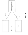
- FIGS. 4-6 illustrate multiple or complex configurations of controller and power electronic circuitry of an exciter 130.
- multiple controllers 140a, 140b are in communication with a single power electronic circuitry module 150 and in communication with each other via first, second, and third HSSLs 160a, 160b, 160c, respectively.
- a control system having this configuration allows redundant and/or distributed control of the single power electronic circuitry module 150.
- the first and second controllers 140a, 140b and the third HSSL 160c and respective interfaces are configured to receive and transmit operational status and operating data to allow for synchronization therebetween in redundant or distributed configurations.
- the power electronic circuitry module 150 and the HSSLs 160a, 160b and respective interfaces are likewise configured to determine which host controller 140a, 140b is active in a redundant configuration.
- redundant communications may be achieved by a target module (e.g., electronic circuitry module 150) initially "babbling" to announce its presence to a host controller 140 on an HSSL 160.
- the host controller 140 responds by establishing bi-directional communications and advancing the electronic circuitry module 150 through a configuration state and ultimately to a system running state.
- a target electronic circuitry module 150 is running with multiple host controllers 140 (e.g., host controllers 140a, 140b)
- determination of the active host controller can be achieved by various methods, such, but not limited to, executing known algorithms within the host controllers and/or the target circuitry, and/or via external selection devices, such as processor-based devices with selection logic executed thereby.
- FIG. 5 illustrates another redundant configuration for the controller and power electronic circuitry of the exciter 130, according to one embodiment.
- a first controller 140a is in communication with a first power electronic circuitry module 150a via a first HSSL 160a and respective interfaces
- a second controller 140b in communication with a second power electronic circuitry module 150b via a second HSSL 160b and respective interfaces
- the first and second controllers 140a, 140b are in communication with each other via a third HSSL 160c.
- the third HSSL 160c and associated interfaces permit each controller 140a, 140b to provide redundant control over either or both of the first and second power electronic circuitry modules 150a, 150b, which may themselves be configured for redundant operation with an exciter or for separate operation with an exciter, such as if each module provides a different function.
- a fourth HSSL 160d and a fifth HSSL 160e may optionally be provided, permitting direct communication between the first controller 140a and the second electronic circuitry module 150b via the fourth HSSL 160d, and between the second controller 140b and the first electronic circuitry module 150a via the fifth HSSL 160e, in a manner similar to that described with reference to FIG. 6 .
- the first controller 140a may be operative to provide primary control to both the first and second power electronic circuitry modules 150a, 150b, or to only control the first power electronic circuitry module 150a.
- the second controller 140a is operable to provide back-up control over the first and second power electronic circuitry modules 150a, 150b, or may provide control only to the second power electronic circuitry module 150b. It is appreciated that any other redundant and/or distributed configurations may be implemented in manners similar to that described with reference to FIG. 5 .
- two controllers and two power electronic circuitry modules are illustrated, in other embodiments there may be additional controllers and/or power electronic circuitry modules.
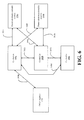
- FIG. 6 illustrates yet another redundant configuration for the controller and power electronic circuitry of the exciter 130, according to one embodiment.
- This example configuration has the capability of providing triple modular redundant (TMR) control of one or more power electronic circuitry modules.
- the system includes a first controller 140a, a second controller 140b, and a third controller 140c, as well as a first power electronic circuitry module 150a and a second power electronic circuitry module 150b (though, fewer or greater power electronic circuitry modules may be supplied).
- the first controller 140a and the second controller 140b may be in communication with the first power electronic circuitry module 150a and the second power electronic circuitry module 150b via a first HSSL 160a and a second HSSL 160b, respectively, in the same or similar manner as described with reference to FIG. 5 .
- each of the first, second, and third controllers 140a, 140b, 140c may be in communication with each other via third, fourth, and fifth HSSLs 160c, 160d, 160e.
- the first controller may be in communication with the second power electronic circuitry module 150b via a sixth HSSL 160f and the second controller may be in communication with the first power electronic circuitry module 150a via a seventh HSSL 160f.
- the redundant system configuration illustrated in the embodiment shown in FIG. 6 can provide TMR control over one or more of the power electronic circuitry modules.
- the third controller 140c is in communication with each of the other controllers 140a, 140b, but not with any of the power electronic circuitry modules 150a, 150b.
- the third controller 140c can be operative to serve as the "voter” to review operational status data and provide feedback as to whether one of the three controllers 140a, 140b, 140c is an outlier, which may indicate controller failure.
- TMR is shown in FIG. 6 , according to other embodiments, any other n-modular redundancy configuration may be implemented in a similar manner.
- the third controller 140c may also be in communication with one or more of the power electronic circuitry modules 150a, 150b.
- FIG. 6 also illustrates that one or more of the controllers 140a, 140b, 140c may be in communication with one or more other targets 170, which may include, but are not limited to, other control systems, customer I/O components, system I/O components, data logging components, other devices, and the like, via one or more additional HSSLs 160h.
- the other target(s) 170 may be used to provide input and/or additional control of the controller(a) 140a, 140b, 140c or any other system component, or can receive data from and/or be controlled by the controller(a) 140a, 140b, 140c, according to various embodiments.
- the other target 170 is shown as being in communication with the first controller 140a, it is appreciated that, in other embodiments, additional HSSLs can provide communication with any additional controller or other system component.
- FIG. 1 illustrates a power conversion system, and controllers and power electronic circuitry associated with an exciter for controlling a rotating machine
- FIG. 1 illustrates a power conversion system, and controllers and power electronic circuitry associated with an exciter for controlling a rotating machine
- similar system configurations have one or more controllers and one or more HSSLs may be used to control other electronic circuitry.
- Some examples of other circuitry may include, but are not limited to, electronic motor drives, wind turbine controls, or non-power-conversion applications where I/O may be distributed or separated from the controller(s).
- FIG. 7 provides a flowchart of an example method 700 for controlling electronic circuitry.
- one or more controllers are provided, such as the controllers 140 described above with reference to FIGS. 2-6 .
- one or more power electronic circuitry modules are provided, such as the power electronic circuitry modules 150 described above with reference to FIGS. 2-6 .
- the power electronic circuitry modules are in communication with one or more respective controllers (depending upon the configuration) via one or more HSSLs and respective interfaces.
- the controllers and the power electronic circuitry modules may be physically separated, which may be achieved due in part to the implementation of HSSL communication links.
- block 730 in which the controllers provide control commands to the power electronic circuitry modules via HSSL protocol over the HSSL communication links and associated interfaces.
- the control commands transmitted at block 730 may include configuration and/or status commands, such as to determine the active host and/or active target devices.
- the HSSL protocol used includes error correction and detection techniques, such as is known for high-speed serial communications. The method may end after block 730.
- various embodiments described herein provide one or more controllers in communication with one or more power electronic circuitry modules via one or more HSSLs. These embodiments provide the technical effects of permitting controllers to be physically separated from circuitry or other components being controlled. These embodiments achieve the additional technical effects of increasing safety, due to the physical separation of the controllers, improving interchangeability of controller and/or circuitry components, due in part to the modularity of the HSSL interfaces, and reducing operating and maintenance costs of control systems. Moreover, controlling an exciter and its electronic circuitry from a distance, and, optionally, using one or more redundant control configurations, improves system reliability and system flexibility.
Landscapes
- Physics & Mathematics (AREA)
- General Physics & Mathematics (AREA)
- Engineering & Computer Science (AREA)
- Automation & Control Theory (AREA)
- Inverter Devices (AREA)
- Information Transfer Systems (AREA)
Abstract
Description
- Embodiments of the invention relate generally to electronic controllers, and more specifically relate to systems and methods for controlling electronic circuitry with separated controllers.
- In conventional power conversion systems, controllers are typically closely coupled with the corresponding power converter circuitry due to the number of input/output (I/O) connections necessary for system control and protection. This close coupling can restrict the ability to reuse components independently in various system architectures. This in turn reduces usage volume of the components and constrains incremental and major enhancements to individual power conversion components. The close coupling also creates electrical issues, such as conduction of electrical noise (EMI), ambient noise issues, and increases the potential for hazardous events, such as excessive heat, arc flashing, and fire from the converter circuitry to the controller.
- It is, therefore, desirable to provide systems and methods for controlling electronic circuitry with separated controllers.
- Embodiments of the invention can address some or all of the needs addressed above. According to one embodiment, a system for controlling electronic circuitry is provided. The system can include at least a first controller and a second controller and at least one power electronic circuitry module. The first controller can be in electrical communication with the power electronic circuitry module via a first high-speed serial link (HSSL). The second controller can be in electrical communication with the power electronic circuitry module via a second HSSL.
- According to another embodiment, a method for controlling electronic circuitry is provided. The method can include providing at least a first controller and a second controller and providing at least one power electronic circuitry module in electrical communication with the first controller and the second controller via a first high-speed serial link and a second HSSL, respectively. The method can further include transmitting serial communications between the first controller and the power electronic circuitry module via the first HSSL and transmitting serial communications between the second controller and the power electronic circuitry module via the second HSSL.
- According to yet another embodiment, a system for controlling electronic circuitry is provided. The system can include a controller in operable electrical communication with a exciter electronic circuitry via a high-speed serial link.
- Other embodiments, aspects, and features will become apparent to those skilled in the art from the following detailed description, the accompanying drawings, and the appended claims.
- Reference will now be made to the accompanying drawings, which are not necessarily drawn to scale, and wherein:
-
FIG. 1 is a block diagram representation of a plant, according to one example embodiment. -
FIG. 2 is a schematic representation of a control system, according to one example embodiment. -
FIG. 3 is a schematic representation of a control system, according to one example embodiment. -
FIG. 4 is a schematic representation of a control system, according to one example embodiment. -
FIG. 5 is a schematic representation of a control system, according to one example embodiment. -
FIG. 6 is a schematic representation of a control system, according to one example embodiment. -
FIG. 7 is a flowchart representation of an example method for controlling electronic circuitry, according to one example embodiment. - Illustrative embodiments of the invention now will be described more fully hereinafter with reference to the accompanying drawings, in which some, but not all, embodiments of the invention are shown. Indeed, the invention may be embodied in many different forms and should not be construed as limited to the embodiments set forth herein; rather, these embodiments are provided so that this disclosure will satisfy applicable legal requirements. Like numbers refer to like elements throughout.
- Embodiments of the systems and methods described herein provide a flexible control architecture for use in power conversion systems. Example power conversion systems may include, but are not limited to, generator exciters, static starters, or motor drives. Flexibility is achieved, in part, by separating the controller component(s) from the power conversion electronics and circuitry component(s). Separation is accomplished, in part, by providing one or more high-speed serial links (HSSL) for communicating between the controller component(s) and the power conversion electronics and circuitry component(s). The HSSL(s) and respective interfaces permit simplex control of one or more power electronic circuitry modules by a single controller, as well as redundant and/or distributed control by multiple controllers.
- Using a HSSL communication link and associated interfaces providing HSSL protocol allows implementing a standard processor having a normalized or standardized I/O interface across varied product applications, installations, and/or system architectures. Separable control architecture using HSSL communication also simplifies the ability to retrofit power electronic circuitry modules with new controllers, as well as the ability to make architecture enhancements independently or in a phased manner. Moreover, HSSL protocol provide simplified communications hardware having fewer components and, therefore, reduce costs of implementation and modification.
- Additionally, providing HSSL communication links between controllers and power electronic circuitry modules allows physical separation therebetween at distances much greater than previous parallel communications interfaces. Separation increases safety for operators and convenience associated with control rooms by eliminating the need to locate controllers in the immediate proximity of the power conversion electronics being controlled. These and other benefits will be apparent in light of the descriptions of example embodiments provided herein.
-
FIG. 1 illustrates a block diagram of an example system 100 (e.g., a power plant or other environment) in which systems for controlling electronic circuitry according to the various embodiments described herein may be implemented. For example, the system 100 represents a simplified power plant having a prime mover source 110 (e.g., hydro, wind, gas, steam, nuclear, etc.) providing mechanical energy to rotating machinery 120 (e.g., a generator, etc.), which is controlled by an exciter 130 (e.g., a field exciter, etc.).FIG. 1 shows that theexciter 130 includes one ormore controllers 140 and one or more powerelectronic circuitry modules 150, such as are known for controlling power to the field of therotating machinery 120. The controller(s) 140 are in communication with the powerelectronic circuitry modules 150 via one ormore HSSLs 160 and respective interfaces that are programmed to communicate via HSSL protocol (referred to generally and interchangeably herein as "HSSL" and "HSSL interface"), which permits increased separation between the powerelectronic circuitry module 150 and thecontroller 140. - According to one embodiment, a HSSL and associated interface may be implemented by each
controller 140 being programmed to convert parallel communications to serial communications via a HSSL protocol, which permits communicating serially to one or more power electronic circuitry modules 150 (or other components) using a HSSL. Thecontroller 140 may include a microcontroller or a field-programmable gate array (FPGA) programmed accordingly. Similarly, each powerelectronic circuitry module 150 is programmed (e.g., via a microcontroller or a FPGA, etc.) to convert the HSSL serial communications to parallel communications for further operations by the powerelectronic circuitry module 150. - In contrast to the HSSL 160 described herein, conventional exciters (or other electronic circuitry control components) communicated via parallel communication interfaces, which requires a large number of communication lines and ports in close proximity between the components. However, the HSSL 160 protocol, according to various embodiments, allows high-speed bi-directional data communication that is real-time, deterministic, low jittering, and reconfigurable to occur over greater distances. A HSSL 160 and respective interfaces can also be configured to implement forward error correction and cyclic redundancy check (CRC) error detection (or other hash function detection means), which is beneficial in electrically noisy (e.g., high EMI) environments.
- According to various embodiments, a
HSSL interface 160 can be implemented in either a field programmable gate array (FPGA), a microcontroller, or other programmable hardware, firmware, and/or software, and use Ethernet-type hardware for the communication link. Example communication links may include, but are not limited to, a twisted pair cable or a fiber optic pair cable. In other embodiments, however, instead of Ethernet-type hardware, a HSSL 160 may use any other communication hardware, including, but not limited to, a controller-area network or CAN bus, an Inter-integrated Circuit (i2c) bus, a peripheral component interconnect (PCI) bus, and the like. - In one embodiment, a HSSL 160 and its associated interfaces are configured as a high-speed communication link that is fully duplexed and operable to communicate at speeds of up to 100 Mbits/second. Though, in other embodiments, a HSSL 160 may be operable to communicate at speeds less than, or greater than, 100 Mbits/second, such that the transmission speed is considered "high-speed" relative to other known transmission protocols. For example, in other embodiments, a HSSL 160 may be operable to communicate at speeds greater than 10 Mbits/second, for example, greater than 30 Mbits/second or greater than 50 Mbits/second. It is appreciated, however, that these transmission speeds are illustrative and not intended to be limiting, and that certain advancements not yet known may improve these transmission speeds.
- As described in more detail with reference to
FIGS. 2-6 , the controller and power electronic circuitry of theexciter 130 can be implemented in a number of different architectures, each providing unique benefits and operation in an overall system 100 architecture. For example,FIG. 2 shows one embodiment of controller and power electronic circuitry configured in a simplex configuration, in which asingle controller 140 is in communication with a single powerelectronic circuitry module 150 via one ormore HSSLs 160. In this example, thecontroller 140 is configured as a HSSL host and the powerelectronic circuitry module 150 is configured as the HSSL target for transmitting communications therebetween. - Another simplex configuration is illustrated in
FIG. 3 , in which asingle controller 140 is in communication with a first single powerelectronic circuitry module 150a and a second powerelectronic circuitry module 150b via a first HSSL 160a and a second HSSL 160b. According to this embodiment, thecontroller 140 is configured as the HSSL host and each of the first and second powerelectronic circuitry modules electronic circuitry modules exciter 130, etc.), according to various embodiments. It is also appreciated that, whileFIG. 2 illustrates only two power electronic circuitry modules, in other embodiments, any number of power electronic circuitry modules may be in communication with, and controlled by, a controller via a HSSL. Moreover, while asingle HSSL 160 is shown linking thecontroller 140 with each powerelectronic circuitry module 150, it is appreciated that, in other embodiments,multiple HSSLs 160 can be provided between a controller host and a single power electronic circuitry module target. -
FIGS. 4-6 illustrate multiple or complex configurations of controller and power electronic circuitry of anexciter 130. With reference toFIG. 4 , according to one embodiment,multiple controllers electronic circuitry module 150 and in communication with each other via first, second, andthird HSSLs electronic circuitry module 150. In one embodiment, the first andsecond controllers third HSSL 160c and respective interfaces are configured to receive and transmit operational status and operating data to allow for synchronization therebetween in redundant or distributed configurations. Similarly, the powerelectronic circuitry module 150 and theHSSLs host controller - According to one embodiment, redundant communications may be achieved by a target module (e.g., electronic circuitry module 150) initially "babbling" to announce its presence to a
host controller 140 on anHSSL 160. Thehost controller 140 responds by establishing bi-directional communications and advancing theelectronic circuitry module 150 through a configuration state and ultimately to a system running state. When a target electronic circuitry module 150is running with multiple host controllers 140 (e.g.,host controllers -
FIG. 5 illustrates another redundant configuration for the controller and power electronic circuitry of theexciter 130, according to one embodiment. In this embodiment, afirst controller 140a is in communication with a first powerelectronic circuitry module 150a via afirst HSSL 160a and respective interfaces, and asecond controller 140b in communication with a second powerelectronic circuitry module 150b via asecond HSSL 160b and respective interfaces. In addition, the first andsecond controllers third HSSL 160c. Thethird HSSL 160c and associated interfaces permit eachcontroller electronic circuitry modules - Also shown in
FIG. 5 , in one embodiment, afourth HSSL 160d and afifth HSSL 160e may optionally be provided, permitting direct communication between thefirst controller 140a and the secondelectronic circuitry module 150b via thefourth HSSL 160d, and between thesecond controller 140b and the firstelectronic circuitry module 150a via thefifth HSSL 160e, in a manner similar to that described with reference toFIG. 6 . - Thus, according to these embodiments, the
first controller 140a may be operative to provide primary control to both the first and second powerelectronic circuitry modules electronic circuitry module 150a. Similarly, thesecond controller 140a is operable to provide back-up control over the first and second powerelectronic circuitry modules electronic circuitry module 150b. It is appreciated that any other redundant and/or distributed configurations may be implemented in manners similar to that described with reference toFIG. 5 . Moreover, while two controllers and two power electronic circuitry modules are illustrated, in other embodiments there may be additional controllers and/or power electronic circuitry modules. -
FIG. 6 illustrates yet another redundant configuration for the controller and power electronic circuitry of theexciter 130, according to one embodiment. This example configuration has the capability of providing triple modular redundant (TMR) control of one or more power electronic circuitry modules. According to this embodiment, the system includes afirst controller 140a, asecond controller 140b, and athird controller 140c, as well as a first powerelectronic circuitry module 150a and a second powerelectronic circuitry module 150b (though, fewer or greater power electronic circuitry modules may be supplied). Thefirst controller 140a and thesecond controller 140b may be in communication with the first powerelectronic circuitry module 150a and the second powerelectronic circuitry module 150b via afirst HSSL 160a and asecond HSSL 160b, respectively, in the same or similar manner as described with reference toFIG. 5 . In addition, each of the first, second, andthird controllers fifth HSSLs electronic circuitry modules electronic circuitry module 150b via asixth HSSL 160f and the second controller may be in communication with the first powerelectronic circuitry module 150a via aseventh HSSL 160f. - The redundant system configuration illustrated in the embodiment shown in
FIG. 6 can provide TMR control over one or more of the power electronic circuitry modules. For example, in the embodiment shown, thethird controller 140c is in communication with each of theother controllers electronic circuitry modules third controller 140c can be operative to serve as the "voter" to review operational status data and provide feedback as to whether one of the threecontrollers FIG. 6 , according to other embodiments, any other n-modular redundancy configuration may be implemented in a similar manner. Moreover, in other embodiments, thethird controller 140c may also be in communication with one or more of the powerelectronic circuitry modules - The embodiment of
FIG. 6 also illustrates that one or more of thecontrollers other targets 170, which may include, but are not limited to, other control systems, customer I/O components, system I/O components, data logging components, other devices, and the like, via one or more additional HSSLs 160h. Accordingly, the other target(s) 170 may be used to provide input and/or additional control of the controller(a) 140a, 140b, 140c or any other system component, or can receive data from and/or be controlled by the controller(a) 140a, 140b, 140c, according to various embodiments. Although theother target 170 is shown as being in communication with thefirst controller 140a, it is appreciated that, in other embodiments, additional HSSLs can provide communication with any additional controller or other system component. - It is appreciated that the systems and corresponding configurations and illustrated and described with reference to
FIGS. 1-6 are provided for illustrative purposes only, and that many other systems, configurations, and/or number of system components can be provided in a like manner. Moreover, whileFIG. 1 illustrates a power conversion system, and controllers and power electronic circuitry associated with an exciter for controlling a rotating machine, similar system configurations have one or more controllers and one or more HSSLs may be used to control other electronic circuitry. Some examples of other circuitry may include, but are not limited to, electronic motor drives, wind turbine controls, or non-power-conversion applications where I/O may be distributed or separated from the controller(s). -
FIG. 7 provides a flowchart of anexample method 700 for controlling electronic circuitry. Atblock 710, one or more controllers are provided, such as thecontrollers 140 described above with reference toFIGS. 2-6 . Atblock 720, one or more power electronic circuitry modules are provided, such as the powerelectronic circuitry modules 150 described above with reference toFIGS. 2-6 . The power electronic circuitry modules are in communication with one or more respective controllers (depending upon the configuration) via one or more HSSLs and respective interfaces. In addition, the controllers and the power electronic circuitry modules may be physically separated, which may be achieved due in part to the implementation of HSSL communication links. Followingblock 720 isblock 730, in which the controllers provide control commands to the power electronic circuitry modules via HSSL protocol over the HSSL communication links and associated interfaces. As part of the control, if the system is provided in a redundant configuration, one aspect of the control commands transmitted atblock 730 may include configuration and/or status commands, such as to determine the active host and/or active target devices. In addition, atblock 730, the HSSL protocol used includes error correction and detection techniques, such as is known for high-speed serial communications. The method may end afterblock 730. - Accordingly, various embodiments described herein provide one or more controllers in communication with one or more power electronic circuitry modules via one or more HSSLs. These embodiments provide the technical effects of permitting controllers to be physically separated from circuitry or other components being controlled. These embodiments achieve the additional technical effects of increasing safety, due to the physical separation of the controllers, improving interchangeability of controller and/or circuitry components, due in part to the modularity of the HSSL interfaces, and reducing operating and maintenance costs of control systems. Moreover, controlling an exciter and its electronic circuitry from a distance, and, optionally, using one or more redundant control configurations, improves system reliability and system flexibility.
- Many modifications and other embodiments of the exemplary descriptions set forth herein to which these descriptions pertain will come to mind having the benefit of the teachings presented in the foregoing descriptions and the associated drawings. Thus, it will be appreciated the invention may be embodied in many forms and should not be limited to the exemplary embodiments described above. Therefore, it is to be understood that the invention is not to be limited to the specific embodiments disclosed and that the modifications and other embodiments are intended to be included within the scope of the appended claims. Although specific terms are employed herein, they are used in a generic and descriptive sense only and not for purposes of limitation.
- Various aspects and embodiments of the present invention are defined by the following numbered clauses:
- 1. A system for controlling electronic circuitry, comprising:
- at least a first controller and a second controller; and
- at least one power electronic circuitry module;
- wherein the first controller is in electrical communication with the at least one power electronic circuitry module via a first high-speed serial link (HSSL); and
- wherein the second controller is in electrical communication with the at least one power electronic circuitry module via a second HSSL.
- 2. The system of clause 1, wherein the first controller is configured for redundant control of the at least one power electronic circuitry module over the first HSSL and the second controller is configured for redundant control of the at least one power electronic circuitry module over the second HSSL.
- 3. The system of clause 1 or clause 2, wherein the first controller and the second controller are in electrical communication via a third HSSL.
- 4. The system of any preceding clause, wherein the at least one power electronic circuitry module comprises a first power electronic circuitry module and a second power electronic circuitry module; and wherein the first controller is in electrical communication with the first power electronic circuitry module via at least one HSSL and the second controller is in electrical communication with the second power electronic circuitry module via a different at least one HSSL.
- 5. The system of any preceding clause, wherein the first controller and the second controller are in electrical communication via a third HSSL.
- 6. The system of any preceding clause, wherein the first controller and the second controller are configured for redundant control of the first power electronic circuitry module and the second power electronic circuitry module.
- 7. The system of any preceding clause, wherein the first controller is in electrical communication with the second power electronic circuitry module via a fourth HSSL and the second controller is in electrical communication with the first power electronic circuitry module via a fifth HSSL.
- 8. The system of any preceding clause, wherein the first power electronic circuitry module is configured to provide a first function and the second power electronic circuitry module is configured to provide a second function, wherein the second function is one of: (a) different than the first function; or (b) the same as the first function.
- 9. The system of any preceding clause, wherein the first controller and the second controller are each configured to control the first power electronic circuitry module and the second power electronic circuitry module.
- 10. The system of any preceding clause, further comprising a third controller in electrical communication with the first controller via a third HSSL and with the second controller via a fourth HSSL, wherein the first controller, the second controller, and the third controller are configured for triple modular redundant control of the at least one power electronic circuitry module.
- 11. The system of any preceding clause, wherein each of the first controller and the second controller comprises a microcontroller or a field-programmable gate array (FPGA) configured to convert parallel communications to serial communications via a HSSL protocol for communicating via the first HSSL and the second HSSL, respectively; and wherein the at least one power electronic circuitry module comprises a microcontroller or a FPGA configured to convert the serial communications to parallel communications.
- 12. A method for controlling electronic circuitry, comprising:
- providing at least a first controller and a second controller;
- providing at least one power electronic circuitry module in electrical communication with the first controller and the second controller via a first high-speed serial link (HSSL) and a second HSSL, respectively;
- transmitting serial communications between the first controller and the at least one power electronic circuitry module via the first HSSL; and
- transmitting serial communications between the second controller and the at least one power electronic circuitry module via the second HSSL.
- 13. The method of clause 12, wherein the first controller is configured for redundant control of the at least one power electronic circuitry module via the first HSSL and the second controller is configured for redundant control of the at least one power electronic circuitry module via the second HSSL.
- 14. The method of clause 12 or clause 13, wherein the first controller is in electrical communication with the second controller via a third HSSL, and further comprising transmitting serial communications between the first controller and second controller via the third HSSL.
- 15. The method of any of clauses 12 to 14, wherein the at least one power electronic circuitry module comprises a first power electronic circuitry module and a second power electronic circuitry module, and wherein the first controller is in electrical communication with the first power electronic circuitry module via at least one HSSL and the second controller is in electrical communication with the second power electronic circuitry module via a different at least one HSSL.
- 16. The method of any of clauses 12 to 15, further comprising transmitting serial communications between the first controller and second controller via a third HSSL, wherein the first controller and the second controller are configured for redundant control of the first power electronic circuitry module and the second power electronic circuitry module.
- 17. The method of any of clauses 12 to 16, wherein the first controller is in electrical communication with the second power electronic circuitry module via a fourth HSSL and the second controller is in electrical communication with the first power electronic circuitry module via a fifth HSSL, and further comprising:
- transmitting serial communications between the first controller and the second power electronic circuitry module via the fourth HSSL; and
- transmitting serial communications between the second controller and the first power electronic circuitry module via the fifth HSSL.
- 18. The method of any of clauses 12 to 17, further comprising controlling the first power electronic circuitry module to provide a first function and controlling the second power electronic circuitry module to provide a second function different than the first function, wherein the second function is one of: (a) different than the first function; or (b) the same as the first function.
- 19. A system for controlling electronic circuitry, comprising a controller in operable electrical communication with a exciter electronic circuitry via a high-speed serial link (HSSL).
- 20. The system of clause 19, wherein the controller comprises a first controller and the HSSL comprises a first HSSL, and further comprising a second controller in electrical communication with the exciter electronic circuitry over via a second HSSL, wherein the second controller is in electrical communication with the first controller via a third HSSL, and wherein each of the first controller and the second controller are configured for redundant control of the exciter electronic circuitry.
Claims (15)
- A system for controlling electronic circuitry, comprising:at least a first controller and a second controller; andat least one power electronic circuitry module;wherein the first controller is in electrical communication with the at least one power electronic circuitry module via a first high-speed serial link (HSSL); andwherein the second controller is in electrical communication with the at least one power electronic circuitry module via a second HSSL.
- The system of claim 1, wherein the first controller is configured for redundant control of the at least one power electronic circuitry module over the first HSSL and the second controller is configured for redundant control of the at least one power electronic circuitry module over the second HSSL.
- The system of claim 1 or claim 2, wherein the first controller and the second controller are in electrical communication via a third HSSL.
- The system of any preceding claim, wherein the at least one power electronic circuitry module comprises a first power electronic circuitry module and a second power electronic circuitry module; and wherein the first controller is in electrical communication with the first power electronic circuitry module via at least one HSSL and the second controller is in electrical communication with the second power electronic circuitry module via a different at least one HSSL.
- The system of any preceding claim, wherein the first controller and the second controller are in electrical communication via a third HSSL.
- The system of any preceding claim, wherein the first controller and the second controller are configured for redundant control of the first power electronic circuitry module and the second power electronic circuitry module.
- The system of any preceding claim, wherein the first controller is in electrical communication with the second power electronic circuitry module via a fourth HSSL and the second controller is in electrical communication with the first power electronic circuitry module via a fifth HSSL.
- The system of any preceding claim, wherein the first power electronic circuitry module is configured to provide a first function and the second power electronic circuitry module is configured to provide a second function, wherein the second function is one of: (a) different than the first function; or (b) the same as the first function.
- The system of any preceding claim, wherein the first controller and the second controller are each configured to control the first power electronic circuitry module and the second power electronic circuitry module.
- The system of any preceding claim, further comprising a third controller in electrical communication with the first controller via a third HSSL and with the second controller via a fourth HSSL, wherein the first controller, the second controller, and the third controller are configured for triple modular redundant control of the at least one power electronic circuitry module.
- The system of any preceding claim, wherein each of the first controller and the second controller comprises a microcontroller or a field-programmable gate array (FPGA) configured to convert parallel communications to serial communications via a HSSL protocol for communicating via the first HSSL and the second HSSL, respectively; and wherein the at least one power electronic circuitry module comprises a microcontroller or a FPGA configured to convert the serial communications to parallel communications.
- A method for controlling electronic circuitry, comprising:providing at least a first controller and a second controller;providing at least one power electronic circuitry module in electrical communication with the first controller and the second controller via a first high-speed serial link (HSSL) and a second HSSL, respectively;transmitting serial communications between the first controller and the at least one power electronic circuitry module via the first HSSL; andtransmitting serial communications between the second controller and the at least one power electronic circuitry module via the second HSSL.
- The method of claim 12, wherein the first controller is configured for redundant control of the at least one power electronic circuitry module via the first HSSL and the second controller is configured for redundant control of the at least one power electronic circuitry module via the second HSSL.
- The method of claim 12 or claim 13, wherein the first controller is in electrical communication with the second controller via a third HSSL, and further comprising transmitting serial communications between the first controller and second controller via the third HSSL.
- The method of any of claims 12 to 14, wherein the at least one power electronic circuitry module comprises a first power electronic circuitry module and a second power electronic circuitry module, and wherein the first controller is in electrical communication with the first power electronic circuitry module via at least one HSSL and the second controller is in electrical communication with the second power electronic circuitry module via a different at least one HSSL.
Applications Claiming Priority (1)
| Application Number | Priority Date | Filing Date | Title |
|---|---|---|---|
| US12/712,973 US8423160B2 (en) | 2010-02-25 | 2010-02-25 | Systems and methods for controlling electronic circuitry with separated controllers |
Publications (3)
| Publication Number | Publication Date |
|---|---|
| EP2362534A2 true EP2362534A2 (en) | 2011-08-31 |
| EP2362534A3 EP2362534A3 (en) | 2011-12-14 |
| EP2362534B1 EP2362534B1 (en) | 2021-03-31 |
Family
ID=44260175
Family Applications (1)
| Application Number | Title | Priority Date | Filing Date |
|---|---|---|---|
| EP11155331.9A Active EP2362534B1 (en) | 2010-02-25 | 2011-02-22 | Systems and Methods for Controlling Electronic Circuitry with Separated Controllers |
Country Status (2)
| Country | Link |
|---|---|
| US (1) | US8423160B2 (en) |
| EP (1) | EP2362534B1 (en) |
Cited By (2)
| Publication number | Priority date | Publication date | Assignee | Title |
|---|---|---|---|---|
| US20110106325A1 (en) * | 2010-12-28 | 2011-05-05 | Vestas Wind Systems A/S | Controller arrangement of an electrical power transfer system of a wind turbine |
| CN107887227A (en) * | 2017-12-12 | 2018-04-06 | 蚌埠依爱电子科技有限责任公司 | A kind of relay drive signal method of calibration of breeding house environmental control |
Families Citing this family (5)
| Publication number | Priority date | Publication date | Assignee | Title |
|---|---|---|---|---|
| US9684328B2 (en) | 2012-12-21 | 2017-06-20 | General Electric Company | Systems and methods for overvoltage protection of power converters |
| US9484960B1 (en) * | 2015-01-21 | 2016-11-01 | Inphi Corporation | Reconfigurable FEC |
| US10417077B2 (en) * | 2016-09-29 | 2019-09-17 | 2236008 Ontario Inc. | Software handling of hardware errors |
| CN111813033B (en) * | 2019-04-12 | 2023-09-08 | 南京南瑞继保电气有限公司 | A control and protection architecture and control method for a power electronic equipment cooling system |
| EP3872983A1 (en) | 2020-02-28 | 2021-09-01 | Siemens Aktiengesellschaft | Redundancy concept for the control of multi-lane electrical powertrain |
Family Cites Families (14)
| Publication number | Priority date | Publication date | Assignee | Title |
|---|---|---|---|---|
| US4825406A (en) * | 1981-10-05 | 1989-04-25 | Digital Equipment Corporation | Secondary storage facility employing serial communications between drive and controller |
| WO1998025014A2 (en) * | 1996-12-03 | 1998-06-11 | Elliott Energy Systems, Inc. | Electrical system for turbine/alternator on common shaft |
| US6484126B1 (en) * | 1997-06-06 | 2002-11-19 | Westinghouse Electric Company Llc | Digital plant protection system with engineered safety features component control system |
| US6154683A (en) * | 1997-06-06 | 2000-11-28 | Rockwell Technologies, Llc | Low voltage industrial control system providing intrinsically safe operation |
| JP3519265B2 (en) * | 1998-03-09 | 2004-04-12 | 富士通株式会社 | Communication signal suppression device and common line signal device |
| US6292379B1 (en) | 2000-03-29 | 2001-09-18 | Powerware Corporation | Distributed internal fault bypass in a modular uninterruptible power supply |
| US6738692B2 (en) | 2001-06-25 | 2004-05-18 | Sustainable Energy Technologies | Modular, integrated power conversion and energy management system |
| US20050036253A1 (en) | 2003-08-13 | 2005-02-17 | Shou-Long Tian | Modular AC power supply system with fault bypass and method of switching output modes |
| US7430624B2 (en) * | 2005-10-04 | 2008-09-30 | International Business Machines Corporation | High speed on-chip serial link apparatus and method |
| US7324360B2 (en) | 2005-10-17 | 2008-01-29 | General Electric Company | Power converter methods and apparatus for variable speed high power machines |
| US7433213B2 (en) | 2006-09-27 | 2008-10-07 | General Electric Company | Thyristor power converter filter for excitation applications |
| US20090045782A1 (en) | 2007-08-16 | 2009-02-19 | General Electric Company | Power conversion system |
| US8775839B2 (en) * | 2008-02-08 | 2014-07-08 | Texas Instruments Incorporated | Global hardware supervised power transition management circuits, processes and systems |
| US8619762B2 (en) * | 2008-06-26 | 2013-12-31 | Qualcomm Incorporated | Low power deserializer and demultiplexing method |
-
2010
- 2010-02-25 US US12/712,973 patent/US8423160B2/en active Active
-
2011
- 2011-02-22 EP EP11155331.9A patent/EP2362534B1/en active Active
Non-Patent Citations (1)
| Title |
|---|
| None |
Cited By (4)
| Publication number | Priority date | Publication date | Assignee | Title |
|---|---|---|---|---|
| US20110106325A1 (en) * | 2010-12-28 | 2011-05-05 | Vestas Wind Systems A/S | Controller arrangement of an electrical power transfer system of a wind turbine |
| EP2475061A1 (en) * | 2010-12-28 | 2012-07-11 | Vestas Wind Systems A/S | Controller arrangement of an electrical power transfer system of a wind turbine |
| US8631275B2 (en) * | 2010-12-28 | 2014-01-14 | Vestas Wind Systems A/S | Controller arrangement of an electrical power transfer system of a wind turbine |
| CN107887227A (en) * | 2017-12-12 | 2018-04-06 | 蚌埠依爱电子科技有限责任公司 | A kind of relay drive signal method of calibration of breeding house environmental control |
Also Published As
| Publication number | Publication date |
|---|---|
| US20110204857A1 (en) | 2011-08-25 |
| EP2362534A3 (en) | 2011-12-14 |
| EP2362534B1 (en) | 2021-03-31 |
| US8423160B2 (en) | 2013-04-16 |
Similar Documents
| Publication | Publication Date | Title |
|---|---|---|
| EP2362534B1 (en) | Systems and Methods for Controlling Electronic Circuitry with Separated Controllers | |
| EP2656226B1 (en) | Communications architecture for providing data communication, synchronization and fault detection between isolated modules | |
| JP3834105B2 (en) | Fault-tolerant distributed control system | |
| US9137038B1 (en) | Integrated modular avionics system with distributed processing | |
| WO2021147351A1 (en) | Ethercat p bus technology-based multi-axial servomotor control system and method | |
| US8941342B2 (en) | Integrated servo system | |
| CN104516306B (en) | The automated system of redundancy | |
| WO2011002398A1 (en) | Method and arrangement for enabling link status propagation | |
| US20130179622A1 (en) | System and method for transmitting and receiving data using an industrial expansion bus | |
| US20090222606A1 (en) | Communication system and method for operation thereof | |
| JP2015198458A (en) | Inverter system and parallel synchronous operation control method for a plurality of inverters | |
| EP1857935A1 (en) | Fault tolerant data bus node in a distributed system | |
| EP3576103A1 (en) | Nuclear power plant priority management system | |
| KR20170132737A (en) | Centralized network connected topology for motion-related control systems | |
| US20230325229A1 (en) | Controller virtualization device and control system | |
| CN105426171B (en) | Multiple two take the synchronization of two system and switching method, system | |
| KR20160142440A (en) | Inverter controlling method | |
| CN103064328A (en) | Digital pulse power supply synchronous timing trigger system | |
| KR101240703B1 (en) | Network extension method of programmable logic controller and network extention system using the same | |
| CN103472782A (en) | Distributed time sequence trigger control system | |
| US11947475B2 (en) | Synchronized processing of process data and delayed transmission | |
| EP2079194B1 (en) | Dual ring dedicated drive control system for medium voltage variable frequency drives | |
| KR102162464B1 (en) | Parallel inverter system | |
| US8578077B2 (en) | Group master communication system and method for serially transmitting data in automation systems | |
| JP6596239B2 (en) | Multiplexing communication device |
Legal Events
| Date | Code | Title | Description |
|---|---|---|---|
| PUAI | Public reference made under article 153(3) epc to a published international application that has entered the european phase |
Free format text: ORIGINAL CODE: 0009012 |
|
| AK | Designated contracting states |
Kind code of ref document: A2 Designated state(s): AL AT BE BG CH CY CZ DE DK EE ES FI FR GB GR HR HU IE IS IT LI LT LU LV MC MK MT NL NO PL PT RO RS SE SI SK SM TR |
|
| AX | Request for extension of the european patent |
Extension state: BA ME |
|
| PUAL | Search report despatched |
Free format text: ORIGINAL CODE: 0009013 |
|
| AK | Designated contracting states |
Kind code of ref document: A3 Designated state(s): AL AT BE BG CH CY CZ DE DK EE ES FI FR GB GR HR HU IE IS IT LI LT LU LV MC MK MT NL NO PL PT RO RS SE SI SK SM TR |
|
| AX | Request for extension of the european patent |
Extension state: BA ME |
|
| RIC1 | Information provided on ipc code assigned before grant |
Ipc: H02M 3/335 20060101ALI20111110BHEP Ipc: H02M 3/157 20060101ALI20111110BHEP Ipc: H02M 7/00 20060101AFI20111110BHEP Ipc: H02M 7/5387 20070101ALI20111110BHEP |
|
| 17P | Request for examination filed |
Effective date: 20120614 |
|
| STAA | Information on the status of an ep patent application or granted ep patent |
Free format text: STATUS: EXAMINATION IS IN PROGRESS |
|
| 17Q | First examination report despatched |
Effective date: 20170616 |
|
| GRAP | Despatch of communication of intention to grant a patent |
Free format text: ORIGINAL CODE: EPIDOSNIGR1 |
|
| STAA | Information on the status of an ep patent application or granted ep patent |
Free format text: STATUS: GRANT OF PATENT IS INTENDED |
|
| INTG | Intention to grant announced |
Effective date: 20200120 |
|
| GRAS | Grant fee paid |
Free format text: ORIGINAL CODE: EPIDOSNIGR3 |
|
| GRAJ | Information related to disapproval of communication of intention to grant by the applicant or resumption of examination proceedings by the epo deleted |
Free format text: ORIGINAL CODE: EPIDOSDIGR1 |
|
| GRAL | Information related to payment of fee for publishing/printing deleted |
Free format text: ORIGINAL CODE: EPIDOSDIGR3 |
|
| STAA | Information on the status of an ep patent application or granted ep patent |
Free format text: STATUS: EXAMINATION IS IN PROGRESS |
|
| GRAP | Despatch of communication of intention to grant a patent |
Free format text: ORIGINAL CODE: EPIDOSNIGR1 |
|
| STAA | Information on the status of an ep patent application or granted ep patent |
Free format text: STATUS: GRANT OF PATENT IS INTENDED |
|
| INTC | Intention to grant announced (deleted) | ||
| INTG | Intention to grant announced |
Effective date: 20200630 |
|
| GRAJ | Information related to disapproval of communication of intention to grant by the applicant or resumption of examination proceedings by the epo deleted |
Free format text: ORIGINAL CODE: EPIDOSDIGR1 |
|
| GRAL | Information related to payment of fee for publishing/printing deleted |
Free format text: ORIGINAL CODE: EPIDOSDIGR3 |
|
| STAA | Information on the status of an ep patent application or granted ep patent |
Free format text: STATUS: EXAMINATION IS IN PROGRESS |
|
| INTC | Intention to grant announced (deleted) | ||
| GRAP | Despatch of communication of intention to grant a patent |
Free format text: ORIGINAL CODE: EPIDOSNIGR1 |
|
| STAA | Information on the status of an ep patent application or granted ep patent |
Free format text: STATUS: GRANT OF PATENT IS INTENDED |
|
| INTG | Intention to grant announced |
Effective date: 20201215 |
|
| GRAA | (expected) grant |
Free format text: ORIGINAL CODE: 0009210 |
|
| STAA | Information on the status of an ep patent application or granted ep patent |
Free format text: STATUS: THE PATENT HAS BEEN GRANTED |
|
| AK | Designated contracting states |
Kind code of ref document: B1 Designated state(s): AL AT BE BG CH CY CZ DE DK EE ES FI FR GB GR HR HU IE IS IT LI LT LU LV MC MK MT NL NO PL PT RO RS SE SI SK SM TR |
|
| REG | Reference to a national code |
Ref country code: GB Ref legal event code: FG4D Ref country code: CH Ref legal event code: EP |
|
| REG | Reference to a national code |
Ref country code: AT Ref legal event code: REF Ref document number: 1378075 Country of ref document: AT Kind code of ref document: T Effective date: 20210415 |
|
| REG | Reference to a national code |
Ref country code: DE Ref legal event code: R096 Ref document number: 602011070525 Country of ref document: DE |
|
| REG | Reference to a national code |
Ref country code: IE Ref legal event code: FG4D |
|
| REG | Reference to a national code |
Ref country code: LT Ref legal event code: MG9D |
|
| PG25 | Lapsed in a contracting state [announced via postgrant information from national office to epo] |
Ref country code: NO Free format text: LAPSE BECAUSE OF FAILURE TO SUBMIT A TRANSLATION OF THE DESCRIPTION OR TO PAY THE FEE WITHIN THE PRESCRIBED TIME-LIMIT Effective date: 20210630 Ref country code: BG Free format text: LAPSE BECAUSE OF FAILURE TO SUBMIT A TRANSLATION OF THE DESCRIPTION OR TO PAY THE FEE WITHIN THE PRESCRIBED TIME-LIMIT Effective date: 20210630 Ref country code: FI Free format text: LAPSE BECAUSE OF FAILURE TO SUBMIT A TRANSLATION OF THE DESCRIPTION OR TO PAY THE FEE WITHIN THE PRESCRIBED TIME-LIMIT Effective date: 20210331 Ref country code: HR Free format text: LAPSE BECAUSE OF FAILURE TO SUBMIT A TRANSLATION OF THE DESCRIPTION OR TO PAY THE FEE WITHIN THE PRESCRIBED TIME-LIMIT Effective date: 20210331 |
|
| PG25 | Lapsed in a contracting state [announced via postgrant information from national office to epo] |
Ref country code: SE Free format text: LAPSE BECAUSE OF FAILURE TO SUBMIT A TRANSLATION OF THE DESCRIPTION OR TO PAY THE FEE WITHIN THE PRESCRIBED TIME-LIMIT Effective date: 20210331 Ref country code: LV Free format text: LAPSE BECAUSE OF FAILURE TO SUBMIT A TRANSLATION OF THE DESCRIPTION OR TO PAY THE FEE WITHIN THE PRESCRIBED TIME-LIMIT Effective date: 20210331 Ref country code: RS Free format text: LAPSE BECAUSE OF FAILURE TO SUBMIT A TRANSLATION OF THE DESCRIPTION OR TO PAY THE FEE WITHIN THE PRESCRIBED TIME-LIMIT Effective date: 20210331 |
|
| REG | Reference to a national code |
Ref country code: NL Ref legal event code: MP Effective date: 20210331 |
|
| REG | Reference to a national code |
Ref country code: AT Ref legal event code: MK05 Ref document number: 1378075 Country of ref document: AT Kind code of ref document: T Effective date: 20210331 |
|
| PG25 | Lapsed in a contracting state [announced via postgrant information from national office to epo] |
Ref country code: EE Free format text: LAPSE BECAUSE OF FAILURE TO SUBMIT A TRANSLATION OF THE DESCRIPTION OR TO PAY THE FEE WITHIN THE PRESCRIBED TIME-LIMIT Effective date: 20210331 Ref country code: CZ Free format text: LAPSE BECAUSE OF FAILURE TO SUBMIT A TRANSLATION OF THE DESCRIPTION OR TO PAY THE FEE WITHIN THE PRESCRIBED TIME-LIMIT Effective date: 20210331 Ref country code: LT Free format text: LAPSE BECAUSE OF FAILURE TO SUBMIT A TRANSLATION OF THE DESCRIPTION OR TO PAY THE FEE WITHIN THE PRESCRIBED TIME-LIMIT Effective date: 20210331 Ref country code: NL Free format text: LAPSE BECAUSE OF FAILURE TO SUBMIT A TRANSLATION OF THE DESCRIPTION OR TO PAY THE FEE WITHIN THE PRESCRIBED TIME-LIMIT Effective date: 20210331 Ref country code: SM Free format text: LAPSE BECAUSE OF FAILURE TO SUBMIT A TRANSLATION OF THE DESCRIPTION OR TO PAY THE FEE WITHIN THE PRESCRIBED TIME-LIMIT Effective date: 20210331 Ref country code: AT Free format text: LAPSE BECAUSE OF FAILURE TO SUBMIT A TRANSLATION OF THE DESCRIPTION OR TO PAY THE FEE WITHIN THE PRESCRIBED TIME-LIMIT Effective date: 20210331 |
|
| PG25 | Lapsed in a contracting state [announced via postgrant information from national office to epo] |
Ref country code: IS Free format text: LAPSE BECAUSE OF FAILURE TO SUBMIT A TRANSLATION OF THE DESCRIPTION OR TO PAY THE FEE WITHIN THE PRESCRIBED TIME-LIMIT Effective date: 20210731 Ref country code: RO Free format text: LAPSE BECAUSE OF FAILURE TO SUBMIT A TRANSLATION OF THE DESCRIPTION OR TO PAY THE FEE WITHIN THE PRESCRIBED TIME-LIMIT Effective date: 20210331 Ref country code: PL Free format text: LAPSE BECAUSE OF FAILURE TO SUBMIT A TRANSLATION OF THE DESCRIPTION OR TO PAY THE FEE WITHIN THE PRESCRIBED TIME-LIMIT Effective date: 20210331 Ref country code: PT Free format text: LAPSE BECAUSE OF FAILURE TO SUBMIT A TRANSLATION OF THE DESCRIPTION OR TO PAY THE FEE WITHIN THE PRESCRIBED TIME-LIMIT Effective date: 20210802 Ref country code: SK Free format text: LAPSE BECAUSE OF FAILURE TO SUBMIT A TRANSLATION OF THE DESCRIPTION OR TO PAY THE FEE WITHIN THE PRESCRIBED TIME-LIMIT Effective date: 20210331 Ref country code: ES Free format text: LAPSE BECAUSE OF FAILURE TO SUBMIT A TRANSLATION OF THE DESCRIPTION OR TO PAY THE FEE WITHIN THE PRESCRIBED TIME-LIMIT Effective date: 20210331 |
|
| REG | Reference to a national code |
Ref country code: DE Ref legal event code: R097 Ref document number: 602011070525 Country of ref document: DE |
|
| PG25 | Lapsed in a contracting state [announced via postgrant information from national office to epo] |
Ref country code: DK Free format text: LAPSE BECAUSE OF FAILURE TO SUBMIT A TRANSLATION OF THE DESCRIPTION OR TO PAY THE FEE WITHIN THE PRESCRIBED TIME-LIMIT Effective date: 20210331 Ref country code: AL Free format text: LAPSE BECAUSE OF FAILURE TO SUBMIT A TRANSLATION OF THE DESCRIPTION OR TO PAY THE FEE WITHIN THE PRESCRIBED TIME-LIMIT Effective date: 20210331 |
|
| PLBE | No opposition filed within time limit |
Free format text: ORIGINAL CODE: 0009261 |
|
| STAA | Information on the status of an ep patent application or granted ep patent |
Free format text: STATUS: NO OPPOSITION FILED WITHIN TIME LIMIT |
|
| 26N | No opposition filed |
Effective date: 20220104 |
|
| PG25 | Lapsed in a contracting state [announced via postgrant information from national office to epo] |
Ref country code: IS Free format text: LAPSE BECAUSE OF FAILURE TO SUBMIT A TRANSLATION OF THE DESCRIPTION OR TO PAY THE FEE WITHIN THE PRESCRIBED TIME-LIMIT Effective date: 20210731 |
|
| PG25 | Lapsed in a contracting state [announced via postgrant information from national office to epo] |
Ref country code: IT Free format text: LAPSE BECAUSE OF FAILURE TO SUBMIT A TRANSLATION OF THE DESCRIPTION OR TO PAY THE FEE WITHIN THE PRESCRIBED TIME-LIMIT Effective date: 20210331 |
|
| PG25 | Lapsed in a contracting state [announced via postgrant information from national office to epo] |
Ref country code: MC Free format text: LAPSE BECAUSE OF FAILURE TO SUBMIT A TRANSLATION OF THE DESCRIPTION OR TO PAY THE FEE WITHIN THE PRESCRIBED TIME-LIMIT Effective date: 20210331 |
|
| REG | Reference to a national code |
Ref country code: BE Ref legal event code: MM Effective date: 20220228 |
|
| PG25 | Lapsed in a contracting state [announced via postgrant information from national office to epo] |
Ref country code: LU Free format text: LAPSE BECAUSE OF NON-PAYMENT OF DUE FEES Effective date: 20220222 |
|
| PG25 | Lapsed in a contracting state [announced via postgrant information from national office to epo] |
Ref country code: IE Free format text: LAPSE BECAUSE OF NON-PAYMENT OF DUE FEES Effective date: 20220222 |
|
| PG25 | Lapsed in a contracting state [announced via postgrant information from national office to epo] |
Ref country code: BE Free format text: LAPSE BECAUSE OF NON-PAYMENT OF DUE FEES Effective date: 20220228 |
|
| REG | Reference to a national code |
Ref country code: DE Ref legal event code: R081 Ref document number: 602011070525 Country of ref document: DE Owner name: GENERAL ELECTRIC TECHNOLOGY GMBH, CH Free format text: FORMER OWNER: GENERAL ELECTRIC COMPANY, SCHENECTADY, NY, US |
|
| REG | Reference to a national code |
Ref country code: GB Ref legal event code: 732E Free format text: REGISTERED BETWEEN 20240222 AND 20240228 |
|
| PG25 | Lapsed in a contracting state [announced via postgrant information from national office to epo] |
Ref country code: HU Free format text: LAPSE BECAUSE OF FAILURE TO SUBMIT A TRANSLATION OF THE DESCRIPTION OR TO PAY THE FEE WITHIN THE PRESCRIBED TIME-LIMIT; INVALID AB INITIO Effective date: 20110222 |
|
| PG25 | Lapsed in a contracting state [announced via postgrant information from national office to epo] |
Ref country code: MK Free format text: LAPSE BECAUSE OF FAILURE TO SUBMIT A TRANSLATION OF THE DESCRIPTION OR TO PAY THE FEE WITHIN THE PRESCRIBED TIME-LIMIT Effective date: 20210331 Ref country code: CY Free format text: LAPSE BECAUSE OF FAILURE TO SUBMIT A TRANSLATION OF THE DESCRIPTION OR TO PAY THE FEE WITHIN THE PRESCRIBED TIME-LIMIT Effective date: 20210331 |
|
| PG25 | Lapsed in a contracting state [announced via postgrant information from national office to epo] |
Ref country code: MT Free format text: LAPSE BECAUSE OF FAILURE TO SUBMIT A TRANSLATION OF THE DESCRIPTION OR TO PAY THE FEE WITHIN THE PRESCRIBED TIME-LIMIT Effective date: 20210331 |
|
| PG25 | Lapsed in a contracting state [announced via postgrant information from national office to epo] |
Ref country code: GR Free format text: LAPSE BECAUSE OF NON-PAYMENT OF DUE FEES Effective date: 20210331 |
|
| PG25 | Lapsed in a contracting state [announced via postgrant information from national office to epo] |
Ref country code: GR Free format text: LAPSE BECAUSE OF NON-PAYMENT OF DUE FEES Effective date: 20210331 |
|
| PG25 | Lapsed in a contracting state [announced via postgrant information from national office to epo] |
Ref country code: TR Free format text: LAPSE BECAUSE OF FAILURE TO SUBMIT A TRANSLATION OF THE DESCRIPTION OR TO PAY THE FEE WITHIN THE PRESCRIBED TIME-LIMIT Effective date: 20210331 |
|
| REG | Reference to a national code |
Ref country code: CH Ref legal event code: U11 Free format text: ST27 STATUS EVENT CODE: U-0-0-U10-U11 (AS PROVIDED BY THE NATIONAL OFFICE) Effective date: 20260301 |
|
| PGFP | Annual fee paid to national office [announced via postgrant information from national office to epo] |
Ref country code: GB Payment date: 20260121 Year of fee payment: 16 |
|
| PGFP | Annual fee paid to national office [announced via postgrant information from national office to epo] |
Ref country code: DE Payment date: 20260121 Year of fee payment: 16 |
|
| PGFP | Annual fee paid to national office [announced via postgrant information from national office to epo] |
Ref country code: FR Payment date: 20260121 Year of fee payment: 16 |
|
| PGFP | Annual fee paid to national office [announced via postgrant information from national office to epo] |
Ref country code: CH Payment date: 20260301 Year of fee payment: 16 |