EP2362370A2 - Two-side printing structure, dial using the same and printing method of two-side printing structure - Google Patents
Two-side printing structure, dial using the same and printing method of two-side printing structure Download PDFInfo
- Publication number
- EP2362370A2 EP2362370A2 EP20110155198 EP11155198A EP2362370A2 EP 2362370 A2 EP2362370 A2 EP 2362370A2 EP 20110155198 EP20110155198 EP 20110155198 EP 11155198 A EP11155198 A EP 11155198A EP 2362370 A2 EP2362370 A2 EP 2362370A2
- Authority
- EP
- European Patent Office
- Prior art keywords
- face
- thermal transfer
- printing
- sheet
- Prior art date
- Legal status (The legal status is an assumption and is not a legal conclusion. Google has not performed a legal analysis and makes no representation as to the accuracy of the status listed.)
- Withdrawn
Links
Images


Classifications
-
- G—PHYSICS
- G09—EDUCATION; CRYPTOGRAPHY; DISPLAY; ADVERTISING; SEALS
- G09F—DISPLAYING; ADVERTISING; SIGNS; LABELS OR NAME-PLATES; SEALS
- G09F13/00—Illuminated signs; Luminous advertising
- G09F13/04—Signs, boards or panels, illuminated from behind the insignia
- G09F13/08—Signs, boards or panels, illuminated from behind the insignia using both translucent and non-translucent layers
-
- B—PERFORMING OPERATIONS; TRANSPORTING
- B41—PRINTING; LINING MACHINES; TYPEWRITERS; STAMPS
- B41M—PRINTING, DUPLICATING, MARKING, OR COPYING PROCESSES; COLOUR PRINTING
- B41M3/00—Printing processes to produce particular kinds of printed work, e.g. patterns
- B41M3/12—Transfer pictures or the like, e.g. decalcomanias
-
- B—PERFORMING OPERATIONS; TRANSPORTING
- B60—VEHICLES IN GENERAL
- B60K—ARRANGEMENT OR MOUNTING OF PROPULSION UNITS OR OF TRANSMISSIONS IN VEHICLES; ARRANGEMENT OR MOUNTING OF PLURAL DIVERSE PRIME-MOVERS IN VEHICLES; AUXILIARY DRIVES FOR VEHICLES; INSTRUMENTATION OR DASHBOARDS FOR VEHICLES; ARRANGEMENTS IN CONNECTION WITH COOLING, AIR INTAKE, GAS EXHAUST OR FUEL SUPPLY OF PROPULSION UNITS IN VEHICLES
- B60K37/00—Dashboards
- B60K37/20—Dashboard panels
-
- G—PHYSICS
- G09—EDUCATION; CRYPTOGRAPHY; DISPLAY; ADVERTISING; SEALS
- G09F—DISPLAYING; ADVERTISING; SIGNS; LABELS OR NAME-PLATES; SEALS
- G09F19/00—Advertising or display means not otherwise provided for
- G09F19/12—Advertising or display means not otherwise provided for using special optical effects
-
- G—PHYSICS
- G09—EDUCATION; CRYPTOGRAPHY; DISPLAY; ADVERTISING; SEALS
- G09F—DISPLAYING; ADVERTISING; SIGNS; LABELS OR NAME-PLATES; SEALS
- G09F3/00—Labels, tag tickets, or similar identification or indication means; Seals; Postage or like stamps
- G09F3/02—Forms or constructions
-
- B—PERFORMING OPERATIONS; TRANSPORTING
- B41—PRINTING; LINING MACHINES; TYPEWRITERS; STAMPS
- B41M—PRINTING, DUPLICATING, MARKING, OR COPYING PROCESSES; COLOUR PRINTING
- B41M5/00—Duplicating or marking methods; Sheet materials for use therein
- B41M5/26—Thermography ; Marking by high energetic means, e.g. laser otherwise than by burning, and characterised by the material used
- B41M5/382—Contact thermal transfer or sublimation processes
- B41M5/38207—Contact thermal transfer or sublimation processes characterised by aspects not provided for in groups B41M5/385 - B41M5/395
-
- B—PERFORMING OPERATIONS; TRANSPORTING
- B60—VEHICLES IN GENERAL
- B60K—ARRANGEMENT OR MOUNTING OF PROPULSION UNITS OR OF TRANSMISSIONS IN VEHICLES; ARRANGEMENT OR MOUNTING OF PLURAL DIVERSE PRIME-MOVERS IN VEHICLES; AUXILIARY DRIVES FOR VEHICLES; INSTRUMENTATION OR DASHBOARDS FOR VEHICLES; ARRANGEMENTS IN CONNECTION WITH COOLING, AIR INTAKE, GAS EXHAUST OR FUEL SUPPLY OF PROPULSION UNITS IN VEHICLES
- B60K2360/00—Indexing scheme associated with groups B60K35/00 or B60K37/00 relating to details of instruments or dashboards
- B60K2360/60—Structural details of dashboards or instruments
- B60K2360/68—Features of instruments
- B60K2360/695—Dial features
-
- B—PERFORMING OPERATIONS; TRANSPORTING
- B60—VEHICLES IN GENERAL
- B60K—ARRANGEMENT OR MOUNTING OF PROPULSION UNITS OR OF TRANSMISSIONS IN VEHICLES; ARRANGEMENT OR MOUNTING OF PLURAL DIVERSE PRIME-MOVERS IN VEHICLES; AUXILIARY DRIVES FOR VEHICLES; INSTRUMENTATION OR DASHBOARDS FOR VEHICLES; ARRANGEMENTS IN CONNECTION WITH COOLING, AIR INTAKE, GAS EXHAUST OR FUEL SUPPLY OF PROPULSION UNITS IN VEHICLES
- B60K2360/00—Indexing scheme associated with groups B60K35/00 or B60K37/00 relating to details of instruments or dashboards
- B60K2360/92—Manufacturing of instruments
-
- B—PERFORMING OPERATIONS; TRANSPORTING
- B60—VEHICLES IN GENERAL
- B60K—ARRANGEMENT OR MOUNTING OF PROPULSION UNITS OR OF TRANSMISSIONS IN VEHICLES; ARRANGEMENT OR MOUNTING OF PLURAL DIVERSE PRIME-MOVERS IN VEHICLES; AUXILIARY DRIVES FOR VEHICLES; INSTRUMENTATION OR DASHBOARDS FOR VEHICLES; ARRANGEMENTS IN CONNECTION WITH COOLING, AIR INTAKE, GAS EXHAUST OR FUEL SUPPLY OF PROPULSION UNITS IN VEHICLES
- B60K35/00—Instruments specially adapted for vehicles; Arrangement of instruments in or on vehicles
- B60K35/20—Output arrangements, i.e. from vehicle to user, associated with vehicle functions or specially adapted therefor
-
- B—PERFORMING OPERATIONS; TRANSPORTING
- B60—VEHICLES IN GENERAL
- B60K—ARRANGEMENT OR MOUNTING OF PROPULSION UNITS OR OF TRANSMISSIONS IN VEHICLES; ARRANGEMENT OR MOUNTING OF PLURAL DIVERSE PRIME-MOVERS IN VEHICLES; AUXILIARY DRIVES FOR VEHICLES; INSTRUMENTATION OR DASHBOARDS FOR VEHICLES; ARRANGEMENTS IN CONNECTION WITH COOLING, AIR INTAKE, GAS EXHAUST OR FUEL SUPPLY OF PROPULSION UNITS IN VEHICLES
- B60K35/00—Instruments specially adapted for vehicles; Arrangement of instruments in or on vehicles
- B60K35/60—Instruments characterised by their location or relative disposition in or on vehicles
Definitions
- the present invention relates to a two-side printing structure for a display unit such as a meter mainly used in a vehicle, for example, an automobile, in particular, to a two-side printing structure in which a base material has preferable dimensional accuracy after printing, a dial using the same and a printing method of a two-side printing structure.
- a dial used in a display unit of an automobile, a printing structure used in the dial and a printing method of the dial illustrated in FIGs. 7 , 8A-8D are known in the prior art (for example, refer to JP 2008-256996A , JP 2008-257054A ).
- a print 103 is transferred to one side face 101 a of a transparent PC sheet 101 as a base material.
- This print 103 includes a plurality of print layers 103a-103e each having a different color or a similar color. These print layers 103a-103e are laminated in a state in which parts of layers are overlapped.
- Illumination light from the side of the one side 101a which is the print face, or the other side face 101b which is the back face of the PC sheet 101 of the dial 100 is transmitted to the side of the other side face 101b or the one side face 101a, or is reflected by the other side face 101b or the one side face 101a, is adjusted to desired colors by the respective print layers 103a-103e, and, as the colors of the transmitted illumination light of the dial 100, is visualized by a passenger in a passenger compartment as at least a part of a design face of the display unit.
- thermal transfer printer 105 which thermally transfers a thermal transfer printing structure of the conventional print 103 to the one side face 101a of the PC sheet 101, and a one-side printing method by the thermal transfer printer 105 will be described with reference to print steps illustrated in FIGs. 8A-8D .
- the PC sheet 101 is attached to the thermal transfer printer 105 using one thermal transfer roller 104, and the print 103 having a plurality of print layers 103a-103e is transferred to the one side face 101a of the PC sheet 101 from a transfer face 102a of a PET intermediate transfer film 102 in which the print layers 103a-103e are laminated in reverse order.
- the thermal transfer roller 104 rotates while pressing an external surface 102b of the intermediate transfer film 102 under heated conditions.
- the transfer face 102a of the intermediate transfer film 102 is thereby pressed to the softened one side face 101 a of the PC sheet 101.
- the print 103 having the print layers 103a-103e laminated on the transfer face 102a is fixed by applying pressure to the one side face 101 a of the PC sheet 101 to be transferred.
- the thermal transfer roller 104 After fixing by applying pressure, as illustrated in FIG. 8C , the thermal transfer roller 104 is detached, and the intermediate transfer film 102 is removed in a cooling step. Thereby, the print 103 is separated from the transfer face 102a softened by the heat of the thermal transfer roller 104, and the transfer to the one side face 101 a of the PC sheet 101 is substantially completed.
- the intermediate transfer film 102 is pressed to the one side face 101a of the PC sheet 101 by the heated thermal transfer roller 104 provided on the side of the one side face 101 a of the PC sheet 101 .
- the print 103 of the intermediate transfer film 102 is pressed so as to be transferred onto the one side face 101 a.
- the heated thermal transfer roller 104 which heats and presses the one side face 101a is detached, the one side face 101a contracts by cooling the one side face 101 a until it gets a normal temperature.
- the two-side faces 101a, 101b differ in dimension, and the PC sheet 101 may recurve with the one side face 101a being curved inwardly as illustrated in FIG. 8D .
- the recurved dial 100 after being printed and cooled is attached to the display unit and the like in an automobile under an internal stress, and is constantly pressed from the attached portion.
- an object of the present invention to provide a two-side printing structure which can improve the outer appearance quality in which a base material does not recurve and bend even if thermal transfer printing is performed, a dial using the same and a printing method of the two-side printing structure.
- an embodiment of the present invention provides a two-side printing structure, comprising: a base material including a first face and a second face located on a side opposite to the first face; a print having a print layer provided on the first face of the base member by thermal transfer printing; and a print having a print layer provided on the second face of the base member by thermal transfer printing.
- An embodiment of the present invention also provides a printing method of a two-side printing structure includes the steps of providing a print on a first face of a base material by thermal transfer printing; and providing a print on a second face located on a side opposite to the first face of the base material by thermal transfer printing.
- the two-side printing structure of each of the embodiments is used for a backlight transmissive dial, for example, a dial of an automotive indicator such as a speed meter (not shown) and a tachometer (not shown) disposed near a driver's seat in an automobile.
- a backlight transmissive dial for example, a dial of an automotive indicator such as a speed meter (not shown) and a tachometer (not shown) disposed near a driver's seat in an automobile.
- FIGs. 1-5 a dial 10 to which a two-side printing structure of Embodiment 1 is applied and a printing method of the two-side printing structure are illustrated.
- the dial 10 of Embodiment 1 includes as a base material a transparent PC sheet 101 having one flat side face (first face) 101 a and another flat side face (second face) 101b as print faces.
- the one side face 101a includes a print 103 having a plurality of print layers 103a-103h each having a different color. Each of the print layers 103a-103h is thermally transferred. The print layers 103a-103h are laminated in a state in which parts of the layers are overlapped.
- the other side face 101b also includes a print 3 having a single print layer 3a.
- the colors are mixed to be adjusted to desired colors, and the colors are visualized by a passenger in a passenger compartment provided with the display unit as the colors of the transmissive light of the dial 10.
- Embodiment 1 since the print 103 is applied to the one side face 101a of the PC sheet 101 and the print 3 is applied to the other side face 101b of the PC sheet 101, two PET intermediate transfer films 102, 102 are used.
- the print 103 having a plurality of print layers 103a-103h is previously laminated on a transfer face 102a of one intermediate transfer film 102 in a reverse order.
- the single print layer 3a is previously attached to the transfer face 102a of the other intermediate transfer film 102.
- Embodiment 1 Next, the printing method of the two-side printing structure of Embodiment 1 will be described with reference to printing steps illustrated in FIGs. 5A-5C as a printing method using a two-side thermal transfer printer 5 capable of thermally transferring onto two sides at the same time.
- the two-side thermal transfer printer 5 includes a pair thermal transfer rollers 104a, 104b.
- the thermal transfer roller 104a is disposed on the side of the one side face 101a of the PC sheet 101 and the thermal transfer rollers 104b is disposed on the side of the other side face 101b of the PC sheet 101.
- the thermal transfer roller 104a rotates while pressing the PET intermediate transfer film 102 to the one side face 101a and heating the PET intermediate transfer film 102 and the thermal transfer roller 104b rotates while pressing the PET intermediate transfer film 102 to the other side face 101b and heating the PET intermediate transfer film 102, so as to conduct the transfer printing.
- the two-side thermal transfer printer 5 includes a cylinder device (not shown) which moves in the direction which presses the side of each transfer face 102a, 102a of each intermediate transfer film 102, 102 toward each side face 101a, 101b of the PC sheet 101.
- the PC sheet 101 provided between a pair of thermal transfer rollers 104a, 104b relatively moves at a constant speed in the arrow direction in FIG. 2 by a traversing device (not shown), and is heated by the thermal transfer rollers 104a, 104b.
- each of the thermal transfer rollers 104a, 104b is maintained at about 190°C by the power distribution of an internal heater.
- the surface temperature of the surface to be transferred which is the surface side of the PC sheet 101 becomes 150°C or more but lower than 160°C.
- the temperature of the back side of the PC sheet 101 in the thermal transferring and pressing becomes lower than about 120°C which is lower than 141°C-149°C of a glass dislocation point by adjusting the thickness of the PC sheet 101.
- the thermal transfer rollers 104a, 104b even if the thermal transfer is performed by the thermal transfer rollers 104a, 104b while pressing from both of the side faces of the PC sheet 101, if the thermal transfer roller 104a is only heated, as illustrated in FIG. 3 , the material close to the surface side significantly expands toward the four directions B1-B4 compared to the material close to the back side even though the pressing strength F1 is equal to the pressing strength F2.
- the cooling step starts by the separation of the thermal transfer roller 104a
- the material close to the surface side of the PC sheet 101 contracts as illustrated in FIG. 4
- the tensile forces F3, F4 act.
- the surface side of the PC sheet 101 may recurve in a concave shape by the tensile forces F3, F4 acting on the side ends.
- factors which determine the recurve amount are mainly the heat amount (temperature and time), the external stress (cylinder pressure) and the material (material and thickness).
- the print 103 is thermally transferred onto the side face 101 a of the PC sheet 101 as a base material by the transfer roller 104a and the print 3 is thermally transferred onto the side face 101b of the PC sheet 101 as a base material by the thermal transfer roller 104b.
- the print layers 103a-103d are formed on the side face 101a and the print layer 3 a is formed on the side face 101b, and at least a part of the PC sheet 101 operates as a design face of the dial 10.
- the transfer face 102a of the intermediate transfer film 102 provided with the print layers 103a-103d which are transferred onto the side face 101a of the PC sheet 101 provided between the thermal transfer rollers 104a, 104b and the transfer face 102a of the intermediate transfer film 102 provided with the print layer 3 which is transferred onto the side face 101b of the PC sheet 101 provided between the thermal transfer rollers 104a, 104b are simultaneously heated and transferred in a state facing each other.
- the pressing strengths to the opposing direction function between the thermal transfer rollers 104a, 104b, so that the pressure to be applied to the surface side of the PC sheet 101 becomes equal to the pressure to be applied to the back side of the PC sheet 101.
- the thermal transfer rollers 104a, 104b move at a constant speed toward the arrow direction in FIG. 5B , and the intermediate transfer films 102, 102 are thermally pressed to the two-side faces 101a, 101b of the PC sheet 101 by the thermal transfer rollers 104a, 104b, respectively.
- the thermal transfer rollers 104a, 104b each having the same temperature simultaneously have contact with the intermediate transfer films 102, 102, respectively, so that the heat amount required for the transferring from the intermediate transfer films 102, 102 is simultaneously applied to the two-side faces 101a, 101b, respectively.
- the print 103 having the print layers 103a-103d is thermally transferred onto the one side face 101a and the print 3 having the print layer 3 a is thermally transferred onto the other side face 101b.
- the thermal transfer step of the print 103 to the side face 101a of the PC sheet 101 by the thermal transfer roller 104a and the thermal transfer step of the print 3 to the side face 101b of the PC sheet 101 by the thermal transfer roller 104b are simultaneously performed.
- FIGs. 6A-6E are views each illustrating a two-side printing structure, a dial using the two-side printing structure and a printing method of the two-side printing structure of Embodiment 2.
- a dial 20 having the two-side printing structure of Embodiment 2 and the printing method of the two-side printing structure since the print is applied to the two-side faces 101a, 101b by independently performing the thermal transfer printing to each of the two-side faces 101a, 101b of the PC sheet 101, a thermal transfer printer 15 having one thermal transfer roller 104 for one surface is used.
- a turnover mechanism 106 which can direct the side face 101a or the side face 101b of the PC sheet 101 upward or downward, is provided in the not shown traversing device.
- the cylinder device is configured to drive at the same pressure when driving in the direction which presses toward each of the side faces 101a, 101b of the PC sheet 101 even if the thickness of the print 103 provided in the intermediate transfer film 102 is different from the thickness of the print 3 provided in the intermediate transfer film 102.
- the PC sheet 101 is attached to the thermal transfer printer 15 using one thermal transfer roller 104 and the print 103 having a plurality of print layers 103a-103d has contact with the one side face 101a of the PC sheet 101 from the transfer face 102a of the PET intermediate transfer film 102 in which the print layers 103a-103d are laminated in a reverse order.
- the thermal transfer roller 104 rotates while pressing from the outside face 102b of the intermediate transfer film 102 in a heated state.
- the transfer face 102a of the intermediate transfer film 102 is pressed to the one side face 101a of the softened PC sheet 101.
- the print 103 having the printing layers 103a-103d laminated on the transfer face 102a is thereby fixed by pressure to the one side face 101a of the PC sheet 101.
- the thermal transfer roller 104 is removed, and the two-side faces 101a, 101b of the PC sheet 101 are turned over at 180 degrees by using the turnover mechanism 106 of the traversing device, such that the other side face 101b faces the side of the thermal transfer roller 104.
- the intermediate transfer film 102 provided with the print 103 to be transferred onto the other side face 101b is attached, and, as illustrated in FIG. 6D , the intermediate transfer film 102 is pressed by the heat of the rotating thermal transfer roller 104 in a heated state.
- the relative moving speed of the thermal transfer roller 104 and the PC sheet 101 by the traversing device is a speed which is the same as that in the fixing by pressure to the side of the one side face 101a.
- the surface temperature of the intermediate transfer film 102 to which the outer surface of the thermal transfer roller 104 has contact with becomes 150°C or more but lower than 160°C, and is adjusted to be the temperature which is the same as in the transferring of the one side face 101a so as to exceed 141°C-149°C of a glass dislocation point of the PC sheet 101.
- each of the prints 103, 103 is transferred by removing the intermediate transfer films 102, 102 from the two-side faces 101a, 101b of the softened PC sheet 101.
- the heating temperature, pressure and the like are set at the same conditions in the two-side faces 101a, 101b, so that even if the thermal transfer roller 104 for one surface is used, the thermal transfer print is independently applied to each of the two-side faces 101a, 101b of the PC sheet 101, and the print can be applied to the two-side faces 101a, 101b, and the freedom of design in the design face can be improved.
- Embodiment 2 Since the other structures, function and effect of Embodiment 2 are similar to those in Embodiment and Embodiment 1, the description thereof will be omitted.
- Embodiment and Embodiments 1, 2 of the present invention have been described above, the present invention is not limited thereto. It should be appreciated that variations may be made in Embodiment and Embodiments 1, 2 described by persons skilled in the art without departing from the scope of the present invention.
- the two-side printing structure is described in which the two-side printing is applied to the dial of the automotive indicator such as a speed meter.
- the present invention is not limited thereto.
- the application field of the present invention is not especially limited.
- the shape, the amount, the material and the print content of the present invention are not especially limited as long as the present invention can be introduced to, for example, a display surface of a back monitor, a side monitor and a center display and a dial of a combination meter in which various meters such as a tachometer and an assistant display meter are combined, and a member to be printed, which has at least in a portion a design face.
- the pressing strength is not limited to thereto.
- the heating temperature by a heater, the number of rollers, the shape, the size and the material are not especially limited as long as the print can be thermally transferred.
- the print 3 of the other side face 101b of the PC sheet 101 has a single print layer; however, a plurality of print layers can be provided on the other side face 101b.
- the temperature of the thermal transfer rollers 104a is set to be the same as the temperature of the thermal transfer roller 104b; however, the temperature of the thermal transfer rollers 104a, 104b can be individually controlled.
- the temperature of the thermal transfer roller 104b on the side of the other side face 101b of the PC sheet 101 can be controlled according to the temperature of the thermal transfer roller 104a on the side of the one side face 101a of the PC sheet 101.
- the temperature of the thermal transfer roller 104b on the side of the other side face 101b can be controlled according to the contraction degree of the PC sheet 101.
- the prints are thermally transferred onto the two-side faces of the base material, respectively.
- the base material does not recurve and bend.
- the design face is provided at least in a part of the base material having prints, a preferable external appearance of the design face, which does not have bending such as recurve can be obtained.
- the thermal transfer step which performs the printing to the two-side faces of the base material is simultaneously performed on the two-side faces of the base material.
- the thermal transfer printing can be independently applied to each of the side faces of the base material even if the thermal transfer roller for one surface is used, so that the printing can be performed to both of the side faces.
Landscapes
- Engineering & Computer Science (AREA)
- Theoretical Computer Science (AREA)
- General Physics & Mathematics (AREA)
- Physics & Mathematics (AREA)
- Combustion & Propulsion (AREA)
- Accounting & Taxation (AREA)
- Business, Economics & Management (AREA)
- Chemical & Material Sciences (AREA)
- Marketing (AREA)
- Transportation (AREA)
- Mechanical Engineering (AREA)
- Decoration By Transfer Pictures (AREA)
- Thermal Transfer Or Thermal Recording In General (AREA)
- Laminated Bodies (AREA)
- Illuminated Signs And Luminous Advertising (AREA)
Abstract
Description
- The present invention relates to a two-side printing structure for a display unit such as a meter mainly used in a vehicle, for example, an automobile, in particular, to a two-side printing structure in which a base material has preferable dimensional accuracy after printing, a dial using the same and a printing method of a two-side printing structure.
- A dial used in a display unit of an automobile, a printing structure used in the dial and a printing method of the dial illustrated in
FIGs. 7 ,8A-8D are known in the prior art (for example, refer toJP 2008-256996A JP 2008-257054A - At first, the configuration of the prior art will be described. In the conventional printing structure of a
dial 100, as illustrated inFIG. 7 , aprint 103 is transferred to oneside face 101 a of atransparent PC sheet 101 as a base material. - This
print 103 includes a plurality ofprint layers 103a-103e each having a different color or a similar color. Theseprint layers 103a-103e are laminated in a state in which parts of layers are overlapped. - Illumination light from the side of the one
side 101a which is the print face, or theother side face 101b which is the back face of thePC sheet 101 of thedial 100 is transmitted to the side of theother side face 101b or the oneside face 101a, or is reflected by theother side face 101b or the oneside face 101a, is adjusted to desired colors by therespective print layers 103a-103e, and, as the colors of the transmitted illumination light of thedial 100, is visualized by a passenger in a passenger compartment as at least a part of a design face of the display unit. - Next, a
thermal transfer printer 105, which thermally transfers a thermal transfer printing structure of theconventional print 103 to the oneside face 101a of thePC sheet 101, and a one-side printing method by thethermal transfer printer 105 will be described with reference to print steps illustrated inFIGs. 8A-8D . - In the conventional thermal transfer printing structure as described above, at first, as illustrated in
FIG. 8A , thePC sheet 101 is attached to thethermal transfer printer 105 using onethermal transfer roller 104, and theprint 103 having a plurality ofprint layers 103a-103e is transferred to the oneside face 101a of thePC sheet 101 from atransfer face 102a of a PETintermediate transfer film 102 in which theprint layers 103a-103e are laminated in reverse order. - In this case, as illustrated in
FIG. 8B , thethermal transfer roller 104 rotates while pressing anexternal surface 102b of theintermediate transfer film 102 under heated conditions. - The
transfer face 102a of theintermediate transfer film 102 is thereby pressed to the softened oneside face 101 a of thePC sheet 101. - Accordingly, the
print 103 having theprint layers 103a-103e laminated on thetransfer face 102a is fixed by applying pressure to the oneside face 101 a of thePC sheet 101 to be transferred. - After fixing by applying pressure, as illustrated in
FIG. 8C , thethermal transfer roller 104 is detached, and theintermediate transfer film 102 is removed in a cooling step. Thereby, theprint 103 is separated from thetransfer face 102a softened by the heat of thethermal transfer roller 104, and the transfer to the oneside face 101 a of thePC sheet 101 is substantially completed. - In the conventional printing structure of the dial as described above, the
intermediate transfer film 102 is pressed to the oneside face 101a of thePC sheet 101 by the heatedthermal transfer roller 104 provided on the side of the oneside face 101 a of thePC sheet 101 . - Then, the
print 103 of theintermediate transfer film 102 is pressed so as to be transferred onto the oneside face 101 a. - In this case, since the
other side face 101b of thePC sheet 101 is not heated, it does not expand. - For this reason, if the heated
thermal transfer roller 104 which heats and presses the oneside face 101a is detached, the oneside face 101a contracts by cooling the oneside face 101 a until it gets a normal temperature. - In this case, since the
other side face 101b does not contract, in a normal temperature state, the two-side faces PC sheet 101 may recurve with the oneside face 101a being curved inwardly as illustrated inFIG. 8D . - Then, the recurved
dial 100 after being printed and cooled is attached to the display unit and the like in an automobile under an internal stress, and is constantly pressed from the attached portion. - For this reason, low sound is caused between the
dial 100 and the portion which attaches and supports thedial 100, cracks are caused, and the design face of thedial 100 bends, thus deteriorating the quality of the external appearance. - It is, therefore, an object of the present invention to provide a two-side printing structure which can improve the outer appearance quality in which a base material does not recurve and bend even if thermal transfer printing is performed, a dial using the same and a printing method of the two-side printing structure.
- In order to achieve the above object, an embodiment of the present invention provides a two-side printing structure, comprising: a base material including a first face and a second face located on a side opposite to the first face; a print having a print layer provided on the first face of the base member by thermal transfer printing; and a print having a print layer provided on the second face of the base member by thermal transfer printing.
- An embodiment of the present invention also provides a printing method of a two-side printing structure includes the steps of providing a print on a first face of a base material by thermal transfer printing; and providing a print on a second face located on a side opposite to the first face of the base material by thermal transfer printing.
- The accompanying drawings are included to provide further understanding of the invention, and are incorporated in and constitute a part of this specification. The drawings illustrate embodiments of the invention and, together with the specification, serve to explain the principle of the invention.
-
FIG. 1 is a schematic longitudinal sectional view illustrating a lamination order of print layers constituting a main portion of a print in a two-side printing structure of a dial according to an embodiment of the present invention. -
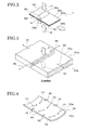
FIG. 2 is a schematic perspective view illustrating a main portion when thermally transferring the print onto one side face of a PC sheet in a two-side printing structure according toEmbodiment 1 of the present invention. -
FIG. 3 is a schematic perspective view illustrating recurve when thermally transferring the print to the one side face of the PC sheet in the two-side printing structure according toEmbodiment 1 of the present invention. -
FIG. 4 is an enlarged perspective view illustrating a recurve mechanism generated in a cooling step after thermally transferring the print onto the PC sheet by two-side printing as a comparative example of the two-side printing structure of the present invention. -
FIGs. 5A-5C are views each illustrating a manufacturing step which thermally transfers the print by two thermal transfer rollers at the same time in the two-side print structure according toEmbodiment 1 of the present invention;FIG. 5A is a longitudinal sectional view of a main portion illustrating a state in which a base material and two intermediate transfer films each including a print having print layers are attached to a two-side printer,FIG. 5B is a longitudinal sectional view of a main portion illustrating thermal transferring by the two thermal transfer rollers, andFIG. 5C is a longitudinal sectional view illustrating a state in which the intermediate transfer films are separated. -
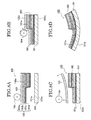
FIGs 6A-6E are views each illustrating a two-side printing structure according toEmbodiment 2 of the present invention;FIG. 6A is a longitudinal sectional view of a main portion illustrating a state in which a base material and an intermediate transfer film provided with a print having print layers are attached to a two-side printer,FIG. 6B is a longitudinal sectional view of a main portion illustrating thermal transferring by a thermal transfer roller,FIG. 6C is a longitudinal sectional view of a main portion illustrating a state in which the turned over base material and the intermediate transfer film provided with the print including the print layers are attached to the two-side printer,FIG. 6D is a longitudinal sectional view of a main portion illustrating thermal transferring by a thermal transfer roller andFIG. 6E is a longitudinal sectional view illustrating a sate in which the intermediate transfer roller is separated in a cooling step. -
FIG. 7 is a schematic longitudinal sectional view illustrating a lamination order of print layers constituting a main portion of a print in a conventional printing structure of a dial. -
FIGs. 8A-8D are schematic views each illustrating a manufacturing step which thermally transfers a print onto a PC sheet by one-side printing in the conventional printing structure of the dial;FIG. 8A is a longitudinal sectional view of a main portion illustrating a state in which a base material and an intermediate transfer film provided with a print having print layers are attached to a one-side printer,FIG. 8B is a longitudinal sectional view of a main portion illustrating thermal transferring by a thermal transfer roller, andFIG. 8C is a longitudinal sectional view illustrating a state in which the base material recurves in a cooling step. - Next, a two-side printing structure, a dial having the same and a printing method of the two-side printing structure according to embodiments of the present invention will be described with reference to
FIGs. 1-6 . - In addition, the same reference numbers are applied to portions which are the same as or similar to those in the prior art.
- At first, the configuration will be described. The two-side printing structure of each of the embodiments is used for a backlight transmissive dial, for example, a dial of an automotive indicator such as a speed meter (not shown) and a tachometer (not shown) disposed near a driver's seat in an automobile.
- Referring to
FIGs. 1-5 , adial 10 to which a two-side printing structure ofEmbodiment 1 is applied and a printing method of the two-side printing structure are illustrated. - At first, the configuration will be described. As illustrated in
FIG. 1 , thedial 10 ofEmbodiment 1 includes as a base material atransparent PC sheet 101 having one flat side face (first face) 101 a and another flat side face (second face) 101b as print faces. - The one
side face 101a includes aprint 103 having a plurality ofprint layers 103a-103h each having a different color. Each of the print layers 103a-103h is thermally transferred. The print layers 103a-103h are laminated in a state in which parts of the layers are overlapped. - The
other side face 101b also includes aprint 3 having asingle print layer 3a. - If light illuminated from the side of the
other side face 101b which is the back side of thePC sheet 101 of thedial 10 transmits to the side of the oneside face 101 a which is a surface side of thePC sheet 101 of thedial 10, the light passes through theprint layer 3a and eachprint layer 103a-103h or is reflected by theprint layer 3a and eachprint layer 103a-103h. - On the contrary, in this
Embodiment 1, if the light illuminated from the side of the oneside face 101a which is the surface side of thePC sheet 101 of thedial 10 transmits to the side of the other side face 10b which is the back side of thePC sheet 101 of thedial 10, the light passes through eachprint layer 103a-103h and theprint layer 3 a. - In this case, in a portion where the
print layer 3a is overlapped with any one of the print layers 103a-103h, the colors are mixed to be adjusted to desired colors, and the colors are visualized by a passenger in a passenger compartment provided with the display unit as the colors of the transmissive light of thedial 10. - In
Embodiment 1, since theprint 103 is applied to the oneside face 101a of thePC sheet 101 and theprint 3 is applied to theother side face 101b of thePC sheet 101, two PETintermediate transfer films - The
print 103 having a plurality ofprint layers 103a-103h is previously laminated on atransfer face 102a of oneintermediate transfer film 102 in a reverse order. Thesingle print layer 3a is previously attached to thetransfer face 102a of the otherintermediate transfer film 102. - Next, the printing method of the two-side printing structure of
Embodiment 1 will be described with reference to printing steps illustrated inFIGs. 5A-5C as a printing method using a two-sidethermal transfer printer 5 capable of thermally transferring onto two sides at the same time. - At first, the configuration of the two-side
thermal transfer printer 5 for use in this two-side printing will be described. As illustrated inFIGs. 2-4 , the two-sidethermal transfer printer 5 includes a pairthermal transfer rollers thermal transfer roller 104a is disposed on the side of the oneside face 101a of thePC sheet 101 and thethermal transfer rollers 104b is disposed on the side of theother side face 101b of thePC sheet 101. Thethermal transfer roller 104a rotates while pressing the PETintermediate transfer film 102 to the oneside face 101a and heating the PETintermediate transfer film 102 and thethermal transfer roller 104b rotates while pressing the PETintermediate transfer film 102 to theother side face 101b and heating the PETintermediate transfer film 102, so as to conduct the transfer printing. - Each of the
thermal transfer roller thermal transfer printer 5 includes a cylinder device (not shown) which moves in the direction which presses the side of eachtransfer face intermediate transfer film side face PC sheet 101. - As illustrated in
FIGs. 2, 3 , the cylinder device inEmbodiment 1 can output pressing strengths F1, F2 (F1 = 0.5MPa, F2 = 0.5MPa) in the up and down direction, and the driving direction comes close and separates in the opposing direction. Therefore, each of the pressing strengths F1, F2 from each of the two sides of the top and bottom is applied to the side of each of the side faces 101a, 101b of thePC sheet 101 disposed between theintermediate transfer films - The
PC sheet 101 provided between a pair ofthermal transfer rollers FIG. 2 by a traversing device (not shown), and is heated by thethermal transfer rollers - The temperature in the outer circumferential face of each of the
thermal transfer rollers - Namely, the surface temperature of the
intermediate transfer films thermal transfer rollers PC sheet 101. - In this case, similar to the thin
intermediate transfer film 102, the surface temperature of the surface to be transferred which is the surface side of thePC sheet 101 becomes 150°C or more but lower than 160°C. - The temperature of the back side of the
PC sheet 101 in the thermal transferring and pressing becomes lower than about 120°C which is lower than 141°C-149°C of a glass dislocation point by adjusting the thickness of thePC sheet 101. - Accordingly, as illustrated in
FIG. 2 , even if the thermal transfer is performed by thethermal transfer rollers PC sheet 101, if thethermal transfer roller 104a is only heated, as illustrated inFIG. 3 , the material close to the surface side significantly expands toward the four directions B1-B4 compared to the material close to the back side even though the pressing strength F1 is equal to the pressing strength F2. - Therefore, if the cooling step starts by the separation of the
thermal transfer roller 104a, the material close to the surface side of thePC sheet 101 contracts as illustrated inFIG. 4 , and the tensile forces F3, F4 act. Thereby, the surface side of thePC sheet 101 may recurve in a concave shape by the tensile forces F3, F4 acting on the side ends. - As described above, factors which determine the recurve amount are mainly the heat amount (temperature and time), the external stress (cylinder pressure) and the material (material and thickness).
- In order to reduce the recurve amount, it is necessary for the recurve amount generated on both of the side faces 101a, 101b of the
PC sheet 101 to be equal to each other. - Accordingly, in the two-side printing structure of
Embodiment 1, as illustrated inFIG. 5A , theprint 103 is thermally transferred onto theside face 101 a of thePC sheet 101 as a base material by thetransfer roller 104a and theprint 3 is thermally transferred onto theside face 101b of thePC sheet 101 as a base material by thethermal transfer roller 104b. Thereby, theprint layers 103a-103d are formed on theside face 101a and theprint layer 3 a is formed on theside face 101b, and at least a part of thePC sheet 101 operates as a design face of thedial 10. - As illustrated in 5B, the
transfer face 102a of theintermediate transfer film 102 provided with theprint layers 103a-103d which are transferred onto theside face 101a of thePC sheet 101 provided between thethermal transfer rollers transfer face 102a of theintermediate transfer film 102 provided with theprint layer 3 which is transferred onto theside face 101b of thePC sheet 101 provided between thethermal transfer rollers - In this case, in
Embodiment 1, the pressing strengths to the opposing direction function between thethermal transfer rollers PC sheet 101 becomes equal to the pressure to be applied to the back side of thePC sheet 101. - By the not shown traversing device, the
thermal transfer rollers FIG. 5B , and theintermediate transfer films PC sheet 101 by thethermal transfer rollers - The
thermal transfer rollers intermediate transfer films intermediate transfer films - As illustrated in
FIG. 5C , since theintermediate transfer films thermal transfer rollers prints - Next, the function and effect of the two-side printing structure, the dial using the two-side printing structure and the printing method of the two-side printing structure of
Embodiment 1 will be described. - In the two-side printing structure of
Embodiment 1, theprint 103 having theprint layers 103a-103d is thermally transferred onto the oneside face 101a and theprint 3 having theprint layer 3 a is thermally transferred onto theother side face 101b. - Therefore, heat and pressing strength are simultaneously applied to the two-side faces 101a, 101b of the
PC sheet 101 to be stretched, so that the two-sided faces - For this reason, even if the thermal transfer printing is performed, the
PC sheet 101 does not recurve and bend. - In the
dial 10 and the like in which the design face is formed on thePC sheet 101, since thePC sheet 101 provided with theprints - In
Embodiment 1, the thermal transfer step of theprint 103 to theside face 101a of thePC sheet 101 by thethermal transfer roller 104a and the thermal transfer step of theprint 3 to theside face 101b of thePC sheet 101 by thethermal transfer roller 104b are simultaneously performed. - Therefore, since the heat and pressing strengths are applied to the two-side faces 101a, 101b at the same time, the stretch and contraction ratios become the same between the two-side faces. Consequently, low sound between a portion which attaches the
dial 10 and a portion which supports thedial 10 is not caused, and also cracking is not caused. Accordingly, the generation of the recurve and bending, which deteriorates the external appearance of the design face of thedial 10 after being attached, can be controlled. -
FIGs. 6A-6E are views each illustrating a two-side printing structure, a dial using the two-side printing structure and a printing method of the two-side printing structure ofEmbodiment 2. - The same reference numbers are applied to the portions which are the same as those in Embodiment and
Embodiment 1. - At first, in the two-side printing structure, a
dial 20 having the two-side printing structure ofEmbodiment 2 and the printing method of the two-side printing structure, since the print is applied to the two-side faces 101a, 101b by independently performing the thermal transfer printing to each of the two-side faces 101a, 101b of thePC sheet 101, athermal transfer printer 15 having onethermal transfer roller 104 for one surface is used. - A
turnover mechanism 106, which can direct theside face 101a or theside face 101b of thePC sheet 101 upward or downward, is provided in the not shown traversing device. - The cylinder device is configured to drive at the same pressure when driving in the direction which presses toward each of the side faces 101a, 101b of the
PC sheet 101 even if the thickness of theprint 103 provided in theintermediate transfer film 102 is different from the thickness of theprint 3 provided in theintermediate transfer film 102. - Next, the function and effect of the two-side printing structure of the dial of
Embodiment 2 will be described. - In the two-side printing structure of
Embodiment 2 as described above, at first, as illustrated inFIG. 6A , thePC sheet 101 is attached to thethermal transfer printer 15 using onethermal transfer roller 104 and theprint 103 having a plurality ofprint layers 103a-103d has contact with the oneside face 101a of thePC sheet 101 from thetransfer face 102a of the PETintermediate transfer film 102 in which theprint layers 103a-103d are laminated in a reverse order. - Next, as illustrated in
FIG. 6B , thethermal transfer roller 104 rotates while pressing from theoutside face 102b of theintermediate transfer film 102 in a heated state. - The
transfer face 102a of theintermediate transfer film 102 is pressed to the oneside face 101a of thesoftened PC sheet 101. - The
print 103 having theprinting layers 103a-103d laminated on thetransfer face 102a is thereby fixed by pressure to the oneside face 101a of thePC sheet 101. - After fixing by applying pressure, as illustrated in
FIG. 6C , thethermal transfer roller 104 is removed, and the two-side faces 101a, 101b of thePC sheet 101 are turned over at 180 degrees by using theturnover mechanism 106 of the traversing device, such that theother side face 101b faces the side of thethermal transfer roller 104. - Then, the
intermediate transfer film 102 provided with theprint 103 to be transferred onto theother side face 101b is attached, and, as illustrated inFIG. 6D , theintermediate transfer film 102 is pressed by the heat of the rotatingthermal transfer roller 104 in a heated state. - The relative moving speed of the
thermal transfer roller 104 and thePC sheet 101 by the traversing device is a speed which is the same as that in the fixing by pressure to the side of the oneside face 101a. - The surface temperature of the
intermediate transfer film 102 to which the outer surface of thethermal transfer roller 104 has contact with becomes 150°C or more but lower than 160°C, and is adjusted to be the temperature which is the same as in the transferring of the oneside face 101a so as to exceed 141°C-149°C of a glass dislocation point of thePC sheet 101. - Then, as illustrated in
FIG. 6E , each of theprints intermediate transfer films softened PC sheet 101. - In the
dial 20 ofEmbodiment 2, the heating temperature, pressure and the like are set at the same conditions in the two-side faces 101a, 101b, so that even if thethermal transfer roller 104 for one surface is used, the thermal transfer print is independently applied to each of the two-side faces 101a, 101b of thePC sheet 101, and the print can be applied to the two-side faces 101a, 101b, and the freedom of design in the design face can be improved. - Since the other structures, function and effect of
Embodiment 2 are similar to those in Embodiment andEmbodiment 1, the description thereof will be omitted. - Although Embodiment and
Embodiments Embodiments - For instance, in each of Embodiment and
Embodiments - In Embodiments of the present invention, the pressing strengths F1, F2 (F1 = 0.5MPa, F2 = 0.5MPa) to be applied by the cylinder device are set to be the same. However, the pressing strength is not limited to thereto. The heating temperature by a heater, the number of rollers, the shape, the size and the material are not especially limited as long as the print can be thermally transferred.
- In the present embodiments, the
print 3 of theother side face 101b of thePC sheet 101 has a single print layer; however, a plurality of print layers can be provided on theother side face 101b. - Moreover, in the present embodiment, the temperature of the
thermal transfer rollers 104a is set to be the same as the temperature of thethermal transfer roller 104b; however, the temperature of thethermal transfer rollers thermal transfer roller 104b on the side of theother side face 101b of thePC sheet 101 can be controlled according to the temperature of thethermal transfer roller 104a on the side of the oneside face 101a of thePC sheet 101. Also, the temperature of thethermal transfer roller 104b on the side of theother side face 101b can be controlled according to the contraction degree of thePC sheet 101. - According to the embodiments of the present invention, the prints are thermally transferred onto the two-side faces of the base material, respectively.
- By this configuration, the heat and the pressing strength are applied to the two-side faces of the base material so that the two-side faces are stretched. Therefore, the two-side faces contact in the same way in the cooling step.
- Accordingly, even if the thermal transfer printing is performed, the base material does not recurve and bend.
- According to the embodiments of the present invention, even if the design face is provided at least in a part of the base material having prints, a preferable external appearance of the design face, which does not have bending such as recurve can be obtained.
- According to the embodiments of the present invention, the thermal transfer step which performs the printing to the two-side faces of the base material is simultaneously performed on the two-side faces of the base material.
- Therefore, since the heat and the pressure strength are simultaneously applied, the same stretch ratio is obtained in the two-side faces, so that the generation of the recurve and bending can be controlled.
- According to the embodiments of the present invention, since the heating temperature and the pressure strength are set by the same conditions on the two-side faces, the thermal transfer printing can be independently applied to each of the side faces of the base material even if the thermal transfer roller for one surface is used, so that the printing can be performed to both of the side faces.
Claims (10)
- A two-side printing structure, comprising:a base material (101) including a first face (101a) and a second face (101b) located on a side opposite to the first face (101a);a print (103) having a print layer provided on the first face (101a) of the base member (101) by thermal transfer printing; anda print (3) having a print layer provided on the second face (101b) of the base member (101) by thermal transfer printing.
- The two-side printing structure according to Claim 1, wherein the print (103) having the print layer provided on the first face (101a) of the base member (101) by the thermal transfer printing includes a plurality of print layers (103a-103h) having the print layer.
- The two-side printing structure according to Claim 1 or Claim 2, wherein the print layer provided on the second face (101b) of the base member (101) by the thermal transfer printing is a single layer (3a).
- A dial using the two-side printing structure according to Claim 1, wherein at least one of at least a part of the first face (101a) and at least a part of the second face (101b) is used as a design face.
- A printing method of a two-side printing structure, comprising the steps of:providing a print (103) on a first face (101a) of a base material (101) by thermal transfer printing; andproviding a print (3) on a second face (101b) located on a side opposite to the first face of the base material (101) by thermal transfer printing.
- The printing method of a two-side printing structure according to claim 5, wherein the print (103) is provided on the first face (101a) and the print (3) is provided on the second face (101b) by individually performing the thermal transfer printing on the first face (101a) and the second face (101b) of the base material (101).
- The printing method of a two-side printing structure according to claim 5, wherein the thermal transfer printing is performed on the second face (101b) at the same time as the thermal transfer printing on the first face (101a).
- The printing method of a two-side printing structure according to claim 5, wherein the thermal transfer printing is performed on the second face (101b) after performing the thermal transfer printing on the first face (101a).
- The printing method of a two-side printing structure according to claim 5, wherein a heat temperature to be applied to the second face (101b) in the thermal transfer printing on the second face (101b) is the same as a heating temperature to be applied to the first face (101a) in the thermal transfer printing on the first face (101a).
- The printing method of a two-side printing structure according to claim 5, wherein when performing the thermal transfer printing on the first face (101a), the first face is pressed, and when performing the thermal transfer printing on the second face (101b), the second face is pressed by a pressure which is the same as a pressure to the first face.
Applications Claiming Priority (1)
| Application Number | Priority Date | Filing Date | Title |
|---|---|---|---|
| JP2010041683A JP2011177910A (en) | 2010-02-26 | 2010-02-26 | Double-side printing structure, dial using the same and printing method of the double-side printing structure |
Publications (2)
| Publication Number | Publication Date |
|---|---|
| EP2362370A2 true EP2362370A2 (en) | 2011-08-31 |
| EP2362370A3 EP2362370A3 (en) | 2015-02-11 |
Family
ID=44070760
Family Applications (1)
| Application Number | Title | Priority Date | Filing Date |
|---|---|---|---|
| EP20110155198 Withdrawn EP2362370A3 (en) | 2010-02-26 | 2011-02-21 | Two-side printing structure, dial using the same and printing method of two-side printing structure |
Country Status (4)
| Country | Link |
|---|---|
| US (1) | US20110209637A1 (en) |
| EP (1) | EP2362370A3 (en) |
| JP (1) | JP2011177910A (en) |
| CN (1) | CN102169654B (en) |
Families Citing this family (4)
| Publication number | Priority date | Publication date | Assignee | Title |
|---|---|---|---|---|
| JP5890131B2 (en) * | 2011-09-13 | 2016-03-22 | 矢崎総業株式会社 | Manufacturing method of metal instrument panel |
| EP3348411B1 (en) * | 2015-09-30 | 2019-08-07 | Dai Nippon Printing Co., Ltd. | Thermal transfer image receiving sheet |
| CN106739610A (en) * | 2016-12-27 | 2017-05-31 | 安徽星光标识系统有限公司 | A kind of manufacture craft for printing label |
| EP3955275A4 (en) * | 2019-06-07 | 2023-01-18 | Sekisui Polymatech Co., Ltd. | Sensor-sheet-containing exterior article |
Citations (2)
| Publication number | Priority date | Publication date | Assignee | Title |
|---|---|---|---|---|
| JP2008257054A (en) | 2007-04-06 | 2008-10-23 | Dainippon Printing Co Ltd | Variable display structure |
| JP2008256996A (en) | 2007-04-06 | 2008-10-23 | Calsonic Kansei Corp | Printing structure |
Family Cites Families (18)
| Publication number | Priority date | Publication date | Assignee | Title |
|---|---|---|---|---|
| CA1222874A (en) * | 1984-07-18 | 1987-06-16 | Colin N. O'donoghue | Clock |
| JPH0345163U (en) * | 1989-09-06 | 1991-04-25 | ||
| JPH03114897A (en) * | 1989-09-29 | 1991-05-16 | Victor Co Of Japan Ltd | Ohp image-receiving paper for thermal transfer recording |
| US5284816A (en) * | 1992-11-19 | 1994-02-08 | Eastman Kodak Company | Two-sided thermal printing system |
| JPH06286292A (en) * | 1993-04-06 | 1994-10-11 | Masayuki Hayashi | Method of printing to synthetic resin board by heat transfer |
| EP0739751A3 (en) * | 1995-04-25 | 1997-10-22 | Fuji Photo Film Co Ltd | Image forming method |
| US6228805B1 (en) * | 1996-01-29 | 2001-05-08 | Dai Nippon Printing Co., Ltd. | Thermal transfer printing sheet and process of double-side transfer printing |
| JP3752296B2 (en) * | 1996-01-29 | 2006-03-08 | 大日本印刷株式会社 | Thermal transfer sheet and double-sided transfer method |
| JP3539840B2 (en) * | 1997-06-05 | 2004-07-07 | パイオニア株式会社 | Apparatus and method for producing double-sided recording paper for thermal transfer, and double-sided recording paper for thermal transfer |
| JP2000002564A (en) * | 1998-06-17 | 2000-01-07 | Denso Corp | Dial for vehicle display |
| JP2001225499A (en) * | 2000-02-17 | 2001-08-21 | Dainippon Printing Co Ltd | Thermal transfer recording method and thermal transfer recording apparatus |
| GB0108199D0 (en) * | 2001-04-02 | 2001-05-23 | Dupont Teijin Films Us Ltd | Multilayer film |
| US6795104B2 (en) * | 2001-12-26 | 2004-09-21 | Canon Kabushiki Kaisha | Thermal transfer recording apparatus, thermal transfer recording process and ink sheet |
| JP4689232B2 (en) * | 2004-10-26 | 2011-05-25 | カルソニックカンセイ株式会社 | Variable display structure |
| JP4929655B2 (en) * | 2005-09-14 | 2012-05-09 | 株式会社デンソー | Instrument display board |
| ATE554941T1 (en) * | 2006-11-14 | 2012-05-15 | Contra Vision Ltd | IMPROVEMENTS TO PRINTING OVERLAYED LAYERS |
| US8848010B2 (en) * | 2007-07-12 | 2014-09-30 | Ncr Corporation | Selective direct thermal and thermal transfer printing |
| CN101508222A (en) * | 2009-03-23 | 2009-08-19 | 郑佩玲 | Pattern printing method on shell and decorative panel of electronic products |
-
2010
- 2010-02-26 JP JP2010041683A patent/JP2011177910A/en active Pending
- 2010-09-16 CN CN201010287313.1A patent/CN102169654B/en not_active Expired - Fee Related
-
2011
- 2011-01-19 US US13/009,110 patent/US20110209637A1/en not_active Abandoned
- 2011-02-21 EP EP20110155198 patent/EP2362370A3/en not_active Withdrawn
Patent Citations (2)
| Publication number | Priority date | Publication date | Assignee | Title |
|---|---|---|---|---|
| JP2008257054A (en) | 2007-04-06 | 2008-10-23 | Dainippon Printing Co Ltd | Variable display structure |
| JP2008256996A (en) | 2007-04-06 | 2008-10-23 | Calsonic Kansei Corp | Printing structure |
Also Published As
| Publication number | Publication date |
|---|---|
| JP2011177910A (en) | 2011-09-15 |
| CN102169654A (en) | 2011-08-31 |
| CN102169654B (en) | 2014-04-02 |
| US20110209637A1 (en) | 2011-09-01 |
| EP2362370A3 (en) | 2015-02-11 |
Similar Documents
| Publication | Publication Date | Title |
|---|---|---|
| EP2362370A2 (en) | Two-side printing structure, dial using the same and printing method of two-side printing structure | |
| KR101511216B1 (en) | Curved glass thermal transferring method by cutting print film | |
| JP2023168358A (en) | Cold molded laminate | |
| US8721933B2 (en) | Optical sheet manufacture method and optical sheet | |
| US20110242141A1 (en) | Optical sheet laminate body, illumination unit, and display unit | |
| JP2019524614A (en) | Laminating thin tempered glass on curved molded plastic surfaces for decorative and display cover applications | |
| JP2003011218A (en) | Manufacturing method of micro embossed sheet and micro embossed sheet | |
| JP2013022754A (en) | Method for manufacturing image print transfer sheet, image print transfer sheet, and image transfer method | |
| CN217672165U (en) | Glass products and vehicle interior systems having the same | |
| US6640866B2 (en) | Laminator assembly having an improved dual durometor lamination roller | |
| JP4533542B2 (en) | Manufacturing method of micro embossed sheet | |
| TW202100357A (en) | Cold formed 3d product and processes using vacuum chuck | |
| JP5111800B2 (en) | Sheet forming equipment | |
| EP1066979A3 (en) | High-sensitive stencil sheet and method for producing the same | |
| JP2001253621A (en) | Warp correcting device and method | |
| CN110958939A (en) | Decorative design element in black print | |
| JPH0867016A (en) | Recording device using an intermediate transfer member | |
| JP2004170856A (en) | Color fixing device | |
| KR102919261B1 (en) | Method for manufacturing compressed modular OCA film with pattern printing for UTG | |
| JPH0511155U (en) | Gloss processor | |
| JP2006267392A (en) | Image fixing device | |
| JP2971368B2 (en) | Thermal transfer roll for manufacturing a laminated plate, a method for heating a thin metal plate using the thermal transfer roll, and a laminate manufacturing apparatus equipped with the thermal transfer roll | |
| TW202614904A (en) | Cold-formed oled displays and methods for fabricating the same | |
| JP2025000482A (en) | Decorative sheet attaching method, decorative sheet molding method, and decorative sheet processing device, and pre-molding jig | |
| JP4272439B2 (en) | Method for producing thermoplastic resin sheet |
Legal Events
| Date | Code | Title | Description |
|---|---|---|---|
| PUAI | Public reference made under article 153(3) epc to a published international application that has entered the european phase |
Free format text: ORIGINAL CODE: 0009012 |
|
| AK | Designated contracting states |
Kind code of ref document: A2 Designated state(s): AL AT BE BG CH CY CZ DE DK EE ES FI FR GB GR HR HU IE IS IT LI LT LU LV MC MK MT NL NO PL PT RO RS SE SI SK SM TR |
|
| AX | Request for extension of the european patent |
Extension state: BA ME |
|
| PUAL | Search report despatched |
Free format text: ORIGINAL CODE: 0009013 |
|
| AK | Designated contracting states |
Kind code of ref document: A3 Designated state(s): AL AT BE BG CH CY CZ DE DK EE ES FI FR GB GR HR HU IE IS IT LI LT LU LV MC MK MT NL NO PL PT RO RS SE SI SK SM TR |
|
| AX | Request for extension of the european patent |
Extension state: BA ME |
|
| RIC1 | Information provided on ipc code assigned before grant |
Ipc: G09F 3/02 20060101ALI20150107BHEP Ipc: G01D 13/04 20060101ALI20150107BHEP Ipc: B41M 3/12 20060101AFI20150107BHEP Ipc: B60K 37/02 20060101ALI20150107BHEP Ipc: G09F 13/08 20060101ALI20150107BHEP Ipc: G04B 19/12 20060101ALI20150107BHEP Ipc: G09F 19/12 20060101ALI20150107BHEP |
|
| STAA | Information on the status of an ep patent application or granted ep patent |
Free format text: STATUS: THE APPLICATION IS DEEMED TO BE WITHDRAWN |
|
| 18D | Application deemed to be withdrawn |
Effective date: 20150812 |