EP2362210A1 - Fluid sensor and method of using same - Google Patents
Fluid sensor and method of using same Download PDFInfo
- Publication number
- EP2362210A1 EP2362210A1 EP10290084A EP10290084A EP2362210A1 EP 2362210 A1 EP2362210 A1 EP 2362210A1 EP 10290084 A EP10290084 A EP 10290084A EP 10290084 A EP10290084 A EP 10290084A EP 2362210 A1 EP2362210 A1 EP 2362210A1
- Authority
- EP
- European Patent Office
- Prior art keywords
- fluid
- base
- wellbore
- fluid sensor
- electrode
- Prior art date
- Legal status (The legal status is an assumption and is not a legal conclusion. Google has not performed a legal analysis and makes no representation as to the accuracy of the status listed.)
- Granted
Links
- 239000012530 fluid Substances 0.000 title claims abstract description 144
- 238000000034 method Methods 0.000 title claims abstract description 25
- 238000009413 insulation Methods 0.000 claims abstract description 35
- 238000005553 drilling Methods 0.000 claims description 15
- 238000004519 manufacturing process Methods 0.000 claims description 13
- 238000012544 monitoring process Methods 0.000 claims description 2
- 238000005259 measurement Methods 0.000 description 16
- 238000004891 communication Methods 0.000 description 7
- 229930195733 hydrocarbon Natural products 0.000 description 6
- 150000002430 hydrocarbons Chemical class 0.000 description 6
- 238000004458 analytical method Methods 0.000 description 4
- 238000012360 testing method Methods 0.000 description 3
- 239000004215 Carbon black (E152) Substances 0.000 description 2
- RYGMFSIKBFXOCR-UHFFFAOYSA-N Copper Chemical compound [Cu] RYGMFSIKBFXOCR-UHFFFAOYSA-N 0.000 description 2
- 239000003990 capacitor Substances 0.000 description 2
- 229910052802 copper Inorganic materials 0.000 description 2
- 239000010949 copper Substances 0.000 description 2
- 230000015572 biosynthetic process Effects 0.000 description 1
- 238000010276 construction Methods 0.000 description 1
- 239000000356 contaminant Substances 0.000 description 1
- 238000007796 conventional method Methods 0.000 description 1
- 238000005520 cutting process Methods 0.000 description 1
- 238000011161 development Methods 0.000 description 1
- 238000001312 dry etching Methods 0.000 description 1
- 230000000694 effects Effects 0.000 description 1
- 238000005516 engineering process Methods 0.000 description 1
- PCHJSUWPFVWCPO-UHFFFAOYSA-N gold Chemical compound [Au] PCHJSUWPFVWCPO-UHFFFAOYSA-N 0.000 description 1
- 229910052737 gold Inorganic materials 0.000 description 1
- 239000010931 gold Substances 0.000 description 1
- 238000003384 imaging method Methods 0.000 description 1
- 239000011499 joint compound Substances 0.000 description 1
- 239000000463 material Substances 0.000 description 1
- 238000012986 modification Methods 0.000 description 1
- 230000004048 modification Effects 0.000 description 1
- 238000012806 monitoring device Methods 0.000 description 1
- 230000003647 oxidation Effects 0.000 description 1
- 238000007254 oxidation reaction Methods 0.000 description 1
- 230000001681 protective effect Effects 0.000 description 1
- 239000011347 resin Substances 0.000 description 1
- 229920005989 resin Polymers 0.000 description 1
- 238000005070 sampling Methods 0.000 description 1
- 230000035945 sensitivity Effects 0.000 description 1
- 238000003860 storage Methods 0.000 description 1
- XLYOFNOQVPJJNP-UHFFFAOYSA-N water Substances O XLYOFNOQVPJJNP-UHFFFAOYSA-N 0.000 description 1
- 238000001039 wet etching Methods 0.000 description 1
Images


Classifications
-
- G—PHYSICS
- G01—MEASURING; TESTING
- G01N—INVESTIGATING OR ANALYSING MATERIALS BY DETERMINING THEIR CHEMICAL OR PHYSICAL PROPERTIES
- G01N27/00—Investigating or analysing materials by the use of electric, electrochemical, or magnetic means
- G01N27/02—Investigating or analysing materials by the use of electric, electrochemical, or magnetic means by investigating impedance
- G01N27/04—Investigating or analysing materials by the use of electric, electrochemical, or magnetic means by investigating impedance by investigating resistance
- G01N27/06—Investigating or analysing materials by the use of electric, electrochemical, or magnetic means by investigating impedance by investigating resistance of a liquid
-
- G—PHYSICS
- G01—MEASURING; TESTING
- G01N—INVESTIGATING OR ANALYSING MATERIALS BY DETERMINING THEIR CHEMICAL OR PHYSICAL PROPERTIES
- G01N33/00—Investigating or analysing materials by specific methods not covered by groups G01N1/00 - G01N31/00
- G01N33/26—Oils; viscous liquids; paints; inks
- G01N33/28—Oils, i.e. hydrocarbon liquids
- G01N33/2823—Oils, i.e. hydrocarbon liquids raw oil, drilling fluid or polyphasic mixtures
Definitions
- the present invention relates to techniques for determining fluid parameters. More particularly, the present invention relates to techniques for determining electrical parameters of downhole fluids.
- Oil rigs are positioned at wellsites for performing a variety of oilfield operations, such as drilling a wellbore, performing downhole testing and producing located hydrocarbons.
- Downhole drilling tools are advanced into the earth from a surface rig to form a wellbore.
- Drilling muds are often pumped into the wellbore as the drilling tool advances into the earth.
- the drilling muds may be used, for example, to remove cuttings, to cool a drill bit at the end of the drilling tool and/or to provide a protective lining along a wall of the wellbore.
- casing is typically cemented into place to line at least a portion of the wellbore.
- production tools may be positioned about the wellbore to draw fluids to the surface.
- drilling tool may be removed so that a wireline testing tool may be lowered into the wellbore to take additional measurements and/or to sample downhole fluids.
- production equipment may be lowered into the wellbore to assist in drawing the hydrocarbons from a subsurface reservoir to the surface.
- the downhole measurements taken by the drilling, testing, production and/or other wellsite tools may be used to determine downhole conditions and/or to assist in locating subsurface reservoirs containing valuable hydrocarbons.
- Such wellsite tools may be used to measure downhole parameters, such as temperature, pressure, viscosity, resistivity, etc. Such measurements may be useful in directing the oilfield operations and/or for analyzing downhole conditions.
- Such techniques involve one or more of the following, among others: accuracy of measurements, optimized measurement processes, reduced clogging, minimized components, reduced size, increased surface area for measurement, constant flow of fluids during measurement, optimized shape of measurement apparatus/system, real time capabilities, compatibility with existing wellsite equipment, operability in downhole conditions (e.g., at high temperatures and/or pressures), etc.
- the present invention relates to a fluid sensor for determining at least one parameter of a fluid of a wellbore.
- the fluid sensor has a base positionable in the wellbore, a base electrode, and a raised electrode.
- the base comprises insulation.
- the base electrode is operatively positionable in the insulation.
- the raised electrode has at least one base portion and at least one raised portion.
- the base portion is operatively positionable in the insulation.
- the raised portion is positionable a distance above the base electrode such that a space is defined therebetween for the passage of the wellbore fluid therethrough.
- a voltage is applied across the base electrode and the raised electrode to generate a current therebetween whereby at least one parameter of the wellbore fluid may be determined.
- the present invention also relates to a system for determining at least one parameter of a fluid in a wellbore.
- the system includes a downhole tool positionable in the wellbore and a fluid sensor.
- the fluid sensor has a base positionable in the wellbore, a base electrode, and a raised electrode.
- the base comprises insulation.
- the base portion is operatively positionable in the insulation.
- the raised electrode has at least one base portion and at least one raised portion.
- the raised portion is positionable a distance above the base electrode such that a space is defined therebetween for the passage of the wellbore fluid therethrough.
- a voltage is applied across the base electrode and the raised electrode to generate a current therebetween whereby at least one parameter of the wellbore fluid may be determined.
- the present invention relates to a method for determining at least one parameter of a fluid in a wellbore.
- the method involves providing a fluid sensor.
- the fluid sensor has a base positionable in the wellbore, a base electrode, and a raised electrode.
- the base comprises insulation.
- the base electrode is operatively positionable in the insulation.
- the raised electrode has at least one base portion and at least one raised portion.
- the base portion is operatively positionable in the insulation.
- the raised portion is positionable a distance above the base electrode such that a space is defined therebetween for the passage of the wellbore fluid therethrough.
- the method further involves positioning a downhole tool into the wellbore with the fluid sensor thereon, receiving a downhole fluid between the pair of electrodes, applying a voltage across the pair of electrodes to generate a current therebetween, and determining the at least one fluid parameter from the generated current.
- Figure 1 is a schematic view of a wellsite 100 having an oil rig 102 with a downhole tool 104 suspended into a wellbore 106 therebelow.
- the wellbore 106 has been drilled by a drilling tool (not shown).
- a drilling mud 108 has been pumped into the wellbore 106 and lines a wall thereof.
- a casing 110 has also been positioned in the wellbore 106 and cemented into place therein.
- the downhole tool 104 is shown as a wireline logging tool lowered into the wellbore 106 to take various measurements.
- the downhole tool 104 has a conventional logging device 112 therein that may be provided with various sensors, measurement devices, communication devices, sampling devices and/or other devices for performing wellbore operations.
- a conventional logging device 112 therein that may be provided with various sensors, measurement devices, communication devices, sampling devices and/or other devices for performing wellbore operations.
- the downhole tool 104 may use devices known in the art, such as resistivity or other logging devices, to measure formation properties.
- the downhole tool 104 is operatively connected to a surface unit 114 for communication therebetween.
- the downhole tool 104 may be wired via the wireline 116 as shown and/or wirelessly linked via telemetry devices 117, such as conventional electromagnetic devices known in the art, for passing signals to a surface unit 114 as indicated by communication links 118. Signals may be passed between the downhole tool 104 and the surface unit 114 and/or other locations for communication therebetween.
- the downhole tool 104 is also provided with a fluid sensor 120 for determining downhole fluid parameters.
- the fluid sensor 120 is preferably capable of determining parameters of downhole fluids, such as downhole mud (e.g., oil based), hydrocarbons, water and/or other downhole fluids. Additionally, the fluid sensor 120 is preferably capable of determining parameters of downhole fluids as the downhole tool 104 passes through the wellbore 106. Due to the harsh conditions of the downhole environment, the fluid sensor 120 is preferably positioned on the downhole tool 104 in such a manner that the fluid sensor is capable of receiving fluids as the downhole tool 104 passes through the wellbore 106, and that reduces clogging of such fluids as fluids pass through the fluid sensor 120.
- the fluid sensor 120 is positioned on an outer surface 122 of the downhole tool 104.
- the fluid sensor 120 may be recessed a distance below the outer surface 122 to provide additional protection thereto, or protruded a distance therefrom to access fluid.
- the fluid sensor 120 may also be positioned at various angles as desired.
- the fluid sensor 120 is also depicted as being positioned on production monitoring devices 104'.
- the production monitors 104' may be conventional production monitors as known in the art. These production monitors 104' are typically positioned about the well as shown for monitoring the production of fluids through the wellbore 106.
- the fluid sensors 120 are positioned on an outer surface 124 of one or more of the production monitors 104'.
- the downhole tool 104 is depicted as a wireline tool 104 and a production monitor 104' with the fluid sensor 120 thereon, it will be appreciated that the fluid sensor 120 may be positioned downhole on a variety of one or more tools.
- the fluid sensor 120 may be placed downhole on a drilling, coiled tubing, drill stem tester, production, casing, pipe, or other downhole tool.
- the fluid sensor 120 is preferably positioned about an outer surface of the downhole tool so that fluid may pass therealong for measurement thereof.
- one or more fluid sensors 120 may be positioned at various locations about the wellsite as desired for performing fluid measurement.
- a power source 126 is operatively connected to the fluid sensor 120 for applying an AC voltage thereto at a frequency of between about tens of Hz to a few GHz.
- the power source 126 may be provided by a battery, power supply or other conventional means of providing power. In some cases, the power source 126 may be an existing power source used in the downhole tool.
- the power source 126 may be positioned, for example, in the downhole tool 104 and wired to the fluid sensor 120 for providing power thereto as shown.
- the power source 126 may be provided for use with the fluid sensor 120 and/or other downhole devices.
- the power source 126 may be positioned within the fluid sensor 120 or separate therefrom.
- the fluid sensor 120 may also be wired or wirelessly connected to other features of the downhole tool, such as communication links, processors, power sources or other features thereof.
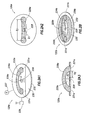
- FIGS 2A-2E show detailed views of various configurations 120a-e usable as the fluid sensor 120 of Figure 1 .
- Each fluid sensor 120a-e comprises a pair of electrodes 228,229a-e positioned in insulation 230 on a base (or pad) 232.
- Part or all of the base 232 may comprise the insulation 230.
- the base 232 may be adhered to the outer surface 122 of the downhole tool (e.g., 104 and/or 104' in Figure 1 ) using any conventional means.
- the insulation 230 may be adhered to the base 232 using any conventional means.
- the insulation 230 is preferably a material, such as a polymide resin, capable of providing insulation about the electrodes 228,229a-e.
- the insulation 230 may be provided with a thin layer of copper thereon, with a layer of gold applied to the copper to prevent oxidation (not shown).
- the electrodes 228,229a-e may be applied into the insulation 230 in the desired configuration using, for example, printed circuit board technology, wet or dry etching, and/or other conventional electronics construction technique.
- the electrodes 228,229a-e may be any conventional electrode capable of generating current across a fluid.
- a power source e.g., power source 126 of Figure 1
- the electrodes 228,229a-e are combined to form a capacitor for measuring current flowing therebetween.
- the electrodes 228,229a-e are preferably positioned such that capacitances are achieved between the surfaces of the electrodes 228,229a-e as wellbore fluids pass therebetween. As voltage is applied, a current flows out of one of the electrodes that can be measured.
- the current from the electrodes may be used to determine various parameters.
- an AC voltage V is applied between two parallel plates to generate a resultant current I that can be measured at either electrode.
- An impedance generated from the electrodes may consist of two capacitances in parallel, such as the capacitances between the electrodes interfacing with the wellbore fluid and interfacing with the insulation.
- the constant k may be measured empirically, for example, by measuring the impedance V / I between electrodes as a fluid of known impedivity is passed therethrough.
- the constant k may also be calculated from the geometry of the electrodes using conventional methods.
- Data concerning the measured current may be used to determine fluid parameters, such as impedivity, resistivity, impedence, general conductivity, complex conductivity, complex permittivity, tangent delta, and combinations thereof, as well as other parameters of the wellbore fluid.
- the data may be analyzed to determine characteristics of the wellbore fluid, such as the type of fluid (e.g., hydrocarbon, mud, contaminants, etc.)
- a processor e.g., logging device 112 of Figure 1
- the data may be communicated to the surface unit 114 and/or other location for storage and/or analysis. Such analysis may be performed with other inputs, such as historical or measured data about this or other wellsites. Reports and/or other outputs may be generated from the data.
- the data may be used to make decisions and/or adjust operations at the wellsite. In some cases, the data may be fed back to the wellsite for real-time decision making and/or operation.
- the electrodes 228,229a-e of the fluid sensor 120 are configured to optimize measurement of fluid passing therebetween.
- the insulating base is preferably of a small dimension having a surface area of about 1 cm 2 .
- the raised (i.e. arch) electrode fits within the base and has about the same overall dimensions.
- the base electrode is preferably smaller, having a surface are of a few square millimeters.
- Electrodes 229a-e are in a raised configuration relative to electrodes 228 to enable fluid flow therebetween.
- a voltage may be applied across the electrodes 228,229a-e.
- the voltage may be, for example, an AC voltage signal at a frequency of between about 10 Hz and 5 GHz.
- the electrodes 228,229a-e are preferably positioned with a space therebetween, to act as a capacitor with a current flowing thereacross.
- the electrodes are preferably configured for sensitivity to, for example, wellbore mud. The current flowing from either electrode 228,229a-e may be measured as described above.
- the information gathered preferably provides information sufficient to determine various fluid parameters and/or to identify the type of fluid (e.g., hydrocarbon, mud, etc.) This information may be used for further analysis, for example to provide micro-resistivity imaging of the wellbore. The information may also be used to locate and/or characterize reservoirs.
- type of fluid e.g., hydrocarbon, mud, etc.
- This information may be used for further analysis, for example to provide micro-resistivity imaging of the wellbore.
- the information may also be used to locate and/or characterize reservoirs.
- the fluid sensor 120 may be operatively connected to devices for operation therewith. As shown in Figure 2A1 , a downhole sensor 237 may be provided to measure various wellbore parameters. A transceiver 239 may also be provided for communication with the fluid sensor 120. For example, the transceiver 239 may communicate wirelessly with the logging tool 112 (see Figure 1 ). A communication link may also be provided with a wired connection between the fluid sensor 120 and the logging tool 112. The fluid sensor 120 may communicate with the surface unit 114 directly, or via the downhole tool 104.
- FIGS 2A1, 2A2 and 2A3 depict a fluid sensor 120a with a raised arch configuration.
- Electrode 228 is positioned in insulation 230 of base 232.
- Electrode 229a has two anchors 231a at each end thereof. The anchors 231a are positioned in insulation 230 of base 232. In this configuration, the electrode 229a has a raised portion 234a positioned a distance above the base 232 and electrode 228 to define a space 233a therebetween for the flow of fluid therethrough.
- Figure 2A2 is a plan view of the fluid sensor 120a of Figure 2A1 .
- the electrode 228 is preferably positioned underneath a central portion of electrode 229a.
- the length 11 of the electrode 228 is preferably about 5mm 2 or less.
- the length 12 of electrode 229a is preferably about 25mm or less.
- Figure 2A3 shows an elevational view of the fluid sensor 120a of Figure 2A1 .
- a distance d1 is defined in a space 233a between the electrode 228 and the electrode 229a at its highest point as shown. The space between the electrodes in this raised direction is sufficient to prevent clogging, for example, about 2-3 mm.
- a distance d2 is defined between electrode 228 and anchor 231a as shown. Preferably, the distance d1 is smaller by a factor of about two or more than the distance d2, for example, at about 4-6 mm.
- Figures 2B-2E2 depict various embodiments of the fluid sensor 120c-e having a raised portion 234b-e and a base portion 236b-e.
- the fluid sensors 120c-e may include a base 232 comprising insulation 230 as described, for example, with respect to Figure 2A1 , and an electrode 228 positioned in the insulation 230 on base 232 (not shown on Figures 2C1-2E2 ).
- the electrodes 229b-e are operatively connected in the insulation 230 of the base 232 in various raised configurations over electrodes 228 with a space 233b defined therebetween.
- Figure 2B shows an alternate version 120b of the raised arch fluid sensor 120a of Figures 2A1-2A3 .
- This configuration is the same as the fluid sensor 120a, except that electrode 229b has a base portion 236b coupled to the raised portion 234b.
- the base portion 236b is an elliptical loop positioned in insulation 230 of base 232, and encircling electrode 228.
- Raised portion 234b may be anchored to the electrode 229b via anchors 231b.
- the raised portion 234b may be integral with the base portion 236b, or operatively coupled to the base portion 236b and/or electrode 229b via the anchors 231b. As shown in this configuration, the base portion 236b may act in conjunction with or in place of anchor 231b.
- Figures 2C1-2C2 depict top and elevational views, respectively, of a fluid sensor 120c in a raised cross configuration.
- the electrode 229c has an oval portion 236c that forms a loop positioned in insulation 230 of base 232 (not shown), and two raised arches 234c1,c2 operatively connected to the oval base portion 236c.
- the two raised arches 234c1,c2 are operatively connected perpendicular to each other to form a cross as seen in the top view of Figure 2C1 .
- the raised arch 234c1 is depicted as being attached to the oval base portion 236c at the widest part thereof.
- the raised arch 234c2 is depicted as being attached to the oval portion 229c at the longest part thereof.
- the raised arches 234c1,c2 are unitary with each other and base portion 236c.
- a space 233c is defined between the electrodes 229c and 228 as shown in Figure 2C2 .
- Figures 2D1-2D2 depict top and elevational views, respectively, of a fluid sensor 120d in a raised X configuration.
- the electrode 229d has a square base portion 236d that forms a loop positioned in insulation 230 of base 232 (not shown), and two raised arches 234d are operatively connected to the oval base portion 236d.
- the two raised arches 234d connect at a peak to form an X as seen in the top view of Figure 2D1 .
- the raised arches 234d are depicted as being attached to the square base portion 236d at the coners thereof. As shown, the raised arches 234d are unitarily with each other and base portion 236d.
- a space 233d is defined between the electrodes 229d and 228 as shown in Figure 2D2 .
- Figures 2E1-2E2 depict top and elevational views, respectively, of a fluid sensor 120e in a raised grid configuration.
- the electrode 229e has an rectangular base portion 236e positioned in insulation 230 of base 232 (not shown), and multiple raised arches 234e1,e2 operatively connected to the rectangular base portion 236e.
- the two raised arches 234e1,e2 are operatively connected to form a grid as seen in the top view of Figure 2E1 .
- Two raised arches 234e1 are depicted as being attached to the rectangular base portion 236e at the longest part thereof.
- Three raised arches 234e2 are depicted as being attached to a short side of rectangular base portion 236e at the longest part thereof.
- the raised arches 234e1,e2 are unitarily with each other and base portion 236e.
- a space 233e is defined between the electrodes 229e and 228 as shown in Figure 2E2 .
- the base 232 and/or insulation 230 thereon may be of any shape.
- the base 232 is preferably a loop positioned about the electrode 228.
- the shape of the looped base may be elliptical as shown in Figures 2A1-C2 , square as shown in Figures 2D1-2 or rectangular as shown in Figures 2E1-2 .
- the electrode 228 is positioned centrally below the electrode 229b-e.
- Electrode 229b-e is preferably positioned such that portions of the electrode are positioned symmetrically about the electrode 228.
- the fluid sensors 120a-e may be positioned at a desired angle such that the electrodes 228,229a-e are positioned in a desired direction.
- Figure 3 is a flow chart depicting a method (350) of determining at least one parameter of a wellbore fluid.
- the method involved positioning (352) a downhole tool 104 with a fluid sensor 120 thereon into a wellbore 106 (see, e.g., Figure 1 ).
- a downhole fluid 108 is received (354) between electrodes of the fluid sensor 120.
- a voltage is applied (356) across electrodes 228,229a-e of the fluid sensor 120 to generate a current therebetween (see, e.g., Figures 2A-2D ).
- Parameters may be determined (358) from the current generated from the electrodes.
- Data may be collected (360) concerning the wellsite. This data may be data from the fluid sensor 120, the downhole sensor 233, historical or other data. The collected data may be analyzed (362) and reports generated (364). Actions, such as adjusting wellsite operations, may be taken (366) based on the analysis. The steps of the method may be repeated (368) continuously or at discrete locations as the downhole tool 104 is moving through the wellbore. Various combinations of the steps of the method may be performed in a desired order using one or more downhole tools 104 and/or one or more fluid sensors 120.
- the one or more fluid and/or other sensors may be positioned about the wellsite to measure and/or collect data.
Abstract
Description
- The present invention relates to techniques for determining fluid parameters. More particularly, the present invention relates to techniques for determining electrical parameters of downhole fluids.
- Oil rigs are positioned at wellsites for performing a variety of oilfield operations, such as drilling a wellbore, performing downhole testing and producing located hydrocarbons. Downhole drilling tools are advanced into the earth from a surface rig to form a wellbore. Drilling muds are often pumped into the wellbore as the drilling tool advances into the earth. The drilling muds may be used, for example, to remove cuttings, to cool a drill bit at the end of the drilling tool and/or to provide a protective lining along a wall of the wellbore. During or after drilling, casing is typically cemented into place to line at least a portion of the wellbore. Once the wellbore is formed, production tools may be positioned about the wellbore to draw fluids to the surface.
- During drilling, measurements are often taken to determine downhole conditions. In some cases, the drilling tool may be removed so that a wireline testing tool may be lowered into the wellbore to take additional measurements and/or to sample downhole fluids. Once the drilling operation is complete, production equipment may be lowered into the wellbore to assist in drawing the hydrocarbons from a subsurface reservoir to the surface.
- The downhole measurements taken by the drilling, testing, production and/or other wellsite tools may be used to determine downhole conditions and/or to assist in locating subsurface reservoirs containing valuable hydrocarbons. Such wellsite tools may be used to measure downhole parameters, such as temperature, pressure, viscosity, resistivity, etc. Such measurements may be useful in directing the oilfield operations and/or for analyzing downhole conditions.
- In particular, it is often desirable to determine what types of fluids are present in the wellbore. Various techniques have been developed for measuring wellbore fluids as described, for example, in
US Patent/Application No. 20090204346 . Techniques have also been developed for using electrodes in downhole tools as described, for example, inUS Patent/Application No. 20090090176 and6801039 . In some cases, electrodes have been used for measuring fluid properties as described, for example, inUS Patent/Application Nos. 20090153155 ,7258005 ,5457396 ,6527923 , and4608983 . - Despite the development of techniques for measuring wellbore fluids and/or in the use of electrodes, there remains a need to provide advanced techniques for determining parameters of wellbore fluids using wellsite tools. It may be desirable to provide techniques that enhance downhole fluid measurements. It may be further desirable to provide techniques that reduce the effects of other components, such as conductive components, that may interfere with measurements. Preferably, such techniques involve one or more of the following, among others: accuracy of measurements, optimized measurement processes, reduced clogging, minimized components, reduced size, increased surface area for measurement, constant flow of fluids during measurement, optimized shape of measurement apparatus/system, real time capabilities, compatibility with existing wellsite equipment, operability in downhole conditions (e.g., at high temperatures and/or pressures), etc.
- The present invention relates to a fluid sensor for determining at least one parameter of a fluid of a wellbore. The fluid sensor has a base positionable in the wellbore, a base electrode, and a raised electrode. The base comprises insulation. The base electrode is operatively positionable in the insulation. The raised electrode has at least one base portion and at least one raised portion. The base portion is operatively positionable in the insulation. The raised portion is positionable a distance above the base electrode such that a space is defined therebetween for the passage of the wellbore fluid therethrough. A voltage is applied across the base electrode and the raised electrode to generate a current therebetween whereby at least one parameter of the wellbore fluid may be determined.
- The present invention also relates to a system for determining at least one parameter of a fluid in a wellbore. The system includes a downhole tool positionable in the wellbore and a fluid sensor. The fluid sensor has a base positionable in the wellbore, a base electrode, and a raised electrode. The base comprises insulation. The base portion is operatively positionable in the insulation. The raised electrode has at least one base portion and at least one raised portion. The raised portion is positionable a distance above the base electrode such that a space is defined therebetween for the passage of the wellbore fluid therethrough. A voltage is applied across the base electrode and the raised electrode to generate a current therebetween whereby at least one parameter of the wellbore fluid may be determined.
- Finally, the present invention relates to a method for determining at least one parameter of a fluid in a wellbore. The method involves providing a fluid sensor. The fluid sensor has a base positionable in the wellbore, a base electrode, and a raised electrode. The base comprises insulation. The base electrode is operatively positionable in the insulation. The raised electrode has at least one base portion and at least one raised portion. The base portion is operatively positionable in the insulation. The raised portion is positionable a distance above the base electrode such that a space is defined therebetween for the passage of the wellbore fluid therethrough. The method further involves positioning a downhole tool into the wellbore with the fluid sensor thereon, receiving a downhole fluid between the pair of electrodes, applying a voltage across the pair of electrodes to generate a current therebetween, and determining the at least one fluid parameter from the generated current.
- So that the features and advantages of the present invention can be understood in detail, a more particular description of the invention may be had by reference to the embodiments thereof that are illustrated in the appended drawings. These drawings are used to illustrate only typical embodiments of this invention, and are not to be considered limiting of its scope, for the invention may admit to other equally effective embodiments. The figures are not necessarily to scale and certain features and certain views of the figures may be shown exaggerated in scale or in schematic in the interest of clarity and conciseness.
-
Figure 1 is a schematic depiction of a system for determining downhole fluid parameters comprising a downhole tool positioned in a wellbore, and a fluid sensor on the downhole tool for determining fluid parameters. -
Figures 2A1-2E2 are schematic views of various versions of the fluid sensor ofFigure 1 .Figures 2A1-2A3 and 2B show the fluid sensor with electrodes in a raised arched configuration.Figures 2C1-2C2 show the fluid sensor in a raised cross configuration.Figures 2D1-2D2 show the fluid sensor in a raised X configuration.Figures 2E1-2E2 show the fluid sensor in a raised grid configuration. -
Figure 3 is a flow chart depicting a method of determining downhole fluid parameters. - Presently preferred embodiments of the invention are shown in the above-identified Figures and described in detail below.
-
Figure 1 is a schematic view of awellsite 100 having anoil rig 102 with adownhole tool 104 suspended into awellbore 106 therebelow. Thewellbore 106 has been drilled by a drilling tool (not shown). Adrilling mud 108 has been pumped into thewellbore 106 and lines a wall thereof. Acasing 110 has also been positioned in thewellbore 106 and cemented into place therein. - The
downhole tool 104 is shown as a wireline logging tool lowered into thewellbore 106 to take various measurements. Thedownhole tool 104 has aconventional logging device 112 therein that may be provided with various sensors, measurement devices, communication devices, sampling devices and/or other devices for performing wellbore operations. For example, as thedownhole tool 104 is lowered, it may use devices known in the art, such as resistivity or other logging devices, to measure formation properties. - The
downhole tool 104 is operatively connected to asurface unit 114 for communication therebetween. Thedownhole tool 104 may be wired via thewireline 116 as shown and/or wirelessly linked viatelemetry devices 117, such as conventional electromagnetic devices known in the art, for passing signals to asurface unit 114 as indicated bycommunication links 118. Signals may be passed between thedownhole tool 104 and thesurface unit 114 and/or other locations for communication therebetween. - The
downhole tool 104 is also provided with afluid sensor 120 for determining downhole fluid parameters. Thefluid sensor 120 is preferably capable of determining parameters of downhole fluids, such as downhole mud (e.g., oil based), hydrocarbons, water and/or other downhole fluids. Additionally, thefluid sensor 120 is preferably capable of determining parameters of downhole fluids as thedownhole tool 104 passes through thewellbore 106. Due to the harsh conditions of the downhole environment, thefluid sensor 120 is preferably positioned on thedownhole tool 104 in such a manner that the fluid sensor is capable of receiving fluids as thedownhole tool 104 passes through thewellbore 106, and that reduces clogging of such fluids as fluids pass through thefluid sensor 120. As shown, thefluid sensor 120 is positioned on anouter surface 122 of thedownhole tool 104. Thefluid sensor 120 may be recessed a distance below theouter surface 122 to provide additional protection thereto, or protruded a distance therefrom to access fluid. Thefluid sensor 120 may also be positioned at various angles as desired. - The
fluid sensor 120 is also depicted as being positioned on production monitoring devices 104'. The production monitors 104' may be conventional production monitors as known in the art. These production monitors 104' are typically positioned about the well as shown for monitoring the production of fluids through thewellbore 106. Thefluid sensors 120 are positioned on anouter surface 124 of one or more of the production monitors 104'. - While the
downhole tool 104 is depicted as awireline tool 104 and a production monitor 104' with thefluid sensor 120 thereon, it will be appreciated that thefluid sensor 120 may be positioned downhole on a variety of one or more tools. For example, thefluid sensor 120 may be placed downhole on a drilling, coiled tubing, drill stem tester, production, casing, pipe, or other downhole tool. Thefluid sensor 120 is preferably positioned about an outer surface of the downhole tool so that fluid may pass therealong for measurement thereof. However, it will be appreciated that one or morefluid sensors 120 may be positioned at various locations about the wellsite as desired for performing fluid measurement. - A
power source 126 is operatively connected to thefluid sensor 120 for applying an AC voltage thereto at a frequency of between about tens of Hz to a few GHz. Thepower source 126 may be provided by a battery, power supply or other conventional means of providing power. In some cases, thepower source 126 may be an existing power source used in the downhole tool. Thepower source 126 may be positioned, for example, in thedownhole tool 104 and wired to thefluid sensor 120 for providing power thereto as shown. Optionally, thepower source 126 may be provided for use with thefluid sensor 120 and/or other downhole devices. Thepower source 126 may be positioned within thefluid sensor 120 or separate therefrom. Thefluid sensor 120 may also be wired or wirelessly connected to other features of the downhole tool, such as communication links, processors, power sources or other features thereof. -
Figures 2A-2E show detailed views ofvarious configurations 120a-e usable as thefluid sensor 120 ofFigure 1 . Eachfluid sensor 120a-e comprises a pair of electrodes 228,229a-e positioned ininsulation 230 on a base (or pad) 232. Part or all of the base 232 may comprise theinsulation 230. The base 232 may be adhered to theouter surface 122 of the downhole tool (e.g., 104 and/or 104' inFigure 1 ) using any conventional means. Theinsulation 230 may be adhered to the base 232 using any conventional means. Theinsulation 230 is preferably a material, such as a polymide resin, capable of providing insulation about the electrodes 228,229a-e. Theinsulation 230 may be provided with a thin layer of copper thereon, with a layer of gold applied to the copper to prevent oxidation (not shown). The electrodes 228,229a-e may be applied into theinsulation 230 in the desired configuration using, for example, printed circuit board technology, wet or dry etching, and/or other conventional electronics construction technique. - The electrodes 228,229a-e may be any conventional electrode capable of generating current across a fluid. A power source (e.g.,
power source 126 ofFigure 1 ) is operatively connected to the electrodes 228,229a-e for applying a voltage thereacross. The electrodes 228,229a-e are combined to form a capacitor for measuring current flowing therebetween. The electrodes 228,229a-e are preferably positioned such that capacitances are achieved between the surfaces of the electrodes 228,229a-e as wellbore fluids pass therebetween. As voltage is applied, a current flows out of one of the electrodes that can be measured. - The current from the electrodes may be used to determine various parameters. In an example involving a fluid passing between a pair of electrodes, an AC voltage V is applied between two parallel plates to generate a resultant current I that can be measured at either electrode. An impedance generated from the electrodes may consist of two capacitances in parallel, such as the capacitances between the electrodes interfacing with the wellbore fluid and interfacing with the insulation. The complex impedance Z can determined from the measured current I based on the following:

where its magnitude |Z| based on Ohms law and phase φz are defined as follows:

and where exp (iφz) based on Euler's formula is defined as follows:
- The magnitude and phase of the impedivity (sometimes referred to as the complex impedivity) of a fluid ζ is defined as follows:

- Equation (5) may be derived from Z by the relations as follows:

- Equation (6) may also be written as follows:

- The phase (or dielectric angle) of the fluid ζ is derived as follows:

where: - |ζ| is the magnitude of impedivity,
- φζ is the phase angle of the impedivity, and
- k is a constant for the device.
- The constant k may be measured empirically, for example, by measuring the impedance V/I between electrodes as a fluid of known impedivity is passed therethrough. The constant k may also be calculated from the geometry of the electrodes using conventional methods.
- Data concerning the measured current may be used to determine fluid parameters, such as impedivity, resistivity, impedence, general conductivity, complex conductivity, complex permittivity, tangent delta, and combinations thereof, as well as other parameters of the wellbore fluid. The data may be analyzed to determine characteristics of the wellbore fluid, such as the type of fluid (e.g., hydrocarbon, mud, contaminants, etc.) A processor (e.g.,
logging device 112 ofFigure 1 ) may be used to analyze the data. Optionally, the data may be communicated to thesurface unit 114 and/or other location for storage and/or analysis. Such analysis may be performed with other inputs, such as historical or measured data about this or other wellsites. Reports and/or other outputs may be generated from the data. The data may be used to make decisions and/or adjust operations at the wellsite. In some cases, the data may be fed back to the wellsite for real-time decision making and/or operation. - Preferably, the electrodes 228,229a-e of the
fluid sensor 120 are configured to optimize measurement of fluid passing therebetween. The insulating base is preferably of a small dimension having a surface area of about 1 cm2. The raised (i.e. arch) electrode fits within the base and has about the same overall dimensions. The base electrode is preferably smaller, having a surface are of a few square millimeters. - As shown in
Figures 2A-2E , a portion ofelectrodes 229a-e are in a raised configuration relative toelectrodes 228 to enable fluid flow therebetween. A voltage may be applied across the electrodes 228,229a-e. The voltage may be, for example, an AC voltage signal at a frequency of between about 10 Hz and 5 GHz. The electrodes 228,229a-e are preferably positioned with a space therebetween, to act as a capacitor with a current flowing thereacross. The electrodes are preferably configured for sensitivity to, for example, wellbore mud. The current flowing from either electrode 228,229a-e may be measured as described above. The information gathered preferably provides information sufficient to determine various fluid parameters and/or to identify the type of fluid (e.g., hydrocarbon, mud, etc.) This information may be used for further analysis, for example to provide micro-resistivity imaging of the wellbore. The information may also be used to locate and/or characterize reservoirs. - The
fluid sensor 120 may be operatively connected to devices for operation therewith. As shown inFigure 2A1 , adownhole sensor 237 may be provided to measure various wellbore parameters. Atransceiver 239 may also be provided for communication with thefluid sensor 120. For example, thetransceiver 239 may communicate wirelessly with the logging tool 112 (seeFigure 1 ). A communication link may also be provided with a wired connection between thefluid sensor 120 and thelogging tool 112. Thefluid sensor 120 may communicate with thesurface unit 114 directly, or via thedownhole tool 104. -
Figures 2A1, 2A2 and 2A3 depict afluid sensor 120a with a raised arch configuration.Electrode 228 is positioned ininsulation 230 ofbase 232.Electrode 229a has twoanchors 231a at each end thereof. Theanchors 231a are positioned ininsulation 230 ofbase 232. In this configuration, theelectrode 229a has a raisedportion 234a positioned a distance above thebase 232 andelectrode 228 to define aspace 233a therebetween for the flow of fluid therethrough. -
Figure 2A2 is a plan view of thefluid sensor 120a ofFigure 2A1 . As shown in this view, theelectrode 228 is preferably positioned underneath a central portion ofelectrode 229a. The length 11 of theelectrode 228 is preferably about 5mm2 or less. The length 12 ofelectrode 229a is preferably about 25mm or less. -
Figure 2A3 shows an elevational view of thefluid sensor 120a ofFigure 2A1 . A distance d1 is defined in aspace 233a between theelectrode 228 and theelectrode 229a at its highest point as shown. The space between the electrodes in this raised direction is sufficient to prevent clogging, for example, about 2-3 mm. A distance d2 is defined betweenelectrode 228 andanchor 231a as shown. Preferably, the distance d1 is smaller by a factor of about two or more than the distance d2, for example, at about 4-6 mm. -
Figures 2B-2E2 depict various embodiments of thefluid sensor 120c-e having a raisedportion 234b-e and abase portion 236b-e. Thefluid sensors 120c-e may include a base 232 comprisinginsulation 230 as described, for example, with respect toFigure 2A1 , and anelectrode 228 positioned in theinsulation 230 on base 232 (not shown onFigures 2C1-2E2 ). Theelectrodes 229b-e are operatively connected in theinsulation 230 of the base 232 in various raised configurations overelectrodes 228 with aspace 233b defined therebetween. -
Figure 2B shows analternate version 120b of the raisedarch fluid sensor 120a ofFigures 2A1-2A3 . This configuration is the same as thefluid sensor 120a, except thatelectrode 229b has abase portion 236b coupled to the raisedportion 234b. Thebase portion 236b is an elliptical loop positioned ininsulation 230 ofbase 232, and encirclingelectrode 228. Raisedportion 234b may be anchored to theelectrode 229b viaanchors 231b. The raisedportion 234b may be integral with thebase portion 236b, or operatively coupled to thebase portion 236b and/orelectrode 229b via theanchors 231b. As shown in this configuration, thebase portion 236b may act in conjunction with or in place ofanchor 231b. -
Figures 2C1-2C2 depict top and elevational views, respectively, of afluid sensor 120c in a raised cross configuration. In this configuration, theelectrode 229c has anoval portion 236c that forms a loop positioned ininsulation 230 of base 232 (not shown), and two raised arches 234c1,c2 operatively connected to theoval base portion 236c. The two raised arches 234c1,c2 are operatively connected perpendicular to each other to form a cross as seen in the top view ofFigure 2C1 . The raised arch 234c1 is depicted as being attached to theoval base portion 236c at the widest part thereof. The raised arch 234c2 is depicted as being attached to theoval portion 229c at the longest part thereof. As shown, the raised arches 234c1,c2 are unitary with each other andbase portion 236c. Aspace 233c is defined between theelectrodes Figure 2C2 . -
Figures 2D1-2D2 depict top and elevational views, respectively, of afluid sensor 120d in a raised X configuration. In this configuration, theelectrode 229d has asquare base portion 236d that forms a loop positioned ininsulation 230 of base 232 (not shown), and two raisedarches 234d are operatively connected to theoval base portion 236d. The two raisedarches 234d connect at a peak to form an X as seen in the top view ofFigure 2D1 . The raisedarches 234d are depicted as being attached to thesquare base portion 236d at the coners thereof. As shown, the raisedarches 234d are unitarily with each other andbase portion 236d. Aspace 233d is defined between theelectrodes Figure 2D2 . -
Figures 2E1-2E2 depict top and elevational views, respectively, of afluid sensor 120e in a raised grid configuration. In this configuration, theelectrode 229e has anrectangular base portion 236e positioned ininsulation 230 of base 232 (not shown), and multiple raised arches 234e1,e2 operatively connected to therectangular base portion 236e. The two raised arches 234e1,e2 are operatively connected to form a grid as seen in the top view ofFigure 2E1 . Two raised arches 234e1 are depicted as being attached to therectangular base portion 236e at the longest part thereof. Three raised arches 234e2 are depicted as being attached to a short side ofrectangular base portion 236e at the longest part thereof. As shown, the raised arches 234e1,e2 are unitarily with each other andbase portion 236e. Aspace 233e is defined between theelectrodes Figure 2E2 . - The
base 232 and/orinsulation 230 thereon may be of any shape. Thebase 232 is preferably a loop positioned about theelectrode 228. The shape of the looped base may be elliptical as shown inFigures 2A1-C2 , square as shown inFigures 2D1-2 or rectangular as shown inFigures 2E1-2 . Preferably, theelectrode 228 is positioned centrally below theelectrode 229b-e.Electrode 229b-e is preferably positioned such that portions of the electrode are positioned symmetrically about theelectrode 228. Thefluid sensors 120a-e may be positioned at a desired angle such that the electrodes 228,229a-e are positioned in a desired direction. -
Figure 3 is a flow chart depicting a method (350) of determining at least one parameter of a wellbore fluid. The method involved positioning (352) adownhole tool 104 with afluid sensor 120 thereon into a wellbore 106 (see, e.g.,Figure 1 ). Adownhole fluid 108 is received (354) between electrodes of thefluid sensor 120. A voltage is applied (356) across electrodes 228,229a-e of thefluid sensor 120 to generate a current therebetween (see, e.g.,Figures 2A-2D ). Parameters may be determined (358) from the current generated from the electrodes. - Data may be collected (360) concerning the wellsite. This data may be data from the
fluid sensor 120, the downhole sensor 233, historical or other data. The collected data may be analyzed (362) and reports generated (364). Actions, such as adjusting wellsite operations, may be taken (366) based on the analysis. The steps of the method may be repeated (368) continuously or at discrete locations as thedownhole tool 104 is moving through the wellbore. Various combinations of the steps of the method may be performed in a desired order using one or moredownhole tools 104 and/or one or morefluid sensors 120. - It will be understood from the foregoing description that various modifications and changes may be provided. For example, the one or more fluid and/or other sensors may be positioned about the wellsite to measure and/or collect data.
- This description is intended for purposes of illustration only and should not be construed in a limiting sense. The scope of this invention should be determined only by the language of the claims that follow. The term "comprising" within the claims is intended to mean "including at least" such that the recited listing of elements in a claim are an open group. "A," "an" and other singular terms are intended to include the plural forms thereof unless specifically excluded.
Claims (15)
- A fluid sensor for determining at least one parameter of a fluid of a wellbore, the fluid sensor comprising:a base positionable in the wellbore, the base comprising insulation;a base electrode operatively positionable in the insulation; anda raised electrode having at least one base portion and at least one raised portion, the at least one base portion operatively positionable in the insulation, the at least one raised portion positionable a distance above the base electrode such that a space is defined therebetween for the passage of the wellbore fluid therethrough;wherein a voltage applied across the base electrode and the raised electrode generates a current therebetween whereby at least one parameter of the wellbore fluid may be determined.
- The fluid sensor of Claim 1, wherein the at least one raised portion comprises an arch and the at least one base portion comprises a pair of anchors, each of the pair of anchors on opposite ends of the arch.
- The fluid sensor of Claim 2, wherein the at least one base portion forms a loop about the base electrode.
- The fluid sensor of Claim 1, wherein the at least one raised portion comprises a plurality of arches and wherein the at least one base portion forms a loop about the base electrode, the plurality of arches operatively connected to the base portion in a cross configuration.
- The fluid sensor of Claim 1, wherein the at least one raised portion comprises a plurality of arches and wherein the at least one base portion forms a loop about the base electrode, the plurality of arches operatively connected to the base portion in an X configuration.
- The fluid sensor of Claim 1, wherein the at least one raised portion comprises a plurality of arches and wherein the at least one base portion forms a loop about the base electrode, the plurality of arches operatively connected to the base portion in a grid configuration.
- The fluid sensor of Claim 1, further comprising a power source for providing the voltage.
- The fluid sensor of Claim 1, further comprising a processor for analyzing the current to determine the at least one fluid parameter.
- The fluid sensor of Claim 1, further comprising at least one wellsite sensor operatively connected thereto for determining at least one parameter of the wellbore.
- The fluid sensor of Claim 1, wherein the at least one parameter of the wellbore fluid is one of impedivity, resistivity, impedence, general conductivity, complex conductivity, complex permittivity and/or tangent delta, and combinations thereof.
- The fluid sensor of Claim 1, wherein the base is positionable downhole in the wellbore via a downhole tool.
- The fluid sensor of Claim 11, wherein the downhole tool is one of a drilling tool, a wireline tool, a production tool, monitoring tool, production monitor, a coiled tubing tool, a casing tool and combinations thereof.
- A method for determining at least one parameter of a fluid in a wellbore, the method comprising:providing a fluid sensor comprising:a base positionable in the wellbore, the base comprising insulation;a base electrode operatively positionable in the insulation; anda raised electrode having at least one base portion and at least one raised portion, the at least one base portion operatively positionable in the insulation, the at least one raised portion positionable a distance above the base electrode such that a space is defined therebetween for the passage of the wellbore fluid therethrough;positioning a downhole tool into the wellbore with the fluid sensor thereon;receiving a downhole fluid between the base and raised electrodes;applying a voltage across the pair of electrodes to generate a current therebetween; anddetermining the at least one fluid parameter from the generated current.
- The method of Claim 13, further comprising analyzing the at least one fluid parameter.
- The method of Claim 14, further comprising adjusting at least one wellsite operation based on the analyzed at least one fluid parameter.
Priority Applications (5)
| Application Number | Priority Date | Filing Date | Title |
|---|---|---|---|
| EP10290084.2A EP2362210B1 (en) | 2010-02-19 | 2010-02-19 | Fluid sensor and method of using same |
| MX2012009657A MX2012009657A (en) | 2010-02-19 | 2011-02-07 | Fluid sensor and method of using same. |
| US13/579,942 US8893782B2 (en) | 2010-02-19 | 2011-02-07 | Fluid sensor and method of using same |
| PCT/EP2011/000555 WO2011101099A1 (en) | 2010-02-19 | 2011-02-07 | Fluid sensor and method of using same |
| BR112012020913A BR112012020913A2 (en) | 2010-02-19 | 2011-02-07 | fluid sensor for determining at least one parameter of a well fluid, and method for determining at least one parameter of a fluid at a well bore |
Applications Claiming Priority (1)
| Application Number | Priority Date | Filing Date | Title |
|---|---|---|---|
| EP10290084.2A EP2362210B1 (en) | 2010-02-19 | 2010-02-19 | Fluid sensor and method of using same |
Publications (2)
| Publication Number | Publication Date |
|---|---|
| EP2362210A1 true EP2362210A1 (en) | 2011-08-31 |
| EP2362210B1 EP2362210B1 (en) | 2015-01-07 |
Family
ID=42340483
Family Applications (1)
| Application Number | Title | Priority Date | Filing Date |
|---|---|---|---|
| EP10290084.2A Not-in-force EP2362210B1 (en) | 2010-02-19 | 2010-02-19 | Fluid sensor and method of using same |
Country Status (5)
| Country | Link |
|---|---|
| US (1) | US8893782B2 (en) |
| EP (1) | EP2362210B1 (en) |
| BR (1) | BR112012020913A2 (en) |
| MX (1) | MX2012009657A (en) |
| WO (1) | WO2011101099A1 (en) |
Cited By (5)
| Publication number | Priority date | Publication date | Assignee | Title |
|---|---|---|---|---|
| US20130265063A1 (en) * | 2012-04-06 | 2013-10-10 | Exxonmobil Research And Engineering Company | Method and apparatus for detecting the presence of water in a current of liquid hydrocarbons |
| US8754651B2 (en) | 2010-11-15 | 2014-06-17 | Schlumberger Technology Corporation | System and method for imaging properties of subterranean formations |
| US8776878B2 (en) | 2008-10-31 | 2014-07-15 | Schlumberger Technology Corporation | Sensor for determining downhole parameters and methods for using same |
| US8901932B2 (en) | 2008-10-31 | 2014-12-02 | Schlumberger Technology Corporation | Tool for imaging a downhole environment |
| US9488748B2 (en) | 2011-05-11 | 2016-11-08 | Schlumberger Technology Corporation | System and method for generating fluid compensated downhole parameters |
Families Citing this family (4)
| Publication number | Priority date | Publication date | Assignee | Title |
|---|---|---|---|---|
| DE102010060465A1 (en) * | 2010-11-09 | 2012-05-10 | Harald Riegel | Method for calibrating a conductivity cell |
| US9579765B2 (en) * | 2012-09-13 | 2017-02-28 | General Electric Technology Gmbh | Cleaning and grinding of sulfite sensor head |
| US9429012B2 (en) * | 2013-05-07 | 2016-08-30 | Saudi Arabian Oil Company | Downhole salinity measurement |
| US9677394B2 (en) | 2013-06-28 | 2017-06-13 | Schlumberger Technology Corporation | Downhole fluid sensor with conductive shield and method of using same |
Citations (12)
| Publication number | Priority date | Publication date | Assignee | Title |
|---|---|---|---|---|
| US4608983A (en) | 1983-05-07 | 1986-09-02 | Dornier System Gmbh | Generation for shock waves for contactless destruction of concrements in a living being |
| US5457396A (en) | 1991-03-27 | 1995-10-10 | Kabushiki Kaisha Komatsu Seisakusho | Electrode structure of metallic particle detecting sensor |
| GB2313196A (en) * | 1996-05-15 | 1997-11-19 | Western Atlas Int Inc | Downhole multiphase flow sensor |
| DE19649366A1 (en) * | 1996-11-28 | 1998-06-04 | Siemens Automotive Sa | Microsensor for liquid analysis, especially of alcohol-gasoline mixtures |
| EP1098197A2 (en) * | 1999-11-03 | 2001-05-09 | Eaton Corporation | Monitoring fluid condition through an aperture |
| US6527923B2 (en) | 2000-12-27 | 2003-03-04 | Donald W. Kirk | Bifurcated electrode of use in electrolytic cells |
| US6801039B2 (en) | 2002-05-09 | 2004-10-05 | Baker Hughes Incorporated | Apparatus and method for measuring mud resistivity using a defocused electrode system |
| EP1467060A1 (en) * | 2003-04-08 | 2004-10-13 | Halliburton Energy Services, Inc. | Flexible piezoelectric device for downhole sensing, actuation and health monitoring |
| US7258005B2 (en) | 2004-02-06 | 2007-08-21 | David Scott Nyce | Isolated capacitive fluid level sensor |
| US20090090176A1 (en) | 2007-10-04 | 2009-04-09 | Schlumberger Technology Corporation | Electrochemical sensor |
| US20090153155A1 (en) | 2003-01-20 | 2009-06-18 | Ecole Polytechnique Federale De Lausanne (Epfl) | Device for measuring the quality and/or degradation of fluid, particularly a food oil |
| US20090204346A1 (en) | 2008-02-11 | 2009-08-13 | Schlumberger Technology Corporation | System and method for measuring properties of liquid in multiphase mixtures |
Family Cites Families (1)
| Publication number | Priority date | Publication date | Assignee | Title |
|---|---|---|---|---|
| US3449640A (en) * | 1967-03-24 | 1969-06-10 | Itt | Simplified stacked semiconductor device |
-
2010
- 2010-02-19 EP EP10290084.2A patent/EP2362210B1/en not_active Not-in-force
-
2011
- 2011-02-07 BR BR112012020913A patent/BR112012020913A2/en active Search and Examination
- 2011-02-07 US US13/579,942 patent/US8893782B2/en not_active Expired - Fee Related
- 2011-02-07 MX MX2012009657A patent/MX2012009657A/en active IP Right Grant
- 2011-02-07 WO PCT/EP2011/000555 patent/WO2011101099A1/en active Application Filing
Patent Citations (12)
| Publication number | Priority date | Publication date | Assignee | Title |
|---|---|---|---|---|
| US4608983A (en) | 1983-05-07 | 1986-09-02 | Dornier System Gmbh | Generation for shock waves for contactless destruction of concrements in a living being |
| US5457396A (en) | 1991-03-27 | 1995-10-10 | Kabushiki Kaisha Komatsu Seisakusho | Electrode structure of metallic particle detecting sensor |
| GB2313196A (en) * | 1996-05-15 | 1997-11-19 | Western Atlas Int Inc | Downhole multiphase flow sensor |
| DE19649366A1 (en) * | 1996-11-28 | 1998-06-04 | Siemens Automotive Sa | Microsensor for liquid analysis, especially of alcohol-gasoline mixtures |
| EP1098197A2 (en) * | 1999-11-03 | 2001-05-09 | Eaton Corporation | Monitoring fluid condition through an aperture |
| US6527923B2 (en) | 2000-12-27 | 2003-03-04 | Donald W. Kirk | Bifurcated electrode of use in electrolytic cells |
| US6801039B2 (en) | 2002-05-09 | 2004-10-05 | Baker Hughes Incorporated | Apparatus and method for measuring mud resistivity using a defocused electrode system |
| US20090153155A1 (en) | 2003-01-20 | 2009-06-18 | Ecole Polytechnique Federale De Lausanne (Epfl) | Device for measuring the quality and/or degradation of fluid, particularly a food oil |
| EP1467060A1 (en) * | 2003-04-08 | 2004-10-13 | Halliburton Energy Services, Inc. | Flexible piezoelectric device for downhole sensing, actuation and health monitoring |
| US7258005B2 (en) | 2004-02-06 | 2007-08-21 | David Scott Nyce | Isolated capacitive fluid level sensor |
| US20090090176A1 (en) | 2007-10-04 | 2009-04-09 | Schlumberger Technology Corporation | Electrochemical sensor |
| US20090204346A1 (en) | 2008-02-11 | 2009-08-13 | Schlumberger Technology Corporation | System and method for measuring properties of liquid in multiphase mixtures |
Cited By (5)
| Publication number | Priority date | Publication date | Assignee | Title |
|---|---|---|---|---|
| US8776878B2 (en) | 2008-10-31 | 2014-07-15 | Schlumberger Technology Corporation | Sensor for determining downhole parameters and methods for using same |
| US8901932B2 (en) | 2008-10-31 | 2014-12-02 | Schlumberger Technology Corporation | Tool for imaging a downhole environment |
| US8754651B2 (en) | 2010-11-15 | 2014-06-17 | Schlumberger Technology Corporation | System and method for imaging properties of subterranean formations |
| US9488748B2 (en) | 2011-05-11 | 2016-11-08 | Schlumberger Technology Corporation | System and method for generating fluid compensated downhole parameters |
| US20130265063A1 (en) * | 2012-04-06 | 2013-10-10 | Exxonmobil Research And Engineering Company | Method and apparatus for detecting the presence of water in a current of liquid hydrocarbons |
Also Published As
| Publication number | Publication date |
|---|---|
| US8893782B2 (en) | 2014-11-25 |
| BR112012020913A2 (en) | 2016-05-03 |
| MX2012009657A (en) | 2012-10-05 |
| EP2362210B1 (en) | 2015-01-07 |
| US20130037263A1 (en) | 2013-02-14 |
| WO2011101099A1 (en) | 2011-08-25 |
Similar Documents
| Publication | Publication Date | Title |
|---|---|---|
| EP2362210B1 (en) | Fluid sensor and method of using same | |
| EP2498105B1 (en) | Apparatus and method for measuring electrical properties of an underground formation | |
| US8776878B2 (en) | Sensor for determining downhole parameters and methods for using same | |
| US9360444B2 (en) | Fluid sensor and method of using same | |
| CA2834079C (en) | Apparatus and method for multi-component wellbore electric field measurements using capacitive sensors | |
| US8302687B2 (en) | Apparatus for measuring streaming potentials and determining earth formation characteristics | |
| US7388380B2 (en) | While-drilling apparatus for measuring streaming potentials and determining earth formation characteristics and other useful information | |
| US11428100B2 (en) | Systems and methods for obtaining downhole fluid properties | |
| US7466136B2 (en) | While-drilling methodology for determining earth formation characteristics and other useful information based upon streaming potential measurements | |
| US20150260874A1 (en) | System and Method for Imaging Subterranean Formations | |
| US8564315B2 (en) | Downhole corrosion monitoring | |
| US20220381937A1 (en) | System and method for characterizing subterranean formations | |
| US9863239B2 (en) | Selecting transmission frequency based on formation properties | |
| EP1499880A2 (en) | Method for characterizing water-in-oil emulsions using electrical wave forms | |
| CA2794316A1 (en) | Methods and apparatus for measuring streaming potentials and determining earth formation characteristics | |
| US20170285212A1 (en) | System and method for measuring downhole parameters |
Legal Events
| Date | Code | Title | Description |
|---|---|---|---|
| PUAI | Public reference made under article 153(3) epc to a published international application that has entered the european phase |
Free format text: ORIGINAL CODE: 0009012 |
|
| AK | Designated contracting states |
Kind code of ref document: A1 Designated state(s): AT BE BG CH CY CZ DE DK EE ES FI FR GB GR HR HU IE IS IT LI LT LU LV MC MK MT NL NO PL PT RO SE SI SK SM TR |
|
| AX | Request for extension of the european patent |
Extension state: AL BA RS |
|
| 17P | Request for examination filed |
Effective date: 20111222 |
|
| GRAP | Despatch of communication of intention to grant a patent |
Free format text: ORIGINAL CODE: EPIDOSNIGR1 |
|
| INTG | Intention to grant announced |
Effective date: 20140911 |
|
| GRAS | Grant fee paid |
Free format text: ORIGINAL CODE: EPIDOSNIGR3 |
|
| GRAA | (expected) grant |
Free format text: ORIGINAL CODE: 0009210 |
|
| AK | Designated contracting states |
Kind code of ref document: B1 Designated state(s): AT BE BG CH CY CZ DE DK EE ES FI FR GB GR HR HU IE IS IT LI LT LU LV MC MK MT NL NO PL PT RO SE SI SK SM TR |
|
| REG | Reference to a national code |
Ref country code: GB Ref legal event code: FG4D |
|
| REG | Reference to a national code |
Ref country code: CH Ref legal event code: EP |
|
| REG | Reference to a national code |
Ref country code: IE Ref legal event code: FG4D |
|
| REG | Reference to a national code |
Ref country code: AT Ref legal event code: REF Ref document number: 706055 Country of ref document: AT Kind code of ref document: T Effective date: 20150215 |
|
| REG | Reference to a national code |
Ref country code: DE Ref legal event code: R096 Ref document number: 602010021576 Country of ref document: DE Effective date: 20150219 |
|
| REG | Reference to a national code |
Ref country code: NL Ref legal event code: VDEP Effective date: 20150107 |
|
| REG | Reference to a national code |
Ref country code: AT Ref legal event code: MK05 Ref document number: 706055 Country of ref document: AT Kind code of ref document: T Effective date: 20150107 |
|
| REG | Reference to a national code |
Ref country code: LT Ref legal event code: MG4D |
|
| PG25 | Lapsed in a contracting state [announced via postgrant information from national office to epo] |
Ref country code: BE Free format text: LAPSE BECAUSE OF NON-PAYMENT OF DUE FEES Effective date: 20150228 |
|
| PG25 | Lapsed in a contracting state [announced via postgrant information from national office to epo] |
Ref country code: ES Free format text: LAPSE BECAUSE OF FAILURE TO SUBMIT A TRANSLATION OF THE DESCRIPTION OR TO PAY THE FEE WITHIN THE PRESCRIBED TIME-LIMIT Effective date: 20150107 Ref country code: SE Free format text: LAPSE BECAUSE OF FAILURE TO SUBMIT A TRANSLATION OF THE DESCRIPTION OR TO PAY THE FEE WITHIN THE PRESCRIBED TIME-LIMIT Effective date: 20150107 Ref country code: NO Free format text: LAPSE BECAUSE OF FAILURE TO SUBMIT A TRANSLATION OF THE DESCRIPTION OR TO PAY THE FEE WITHIN THE PRESCRIBED TIME-LIMIT Effective date: 20150407 Ref country code: FI Free format text: LAPSE BECAUSE OF FAILURE TO SUBMIT A TRANSLATION OF THE DESCRIPTION OR TO PAY THE FEE WITHIN THE PRESCRIBED TIME-LIMIT Effective date: 20150107 Ref country code: HR Free format text: LAPSE BECAUSE OF FAILURE TO SUBMIT A TRANSLATION OF THE DESCRIPTION OR TO PAY THE FEE WITHIN THE PRESCRIBED TIME-LIMIT Effective date: 20150107 Ref country code: BG Free format text: LAPSE BECAUSE OF FAILURE TO SUBMIT A TRANSLATION OF THE DESCRIPTION OR TO PAY THE FEE WITHIN THE PRESCRIBED TIME-LIMIT Effective date: 20150407 Ref country code: LT Free format text: LAPSE BECAUSE OF FAILURE TO SUBMIT A TRANSLATION OF THE DESCRIPTION OR TO PAY THE FEE WITHIN THE PRESCRIBED TIME-LIMIT Effective date: 20150107 |
|
| PG25 | Lapsed in a contracting state [announced via postgrant information from national office to epo] |
Ref country code: PL Free format text: LAPSE BECAUSE OF FAILURE TO SUBMIT A TRANSLATION OF THE DESCRIPTION OR TO PAY THE FEE WITHIN THE PRESCRIBED TIME-LIMIT Effective date: 20150107 Ref country code: LV Free format text: LAPSE BECAUSE OF FAILURE TO SUBMIT A TRANSLATION OF THE DESCRIPTION OR TO PAY THE FEE WITHIN THE PRESCRIBED TIME-LIMIT Effective date: 20150107 Ref country code: NL Free format text: LAPSE BECAUSE OF FAILURE TO SUBMIT A TRANSLATION OF THE DESCRIPTION OR TO PAY THE FEE WITHIN THE PRESCRIBED TIME-LIMIT Effective date: 20150107 Ref country code: AT Free format text: LAPSE BECAUSE OF FAILURE TO SUBMIT A TRANSLATION OF THE DESCRIPTION OR TO PAY THE FEE WITHIN THE PRESCRIBED TIME-LIMIT Effective date: 20150107 Ref country code: GR Free format text: LAPSE BECAUSE OF FAILURE TO SUBMIT A TRANSLATION OF THE DESCRIPTION OR TO PAY THE FEE WITHIN THE PRESCRIBED TIME-LIMIT Effective date: 20150408 Ref country code: IS Free format text: LAPSE BECAUSE OF FAILURE TO SUBMIT A TRANSLATION OF THE DESCRIPTION OR TO PAY THE FEE WITHIN THE PRESCRIBED TIME-LIMIT Effective date: 20150507 |
|
| REG | Reference to a national code |
Ref country code: CH Ref legal event code: PL |
|
| REG | Reference to a national code |
Ref country code: DE Ref legal event code: R097 Ref document number: 602010021576 Country of ref document: DE |
|
| PG25 | Lapsed in a contracting state [announced via postgrant information from national office to epo] |
Ref country code: DK Free format text: LAPSE BECAUSE OF FAILURE TO SUBMIT A TRANSLATION OF THE DESCRIPTION OR TO PAY THE FEE WITHIN THE PRESCRIBED TIME-LIMIT Effective date: 20150107 Ref country code: CH Free format text: LAPSE BECAUSE OF NON-PAYMENT OF DUE FEES Effective date: 20150228 Ref country code: CZ Free format text: LAPSE BECAUSE OF FAILURE TO SUBMIT A TRANSLATION OF THE DESCRIPTION OR TO PAY THE FEE WITHIN THE PRESCRIBED TIME-LIMIT Effective date: 20150107 Ref country code: MC Free format text: LAPSE BECAUSE OF FAILURE TO SUBMIT A TRANSLATION OF THE DESCRIPTION OR TO PAY THE FEE WITHIN THE PRESCRIBED TIME-LIMIT Effective date: 20150107 Ref country code: EE Free format text: LAPSE BECAUSE OF FAILURE TO SUBMIT A TRANSLATION OF THE DESCRIPTION OR TO PAY THE FEE WITHIN THE PRESCRIBED TIME-LIMIT Effective date: 20150107 Ref country code: LI Free format text: LAPSE BECAUSE OF NON-PAYMENT OF DUE FEES Effective date: 20150228 Ref country code: RO Free format text: LAPSE BECAUSE OF FAILURE TO SUBMIT A TRANSLATION OF THE DESCRIPTION OR TO PAY THE FEE WITHIN THE PRESCRIBED TIME-LIMIT Effective date: 20150107 Ref country code: SK Free format text: LAPSE BECAUSE OF FAILURE TO SUBMIT A TRANSLATION OF THE DESCRIPTION OR TO PAY THE FEE WITHIN THE PRESCRIBED TIME-LIMIT Effective date: 20150107 |
|
| PLBE | No opposition filed within time limit |
Free format text: ORIGINAL CODE: 0009261 |
|
| STAA | Information on the status of an ep patent application or granted ep patent |
Free format text: STATUS: NO OPPOSITION FILED WITHIN TIME LIMIT |
|
| REG | Reference to a national code |
Ref country code: IE Ref legal event code: MM4A |
|
| REG | Reference to a national code |
Ref country code: FR Ref legal event code: ST Effective date: 20151030 |
|
| 26N | No opposition filed |
Effective date: 20151008 |
|
| PG25 | Lapsed in a contracting state [announced via postgrant information from national office to epo] |
Ref country code: IT Free format text: LAPSE BECAUSE OF FAILURE TO SUBMIT A TRANSLATION OF THE DESCRIPTION OR TO PAY THE FEE WITHIN THE PRESCRIBED TIME-LIMIT Effective date: 20150107 |
|
| PG25 | Lapsed in a contracting state [announced via postgrant information from national office to epo] |
Ref country code: IE Free format text: LAPSE BECAUSE OF NON-PAYMENT OF DUE FEES Effective date: 20150219 |
|
| PG25 | Lapsed in a contracting state [announced via postgrant information from national office to epo] |
Ref country code: SI Free format text: LAPSE BECAUSE OF FAILURE TO SUBMIT A TRANSLATION OF THE DESCRIPTION OR TO PAY THE FEE WITHIN THE PRESCRIBED TIME-LIMIT Effective date: 20150107 Ref country code: FR Free format text: LAPSE BECAUSE OF NON-PAYMENT OF DUE FEES Effective date: 20150309 |
|
| PGFP | Annual fee paid to national office [announced via postgrant information from national office to epo] |
Ref country code: DE Payment date: 20160216 Year of fee payment: 7 |
|
| PG25 | Lapsed in a contracting state [announced via postgrant information from national office to epo] |
Ref country code: BE Free format text: LAPSE BECAUSE OF FAILURE TO SUBMIT A TRANSLATION OF THE DESCRIPTION OR TO PAY THE FEE WITHIN THE PRESCRIBED TIME-LIMIT Effective date: 20150107 |
|
| PGFP | Annual fee paid to national office [announced via postgrant information from national office to epo] |
Ref country code: GB Payment date: 20160217 Year of fee payment: 7 |
|
| PG25 | Lapsed in a contracting state [announced via postgrant information from national office to epo] |
Ref country code: MT Free format text: LAPSE BECAUSE OF FAILURE TO SUBMIT A TRANSLATION OF THE DESCRIPTION OR TO PAY THE FEE WITHIN THE PRESCRIBED TIME-LIMIT Effective date: 20150107 |
|
| PG25 | Lapsed in a contracting state [announced via postgrant information from national office to epo] |
Ref country code: SM Free format text: LAPSE BECAUSE OF FAILURE TO SUBMIT A TRANSLATION OF THE DESCRIPTION OR TO PAY THE FEE WITHIN THE PRESCRIBED TIME-LIMIT Effective date: 20150107 Ref country code: HU Free format text: LAPSE BECAUSE OF FAILURE TO SUBMIT A TRANSLATION OF THE DESCRIPTION OR TO PAY THE FEE WITHIN THE PRESCRIBED TIME-LIMIT; INVALID AB INITIO Effective date: 20100219 |
|
| PG25 | Lapsed in a contracting state [announced via postgrant information from national office to epo] |
Ref country code: CY Free format text: LAPSE BECAUSE OF FAILURE TO SUBMIT A TRANSLATION OF THE DESCRIPTION OR TO PAY THE FEE WITHIN THE PRESCRIBED TIME-LIMIT Effective date: 20150107 |
|
| PG25 | Lapsed in a contracting state [announced via postgrant information from national office to epo] |
Ref country code: PT Free format text: LAPSE BECAUSE OF FAILURE TO SUBMIT A TRANSLATION OF THE DESCRIPTION OR TO PAY THE FEE WITHIN THE PRESCRIBED TIME-LIMIT Effective date: 20150507 |
|
| PG25 | Lapsed in a contracting state [announced via postgrant information from national office to epo] |
Ref country code: TR Free format text: LAPSE BECAUSE OF FAILURE TO SUBMIT A TRANSLATION OF THE DESCRIPTION OR TO PAY THE FEE WITHIN THE PRESCRIBED TIME-LIMIT Effective date: 20150107 |
|
| REG | Reference to a national code |
Ref country code: DE Ref legal event code: R119 Ref document number: 602010021576 Country of ref document: DE |
|
| GBPC | Gb: european patent ceased through non-payment of renewal fee |
Effective date: 20170219 |
|
| PG25 | Lapsed in a contracting state [announced via postgrant information from national office to epo] |
Ref country code: LU Free format text: LAPSE BECAUSE OF NON-PAYMENT OF DUE FEES Effective date: 20150219 |
|
| PG25 | Lapsed in a contracting state [announced via postgrant information from national office to epo] |
Ref country code: DE Free format text: LAPSE BECAUSE OF NON-PAYMENT OF DUE FEES Effective date: 20170901 |
|
| PG25 | Lapsed in a contracting state [announced via postgrant information from national office to epo] |
Ref country code: GB Free format text: LAPSE BECAUSE OF NON-PAYMENT OF DUE FEES Effective date: 20170219 |
|
| PG25 | Lapsed in a contracting state [announced via postgrant information from national office to epo] |
Ref country code: MK Free format text: LAPSE BECAUSE OF FAILURE TO SUBMIT A TRANSLATION OF THE DESCRIPTION OR TO PAY THE FEE WITHIN THE PRESCRIBED TIME-LIMIT Effective date: 20150107 |