EP2362189A2 - Magnetic triangulation based position sensor - Google Patents
Magnetic triangulation based position sensor Download PDFInfo
- Publication number
- EP2362189A2 EP2362189A2 EP10002725A EP10002725A EP2362189A2 EP 2362189 A2 EP2362189 A2 EP 2362189A2 EP 10002725 A EP10002725 A EP 10002725A EP 10002725 A EP10002725 A EP 10002725A EP 2362189 A2 EP2362189 A2 EP 2362189A2
- Authority
- EP
- European Patent Office
- Prior art keywords
- magnetic
- sensors
- sensor
- magnetic field
- magnet
- Prior art date
- Legal status (The legal status is an assumption and is not a legal conclusion. Google has not performed a legal analysis and makes no representation as to the accuracy of the status listed.)
- Withdrawn
Links
- 238000000034 method Methods 0.000 claims description 15
- 238000012545 processing Methods 0.000 claims description 14
- 238000005516 engineering process Methods 0.000 claims description 5
- 239000000463 material Substances 0.000 claims description 4
- 238000012800 visualization Methods 0.000 claims description 4
- 238000001914 filtration Methods 0.000 claims description 2
- 230000005540 biological transmission Effects 0.000 claims 2
- 230000005693 optoelectronics Effects 0.000 claims 2
- 230000001939 inductive effect Effects 0.000 claims 1
- 241001465754 Metazoa Species 0.000 description 5
- 230000000694 effects Effects 0.000 description 3
- 239000000853 adhesive Substances 0.000 description 2
- 230000001070 adhesive effect Effects 0.000 description 2
- 238000011161 development Methods 0.000 description 2
- 230000003203 everyday effect Effects 0.000 description 2
- 230000001133 acceleration Effects 0.000 description 1
- 230000004075 alteration Effects 0.000 description 1
- 238000004458 analytical method Methods 0.000 description 1
- 238000004364 calculation method Methods 0.000 description 1
- 230000003750 conditioning effect Effects 0.000 description 1
- 238000010924 continuous production Methods 0.000 description 1
- 238000010586 diagram Methods 0.000 description 1
- 230000003993 interaction Effects 0.000 description 1
- 238000004519 manufacturing process Methods 0.000 description 1
- 239000011505 plaster Substances 0.000 description 1
- 230000005855 radiation Effects 0.000 description 1
- 238000011160 research Methods 0.000 description 1
- 230000035945 sensitivity Effects 0.000 description 1
- 230000008054 signal transmission Effects 0.000 description 1
- 239000000126 substance Substances 0.000 description 1
- 238000012360 testing method Methods 0.000 description 1
- 230000001225 therapeutic effect Effects 0.000 description 1
Images

Classifications
-
- A—HUMAN NECESSITIES
- A43—FOOTWEAR
- A43D—MACHINES, TOOLS, EQUIPMENT OR METHODS FOR MANUFACTURING OR REPAIRING FOOTWEAR
- A43D1/00—Foot or last measuring devices; Measuring devices for shoe parts
- A43D1/02—Foot-measuring devices
- A43D1/027—Shoe fit indicating devices
-
- A—HUMAN NECESSITIES
- A61—MEDICAL OR VETERINARY SCIENCE; HYGIENE
- A61B—DIAGNOSIS; SURGERY; IDENTIFICATION
- A61B5/00—Measuring for diagnostic purposes; Identification of persons
- A61B5/103—Measuring devices for testing the shape, pattern, colour, size or movement of the body or parts thereof, for diagnostic purposes
-
- G—PHYSICS
- G01—MEASURING; TESTING
- G01D—MEASURING NOT SPECIALLY ADAPTED FOR A SPECIFIC VARIABLE; ARRANGEMENTS FOR MEASURING TWO OR MORE VARIABLES NOT COVERED IN A SINGLE OTHER SUBCLASS; TARIFF METERING APPARATUS; MEASURING OR TESTING NOT OTHERWISE PROVIDED FOR
- G01D5/00—Mechanical means for transferring the output of a sensing member; Means for converting the output of a sensing member to another variable where the form or nature of the sensing member does not constrain the means for converting; Transducers not specially adapted for a specific variable
- G01D5/12—Mechanical means for transferring the output of a sensing member; Means for converting the output of a sensing member to another variable where the form or nature of the sensing member does not constrain the means for converting; Transducers not specially adapted for a specific variable using electric or magnetic means
- G01D5/14—Mechanical means for transferring the output of a sensing member; Means for converting the output of a sensing member to another variable where the form or nature of the sensing member does not constrain the means for converting; Transducers not specially adapted for a specific variable using electric or magnetic means influencing the magnitude of a current or voltage
- G01D5/142—Mechanical means for transferring the output of a sensing member; Means for converting the output of a sensing member to another variable where the form or nature of the sensing member does not constrain the means for converting; Transducers not specially adapted for a specific variable using electric or magnetic means influencing the magnitude of a current or voltage using Hall-effect devices
- G01D5/145—Mechanical means for transferring the output of a sensing member; Means for converting the output of a sensing member to another variable where the form or nature of the sensing member does not constrain the means for converting; Transducers not specially adapted for a specific variable using electric or magnetic means influencing the magnitude of a current or voltage using Hall-effect devices influenced by the relative movement between the Hall device and magnetic fields
Definitions
- the present description refers to a patent for the invention of a magnetic triangulation based position sensor intended for the determination of the relative position of an object, a part of the human body or an animal, especially those parts that are hidden or only partially visible. This would be achieved via sensors which detect the magnetic fields generated by a magnet or a set of magnets which are placed on the object in such a way that the magnetic field lines go through the material or materials that hide the object and prevent the positioning of a part with respect to a given point to be known.
- This invention could be used when it is necessary to ascertain the relative position of a human body part when inside another object or when completely or partially covered with material, making it impossible to ascertain its position. It could be especially useful in the footwear, head wear, glove and clothing production research sector as well as for medical or sports purposes. It could also be applied to ascertain the relative position of whatever hidden or partially or completely covered object or the relative position of a part of an animal's body.
- This position sensor is not only applicable for detecting the position of part of the body when hidden or partially covered by another object, but also for ascertaining the relative position of any object that is partially or completely covered or hidden, and obviously, of parts that are visible too.
- the signals provided by the magnetic field sensors will depend on the relative position of the sensors with respect to one another, their sensitivity and the physical shape of the magnet, as well as the intrinsic features of the magnet, such as the chemical composition and magnetic potential that it can provide. This makes it especially difficult to ascertain the univocal relationship between the relative position of the sensors and magnet and the magnetic footprint.
- no linearization through the use of a correspondence table between the electrical signals proportional to the magnetic field and the relative position of the magnet or magnets with respect to the sensors has been described.
- This also represents an important novelty of this invention in that an univocal relationship is established between the magnetic footprint captured by the sensors and the position of the magnet, that is to say: for each magnet position there is a specific magnetic footprint defined by the signals of the magnetic field.
- the magnetic triangulation based position sensor which is the object of the present invention, applicable for determining the relative position of an object, or part of the human body or animal with respect to another object which partially or completely covers or hides it, is based on a magnet or a set of magnets (1) that are attached to the part to be analysed (5), namely foot, head, hand, torso or any other object, and preferably three or more magnetic field sensors (2), which are assembled on a support (3) that is fixed on to the object (4) in such a way that it is within the magnets' (1) magnetic field radius (8), thus generating a signal proportional to the magnetic field (8) present In that area.
- the sensors (3) will generate a characteristic signal that corresponds with that position, hence by applying an adequate mathematical algorithm it will be possible to establish a relationship between the relative position of the magnet (1) with respect to the sensor support (3).
- the magnetic field sensors (2) can be placed on the same plane (H1A, H1B, and H1C) or on different planes (H2A, H2B, and H2C),
- the position sensor is comprised of the following elements:
- Fixing the magnet or magnets (1) to the body part (5) or the object whose relative position is to be ascertained can be done using any technique whether it may be directly onto the object (5), or using covers equipped with the corresponding magnets (1). It is important that the magnet cannot be moved or displaced (1) with respect to the object (5) and that the object and magnets move together.
- Moving the body part or object (5) should produce the same movement from the magnets (1), with respect to the object which covers it (4) and the magnetic field sensors (2) arranged on the same, in such a way that moving the magnet or magnets (1) would change the magnetic field (8), and alterations of the same with respect to the initial position, are captured by the sensors (2). This would lead to ascertaining the relative position of the object or body part (5) with respect to the object which hides it (4) and a dynamic environment, that is to say, relative position whilst moving.
- the control unit (6) manages the signals received from the sensors (2), and the processing unit (7) processes this signal and the information about the magnets' position (1) in relation to the sensor support (3) and translates such position into a graphic visualisation of the hidden object (5) with respect to the object or body that hides it (4).
- the signals between the sensors (2) and the control unit (6) and between the control unit and the processing unit (7) are transmitted using any known wireless or non-wireless method.
- Figure number 4 illustrates a preferred embodiment of the invention. It is intended to ascertain the position and movement of a foot (5) within a shoe (4).
- the sensor support (3) which holds six magnetic field sensors (2), three on the same plane and 3 on a different plane is fixed onto a shoe (4) and the magnet (1) is attached to the foot (5) of which the relative position in relation to the object (4) is to be determined.
- the magnet (1) is fixed with an adhesive to the foot (5) or by any other means, for example a sock equipped with a magnet (1) which prevents the magnet from moving (1) with respect to the foot (5); the sensor support (3) is placed within the range of the magnet (1), and the electronic control (4) provides the necessary electrical signals for the processing unit (5) to calculate the relative position of the sensor or sensors (2) with respect to the magnet (1).
- a signal will be generated proportional to the magnetic field (8) which is present in the area so that for each relative position of the magnet in relation to the sensor support (3) the sensors (3) will generate a characteristic signal corresponding to each position, and by applying the suitable mathematical algorithm the relation between the relative position of the magnet (1) with respect to the sensor support (3) can be established.
- the sensors (2) transmit this information to the control unit (6) wirelessly, and then from there to the processing unit (7) -again, wirelessly.
- the processing unit (7) translates the relative position of the magnet (1) with respect to the sensor support (3) providing a visualisation of the foot's position (5) with respect to the shoe (4).
- Another preferred embodiment of this invention would consist of detecting the position and movement of the head inside a helmet.
- the sensor support (3) equipped with corresponding magnetic field sensors (2) would be fixed onto the helmet (4) and the magnet (1) would be placed on the head (5) of which the relative position inside the helmet (4) is to be ascertained.
- the magnet (1) is fixed onto the head (5) using adhesives; the sensor support (3) is placed within the range of the magnet (1), and the electronic control (4) provides the necessary electrical signals for the processing unit (5) to calculate the relative position of the sensors (2) with respect to the magnet (1).
- the sensors (2) transmit this information to the control unit (6) wirelessly, and then from there to the processing unit (7) - again, wirelessly.
- the processor (7) translates the relative position of the magnet (1) in relation to the sensor support (3) allowing a visualisation of the position of the head (5) in relation to the helmet (4).
- This procedure is carried out in a continuous circuit using wireless technology.
- the information can be analysed in test beds, simulating accidents to determine the effects of the impact and the helmet's performance.
Landscapes
- Life Sciences & Earth Sciences (AREA)
- Health & Medical Sciences (AREA)
- Physics & Mathematics (AREA)
- General Physics & Mathematics (AREA)
- Biophysics (AREA)
- Engineering & Computer Science (AREA)
- Molecular Biology (AREA)
- Pathology (AREA)
- Dentistry (AREA)
- Biomedical Technology (AREA)
- Heart & Thoracic Surgery (AREA)
- Medical Informatics (AREA)
- Oral & Maxillofacial Surgery (AREA)
- Surgery (AREA)
- Animal Behavior & Ethology (AREA)
- General Health & Medical Sciences (AREA)
- Public Health (AREA)
- Veterinary Medicine (AREA)
- Measurement Of Length, Angles, Or The Like Using Electric Or Magnetic Means (AREA)
Abstract
Description
- The present description refers to a patent for the invention of a magnetic triangulation based position sensor intended for the determination of the relative position of an object, a part of the human body or an animal, especially those parts that are hidden or only partially visible. This would be achieved via sensors which detect the magnetic fields generated by a magnet or a set of magnets which are placed on the object in such a way that the magnetic field lines go through the material or materials that hide the object and prevent the positioning of a part with respect to a given point to be known.
- This invention could be used when it is necessary to ascertain the relative position of a human body part when inside another object or when completely or partially covered with material, making it impossible to ascertain its position. It could be especially useful in the footwear, head wear, glove and clothing production research sector as well as for medical or sports purposes. It could also be applied to ascertain the relative position of whatever hidden or partially or completely covered object or the relative position of a part of an animal's body.
- Currently determining the position of an object or part of the human body when inside or partially covered by another object, for example a shoe, glove, helmet, etc. is only possible by using X-rays and/ or magnetic resonance techniques.
- Although being useful in some contexts, these techniques have certain drawbacks as they have to be used in very specific conditions which also results in an elevated cost of the procedure.
- As well as the known disadvantages of radiation and the need to work in controlled environments, X-ray and magnetic resonance techniques use large machines and cannot often capture dynamic patterns. Furthermore, in specific cases when this is in fact possible the process is very difficult to achieve and in any case, the procedure can be quite long or in everyday conditions for the person or animal being analysed.
- The development of everyday items such as shoes, helmets, gloves, etc. is advancing in the lines of providing the best possible ergonomic features which makes it essential to analyse the behaviour of the part of the human body placed inside said object. This is dynamic behaviour and involves constant position changes, as the object may be comfortable in one position and not in another. X-ray and magnetic resonance techniques do not permit such dynamic behaviour to be recorded.
- It is this necessity to locate the relative position of the body parts when inside other objects, for example a foot in a shoe, a hand in a glove, a head in a helmet which has led to the development of this position sensor. This sensor is not only applicable for detecting the position of part of the body when hidden or partially covered by another object, but also for ascertaining the relative position of any object that is partially or completely covered or hidden, and obviously, of parts that are visible too.
- The above described need is demonstrated clearly in the footwear industry; if the position and movements of a foot can be ascertained whilst inside a shoe, footwear could be designed that fits and could adapt to the needs of the foot. It is important to note that it could be used in other fields as well however, such as ascertaining the behaviour of motorcyclists and skiers when determining the effectiveness of helmets in accidents. It is also useful in ascertaining animals' comfort levels, in that due to lack of speech, triangulation sensors could be the only way of analysing a multitude of aspects, such as the effects of a horse saddle or tread impacts on joints.
- Different position sensors described in numerous patents exist, including magnetic field sensors, but the applicant is not aware of any patents related to systems, machines or devices which leads to detecting or verifying the relative position of a hidden or partially visible object or part of an object using magnetic field sensors apart from the above-mentioned X-ray and magnetic resonance techniques. No system or device is known that allows the position of the object to be dynamically monitored or controlled.
- The signals provided by the magnetic field sensors will depend on the relative position of the sensors with respect to one another, their sensitivity and the physical shape of the magnet, as well as the intrinsic features of the magnet, such as the chemical composition and magnetic potential that it can provide. This makes it especially difficult to ascertain the univocal relationship between the relative position of the sensors and magnet and the magnetic footprint. In all the patents analysed no linearization through the use of a correspondence table between the electrical signals proportional to the magnetic field and the relative position of the magnet or magnets with respect to the sensors has been described. This also represents an important novelty of this invention in that an univocal relationship is established between the magnetic footprint captured by the sensors and the position of the magnet, that is to say: for each magnet position there is a specific magnetic footprint defined by the signals of the magnetic field.
- The magnetic triangulation based position sensor which is the object of the present invention, applicable for determining the relative position of an object, or part of the human body or animal with respect to another object which partially or completely covers or hides it, is based on a magnet or a set of magnets (1) that are attached to the part to be analysed (5), namely foot, head, hand, torso or any other object, and preferably three or more magnetic field sensors (2), which are assembled on a support (3) that is fixed on to the object (4) in such a way that it is within the magnets' (1) magnetic field radius (8), thus generating a signal proportional to the magnetic field (8) present In that area. This way, for each relative position of the magnet with respect to the sensor support (3), the sensors (3) will generate a characteristic signal that corresponds with that position, hence by applying an adequate mathematical algorithm it will be possible to establish a relationship between the relative position of the magnet (1) with respect to the sensor support (3).
- The magnetic field sensors (2) can be placed on the same plane (H1A, H1B, and H1C) or on different planes (H2A, H2B, and H2C),
- Therefore the position sensor is comprised of the following elements:
- Magnet (1) manufactured with any common technology, which is located in the area or point whose position is to be ascertained. This can be made up of one or more magnets.
- Magnetic field sensors (2), which provide an electrical signal which is proportional to the magnetic field (8) present in the area in which they are placed. They can feature different technologies and be preferably three or more sensors, but the number Is variable and in certain cases one could suffice.
- Magnetic sensor support (3) where the sensors are held (2) at certain distances from one another.
- Electronic control (6), which is in charge of managing, conditioning, filtering, and A/D converting the signals provided by the magnetic field sensors, providing the signals in a suitable format for the processing unit (7).
- Processing unit (7), which is made up of a set of electronic circuits that process the signals of the electronic control and provide a signal detailing the position of the magnet (1) with respect to the sensor support (2).
- Fixing the magnet or magnets (1) to the body part (5) or the object whose relative position is to be ascertained can be done using any technique whether it may be directly onto the object (5), or using covers equipped with the corresponding magnets (1). It is important that the magnet cannot be moved or displaced (1) with respect to the object (5) and that the object and magnets move together.
- Moving the body part or object (5) should produce the same movement from the magnets (1), with respect to the object which covers it (4) and the magnetic field sensors (2) arranged on the same, in such a way that moving the magnet or magnets (1) would change the magnetic field (8), and alterations of the same with respect to the initial position, are captured by the sensors (2). This would lead to ascertaining the relative position of the object or body part (5) with respect to the object which hides it (4) and a dynamic environment, that is to say, relative position whilst moving.
- The control unit (6) manages the signals received from the sensors (2), and the processing unit (7) processes this signal and the information about the magnets' position (1) in relation to the sensor support (3) and translates such position into a graphic visualisation of the hidden object (5) with respect to the object or body that hides it (4).
- The signals between the sensors (2) and the control unit (6) and between the control unit and the processing unit (7) are transmitted using any known wireless or non-wireless method.
- In order to determine the position from the electrical signals previously provided by the magnetic field sensors the correspondence between each position of the magnet in relation to that of the magnetic field sensors in the useful work volume of the sensor is established. To do this, a correspondence table will be produced in which the magnet's position and the value of the electrical signal from the magnetic field sensors in each position can be compared. In this way the exact position can be determined from the electronic signals provided by the magnetic field sensors.
- To better understand the claimed object, it will be represented by four sets of planes in which the following have been represented in an illustrative and not constraining manner:
-
Figure number 1 is a schematic view of the set comprising the magnet (1) and the position sensor with magnetic field sensors (2) H1A, W1B and H1C arranged on the same planes and sensors H2A, H2B and H2C on different planes -
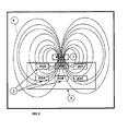
Figure number 2 is a schematic view of the magnet (1) and the sensors (2) in the sensor support (3), as well as a schematic representation of the magnetic field lines (8) that pass through the sensors. -
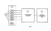
Figure number 3 represents a block diagram which shows the sensors (2) in the sensor support (3), the electronic control (6) and the calculation and signal processing unit (7). -
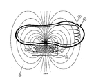
Figure number 4 is a schematic representation of the preferred embodiment of the invention showing the position of a foot (5) in a shoe (4), the sensors (2) in the sensor support (3), fixed to the shoe (4) and the magnet (1) fixed to the part (5) whose relative position with respect to the object (4) is to be ascertained. -
Figure number 4 illustrates a preferred embodiment of the invention. It is intended to ascertain the position and movement of a foot (5) within a shoe (4). - To do this the sensor support (3) which holds six magnetic field sensors (2), three on the same plane and 3 on a different plane is fixed onto a shoe (4) and the magnet (1) is attached to the foot (5) of which the relative position in relation to the object (4) is to be determined.
- The magnet (1) is fixed with an adhesive to the foot (5) or by any other means, for example a sock equipped with a magnet (1) which prevents the magnet from moving (1) with respect to the foot (5); the sensor support (3) is placed within the range of the magnet (1), and the electronic control (4) provides the necessary electrical signals for the processing unit (5) to calculate the relative position of the sensor or sensors (2) with respect to the magnet (1).
- Once the sensor support (3) has been placed within the range of the magnetic field (8) of the magnet (1), a signal will be generated proportional to the magnetic field (8) which is present in the area so that for each relative position of the magnet in relation to the sensor support (3) the sensors (3) will generate a characteristic signal corresponding to each position, and by applying the suitable mathematical algorithm the relation between the relative position of the magnet (1) with respect to the sensor support (3) can be established.
- The sensors (2) transmit this information to the control unit (6) wirelessly, and then from there to the processing unit (7) -again, wirelessly.
- The processing unit (7) translates the relative position of the magnet (1) with respect to the sensor support (3) providing a visualisation of the foot's position (5) with respect to the shoe (4).
- This is a continuous process and lasts the amount of time that was predefined, either in the laboratory, using a treadmill, in which case wireless means for signal transmission are not necessary, or in an open field, which can be carried out due to the use of wireless technology.
- This leads to the generation of information regarding the position of the foot (5) with respect to the shoe (4) in a dynamic environment, that is to say standing (5) and moving, in such a way that the relative position of the foot (5) with regards to the shoe (4) in many diverse conditions and positions of the foot is collected. This would be very valuable information to develop shoes which adapt perfectly to the foot in specific conditions, or which would allow better use of footwear for ergonomic or medical purposes by designing corrective, therapeutic, sports or any other footwear that is adapted for each activity.
- Another preferred embodiment of this invention would consist of detecting the position and movement of the head inside a helmet.
- To do this, the sensor support (3), equipped with corresponding magnetic field sensors (2) would be fixed onto the helmet (4) and the magnet (1) would be placed on the head (5) of which the relative position inside the helmet (4) is to be ascertained.
- The magnet (1) is fixed onto the head (5) using adhesives; the sensor support (3) is placed within the range of the magnet (1), and the electronic control (4) provides the necessary electrical signals for the processing unit (5) to calculate the relative position of the sensors (2) with respect to the magnet (1).
- Once the sensor support (3) has been fixed into place within the magnetic field range (8) of the magnet (1), a signal will be generated which is proportional to the magnetic field (8) which is present in the area so that for each relative position of the magnet in relation to the sensor support (3), the sensors (3) will generate a characteristic signal which corresponds to that position. By then applying a suitable mathematical algorithm it will be possible to establish a relation between the relative position of the magnet (1) in relation to the sensor support (3).
- The sensors (2) transmit this information to the control unit (6) wirelessly, and then from there to the processing unit (7) - again, wirelessly.
- The processor (7) translates the relative position of the magnet (1) in relation to the sensor support (3) allowing a visualisation of the position of the head (5) in relation to the helmet (4).
- This procedure is carried out in a continuous circuit using wireless technology.
- This leads to information about the position of the head (5) with respect to the helmet (4) in a dynamic environment, that is to say: a driver being on a moving vehicle and therefore producing movement in the head (5) with respect to the helmet (4), which would make it possible to know the relative position of the head (5) with respect to the helmet (4) in very diverse driving conditions (acceleration, braking, in curves, etc.), which is very valuable information to develop safer helmets for the driver.
- Likewise, the information can be analysed in test beds, simulating accidents to determine the effects of the impact and the helmet's performance.
- With the position sensor proposed in this invention, different types of footwear, gloves, helmets, saddles, rackets and in general the relative position of whatever object which can at times be completely or partially covered by another object can be compared, for example: glove/hand, head/helmet, plaster cast/arm, observing the real interaction between the objects from the results obtained.
Claims (7)
- Magnetic triangulation based position sensor applicable for determining the relative position of an object or a body part that is hidden or partly or completely covered by another object or material, using sensors which detect the magnetic field generated by a magnet or a set of magnets which are attached to the object in question, characterised by comprising one or more magnets (1); at least three or more magnetic field sensors (2); a sensor support (3); an electronic control unit (6) a processing unit (7) that measures the level of magnetic fields (8) with each sensor (2) and, by applying the adequate mathematical algorithm, can determine the relative position of the magnet (1) placed on the object or part (5) with respect to the object (4) on to which the sensor support (3) has been attached.
- Magnetic triangulation based position sensor, according to the first claim, which is characterised by it establishing a univocal correspondence table between the relative position of the sensor and the magnets, and the electrical signals proportional to the detected magnetic field that they provide, defining each position from the linked magnetic footprint. From such a table the relative position can be established by comparing the magnetic signals detected by the magnetic field sensors and the relative position of the magnets.
- Magnetic triangulation based position sensor: according to the first claim, which is characterised by the magnet or magnets (1) being fixed to the object (5) whose relative position with respect to the other object (4) is to be ascertained using whatever fixing technique that ensures that the magnet (1) and the object (5) move together as one.
- Magnetic triangulation based position sensor, according to the first claim, which is characterised by the magnetic field sensor or sensors (2) being placed on the sensor support (3) which is fixed on the object (4) with respect to which the relative position of another object (5) is to be ascertained, whether it be on the same plane H1A, H1B and H1C or on different planes H2A, H2B and H2C. The sensors may be equipped with data transmission means based on either wireless or non-wireless systems, using radiofrequency or optoelectronics systems.
- Magnetic triangulation based position sensor; according to the first claim, which is characterised by the electronic control unit (6) managing the signals provided by the magnetic field sensors (2), processing, filtering, and AID converting them, and then giving the signals the correct format for the processing unit (7). The sensors may be equipped with data transmission means based on either wireless or non-wireless systems, using radiofrequency or optoelectronics systems.
- Magnetic triangulation based position sensor, according to the first claim, which is characterised by its processing unit (7) comprising a set of electronic circuits which processes the electronic control signals and provides a signal showing the position of the magnet (1) with respect to the sensor support (3) and translates the position into a graphic visualisation of the position of the hidden object (5) with respect to the object or body that hides it (4).
- Magnetic triangulation based position sensor, according to the first claim, which is characterised by the magnetic field sensor or sensors (2) being uniaxial or multiaxial and being sensitive to magnetic fields in one direction or in multiple directions. The magnetic field sensors can be based on whatever technology that is electromagnetic, magnetoresistive or inductive, etc.
Applications Claiming Priority (1)
| Application Number | Priority Date | Filing Date | Title |
|---|---|---|---|
| ES201000095A ES2391970B1 (en) | 2010-01-27 | 2010-01-27 | POSITION SENSOR IN MAGNETIC TRIANGULATION. |
Publications (2)
| Publication Number | Publication Date |
|---|---|
| EP2362189A2 true EP2362189A2 (en) | 2011-08-31 |
| EP2362189A3 EP2362189A3 (en) | 2017-01-11 |
Family
ID=43984005
Family Applications (1)
| Application Number | Title | Priority Date | Filing Date |
|---|---|---|---|
| EP10002725.9A Withdrawn EP2362189A3 (en) | 2010-01-27 | 2010-03-16 | Magnetic triangulation based position sensor |
Country Status (2)
| Country | Link |
|---|---|
| EP (1) | EP2362189A3 (en) |
| ES (1) | ES2391970B1 (en) |
Cited By (5)
| Publication number | Priority date | Publication date | Assignee | Title |
|---|---|---|---|---|
| EP2609394A1 (en) * | 2010-08-27 | 2013-07-03 | Montec Systems Ltd | Improvements to structural separation monitoring systems, methods of installing systems and/or position sensors |
| WO2013138942A1 (en) | 2012-03-23 | 2013-09-26 | Pacific Rim Engineered Products (1987) Ltd. | Gear engagement mechanism for transmissions and related methods |
| US9562758B2 (en) | 2013-04-15 | 2017-02-07 | Stemco Kaiser Incorporated | Distance measurement sensor based on magnetic signal triangulation |
| TWI628527B (en) * | 2017-01-11 | 2018-07-01 | 加銳企業有限公司 | Programmable linear displacement sensing device |
| US10794680B2 (en) | 2016-03-22 | 2020-10-06 | Stemco Products, Inc. | Differential magnetic proximity sensor |
Family Cites Families (7)
| Publication number | Priority date | Publication date | Assignee | Title |
|---|---|---|---|---|
| US4622644A (en) * | 1984-05-10 | 1986-11-11 | Position Orientation Systems, Ltd. | Magnetic position and orientation measurement system |
| US5325869A (en) * | 1991-12-16 | 1994-07-05 | Stokes Theodore J | Apparatus for load and displacement sensing |
| DE29701308U1 (en) * | 1997-01-28 | 1997-05-15 | Schiebl, Frank, Dipl.-Sportlehrer, 71069 Sindelfingen | Movement measuring device for detecting the movement of the foot in the shoe |
| PL369618A1 (en) * | 2004-08-16 | 2006-02-20 | Jakub Mrówka | Method for checking position of the feet inside footwear |
| DE102007036984A1 (en) * | 2007-07-06 | 2009-01-08 | Austriamicrosystems Ag | Measuring method, sensor arrangement and measuring system |
| DE202007018165U1 (en) * | 2007-12-29 | 2009-05-14 | Puma Aktiengesellschaft Rudolf Dassler Sport | Shoe, in particular sports shoe |
| EP2256521A1 (en) * | 2009-05-25 | 2010-12-01 | Fraunhofer-Gesellschaft zur Förderung der angewandten Forschung e.V. | Device and method for magnetic positioning |
-
2010
- 2010-01-27 ES ES201000095A patent/ES2391970B1/en not_active Expired - Fee Related
- 2010-03-16 EP EP10002725.9A patent/EP2362189A3/en not_active Withdrawn
Non-Patent Citations (1)
| Title |
|---|
| None |
Cited By (11)
| Publication number | Priority date | Publication date | Assignee | Title |
|---|---|---|---|---|
| EP2609394A1 (en) * | 2010-08-27 | 2013-07-03 | Montec Systems Ltd | Improvements to structural separation monitoring systems, methods of installing systems and/or position sensors |
| WO2013138942A1 (en) | 2012-03-23 | 2013-09-26 | Pacific Rim Engineered Products (1987) Ltd. | Gear engagement mechanism for transmissions and related methods |
| EP2828621A4 (en) * | 2012-03-23 | 2016-07-20 | Pacific Rim Engineered Products 1987 Ltd | ENGINEERING MECHANISM FOR TRANSMISSIONS AND ASSOCIATED METHODS |
| US9822873B2 (en) | 2012-03-23 | 2017-11-21 | Pacific Rim Engineered Products (1987) Ltd. | Gear engagement mechanism for transmissions and related methods |
| US9562758B2 (en) | 2013-04-15 | 2017-02-07 | Stemco Kaiser Incorporated | Distance measurement sensor based on magnetic signal triangulation |
| US10267615B2 (en) | 2013-04-15 | 2019-04-23 | Stemco Products, Inc. | Distance measurement sensor based on magnetic signal triangulation |
| US11029140B2 (en) | 2013-04-15 | 2021-06-08 | Infinity Engineered Products, Llc | Distance measurement sensor based on magnetic signal triangulation |
| US10794680B2 (en) | 2016-03-22 | 2020-10-06 | Stemco Products, Inc. | Differential magnetic proximity sensor |
| US11326866B2 (en) | 2016-03-22 | 2022-05-10 | Infinity Engineered Products, Llc | Differential magnetic proximity sensor |
| US11573073B2 (en) | 2016-03-22 | 2023-02-07 | Infinity Engineered Products, Llc | Distance measuring devices |
| TWI628527B (en) * | 2017-01-11 | 2018-07-01 | 加銳企業有限公司 | Programmable linear displacement sensing device |
Also Published As
| Publication number | Publication date |
|---|---|
| EP2362189A3 (en) | 2017-01-11 |
| ES2391970A1 (en) | 2012-12-03 |
| ES2391970B1 (en) | 2013-10-16 |
Similar Documents
| Publication | Publication Date | Title |
|---|---|---|
| EP3389498B1 (en) | Fetal monitoring system and method | |
| CN105388495B (en) | Estimating local motion in physical exercise | |
| EP2362189A2 (en) | Magnetic triangulation based position sensor | |
| MejiaCruz et al. | Walking speed measurement technology: a review | |
| KR101578200B1 (en) | Functional game system for balance training and quantitative evaluation | |
| RU2009105666A (en) | HEALTH MANAGEMENT DEVICE | |
| Varela et al. | A kinematic characterization of human walking by using CaTraSys | |
| Anwary et al. | Validity and consistency of concurrent extraction of gait features using inertial measurement units and motion capture system | |
| US20160058373A1 (en) | Running Energy Efficiency | |
| EP1769741A4 (en) | CARDIAC MAGNETIC FIELD DIAGNOSTIC APPARATUS AND THREE DIMENSIONAL LOCALIZATION EVALUATION METHOD FOR DAMAGED CARDIAC MUSCLE | |
| Reenalda et al. | Detection of foot contact in treadmill running with inertial and optical measurement systems | |
| KR101323105B1 (en) | Rehabilitation Treatment Device for Hand and Rehabilitation Method of the Same | |
| KR102539879B1 (en) | Apparatus and method for measuring stiffness of abdomen based on press-fit | |
| Ammann et al. | Human motion component and envelope characterization via wireless wearable sensors | |
| KR20090105785A (en) | Motion Content Based Learning Device and Method | |
| JP2020518296A (en) | Multimodal sensor fusion platform | |
| KR20160105598A (en) | Scanner system using 3D sensor | |
| CN109817056B (en) | Driving behavior data collection device and evaluation device based on vehicle driving | |
| JP2002291723A5 (en) | ||
| JP2018140082A (en) | Measurement system and measurement method | |
| Chebbi et al. | Identifying right and left impact using the derivative of linear resultant acceleration from a single sacrum-mounted IMU | |
| Okmayura et al. | Analysis and design of calories burning calculation in jogging using thresholding based accelerometer sensor | |
| US10573200B2 (en) | System and method for determining a position on an external surface of an object | |
| Pelka et al. | Comparison of concentric movement velocity with push band 2.0 and vicon motion capture during resistance exercises | |
| US20250325877A1 (en) | Method to Identify Right and Left Impact during Running using a Single Sacrum-Mounted IMU |
Legal Events
| Date | Code | Title | Description |
|---|---|---|---|
| PUAI | Public reference made under article 153(3) epc to a published international application that has entered the european phase |
Free format text: ORIGINAL CODE: 0009012 |
|
| AK | Designated contracting states |
Kind code of ref document: A2 Designated state(s): AT BE BG CH CY CZ DE DK EE ES FI FR GB GR HR HU IE IS IT LI LT LU LV MC MK MT NL NO PL PT RO SE SI SK SM TR |
|
| AX | Request for extension of the european patent |
Extension state: AL BA ME RS |
|
| RIN1 | Information on inventor provided before grant (corrected) |
Inventor name: MOREY KLAPSING, GASPAR Inventor name: POVEDA VERDU, DAMIAN Inventor name: ORGILES BARCELO, CESAR Inventor name: ARREGUI DE JUAN-GUTIERREZ, JESUS |
|
| PUAL | Search report despatched |
Free format text: ORIGINAL CODE: 0009013 |
|
| AK | Designated contracting states |
Kind code of ref document: A3 Designated state(s): AT BE BG CH CY CZ DE DK EE ES FI FR GB GR HR HU IE IS IT LI LT LU LV MC MK MT NL NO PL PT RO SE SI SK SM TR |
|
| AX | Request for extension of the european patent |
Extension state: AL BA ME RS |
|
| RIC1 | Information provided on ipc code assigned before grant |
Ipc: G01D 5/14 20060101AFI20161208BHEP |
|
| STAA | Information on the status of an ep patent application or granted ep patent |
Free format text: STATUS: THE APPLICATION IS DEEMED TO BE WITHDRAWN |
|
| 18D | Application deemed to be withdrawn |
Effective date: 20170712 |