EP2362157A1 - Solar collector - Google Patents
Solar collector Download PDFInfo
- Publication number
- EP2362157A1 EP2362157A1 EP10154031A EP10154031A EP2362157A1 EP 2362157 A1 EP2362157 A1 EP 2362157A1 EP 10154031 A EP10154031 A EP 10154031A EP 10154031 A EP10154031 A EP 10154031A EP 2362157 A1 EP2362157 A1 EP 2362157A1
- Authority
- EP
- European Patent Office
- Prior art keywords
- adhesive
- absorber element
- line system
- curing
- line
- Prior art date
- Legal status (The legal status is an assumption and is not a legal conclusion. Google has not performed a legal analysis and makes no representation as to the accuracy of the status listed.)
- Withdrawn
Links
Images
Classifications
-
- F—MECHANICAL ENGINEERING; LIGHTING; HEATING; WEAPONS; BLASTING
- F24—HEATING; RANGES; VENTILATING
- F24S—SOLAR HEAT COLLECTORS; SOLAR HEAT SYSTEMS
- F24S10/00—Solar heat collectors using working fluids
- F24S10/70—Solar heat collectors using working fluids the working fluids being conveyed through tubular absorbing conduits
- F24S10/75—Solar heat collectors using working fluids the working fluids being conveyed through tubular absorbing conduits with enlarged surfaces, e.g. with protrusions or corrugations
-
- F—MECHANICAL ENGINEERING; LIGHTING; HEATING; WEAPONS; BLASTING
- F24—HEATING; RANGES; VENTILATING
- F24S—SOLAR HEAT COLLECTORS; SOLAR HEAT SYSTEMS
- F24S25/00—Arrangement of stationary mountings or supports for solar heat collector modules
- F24S25/60—Fixation means, e.g. fasteners, specially adapted for supporting solar heat collector modules
- F24S2025/601—Fixation means, e.g. fasteners, specially adapted for supporting solar heat collector modules by bonding, e.g. by using adhesives
-
- Y—GENERAL TAGGING OF NEW TECHNOLOGICAL DEVELOPMENTS; GENERAL TAGGING OF CROSS-SECTIONAL TECHNOLOGIES SPANNING OVER SEVERAL SECTIONS OF THE IPC; TECHNICAL SUBJECTS COVERED BY FORMER USPC CROSS-REFERENCE ART COLLECTIONS [XRACs] AND DIGESTS
- Y02—TECHNOLOGIES OR APPLICATIONS FOR MITIGATION OR ADAPTATION AGAINST CLIMATE CHANGE
- Y02E—REDUCTION OF GREENHOUSE GAS [GHG] EMISSIONS, RELATED TO ENERGY GENERATION, TRANSMISSION OR DISTRIBUTION
- Y02E10/00—Energy generation through renewable energy sources
- Y02E10/40—Solar thermal energy, e.g. solar towers
- Y02E10/44—Heat exchange systems
Definitions
- the invention is directed to a method for producing a solar collector comprising an absorber element and a line system.
- the invention is further directed to a solar collector for transmitting radiant energy into a heat transfer medium having a plate-shaped absorber element and a tubular conduit system for the heat transport medium.
- a known solar collector of a first type comprises a photovoltaic module that absorbs solar radiation and provides electrical energy. Such a solar collector for the production of electrical energy in photovoltaic systems is referred to as a solar module.
- a known solar collector of a second type provides heat energy and is referred to as a thermal solar collector. The energy of solar radiation is absorbed in a so-called solar thermal collector with an absorber, converted into heat energy and then delivered to a heat transfer medium, which is guided in thermal contact along the absorber or flows.
- a thermal solar collector converts radiant energy of the sun into heat energy.
- the third type is also known as a photovoltaic thermal collector (PVT collector).
- the heat transferred to the heat transport medium together with the heat transport medium which is present as a fluid (ie liquid or gas), passed through a conduit system in the solar collector and then passed, for example, in a heat storage or immediately as process heat in passed a heat sink.
- the heat can be removed from the heat transport medium in this way via heat exchangers, so that the fluid can be supplied to the solar collector for receiving again.
- the solar radiation accordingly impinges on the absorber element which has been optimized for absorbing radiation, the absorber element additionally being able to be provided with a transparent cover.
- the elements which form the conduit system are thermally coupled to the absorber element.
- Such conduit systems regularly consist of suitable metal alloys, such as copper or aluminum alloys, and are in the form of a meandering or harp-shaped pipeline.
- the conduit system or the pipeline is in thermal contact with the absorber element, so that radiant energy contained in sunlight can be taken up, transferred into the heat transport medium and transported to a heat exchanger.
- the quality of the heat transfer from the absorber element to the heat transport medium is highly dependent on the quality of the connection between the absorber element and the line system.
- Adhesive methods are known from the prior art for connecting the absorber element and the line system. Due to the adhesive present between line system and absorber element, solar collectors with this connection technology have poor heat transfer between the absorber element and the line system. Furthermore, soldering and ultrasonic welding methods are known from the prior art, which have a better heat transfer. A disadvantage of these connection methods, however, is that only absorber elements and piping systems can be connected together from the same materials. Although it is now possible to connect different materials using the ultrasound technology. For this purpose, however, the so-called laser welding connection technology is preferably used today.
- soldering and welding methods have the disadvantage that high temperatures are generated at the connection points between absorber element and the line system, whereby there is a risk that in particular thin-walled absorber elements and / or thin-walled line systems are damaged. There is also the risk that the absorber element and / or the conduit system are permanently and sustainably deformed during the connection due to the influence of temperature and have undesired mechanical stresses after the connection.
- the present invention has for its object to provide a solution that provides a reliable, high-strength and good heat transfer connection between the absorber element and pipe system at the same time simple and inexpensive production.
- a solar collector for collecting and transmitting the radiant energy contained in sunlight in a heat transfer medium having at least one absorber element and a standing in thermal contact with this conduit system for the heat transport medium, wherein the absorber element and the conduit system at least in Surface and / or line contact and an adhesive connection, the absorber element and the conduit system elastically or flexibly interconnects.
- the adhesive bond comprises a non-contact energy input curing two-component adhesive, wherein the solar collector is made by a method according to any one of claims 1 to 8.
- the invention provides a possibility with which a structurally simple manner an elastic connection between the plate-shaped absorber element and tubular conduit system is made.
- the basic idea of the invention is to materially secure the conduit system with a thermosetting adhesive on the absorber element, the connection ensuring that the conduit system is in line and / or surface contact with the absorber element.
- the fact that the line system is in line and / or surface contact with the absorber element, the affects Adhesive bond does not transfer heat between these two components.
- the compound formed in the form of the adhesive bond already after the rapid curing of the adhesive sufficient compressive shear strength, so that the solar collector can be further processed immediately after the rapid curing without relative movement between the absorber element and conduit system will take place.
- the adhesive bond has a sufficient further working strength, ie the adhesive bond is sufficiently stable and shear-resistant for the further processing of the solar collector. Due to the use of an adhesive bond between absorber element and line system, there is no risk that components of the solar collector are damaged during joining. A harmful effect of temperature on the individual components is not given in comparison to soldering and welding. This has a positive effect on their efficiency, especially in the case of solar collectors of the third type (PVT collectors). For example, the selective coating of the absorber element is destroyed or at least attacked by the laser welding, whereby the efficiency of the entire solar collector or PVT collector is reduced.
- the adhesive bond produced by means of the method according to the invention has durability and strength properties which are at least comparable with properties of compounds produced by means of a laser welding process. Overall, compared to soldering or welding technology, the total energy consumption for producing a solar collector is reduced, resulting in a reduction in manufacturing costs. Taking environmental aspects into consideration, the invention has the advantage that the absorber element can be detached from the line system by targeted increased temperature introduction into the adhesive connection, so that both components can be supplied to a recycling process, should the solar collector have reached the end of its life or operating time ,
- the invention provides that for curing of the adhesive, the absorber element and the conduit system are introduced into a space separable from the environment, the room is separated from the environment, the temperature in the interior of the room to 60 ° C to 120 ° C is increased and the adhesive is cured or cured at this temperature for 60 to 120 seconds.
- the adhesive cures and thus the adhesive bond between absorber element and conduit system within a very short time and achieves a further processing strength, which is characterized in that under the influence of normal forces, the absorber element and the conduit system can not be moved relative to each other.
- the adhesive bond has a peel strength of about 200 N after this short period of time, ie absorber element and line system hold when pulling a force of about 200 N stood.
- the adhesive for curing of the adhesive, is selectively exposed by means of an infrared radiation, in particular a near-infrared radiation.
- the adhesive is exposed at a certain angle by means of an infrared light source for a certain time, for example 75 to 180 seconds, in order to achieve sufficient curing and strength of the adhesive bond for further processing of the solar collector.
- the invention provides in an alternative embodiment of the method that the curing of the adhesive takes place at room temperature.
- a large amount of space is required for the mass production of solar collectors in this type of curing, because the required further processing strength of the adhesive bond is achieved only after 10 to 90 minutes, so that the bonded components must first be stored for curing.
- a two-component silicone adhesive is used as an adhesive.
- a two-component silicone adhesive for example, PACTAN 8071 in a mixing ratio of 1: 1 or Novosil VP 6431 from OTTO Chemie in a mixing ratio of 100: 14 come into consideration.
- These two-component silicone adhesives are characterized by the fact that their processing viscosity is pasty.
- both adhesives have good thermal conductivity and exceptionally high adhesion properties over a high temperature range, being UV resistant and degassing free after rapid cure.
- such two-component silicone adhesive are characterized by a low hardness and high elongation at break.
- two-component silicone adhesives can be used wherever materials with different coefficients of expansion need to be bonded. It should be noted that with one-component adhesives, which have, for example, epoxides, high wear of the metering pumps and metering valves must be expected. This disadvantage does not exist in the inventively provided two-component silicone adhesive.
- the invention provides that, prior to the application of the adhesive, the regions to be joined are cleaned by the absorber element and the line system, preferably by means of a plasma process or plasma plus process.
- a plasma process there are hardly any restrictions on the material to be cleaned so that temperature-sensitive plastics as well as metal, glass and ceramics can be treated.
- a layer is additionally applied, which improves the adhesion desired in the further course of the process.
- the plasma process and the plasma plus process must be adapted to the particular task and the material in any case.
- a solar collector usually serves to collect and transfer the radiant energy contained in sunlight into a heat transport medium.
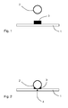
- a solar collector is fragmentary and schematic in the Figures 1 and 2 illustrated and comprises at least one plate-shaped absorber element 1, which may be selectively coated and made of metal, and standing with this in thermal contact, tubular conduit system 2 for the heat transport medium.
- the term absorber element is understood to mean both a plate-shaped element and narrow metal strips (so-called absorber fins) which are connected to the line system 2.
- the conduit system 2 is a meandering or harp-shaped pipe, wherein other configurations and shapes of the conduit system 2 are conceivable.
- the use of cross-section polygonal pipes instead of circular cross-sections is conceivable.
- the absorber element 1 and the conduit system 2 are connected to one another according to the invention by means of an adhesive 3 forming an adhesive bond.
- an adhesive 3 since almost every surface is contaminated during various operations in the manufacturing process, the surfaces of the components should or should be cleaned, for example, before applying the adhesive, ie before further operations.
- a plasma cleaning is a way to get absolutely clean, grease-free surfaces.
- the regions to be joined are cleaned, for example by means of a plasma process, which, among other things, degreases the surfaces to a high degree.
- plasma cleaning there are hardly any restrictions with regard to the material / material to be cleaned.
- temperature-sensitive plastics can be treated as well as metal, glass and ceramics.
- the plasma process must be adapted to the respective task in any case.
- a chemical pretreatment may be used to clean the areas to be joined, such as solvent vapor removal.
- an adhesion promoter to the regions of the absorber element 1 and / or the line system 2 to be connected. This is always necessary when different materials have to be glued together or when a particular adhesive is to be used because of its special properties, but the adhesive does not adhere sufficiently well on one of the two adhesive partners.
- the multi-component adhesive 3 is applied to the regions of the absorber element 1 to be joined.
- the application is preferably carried out automatically.
- a two-component silicone adhesive is used as the adhesive 3, which has a good thermal conductivity and exceptionally high adhesion properties over a high temperature range.
- this adhesive 3 is UV-resistant and degassing after rapid curing.
- PACTAN 8071 and Novosil VP 6431 from OTTO Chemie are mentioned here.
- the two components (adhesive and hardener) of the adhesive 3 are in liquid to pasty form and must be mixed together before application in a certain mixing ratio, the mixing ratio of adhesive and hardener usually between 100: 15 to 100: 30 parts by weight, in Individual cases even with 1: 1 volume fractions.
- PACTAN 8071 is used in a mixing ratio of 1: 1 and Novosil VP 6431 in a mixing ratio of 100: 14.
- the mixing of the two components and the subsequent application of the two-component silicone adhesive takes place in a fully automated Process step, wherein, for example, a static, static-dynamic or dynamic mixing unit with metering pump and mixing head, the adhesive 3 in a predetermined amount and in a predetermined mixing ratio on the absorber element 1 or on the line system 2 or both on absorber element 1 and 2 line system applies.
- a static, static-dynamic or dynamic mixing unit with metering pump and mixing head the adhesive 3 in a predetermined amount and in a predetermined mixing ratio on the absorber element 1 or on the line system 2 or both on absorber element 1 and 2 line system applies.
- the components of the solar collector to be connected ie the absorber element 1 and the line system 2 are arranged or positioned in their assembly position.
- the absorber element 1 is held or fixed by means of a vacuum clamping table, which, however, can take place even before the application of the adhesive 3.
- the line system 2 is then transported, for example as part of an automated method step, by a robot unit to the absorber element 1 fixed on the vacuum table.
- the absorber element 1 and the conduit system 2 are then temporarily releasably fixed, for example, by means of clips or other mechanical fastening means. In this case, the arrangement or joining of the two parts to one another can take place in an automated method step.
- This automated step comprises that the conduit system 2 and the absorber element 1 are pressed against each other such that the conduit system rests directly on the absorber element and is in complete thermal contact with it both in line contact 4 as well.
- This arrangement of both components, in which they are in line contact 4 corresponds to the assembly position.
- fastening means can then be manually or automatically attached to the arrangement and releasable fixing of the absorber element 1 and the conduit system 2 in the assembly position, so that a partially automated process step is present.
- the curing of the adhesive bond ie up to a sufficient strength for further processing ability, remain Absorber element 1 and the conduit system 2 fixed, with a low fixing pressure is sufficient.
- the curing of the adhesive 3 by means of contactless energy is introduced into the adhesive 3, so that after curing, the absorber element 1 and the line system 2 are in line contact 4 and by means of the line contact 4 arranged adhesive 3 (see FIG. 2 ).
- the line contact 4 is a portion of the outer wall of the circular cross-section conduit system 2 directly and without gaps on the absorber element 1. In, for example, quadrangular piping systems, there would be a surface contact between the outer wall of the piping system and the absorber element 1.
- the absorber element 1 and the line system 2 are introduced into a space which is separable from the environment for hardening the adhesive.
- This space is adapted to the outer dimensions of the components to be connected and has a plurality of hot air nozzles, can be directed by a hot or heated air flow directly and selectively to the multi-component adhesive 3 and the adhesive bond.
- the room is separated from the environment, with the total temperature inside the room rising to 60 ° C to 120 ° C.
- the nozzles are directed to the adhesive bond or only hot air nozzles are applied, whose air flow meets the adhesive bond.
- the multi-component adhesive 3 then cures at a temperature between 60 ° C and 120 ° C. There is a temperature monitoring by means of suitable sensors, so that it is ensured that the adhesive 3 or the silicone compound is not damaged.
- the contactless introduction of energy into the multicomponent adhesive 3 causes an accelerated reaction of the silicone composition and favors a fast curing or rapid curing of the multi-component adhesive 3, so that in a relatively short time the adhesive bond between the absorber element 1 and conduit system 2 has a minimum strength or further processing strength.
- An alternative method step for non-contact introduction of energy into the multi-component adhesive 3 can take place via the line system without introduction of the components to be connected in a space separated from the environment.
- heat is transferred via the conduit system by means of generating a flow of current in the conduit system to the adhesive for curing of the adhesive 3, wherein after a cycle time of about 80 to 180 seconds, a sufficient further processing strength is achieved.
- a required further processing strength is achieved after a cycle time of about 75 to 180 seconds.
- the adhesive bond between absorber element 1 and line system 2 can also cure at room temperature, in which case the required further processing stability is achieved after a cycle time of approximately 10 to 90 minutes.
- a specially provided step of cooling is not required in this type of adhesive bonding by means of the multi-component adhesive 3 due to the accelerated curing reaction.
- the holding devices and previously attached mechanical fixing devices can then be loosened and / or removed before the absorber element 1 and the line system 2 connected thereto are supplied with further processing steps.
- the absorber element 1 and the conduit system 2 are after rapid curing by means of the adhesive connection in the case of the circular tube-shaped conduit system 2 in line contact 4, ie a portion of the outer wall of the conduit system 2 is directly and without gaps on the absorber element 1.
- the two-component adhesive comprising contact-free energy input curing adhesive bond connects the absorber element 1 and the conduit system 2 elastically together, so that material expansion of absorber element 1 and / or conduit system 2 can be compensated due to strong temperature changes by the elastic adhesive bond.
- This adhesive connection ensures a uniform distribution of stress over the entire joining region of absorber element 1 and line system 2 and the compensation of different coefficients of expansion of absorber element 1 and line system 2.
- solar collectors with an adhesive bond between the absorber element and the line system can be created, which have a comparable or better efficiency with welded absorbers and at the same time lower production costs.
- the invention also has the advantage that this compound is not subject to mechanical voltage changes (for example, due to strong temperature changes), but rather the elastic or flexible adhesive connection always the line contact 4 of the absorber element and the line system, which is important for the efficiency of the solar collector guaranteed.
- this compound is not subject to mechanical voltage changes (for example, due to strong temperature changes), but rather the elastic or flexible adhesive connection always the line contact 4 of the absorber element and the line system, which is important for the efficiency of the solar collector guaranteed.
- the multicomponent adhesive decomposes into its components (for example silicon) and the adhesive bond between the absorber element and the line system is released.
- the invention has advantages over a laser welding process, because the compounds of the laser welding are alloys that solve it consuming and then to dispose of.
- the components of the solar collector according to the invention can be reused.
- the method described above is not only suitable for connecting an absorber element and a line system with one another.
- the adhesive bond with rapid curing is also suitable to realize other connections of the solar collector, such as the connection of the collector frame and glass cover or collector frame and rear wall, with high reliability, the method of the invention can be adapted for such compounds to the cycle times of series production ,
Abstract
Description
Die Erfindung richtet sich auf ein Verfahren zur Herstellung eines ein Absorberelement und ein Leitungssystem umfassenden Solarkollektors. Die Erfindung richtet sich ferner auf einen Solarkollektor zum Übertragen von Strahlungsenergie in ein Wärmetransportmedium, der ein plattenförmig ausgebildetes Absorberelement und ein rohrförmig ausgebildetes Leitungssystem für das Wärmetransportmedium aufweist.The invention is directed to a method for producing a solar collector comprising an absorber element and a line system. The invention is further directed to a solar collector for transmitting radiant energy into a heat transfer medium having a plate-shaped absorber element and a tubular conduit system for the heat transport medium.
Solarkollektoren oder Sonnenkollektoren sind in vielfältiger Gestaltung aus dem Stand der Technik bekannt und bezeichnen Vorrichtungen zur Sammlung der im Sonnenlicht enthaltenen Energie. Ein bekannter Solarkollektor einer ersten Bauart umfasst ein photovoltaisches Modul, das Sonnenstrahlung absorbiert und elektrische Energie liefert. Ein solcher Solarkollektor zur Gewinnung von elektrischer Energie in Photovoltaikanlagen wird als Solarmodul bezeichnet. Ein bekannter Solarkollektor einer zweiten Bauart liefert Wärmeenergie und wird als thermischer Solarkollektor bezeichnet. Die Energie der Sonnenstrahlung wird bei einem sogenannten thermischen Solarkollektor mit einem Absorber aufgenommen, in Wärmeenergie gewandelt und anschließend an ein Wärmetransportmedium abgegeben, das in thermischen Kontakt an dem Absorber entlang geführt wird oder fließt. Im Gegensatz zu einem Photovoltaik- bzw. Solarmodul, welches die Sonnenenergie in elektrische Energie umwandelt, wandelt ein thermischer Solarkollektor Strahlungsenergie der Sonne in Wärmeenergie um. Darüber hinaus existiert heutzutage eine dritte Bauart von Solarkollektoren, bei denen die Technologien der ersten und zweiten Bauart vereint sind, d.h. solche Solarkollektoren dienen sowohl der Wärme- als auch der Stormerzeugung. Die dritte Bauart wird auch als photovoltaischer thermischer Kollektor bezeichnet (PVT-Kollektor).Solar collectors or solar panels are known in various designs from the prior art and indicate devices for collecting the energy contained in sunlight. A known solar collector of a first type comprises a photovoltaic module that absorbs solar radiation and provides electrical energy. Such a solar collector for the production of electrical energy in photovoltaic systems is referred to as a solar module. A known solar collector of a second type provides heat energy and is referred to as a thermal solar collector. The energy of solar radiation is absorbed in a so-called solar thermal collector with an absorber, converted into heat energy and then delivered to a heat transfer medium, which is guided in thermal contact along the absorber or flows. In contrast to a photovoltaic or solar module, which converts solar energy into electrical energy, a thermal solar collector converts radiant energy of the sun into heat energy. In addition, there is now a third type of solar collectors, in which the technologies of the first and second type are combined, ie, such solar collectors are used both the heat and the generation of electricity. The third type is also known as a photovoltaic thermal collector (PVT collector).
Bei den Solarkollektoren der zweiten und dritten Bauart wird die an das Wärmetransportmedium übertragene Wärme zusammen mit dem Wärmetransportmedium, welches als Fluid (also Flüssigkeit oder Gas) vorliegt, durch ein Leitungssystem in dem Solarkollektor geführt und dann beispielsweise in einen Wärmespeicher geleitet oder sofort als Prozesswärme in eine Wärmesenke geleitet. Die Wärme kann dem Wärmetransportmedium auf diesem Weg über Wärmetauscher entzogen werden, so dass das Fluid wieder zur Aufnahme dem Solarkollektor zugeführt werden kann.In the solar collectors of the second and third type, the heat transferred to the heat transport medium together with the heat transport medium, which is present as a fluid (ie liquid or gas), passed through a conduit system in the solar collector and then passed, for example, in a heat storage or immediately as process heat in passed a heat sink. The heat can be removed from the heat transport medium in this way via heat exchangers, so that the fluid can be supplied to the solar collector for receiving again.
Bei Solarkollektoren trifft die Sonnenstrahlung demnach auf das zur Strahlungsabsorption optimierte Absorberelement auf, wobei das Absorberelement dabei zusätzlich mit einer transparenten Abdeckung versehen sein kann. Die Elemente, welche das Leitungssystem bilden, sind thermisch mit dem Absorberelement gekoppelt. Derartige Leitungssysteme bestehen regelmäßig aus geeigneten Metalllegierungen, wie beispielweise Kupfer- oder Aluminiumlegierungen, und sind in Form einer mäanderförmigen oder harfenförmigen Rohrleitung ausgebildet.In the case of solar collectors, the solar radiation accordingly impinges on the absorber element which has been optimized for absorbing radiation, the absorber element additionally being able to be provided with a transparent cover. The elements which form the conduit system are thermally coupled to the absorber element. Such conduit systems regularly consist of suitable metal alloys, such as copper or aluminum alloys, and are in the form of a meandering or harp-shaped pipeline.
Das Leitungssystem bzw. die Rohrleitung steht in thermischem Kontakt mit dem Absorberelement, so dass im Sonnenlicht enthaltene Strahlungsenergie aufgenommen, in das Wärmetransportmedium übertragen und zu einem Wärmetauscher transportiert werden kann. Die Qualität der Wärmeübertragung von Absorberelement auf das Wärmetransportmedium ist stark von der Güte der Verbindung von Absorberelement und Leitungssystem abhängig.The conduit system or the pipeline is in thermal contact with the absorber element, so that radiant energy contained in sunlight can be taken up, transferred into the heat transport medium and transported to a heat exchanger. The quality of the heat transfer from the absorber element to the heat transport medium is highly dependent on the quality of the connection between the absorber element and the line system.
Zur Verbindung von Absorberelement und Leitungssystem sind aus dem Stand der Technik Klebeverfahren bekannt. Aufgrund des zwischen Leitungssystem und Absorberelement vorhandenen Klebemittels weisen Solarkollektoren mit dieser Verbindungstechnologie eine schlechte Wärmeübertragung zwischen dem Absorberelement und dem Leitungssystem auf. Ferner sind aus dem Stand der Technik Löt- und Ultraschallschweißverfahren bekannt, die einen besseren Wärmeübergang aufweisen. Nachteilig bei diesen Verbindungsverfahren ist jedoch, dass nur Absorberelemente und Leitungssysteme aus gleichen Werkstoffen miteinander verbunden werden können. Zwar ist es heutzutage möglich, mittels der Ultraschweißtechnologie auch unterschiedliche Werkstoffe miteinander zu verbinden. Zu diesem Zweck wird jedoch heutzutage bevorzugt die sogenannte Laserschweiß-Verbindungstechnologie eingesetzt. Die vorstehend genannten Löt- und Schweißverfahren weisen jedoch den Nachteil auf, dass hohe Temperaturen an den Verbindungsstellen zwischen Absorberelement und dem Leitungssystem erzeugt werden, wodurch die Gefahr besteht, dass insbesondere dünnwandige Absorberelemente und/oder dünnwandige Leitungssysteme beschädigt werden. Auch besteht die Gefahr, dass beim Verbinden aufgrund des Temperatureinflusses das Absorberelement und/oder das Leitungssystem dauerhaft und nachhaltig verformt werden und nach dem Verbinden unerwünschte mechanische Spannungen aufweisen.Adhesive methods are known from the prior art for connecting the absorber element and the line system. Due to the adhesive present between line system and absorber element, solar collectors with this connection technology have poor heat transfer between the absorber element and the line system. Furthermore, soldering and ultrasonic welding methods are known from the prior art, which have a better heat transfer. A disadvantage of these connection methods, however, is that only absorber elements and piping systems can be connected together from the same materials. Although it is now possible to connect different materials using the ultrasound technology. For this purpose, however, the so-called laser welding connection technology is preferably used today. However, the abovementioned soldering and welding methods have the disadvantage that high temperatures are generated at the connection points between absorber element and the line system, whereby there is a risk that in particular thin-walled absorber elements and / or thin-walled line systems are damaged. There is also the risk that the absorber element and / or the conduit system are permanently and sustainably deformed during the connection due to the influence of temperature and have undesired mechanical stresses after the connection.
Darüber hinaus stellen die Schweißverfahren aus energietechnischer und wirtschaftlicher Sicht recht teure und aufwendige Verbindungsverfahren dar. Das zeitaufwendige Verschweißen von Absorberelement und Leitungssystem erhöht die Taktzeiten der Serienfertigung, da alle sonstigen Herstellungsschritte eines Solarkollektors zügiger abgearbeitet werden.In addition, the welding processes from a power engineering and economic point of view are quite expensive and expensive connection methods. The time-consuming welding of absorber element and pipe system increases the cycle times of series production, as all other manufacturing steps of a solar collector are processed more quickly.
Der vorliegenden Erfindung liegt die Aufgabe zugrunde, eine Lösung zu schaffen, die eine zuverlässige, hochfeste und einen guten Wärmeübergang aufweisende Verbindung zwischen Absorberelement und Leitungssystem bei gleichzeitig einfacher und kostengünstiger Herstellung bereitstellt.The present invention has for its object to provide a solution that provides a reliable, high-strength and good heat transfer connection between the absorber element and pipe system at the same time simple and inexpensive production.
Diese Aufgabe wird erfindungsgemäß gelöst durch ein Verfahren zur Herstellung eines ein Absorberelement und ein Leitungssystem umfassenden Solarkollektors, wobei das erfindungsgemäße Verfahren die Schritte aufweist:
- ● Auftragen eines mehrkomponentigen Klebemittels auf zu verbindende Bereiche des Absorberelements und/oder des Leitungssystems mittels eines Mischkopfes,
- ● Anordnen des Absorberelements und des Leitungssystems in ihrer Zusammenbauposition derart, dass das Leitungssystem auf dem Absorberelement aufliegt und mit diesem in thermischem Kontakt steht, und
- ● Aushärten des Klebemittels mittels berührungslosen Einbringens von Energie in das Klebemittel, so dass nach dem Aushärten das Absorberelement und das Leitungssystem wenigstens in Flächen- und/oder Linienberührung stehen und mittels des neben der Flächen- und/oder Linienberührung angeordneten Klebemittels miteinander verbunden werden.
- Application of a multicomponent adhesive to regions of the absorber element and / or the conduit system to be connected by means of a mixing head,
- ● arranging the absorber element and the conduit system in their assembly position such that the conduit system rests on the absorber element and is in thermal contact with this, and
- ● curing of the adhesive by means of non-contact introduction of energy into the adhesive, so that after curing, the absorber element and the conduit system at least in area and / or line contact and are connected to each other by means of the arranged next to the surface and / or line contact adhesive.
Die vorstehend genannte Aufgabe wird erfindungsgemäß ebenso gelöst durch einen Solarkollektor zur Sammlung und Übertragung der im Sonnenlicht enthaltenen Strahlungsenergie in ein Wärmetransportmedium, der wenigstens ein Absorberelement und ein mit diesem in thermischen Kontakt stehendes Leitungssystem für das Wärmetransportmedium aufweist, wobei das Absorberelement und das Leitungssystem wenigstens in Flächen- und/oder Linienberührung stehen und eine Klebeverbindung das Absorberelement und das Leitungssystem elastisch bzw. flexibel miteinander verbindet. Die Klebeverbindung umfasst ein unter berührungsloser Energieeinbringung aushärtendes Zwei-Komponenten-Klebemittel, wobei der Solarkollektor mittels eines Verfahrens nach einem der Ansprüche 1 bis 8 hergestellt ist.The above object is also achieved by a solar collector for collecting and transmitting the radiant energy contained in sunlight in a heat transfer medium having at least one absorber element and a standing in thermal contact with this conduit system for the heat transport medium, wherein the absorber element and the conduit system at least in Surface and / or line contact and an adhesive connection, the absorber element and the conduit system elastically or flexibly interconnects. The adhesive bond comprises a non-contact energy input curing two-component adhesive, wherein the solar collector is made by a method according to any one of
Vorteilhafte und zweckmäßige Ausgestaltungen und Weiterbildungen der Erfindung ergeben sich aus den entsprechenden Unteransprüchen.Advantageous and expedient refinements and developments of the invention will become apparent from the corresponding dependent claims.
Durch die Erfindung wird eine Möglichkeit bereitgestellt, mit welcher auf konstruktiv einfache Weise eine elastische Verbindung zwischen dem plattenförmigen Absorberelement und rohrförmigen Leitungssystem hergestellt wird. Der Grundgedanke der Erfindung besteht darin, das Leitungssystem mit einem wärmehärtenden Klebemittel auf dem Absorberelement stoffschlüssig zu befestigen, wobei die Verbindung gewährleistet, dass das Leitungssystem in Linien- und/oder Flächenberührung zu dem Absorberelement steht. Dadurch, dass das Leitungssystem in Linien- und/oder Flächenberührung mit dem Absorberelement steht, beeinflusst die Klebeverbindung nicht die Wärmeübertragung zwischen diesen beiden Bauteilen. Ferner weist die in Form der Klebeverbindung ausgebildete Verbindung bereits nach der Schnellaushärtung des Klebemittels eine ausreichende Druckscherfestigkeit auf, so dass der Solarkollektor unmittelbar nach der Schnellaushärtung weiter verarbeitet werden kann, ohne dass zwischen Absorberelement und Leitungssystem eine Relativbewegung stattfinden wird. In diesem Zusammenhang spricht man auch davon, dass die Klebeverbindung eine ausreichende Weiterbearbeitungsfestigkeit aufweist, d.h. die Klebeverbindung ist ausreichend stabil und scherfest für die Weiterbearbeitung des Solarkollektors. Aufgrund der Verwendung einer Klebeverbindung zwischen Absorberelement und Leitungssystem besteht keine Gefahr, dass Bauteile des Solarkollektors beim Fügen beschädigt werden. Eine schädliche Temperatureinwirkung auf die einzelnen Bauteile ist im Vergleich zum Löten und Schweißen nicht gegeben. Dies wirkt sich insbesondere bei Solarkollektoren der dritten Bauart (PVT-Kollektoren) positiv auf deren Wirkungsgrad aus. Beispielsweise wird durch das Laserschweißen die selektive Beschichtung des Absorberelements zerstört bzw. zumindest angegriffen, wodurch sich der Wirkungsgrad des gesamten Solarkollektors bzw. PVT-Kollektors verringert. Ein derartig nachteiliger Einfluss auf die selektive Beschichtung des Absorberelements wird aber gerade bei dem erfindungsgemäßen Verfahren vermieden, so dass insbesondere bei einem PVT-Kollektor mittels der Erfindung ein höherer Wirkungsgrad im Vergleich zum Laserschweißverfahren erzielt wird. Auch wirkt sich der durch das Verfahren vermiedene Temperatureinfluss auf die Verwendung von dünnwandigen Bauteilen positiv aus, bei denen es im Rahmen von Schweißverfahren immer wieder zu Beschädigungen der Bauteile infolge der dünnen Wandstärke kommt und die Bauteile aus diesem Grund mit einer höheren Materialstärke ausgebildet sind. Eine solche Überdimensionierung hinsichtlich der Materialstärke ist bei dem erfindungsgemäßen Verfahren nicht erforderlich, so dass eine Nutzung des erfindungsgemäßen Verfahrens auch eine gewisse Materialeinsparung nach sich zieht, wodurch die Herstellkosten eines Solarkollektors weiter gesenkt werden. Zudem wird durch das erfindungsgemäße Verfahren aufgrund der elastischen Verbindung ein Verzug der verbunden Bauteile ausgeschlossen, so dass beispielsweise das mit dem Leitungssystem verbundene Absorberelement ohne Überschreitung einzuhaltender Einbautoleranzen problemlos in einen Rahmen des Solarkollektors eingesetzt und eingebaut werden kann und keine Nachbearbeitung hinsichtlich etwaiger Kollektoranschlüsse erforderlich sind. Auch ist es nun mit Hilfe des erfindungsgemäßen Verfahrens möglich, unterschiedliche Werkstoffpaarungen für Absorberelement und Leitungssystem (beispielsweise eine Kombination von Stahlblech und Alurohrsystem) zu verwenden. Eine diesbezügliche Einschränkung besteht nicht. Darüber hinaus ist es aufgrund des erfindungsgemäßen Verfahrens in Verbindung mit der Schnellaushärtung möglich, auch dreidimensionale Konturen oder Körper herzustellen, was mittels der bekannten Schweißverfahren generell nicht möglich ist. Die mittels des erfindungsgemäßen Verfahrens hergestellte Klebeverbindung weist Haltbarkeits- und Festigkeitseigenschaften auf, die mit Eigenschaften von mittels eines Laserschweißverfahrens hergestellten Verbindungen zumindest vergleichbar sind. Insgesamt verringert sich im Vergleich zur Löt- oder Schweißtechnologie der Gesamtenergieverbrauch zur Herstellung eines Solarkollektors, was eine Reduzierung der Herstellkosten nach sich zieht. Unter Berücksichtigung umweltrelevanter Aspekte weist die Erfindung den Vorteil auf, dass durch gezielte erhöhte Temperatureinbringung in die Klebeverbindung das Absorberelement von dem Leitungssystem gelöst werden kann, so dass beide Bauteile einem Wiederverwertungsprozess zugeführt werden können, sollte der Solarkollektor das Ende seiner Lebens- oder Betriebszeit erreicht haben.The invention provides a possibility with which a structurally simple manner an elastic connection between the plate-shaped absorber element and tubular conduit system is made. The basic idea of the invention is to materially secure the conduit system with a thermosetting adhesive on the absorber element, the connection ensuring that the conduit system is in line and / or surface contact with the absorber element. The fact that the line system is in line and / or surface contact with the absorber element, the affects Adhesive bond does not transfer heat between these two components. Furthermore, the compound formed in the form of the adhesive bond already after the rapid curing of the adhesive sufficient compressive shear strength, so that the solar collector can be further processed immediately after the rapid curing without relative movement between the absorber element and conduit system will take place. In this context, one also speaks of the fact that the adhesive bond has a sufficient further working strength, ie the adhesive bond is sufficiently stable and shear-resistant for the further processing of the solar collector. Due to the use of an adhesive bond between absorber element and line system, there is no risk that components of the solar collector are damaged during joining. A harmful effect of temperature on the individual components is not given in comparison to soldering and welding. This has a positive effect on their efficiency, especially in the case of solar collectors of the third type (PVT collectors). For example, the selective coating of the absorber element is destroyed or at least attacked by the laser welding, whereby the efficiency of the entire solar collector or PVT collector is reduced. However, such a disadvantageous influence on the selective coating of the absorber element is avoided precisely in the method according to the invention, so that a higher efficiency is achieved in comparison with the laser welding method, in particular with a PVT collector by means of the invention. Also, the temperature influence avoided by the method has a positive effect on the use of thin-walled components, in which welding components repeatedly cause damage to the components as a result of the thin wall thickness and for this reason the components are formed with a higher material thickness. Such oversizing with respect to the material thickness is not required in the method according to the invention, so that use of the method according to the invention also entails a certain saving of material, whereby the production costs of a solar collector are further reduced. In addition, by the inventive method due to the elastic Connection a delay of the connected components excluded so that, for example, connected to the conduit system absorber element can be easily used and installed without exceeding the installation tolerances in a frame of the solar collector and no post-processing with regard to any collector connections are required. Also, it is now possible with the help of the method according to the invention to use different material pairings for absorber element and pipe system (for example, a combination of steel sheet and Alurohrsystem). There is no such restriction. In addition, it is possible due to the method according to the invention in connection with the rapid curing, also to produce three-dimensional contours or body, which is generally not possible by means of the known welding methods. The adhesive bond produced by means of the method according to the invention has durability and strength properties which are at least comparable with properties of compounds produced by means of a laser welding process. Overall, compared to soldering or welding technology, the total energy consumption for producing a solar collector is reduced, resulting in a reduction in manufacturing costs. Taking environmental aspects into consideration, the invention has the advantage that the absorber element can be detached from the line system by targeted increased temperature introduction into the adhesive connection, so that both components can be supplied to a recycling process, should the solar collector have reached the end of its life or operating time ,
In Ausgestaltung des Verfahrens sieht die Erfindung vor, dass zum Aushärten des Klebemittels das Absorberelement und das Leitungssystem in einen von der Umgebung separierbaren Raum eingebracht werden, der Raum von der Umgebung separiert wird, die Temperatur im Inneren des Raumes auf 60°C bis 120°C erhöht wird und das Klebemittel bei dieser Temperatur für 60 bis 120 Sekunden ausgehärtet wird bzw. aushärtet. Durch diesen Verfahrensschritt härtet das Klebemittel und damit die Klebeverbindung zwischen Absorberelement und Leitungssystem innerhalb kürzester Zeit aus und erreicht eine Weiterbearbeitungsfestigkeit, die sich dadurch auszeichnet, dass unter dem Einfluss normaler Kräfte das Absorberelement und das Leitungssystem nicht mehr relativ zueinander bewegt werden können. Die Klebeverbindung weist nach dieser kurzen Zeitspanne eine Abzugsfestigkeit von ca. 200 N auf, d.h. Absorberelement und Leitungssystem halten beim Auseinanderziehen einer Kraft von etwa 200 N stand. Darüber hinaus sind während dieser Zeitspanne, d.h. nach der Schnellaushärtung, sämtliche Ausgasungsvorgänge des Klebemittels abgeschlossen. Im Vergleich zum Laserschweißverfahren, welches zur Verbindung von Absorberelement und Leitungssystem in etwa 140 Sekunden benötigt, wird durch das erfindungsgemäße Verbindungsverfahren ein im Wirkungsgrad vergleichbarer Solarkollektor geschaffen, so dass unter wirtschaftlichen Gesichtspunkten die Klebeverbindung einen Vorteil gegenüber den bekannten Schweiß-Technologien aufweist.In an embodiment of the method, the invention provides that for curing of the adhesive, the absorber element and the conduit system are introduced into a space separable from the environment, the room is separated from the environment, the temperature in the interior of the room to 60 ° C to 120 ° C is increased and the adhesive is cured or cured at this temperature for 60 to 120 seconds. By this process step, the adhesive cures and thus the adhesive bond between absorber element and conduit system within a very short time and achieves a further processing strength, which is characterized in that under the influence of normal forces, the absorber element and the conduit system can not be moved relative to each other. The adhesive bond has a peel strength of about 200 N after this short period of time, ie absorber element and line system hold when pulling a force of about 200 N stood. In addition, during this period, ie after rapid curing, all outgassing of the adhesive is completed. Compared to the laser welding process, which requires the connection of absorber element and line system in about 140 seconds, is provided by the inventive compound method in a comparable efficiency solar collector, so that from an economic point of view, the adhesive connection has an advantage over the known welding technologies.
Eine alternative Art des berührungslosen Einbringens von Energie in das Klebemittel ist in erfindungsgemäßer Weiterbildung des Verfahrens dadurch vorgesehen, dass zum Aushärten des Klebemittels Wärme über das Leitungssystem mittels erzeugen eines Stromflusses in dem Leitungssystem auf das Klebemittel übertragen wird. Eine ausreichende Weiterbearbeitungsfestigkeit wird hierbei nach ca. 90 bis 180 Sekunden erreicht, wobei jedoch das Anlegen der Spannung sehr sorgsam erfolgen muss, um das Leitungssystem und damit das Klebemittel einheitlich zu erwärmen.An alternative type of non-contact introduction of energy into the adhesive is provided in the invention development of the method, that is transferred to the curing of the adhesive heat via the conduit system by generating a current flow in the conduit system to the adhesive. A sufficient further processing strength is achieved after about 90 to 180 seconds, but the application of the voltage must be very carefully to heat the pipe system and thus the adhesive uniformly.
In alternativer Ausgestaltung des erfindungsgemäßen Verfahrens ist vorgesehen, dass zum Aushärten des Klebemittels das Klebemittel gezielt mittels einer Infrarot-Strahlung, insbesondere einer Nahinfrarot-Strahlung, belichtet wird. Dabei wird das Klebemittel unter einem bestimmten Winkel mittels einer Infrarot-Lichtquelle für eine gewisse Zeit, beispielsweise 75 bis 180 Sekunden, belichtet, um eine ausreichende Aushärtung und Festigkeit der Klebeverbindung zur Weiterbearbeitung des Solarkollektors zu erzielen.In an alternative embodiment of the method according to the invention it is provided that for curing of the adhesive, the adhesive is selectively exposed by means of an infrared radiation, in particular a near-infrared radiation. In this case, the adhesive is exposed at a certain angle by means of an infrared light source for a certain time, for example 75 to 180 seconds, in order to achieve sufficient curing and strength of the adhesive bond for further processing of the solar collector.
Als einfachste Art des berührungslosen Einbringens von Energie in das Klebemittel sieht die Erfindung in alternativer Ausgestaltung des Verfahrens vor, dass das Aushärten des Klebemittels bei Raumtemperatur erfolgt. Allerdings ist für die Massenfertigung von Solarkollektoren bei dieser Art der Aushärtung ein großer Platzbedarf erforderlich, denn die erforderliche Weiterbearbeitungsfestigkeit der Klebeverbindung wird hierbei erst nach 10 bis 90 Minuten erreicht, so dass die verklebten Bauteile zur Aushärtung zunächst zwischengelagert werden müssen.As the simplest type of contactless introduction of energy into the adhesive, the invention provides in an alternative embodiment of the method that the curing of the adhesive takes place at room temperature. However, a large amount of space is required for the mass production of solar collectors in this type of curing, because the required further processing strength of the adhesive bond is achieved only after 10 to 90 minutes, so that the bonded components must first be stored for curing.
Besonders vorteilhaft ist es in weiterer Ausgestaltung des erfindungsgemäßen Verfahrens, wenn ein Zwei-Komponenten-Silikonkleber als Klebemittel verwendet wird. Als Zwei-Komponenten-Silikonkleber kommen beispielsweise PACTAN 8071 in einem Mischungsverhältnis von 1:1 oder Novosil VP 6431 von OTTO Chemie in einem Mischungsverhältnis von 100:14 in Betracht. Diese beiden Zwei-Komponenten-Silikonkleber zeichnen sich dadurch aus, dass ihre Verarbeitungsviskosität pastös ist. Darüber hinaus weisen beide Klebemittel eine gute Wärmeleitfähigkeit und außergewöhnlich hohe Haftungseigenschaften über einen hohen Temperaturbereich auf, wobei sie UV-beständig und nach der Schnellaushärtung ausgasungsfrei sind. Ferner zeichnen sich solche Zwei-Komponenten-Silikonkleber durch eine geringe Härte und hohe Bruchdehnung aus. Dank ihrer über einen weiten Temperaturbereich gleich bleibenden physikalischen Eigenschaften können Zwei-Komponenten-Silikonkleber überall dort eingesetzt werden, wo Materialien mit unterschiedlichen Ausdehnungskoeffizienten verbunden werden müssen. Angemerkt sei, dass bei Ein-Komponenten-Klebern, die beispielsweise Epoxide aufweisen, mit hohem Verschleiß der Dosierpumpen und Dosierventile gerechnet werden muss. Dieser Nachteil besteht bei dem erfindungsgemäß vorgesehenen Zwei-Komponenten-Silikonkleber nicht.It is particularly advantageous in a further embodiment of the method according to the invention, when a two-component silicone adhesive is used as an adhesive. As a two-component silicone adhesive, for example, PACTAN 8071 in a mixing ratio of 1: 1 or Novosil VP 6431 from OTTO Chemie in a mixing ratio of 100: 14 come into consideration. These two-component silicone adhesives are characterized by the fact that their processing viscosity is pasty. In addition, both adhesives have good thermal conductivity and exceptionally high adhesion properties over a high temperature range, being UV resistant and degassing free after rapid cure. Furthermore, such two-component silicone adhesive are characterized by a low hardness and high elongation at break. Thanks to their consistent physical properties over a wide temperature range, two-component silicone adhesives can be used wherever materials with different coefficients of expansion need to be bonded. It should be noted that with one-component adhesives, which have, for example, epoxides, high wear of the metering pumps and metering valves must be expected. This disadvantage does not exist in the inventively provided two-component silicone adhesive.
Um die Verklebungsfestigkeit der zu verklebenden Bauteile zu verbessern ist in Weiterbildung des Verfahrens vorgesehen, dass vor dem Auftragen des Klebmittels ein Haftvermittler auf zu verbindende Bereiche des Leitungssystems und/oder des Absorberelements aufgebracht werden/wird. Bei schlecht verklebbaren Werkstoffen von Absorberelement und Leitungssystem schafft ein Haftvermittler eine Haftbrücke zwischen den Werkstoffen und dem Klebemittel.In order to improve the bond strength of the components to be bonded, it is provided in a further development of the method that, prior to the application of the adhesive, an adhesion promoter is to be connected Areas of the conduit system and / or the absorber element is / will be applied. In poorly bondable materials of absorber element and pipe system creates a bonding agent a bonding layer between the materials and the adhesive.
Schließlich sieht die Erfindung in weiterer Ausgestaltung des Verfahrens vor, dass vor dem Auftragen des Klebemittels die zu verbindenden Bereiche von Absorberelement und Leitungssystem, vorzugsweise mittels eines Plasmaverfahrens oder Plasma-Plus-Verfahrens, gereinigt werden. Insbesondere gibt es bei der Anwendung eines Plasmaverfahrens kaum Beschränkungen hinsichtlich des zu reinigenden Materials, so dass temperaturempfindliche Kunststoffe sowie Metall, Glas und Keramik behandelt werden können. Beim Plasma-Plus-Verfahren wird zusätzlich eine Schicht aufgebracht, wodurch die im weiteren Verlauf des Verfahrens gewünschte Haftung verbessert wird. Allerdings muss beachtet werden, dass das Plasmaverfahren und das Plasma-Plus-Verfahren auf jeden Fall der jeweiligen Aufgabe sowie dem Material angepasst werden müssen.Finally, in a further embodiment of the method, the invention provides that, prior to the application of the adhesive, the regions to be joined are cleaned by the absorber element and the line system, preferably by means of a plasma process or plasma plus process. In particular, when using a plasma process, there are hardly any restrictions on the material to be cleaned so that temperature-sensitive plastics as well as metal, glass and ceramics can be treated. In the case of the plasma plus process, a layer is additionally applied, which improves the adhesion desired in the further course of the process. However, it should be noted that the plasma process and the plasma plus process must be adapted to the particular task and the material in any case.
Es versteht sich, dass die vorstehend genannten und nachstehend noch zu erläuternden Merkmale nicht nur in der jeweils angegebenen Kombination, sondern auch in anderen Kombinationen oder in Alleinstellung verwendbar sind, ohne den Rahmen der vorliegenden Erfindung zu verlassen. Der Rahmen der Erfindung ist nur durch die Ansprüche definiert.It is understood that the features mentioned above and those yet to be explained can be used not only in the respectively indicated combination but also in other combinations or in isolation, without departing from the scope of the present invention. The scope of the invention is defined only by the claims.
Weitere Einzelheiten, Merkmale und Vorteile des Gegenstandes der Erfindung ergeben sich aus der nachfolgenden Beschreibung im Zusammenhang mit der Zeichnung, in der beispielhaft ein bevorzugtes Ausführungsbeispiel der Erfindung dargestellt ist. In der Zeichnung zeigt:
-
Figur 1 -
Figur 2
-
FIG. 1 an exemplary representation of absorber element and pipe system before their connection with each other and -
FIG. 2 an exemplary representation of the absorber element and pipe system after their connection with each other.
Ein Solarkollektor dient üblicherweise der Sammlung und Übertragung der im Sonnenlicht enthaltenen Strahlungsenergie in ein Wärmetransportmedium. Ein solcher Solarkollektor ist ausschnittsweise und schematisch in den
Das Absorberelement 1 und das Leitungssystem 2 sind erfindungsgemäß mittels eines eine Klebeverbindung bildenden Klebemittels 3 miteinander verbunden. Da jedoch fast jede Oberfläche während verschiedener Arbeitsgänge im Herstellungsprozess verschmutzt wird, sollten oder müssen beispielsweise vor dem Auftragen des Klebemittels, d.h. vor weiteren Arbeitsgängen, die Oberflächen der Bauteile gereinigt werden. Eine Plasmareinigung ist ein Weg um absolut saubere, fettfreie Oberflächen zu erhalten. Bevor also das Klebemittel 3 auf zu verbindende Bereich des Absorberelements 1 und/oder des Leitungssystems 2 aufgebracht bzw. aufgetragen wird, werden die zu verbindenden Bereiche gereinigt, beispielsweise mittels eines Plasmaverfahrens, was die Oberflächen unter anderem hochgradig entfettet. Bei der Plasmareinigung gibt es bezüglich des zu reinigenden Materials/Werkstoffes kaum Beschränkungen. So können temperaturempfindliche Kunststoffe ebenso behandelt werden wie Metall, Glas und Keramik. Das Plasmaverfahren muss aber auf jeden Fall der jeweiligen Aufgabe angepasst werden. Alternativ kann auch eine chemische Vorbehandlung zum Reinigen der zu verbindenden Bereiche angewandt werden, wie beispielsweise eine Lösemittel-Dampfentfernung.The
Nach dem Reinigungsschritt kann optional ein Verfahrensschritt zum Auftragen eines Haftvermittlers auf die zu verbindenden Bereiche des Absorberelements 1 und/oder des Leitungssystems 2 vorgesehen sein. Dies ist immer dann erforderlich, wenn verschiedenartige Werkstoffe miteinander verklebt werden müssen oder wenn ein bestimmtes Klebemittel wegen seiner besonderen Eigenschaften eingesetzt werden soll, das Klebemittel aber auf einem der beiden Klebepartner nicht ausreichend gut haftet.After the cleaning step, it is optionally possible to provide a method step for applying an adhesion promoter to the regions of the
Nach dem Reinigungsschritt und dem optionalen Auftragungsschritt eines Haftvermittlers wird das mehrkomponentige Klebemittel 3 auf die zu verbindenden Bereiche des Absorberelements 1 aufgetragen. Das Auftragen erfolgt vorzugsweise automatisiert. Erfindungsgemäß wird ein Zwei-Komponenten-Silikonkleber als Klebemittel 3 verwendet, der eine gute Wärmeleitfähigkeit und außergewöhnlich hohe Haftungseigenschaften über einen hohen Temperaturbereich aufweist. Ferner ist dieses Klebemittel 3 UV-beständig und nach der Schnellaushärtung ausgasungsfrei. Als beispielhafte Zwei-Komponenten-Silikonkleber seien hier lediglich PACTAN 8071 und Novosil VP 6431 von OTTO Chemie genannt. Die beiden Komponenten (Kleber und Härter) des Klebemittels 3 liegen in flüssiger bis pastöser Form vor und müssen vor dem Auftragen in einem bestimmten Mischungsverhältnis miteinander vermischt werden, wobei das Mischungsverhältnis von Kleber und Härter üblicherweise zwischen 100:15 bis 100:30 Gewichtsteilen, in Einzelfällen auch bei 1:1 Volumenanteilen liegt. Bei den vorstehend genannten Klebemitteln 3 wird PACTAN 8071 in einem Mischungsverhältnis von 1:1 und Novosil VP 6431 in einem Mischungsverhältnis von 100:14 verwendet. Das Vermischen der zwei Komponenten und das anschließende Auftragen des Zwei-Komponenten-Silikonklebers erfolgt in einem vollautomatisierten Verfahrensschritt, wobei beispielsweise eine statische, statisch-dynamische oder dynamische Mischeinheit mit Dosierpumpe und Mischkopf das Klebemittel 3 in vorgegebener Menge und in vorgegebenem Mischungsverhältnis auf das Absorberelement 1 oder auf das Leitungssystem 2 oder sowohl auf Absorberelement 1 als auch Leitungssystem 2 aufträgt. Durch automatisiertes Auftragen des Klebemittels 3 wird eine maßgenaue Aufbringung des Klebemittels 3, d.h. eine vorbestimmte Menge auf einen vorbestimmten Bereich, gewährleistet.After the cleaning step and the optional application step of an adhesion promoter, the
Im Anschluss an das Auftragen des mehrkomponentigen Klebemittels 3 werden die zu verbindenden Bauteile des Solarkollektors, d.h. das Absorberelement 1 und das Leitungssystem 2, in ihrer Zusammenbauposition angeordnet bzw. positioniert. Hierzu wird das Absorberelement 1 mittels eines Vakuumspanntisches gehalten bzw. fixiert, was allerdings auch schon vor dem Auftragen des Klebemittels 3 erfolgen kann. Das Leitungssystem 2 wird dann beispielsweise im Rahmen eines automatisierten Verfahrensschrittes von einer Robotereinheit zu dem auf dem Vakuumtisch fixierten Absorberelement 1 transportiert. Anschließend werden dann das Absorberelement 1 und das Leitungssystem 2 beispielsweise durch Klammern oder anderen mechanischen Befestigungsmitteln zeitweilig lösbar fixiert. Dabei kann das Anordnen bzw. Fügen der beiden Teile zueinander in einem automatisierten Verfahrensschritt erfolgen. Dieser automatisierte Schritt umfasst, dass das Leitungssystem 2 und das Absorberelement 1 derart gegeneinander gedrückt werden, dass das Leitungssystem direkt auf dem Absorberelement aufliegt und mit diesem sowohl vollständig in Linienberührung 4 als auch vollständig in thermischem Kontakt steht. Diese Anordnung beider Bauteile, bei welcher sie in Linienberührung 4 stehen, entspricht der Zusammenbauposition. Anschließend können dann Befestigungsmittel manuell oder automatisch zum Anordnen und lösbaren Fixieren des Absorberelements 1 und des Leitungssystems 2 in der Zusammenbauposition angebracht werden, so dass ein teilautomatisierter Verfahrensschritt vorliegt. Bis zur Aushärtung der Klebeverbindung, d.h. bis zu einer ausreichenden Festigkeit zur Weiterverarbeitbarkeit, bleiben das Absorberelement 1 und das Leitungssystem 2 fixiert, wobei ein geringer Fixierdruck ausreicht.Subsequent to the application of the
Nach dem Fügen der zu verbindenden Bauteile (Absorberelement 1 und Leitungssystem 2) erfolgt das Aushärten des Klebemittels 3 mittels berührungslosen Einbringens von Energie in das Klebemittel 3, so dass nach dem Aushärten das Absorberelement 1 und das Leitungssystem 2 in Linienberührung 4 stehen und mittels des neben der Linienberührung 4 angeordneten Klebemittels 3 (siehe
Im Anschluss an das Fügen der zu verbindenden Bauteile erfolgt ein thermischer Aushärtungsvorgang. Entsprechend eines bevorzugten Verfahrensschrittes werden zum Aushärten des Klebemittels das Absorberelement 1 und das Leitungssystem 2 in einen von der Umgebung separierbaren Raum eingebracht. Dieser Raum ist an die äußeren Abmessungen der zu verbindenden Bauteile angepasst und weist eine Vielzahl von Heißluftdüsen auf, durch die ein heißer bzw. erwärmter Luftstrom direkt und gezielt auf das mehrkomponentige Klebemittel 3 bzw. die Klebeverbindung gerichtet werden kann. Zur Aushärtung wird der Raum von der Umgebung separiert, wobei sich insgesamt die Temperatur im Inneren des Raumes auf 60°C bis 120°C erhöht. Dabei werden die Düsen auf die Klebeverbindung gerichtet bzw. nur Düsen mit Heißluft beaufschlagt, deren Luftstrom auf die Klebeverbindung trifft. Innerhalb einer Taktzeit von etwa 60 bis 120 Sekunden härtet das mehrkomponentige Klebemittel 3 bei einer Temperatur zwischen 60°C und 120°C dann aus. Es erfolgt eine Temperaturüberwachung mittels geeigneter Sensorik, so dass gewährleistet ist, dass das Klebemittel 3 bzw. die Silikonmasse nicht beschädigt wird. Das berührungslose Einbringen von Energie in das mehrkomponentige Klebemittel 3 bewirkt eine beschleunigte Reaktion der Silikonmasse und begünstigt eine schnelle Aushärtung bzw. Schnellaushärtung des mehrkomponentigen Klebemittels 3, so dass in relativ kurzer Zeit die Klebeverbindung zwischen Absorberelement 1 und Leitungssystem 2 eine Mindestfestigkeit bzw. Weiterverarbeitungsfestigkeit aufweist.Following the joining of the components to be joined, a thermal curing process takes place. According to a preferred method step, the
Ein alternativer Verfahrensschritt zum berührungslosen Einbringen von Energie in das mehrkomponentige Klebemittel 3 kann über das Leitungssystem ohne Einbringung der zu verbindenden Bauteile in einen von der Umgebung separierten Raum erfolgen. Hierbei wird zum Aushärten des Klebemittels 3 Wärme über das Leitungssystem mittels erzeugen eines Stromflusses in dem Leitungssystem auf das Klebemittel übertragen, wobei nach einer Taktzeit von ca. 80 bis 180 Sekunden eine ausreichende Weiterverarbeitungsfestigkeit erreicht wird. Als weitere Alternative ist es aber auch denkbar, zum Aushärten des Klebemittels 3 das Klebemittel 3 gezielt mittels einer Infrarot-Strahlung, insbesondere einer Nahinfrarot-Strahlung, zu belichten. Bei diesem Schritt wird eine erforderliche Weiterverarbeitungsfestigkeit nach einer Taktzeit von etwa 75 bis 180 Sekunden erreicht. Selbstverständlich kann die Klebeverbindung zwischen Absorberelement 1 und Leitungssystem 2 auch bei Raumtemperatur aushärten, wobei dann die erforderliche Weiterverarbeitungsfestigkeit nach einer Taktzeit von etwa 10 bis 90 Minuten erreicht wird.An alternative method step for non-contact introduction of energy into the
Ein speziell vorgesehener Schritt des Abkühlens ist bei dieser Art der Klebeverbindung mittels des mehrkomponentigen Klebemittels 3 infolge der beschleunigten Aushärtungs-Reaktion nicht erforderlich.A specially provided step of cooling is not required in this type of adhesive bonding by means of the
Nach dem Aushärten können dann die Haltevorrichtungen und zuvor angebrachte mechanische Fixiereinrichtungen gelöst und/oder entfernt werden, bevor das Absorberelement 1 und das mit diesem verbundene Leitungssystem 2 weiteren Bearbeitungsschritten zugeführt werden. Das Absorberelement 1 und das Leitungssystem 2 stehen nach der schnellen Aushärtung mittels der Klebeverbindung im Fall des kreisrohrförmig ausgebildeten Leitungssystems 2 in Linienberührung 4, d.h. ein Abschnitt der Außenwandung des Leitungssystems 2 liegt direkt und spaltfrei auf dem Absorberelement 1 auf. Die ein unter berührungsloser Energieeinbringung aushärtendes Zwei-Komponenten-Klebemittel umfassende Klebeverbindung verbindet das Absorberelement 1 und das Leitungssystem 2 elastisch miteinander, so dass Werkstoffausdehnungen von Absorberelement 1 und/oder Leitungssystem 2 aufgrund von starken Temperaturänderungen durch die elastische Klebeverbindung ausgeglichen werden können. Durch diese Klebeverbindung wird eine gleichmäßige Spannungsverteilung über den gesamten Fügebereich von Absorberelement 1 und Leitungssystem 2 und der Ausgleich unterschiedlicher Ausdehnungskoeffizienten von Absorberelement 1 und Leitungssystem 2 gewährleistet.After curing, the holding devices and previously attached mechanical fixing devices can then be loosened and / or removed before the
Zusammenfassend können erfindungsgemäß Solarkollektoren mit einer Klebeverbindung zwischen Absorberelement und Leitungssystem geschaffen werden, die einen mit geschweißten Absorbern vergleichbaren oder besseren Wirkungsgrad bei gleichzeitig niedrigeren Herstellungskosten aufweisen. Im Gegensatz zu geschweißten Absorbern bietet die Erfindung darüber hinaus den Vorteil, dass diese Verbindung keinen mechanischen Spannungsänderungen (beispielsweise aufgrund von starken Temperaturänderungen) unterliegt, sondern vielmehr die elastische bzw. flexible Klebeverbindung allzeit die für den Wirkungsgrad des Solarkollektors bedeutende Linienberührung 4 von Absorberelement und Leitungssystem gewährleistet. Darüber hinaus besteht bei dem Verfahren zu keiner Zeit die Gefahr einer Beschädigung der beispielsweise selektiv beschichteten Oberfläche des Absorberelements.In summary, according to the invention, solar collectors with an adhesive bond between the absorber element and the line system can be created, which have a comparable or better efficiency with welded absorbers and at the same time lower production costs. In contrast to welded absorbers, the invention also has the advantage that this compound is not subject to mechanical voltage changes (for example, due to strong temperature changes), but rather the elastic or flexible adhesive connection always the
Im Hinblick auf umweltrelevante Gesichtspunkte sei erwähnt, dass sich bei einer Temperatureinbringung von mehr als 450°C das mehrkomponentige Klebemittel in seine Bestandteile (beispielsweise Silizium) zersetzt und die Klebeverbindung zwischen Absorberelement und Leitungssystem gelöst ist. Auf in dieser Hinsicht weist die Erfindung Vorteile gegenüber einem Laserschweißverfahren auf, denn die Verbindungen des Laserschweißens stellen Legierungen dar, die es aufwendig zu lösen und anschließend zu entsorgen gilt. Demgegenüber können die Bauteile des erfindungsgemäßen Solarkollektors wiederverwendet werden.With regard to environmentally relevant aspects, it should be mentioned that with a temperature input of more than 450 ° C., the multicomponent adhesive decomposes into its components (for example silicon) and the adhesive bond between the absorber element and the line system is released. In this regard, the invention has advantages over a laser welding process, because the compounds of the laser welding are alloys that solve it consuming and then to dispose of. In contrast, the components of the solar collector according to the invention can be reused.
Der Fachmann wird erkennen, dass das vorstehend beschriebene Verfahren nicht nur dazu geeignet ist, ein Absorberelement und ein Leitungssystem miteinander zu verbinden. Die Klebeverbindung mit Schnellaushärtung ist ebenso dazu geeignet, andere Verbindungen des Solarkollektors, wie beispielsweise die Verbindung von Kollektorrahmen und Glasabdeckung oder von Kollektorrahmen und Rückwand, mit hoher Zuverlässigkeit zu realisieren, wobei das erfindungsgemäße Verfahren auch für solche Verbindungen an die Taktzeiten der Serienfertigung angepasst werden kann.One skilled in the art will recognize that the method described above is not only suitable for connecting an absorber element and a line system with one another. The adhesive bond with rapid curing is also suitable to realize other connections of the solar collector, such as the connection of the collector frame and glass cover or collector frame and rear wall, with high reliability, the method of the invention can be adapted for such compounds to the cycle times of series production ,
Claims (9)
Priority Applications (2)
| Application Number | Priority Date | Filing Date | Title |
|---|---|---|---|
| EP10154031A EP2362157A1 (en) | 2010-02-18 | 2010-02-18 | Solar collector |
| PCT/EP2011/052361 WO2011101413A2 (en) | 2010-02-18 | 2011-02-17 | Solar collector |
Applications Claiming Priority (1)
| Application Number | Priority Date | Filing Date | Title |
|---|---|---|---|
| EP10154031A EP2362157A1 (en) | 2010-02-18 | 2010-02-18 | Solar collector |
Publications (1)
| Publication Number | Publication Date |
|---|---|
| EP2362157A1 true EP2362157A1 (en) | 2011-08-31 |
Family
ID=42340670
Family Applications (1)
| Application Number | Title | Priority Date | Filing Date |
|---|---|---|---|
| EP10154031A Withdrawn EP2362157A1 (en) | 2010-02-18 | 2010-02-18 | Solar collector |
Country Status (2)
| Country | Link |
|---|---|
| EP (1) | EP2362157A1 (en) |
| WO (1) | WO2011101413A2 (en) |
Citations (10)
| Publication number | Priority date | Publication date | Assignee | Title |
|---|---|---|---|---|
| GB2183817A (en) * | 1985-11-12 | 1987-06-10 | Robert Dominic Walker | Heat exchange elements |
| DE19907518C1 (en) * | 1999-02-22 | 2000-11-30 | Saskia Solar Und Energietechni | Solar collector has molecular flow in intermediate spaces between front glass panel and absorber sheet and between 2 relatively spaced sheets at rear of heat transfer fluid pipeline behind absorber sheet |
| DE10126135A1 (en) * | 2001-05-29 | 2002-12-05 | Ufe Solar Gmbh I Ins | Absorber for thermal solar installations is produced by fixing pre-finished members to the absorber surfaces using a thermally hardenable adhesive |
| DE20216297U1 (en) * | 2002-10-23 | 2003-01-09 | Rheinzink Gmbh | Heliothermal flat collector module in sandwich construction |
| DE10230296A1 (en) * | 2002-07-05 | 2004-01-15 | Stadur Produktions Gmbh & Co. Kg | Sandwich panel for heating, cooling or for use as collector comprises central support to whose surfaces cover layers are applied, grooves in surface allowing pipes to be mounted below cover layer |
| EP1630514A1 (en) * | 2004-08-16 | 2006-03-01 | Isocoll Chemie GmbH | Process for attachment of a tube to a plate |
| EP1775525A1 (en) * | 2005-10-11 | 2007-04-18 | Green One Tec Solar-Industrie GmbH | Method of assembling a solar collector |
| EP1873843A2 (en) * | 2006-06-26 | 2008-01-02 | Fototherm S.r.l. | Photovoltaic plant |
| DE102008008015A1 (en) * | 2008-02-07 | 2009-08-13 | Erich Terbrack | Collector element for solar collector, has housing or framework and thermal isolation, where absorber and transparent cover are provided and form prefabricated unit connected in flexibly rotating manner |
| DE102008009371A1 (en) * | 2008-02-14 | 2009-08-20 | Henkel Ag & Co. Kgaa | Method for producing a heat exchanger |
-
2010
- 2010-02-18 EP EP10154031A patent/EP2362157A1/en not_active Withdrawn
-
2011
- 2011-02-17 WO PCT/EP2011/052361 patent/WO2011101413A2/en active Application Filing
Patent Citations (10)
| Publication number | Priority date | Publication date | Assignee | Title |
|---|---|---|---|---|
| GB2183817A (en) * | 1985-11-12 | 1987-06-10 | Robert Dominic Walker | Heat exchange elements |
| DE19907518C1 (en) * | 1999-02-22 | 2000-11-30 | Saskia Solar Und Energietechni | Solar collector has molecular flow in intermediate spaces between front glass panel and absorber sheet and between 2 relatively spaced sheets at rear of heat transfer fluid pipeline behind absorber sheet |
| DE10126135A1 (en) * | 2001-05-29 | 2002-12-05 | Ufe Solar Gmbh I Ins | Absorber for thermal solar installations is produced by fixing pre-finished members to the absorber surfaces using a thermally hardenable adhesive |
| DE10230296A1 (en) * | 2002-07-05 | 2004-01-15 | Stadur Produktions Gmbh & Co. Kg | Sandwich panel for heating, cooling or for use as collector comprises central support to whose surfaces cover layers are applied, grooves in surface allowing pipes to be mounted below cover layer |
| DE20216297U1 (en) * | 2002-10-23 | 2003-01-09 | Rheinzink Gmbh | Heliothermal flat collector module in sandwich construction |
| EP1630514A1 (en) * | 2004-08-16 | 2006-03-01 | Isocoll Chemie GmbH | Process for attachment of a tube to a plate |
| EP1775525A1 (en) * | 2005-10-11 | 2007-04-18 | Green One Tec Solar-Industrie GmbH | Method of assembling a solar collector |
| EP1873843A2 (en) * | 2006-06-26 | 2008-01-02 | Fototherm S.r.l. | Photovoltaic plant |
| DE102008008015A1 (en) * | 2008-02-07 | 2009-08-13 | Erich Terbrack | Collector element for solar collector, has housing or framework and thermal isolation, where absorber and transparent cover are provided and form prefabricated unit connected in flexibly rotating manner |
| DE102008009371A1 (en) * | 2008-02-14 | 2009-08-20 | Henkel Ag & Co. Kgaa | Method for producing a heat exchanger |
Also Published As
| Publication number | Publication date |
|---|---|
| WO2011101413A3 (en) | 2012-01-19 |
| WO2011101413A2 (en) | 2011-08-25 |
Similar Documents
| Publication | Publication Date | Title |
|---|---|---|
| DE60202349T2 (en) | BUILDING FUSION AND CORRESPONDING METHOD | |
| EP3046813B1 (en) | Joining method | |
| DE102008010884B4 (en) | Joining process | |
| DE102008060116A1 (en) | Method for producing a bearing arrangement and bearing arrangement | |
| DE19800038A1 (en) | Joining reinforced plastic structural components of vehicle bodywork | |
| DE102010004792A1 (en) | Method for defining a bearing ring on or in a component | |
| DE102015005407A1 (en) | Friction stir welding of thermoplastics | |
| WO2012079771A2 (en) | Fixing system for connecting two components to each other and method for fixing a mirror element, in particular for a solar collector module, to a support frame using such fixing systems | |
| DE102006056489A1 (en) | Connecting steel component with aluminum component by fusion welding useful in car body construction, comprises applying aluminum layer on steel component by injecting aluminum particles by cold gas injection with high speed | |
| DE102016203363A1 (en) | Method for integrally joining an aluminum cast component with a joining partner and component | |
| DE102010048118B4 (en) | Method for producing a hybrid component and motor hybrid component | |
| DE102011001947A1 (en) | Preparing a curved reflector provided with a support structure for a solar thermal plant, comprises connecting a curved, a convex rear side exhibiting reflector with one support structure by sticking | |
| EP1462497B1 (en) | Process for contamination tolerant adhesion of parts to be joined | |
| DE102006010578B3 (en) | Solar collector to provide solar power has absorber foil consisting of graphite foil as carrier foil and heat absorbing foil | |
| EP2362157A1 (en) | Solar collector | |
| WO2011128118A1 (en) | Omega ultrasonic welding machine | |
| EP1577020B1 (en) | Method for applying adhesives | |
| EP3194878A1 (en) | Method for producing a heat exchanger | |
| DE102012014756A1 (en) | Method and device for connecting at least two components of a fuel cell | |
| WO2006018246A1 (en) | Method for fixing a cooling spiral to the plate of a refrigerating device | |
| DE102007010540A1 (en) | Adhering components from same or different metals useful in the automotive-, aircraft- and engineering- and related industries, comprises coating adhesive surfaces of the components to be joined with an adhesive for actual adhesion process | |
| DE202012103819U1 (en) | Solar collector with an absorber | |
| DE102014201014A1 (en) | Method for applying a flux | |
| CH705979A1 (en) | Heat exchanger. | |
| DE102013105762A1 (en) | Method and arrangement for producing a spatial composite material using an expansion body |
Legal Events
| Date | Code | Title | Description |
|---|---|---|---|
| PUAI | Public reference made under article 153(3) epc to a published international application that has entered the european phase |
Free format text: ORIGINAL CODE: 0009012 |
|
| AK | Designated contracting states |
Kind code of ref document: A1 Designated state(s): AT BE BG CH CY CZ DE DK EE ES FI FR GB GR HR HU IE IS IT LI LT LU LV MC MK MT NL NO PL PT RO SE SI SK SM TR |
|
| AX | Request for extension of the european patent |
Extension state: AL BA RS |
|
| STAA | Information on the status of an ep patent application or granted ep patent |
Free format text: STATUS: THE APPLICATION IS DEEMED TO BE WITHDRAWN |
|
| 18D | Application deemed to be withdrawn |
Effective date: 20120301 |