EP2362097A2 - Suction Valve of Variable Capacity Compressor for Vehicle - Google Patents
Suction Valve of Variable Capacity Compressor for Vehicle Download PDFInfo
- Publication number
- EP2362097A2 EP2362097A2 EP20100172391 EP10172391A EP2362097A2 EP 2362097 A2 EP2362097 A2 EP 2362097A2 EP 20100172391 EP20100172391 EP 20100172391 EP 10172391 A EP10172391 A EP 10172391A EP 2362097 A2 EP2362097 A2 EP 2362097A2
- Authority
- EP
- European Patent Office
- Prior art keywords
- valve
- coolant
- grooves
- discharging port
- spool valve
- Prior art date
- Legal status (The legal status is an assumption and is not a legal conclusion. Google has not performed a legal analysis and makes no representation as to the accuracy of the status listed.)
- Granted
Links
- 239000002826 coolant Substances 0.000 claims abstract description 108
- 238000007599 discharging Methods 0.000 claims abstract description 77
- 235000014676 Phragmites communis Nutrition 0.000 description 2
- 230000006835 compression Effects 0.000 description 1
- 238000007906 compression Methods 0.000 description 1
- 230000003247 decreasing effect Effects 0.000 description 1
- 238000012986 modification Methods 0.000 description 1
- 230000004048 modification Effects 0.000 description 1
Images


Classifications
-
- F—MECHANICAL ENGINEERING; LIGHTING; HEATING; WEAPONS; BLASTING
- F04—POSITIVE - DISPLACEMENT MACHINES FOR LIQUIDS; PUMPS FOR LIQUIDS OR ELASTIC FLUIDS
- F04B—POSITIVE-DISPLACEMENT MACHINES FOR LIQUIDS; PUMPS
- F04B27/00—Multi-cylinder pumps specially adapted for elastic fluids and characterised by number or arrangement of cylinders
- F04B27/08—Multi-cylinder pumps specially adapted for elastic fluids and characterised by number or arrangement of cylinders having cylinders coaxial with, or parallel or inclined to, main shaft axis
- F04B27/10—Multi-cylinder pumps specially adapted for elastic fluids and characterised by number or arrangement of cylinders having cylinders coaxial with, or parallel or inclined to, main shaft axis having stationary cylinders
- F04B27/1009—Distribution members
- F04B27/1018—Cylindrical distribution members
-
- F—MECHANICAL ENGINEERING; LIGHTING; HEATING; WEAPONS; BLASTING
- F04—POSITIVE - DISPLACEMENT MACHINES FOR LIQUIDS; PUMPS FOR LIQUIDS OR ELASTIC FLUIDS
- F04B—POSITIVE-DISPLACEMENT MACHINES FOR LIQUIDS; PUMPS
- F04B39/00—Component parts, details, or accessories, of pumps or pumping systems specially adapted for elastic fluids, not otherwise provided for in, or of interest apart from, groups F04B25/00 - F04B37/00
- F04B39/0027—Pulsation and noise damping means
- F04B39/0055—Pulsation and noise damping means with a special shape of fluid passage, e.g. bends, throttles, diameter changes, pipes
-
- F—MECHANICAL ENGINEERING; LIGHTING; HEATING; WEAPONS; BLASTING
- F04—POSITIVE - DISPLACEMENT MACHINES FOR LIQUIDS; PUMPS FOR LIQUIDS OR ELASTIC FLUIDS
- F04B—POSITIVE-DISPLACEMENT MACHINES FOR LIQUIDS; PUMPS
- F04B39/00—Component parts, details, or accessories, of pumps or pumping systems specially adapted for elastic fluids, not otherwise provided for in, or of interest apart from, groups F04B25/00 - F04B37/00
- F04B39/10—Adaptations or arrangements of distribution members
-
- F—MECHANICAL ENGINEERING; LIGHTING; HEATING; WEAPONS; BLASTING
- F04—POSITIVE - DISPLACEMENT MACHINES FOR LIQUIDS; PUMPS FOR LIQUIDS OR ELASTIC FLUIDS
- F04B—POSITIVE-DISPLACEMENT MACHINES FOR LIQUIDS; PUMPS
- F04B53/00—Component parts, details or accessories not provided for in, or of interest apart from, groups F04B1/00 - F04B23/00 or F04B39/00 - F04B47/00
- F04B53/001—Noise damping
-
- F—MECHANICAL ENGINEERING; LIGHTING; HEATING; WEAPONS; BLASTING
- F04—POSITIVE - DISPLACEMENT MACHINES FOR LIQUIDS; PUMPS FOR LIQUIDS OR ELASTIC FLUIDS
- F04B—POSITIVE-DISPLACEMENT MACHINES FOR LIQUIDS; PUMPS
- F04B53/00—Component parts, details or accessories not provided for in, or of interest apart from, groups F04B1/00 - F04B23/00 or F04B39/00 - F04B47/00
- F04B53/10—Valves; Arrangement of valves
- F04B53/1002—Ball valves
- F04B53/1007—Ball valves having means for guiding the closure member
-
- F—MECHANICAL ENGINEERING; LIGHTING; HEATING; WEAPONS; BLASTING
- F04—POSITIVE - DISPLACEMENT MACHINES FOR LIQUIDS; PUMPS FOR LIQUIDS OR ELASTIC FLUIDS
- F04B—POSITIVE-DISPLACEMENT MACHINES FOR LIQUIDS; PUMPS
- F04B53/00—Component parts, details or accessories not provided for in, or of interest apart from, groups F04B1/00 - F04B23/00 or F04B39/00 - F04B47/00
- F04B53/10—Valves; Arrangement of valves
- F04B53/1085—Valves; Arrangement of valves having means for limiting the opening height
-
- F—MECHANICAL ENGINEERING; LIGHTING; HEATING; WEAPONS; BLASTING
- F16—ENGINEERING ELEMENTS AND UNITS; GENERAL MEASURES FOR PRODUCING AND MAINTAINING EFFECTIVE FUNCTIONING OF MACHINES OR INSTALLATIONS; THERMAL INSULATION IN GENERAL
- F16K—VALVES; TAPS; COCKS; ACTUATING-FLOATS; DEVICES FOR VENTING OR AERATING
- F16K15/00—Check valves
- F16K15/02—Check valves with guided rigid valve members
- F16K15/025—Check valves with guided rigid valve members the valve being loaded by a spring
- F16K15/026—Check valves with guided rigid valve members the valve being loaded by a spring the valve member being a movable body around which the medium flows when the valve is open
-
- F—MECHANICAL ENGINEERING; LIGHTING; HEATING; WEAPONS; BLASTING
- F16—ENGINEERING ELEMENTS AND UNITS; GENERAL MEASURES FOR PRODUCING AND MAINTAINING EFFECTIVE FUNCTIONING OF MACHINES OR INSTALLATIONS; THERMAL INSULATION IN GENERAL
- F16K—VALVES; TAPS; COCKS; ACTUATING-FLOATS; DEVICES FOR VENTING OR AERATING
- F16K27/00—Construction of housing; Use of materials therefor
- F16K27/02—Construction of housing; Use of materials therefor of lift valves
- F16K27/0209—Check valves or pivoted valves
-
- F—MECHANICAL ENGINEERING; LIGHTING; HEATING; WEAPONS; BLASTING
- F05—INDEXING SCHEMES RELATING TO ENGINES OR PUMPS IN VARIOUS SUBCLASSES OF CLASSES F01-F04
- F05B—INDEXING SCHEME RELATING TO WIND, SPRING, WEIGHT, INERTIA OR LIKE MOTORS, TO MACHINES OR ENGINES FOR LIQUIDS COVERED BY SUBCLASSES F03B, F03D AND F03G
- F05B2210/00—Working fluid
- F05B2210/10—Kind or type
- F05B2210/12—Kind or type gaseous, i.e. compressible
-
- Y—GENERAL TAGGING OF NEW TECHNOLOGICAL DEVELOPMENTS; GENERAL TAGGING OF CROSS-SECTIONAL TECHNOLOGIES SPANNING OVER SEVERAL SECTIONS OF THE IPC; TECHNICAL SUBJECTS COVERED BY FORMER USPC CROSS-REFERENCE ART COLLECTIONS [XRACs] AND DIGESTS
- Y10—TECHNICAL SUBJECTS COVERED BY FORMER USPC
- Y10T—TECHNICAL SUBJECTS COVERED BY FORMER US CLASSIFICATION
- Y10T137/00—Fluid handling
- Y10T137/7722—Line condition change responsive valves
- Y10T137/7837—Direct response valves [i.e., check valve type]
- Y10T137/7904—Reciprocating valves
- Y10T137/7922—Spring biased
- Y10T137/7929—Spring coaxial with valve
- Y10T137/7938—Guide means integral and coplanar with valve disk
Definitions
- the present invention is directed to a valve of a variable capacity compressor for vehicle, and more particularly to a suction valve of a variable capacity compressor for vehicle that may reduce noises created between a valve case and a spool valve.
- a compressor for vehicular air conditioner compresses a coolant gas supplied from an evaporator using a dynamic force and transfers the compressed coolant gas to a condenser.
- variable capacity compressors recently gain popularity, which control the inclined angle of a swash plate to change the discharging volume.
- a variable capacity swash plate-type compressor 100 generally includes a cylinder block 110 that includes a plurality of cylinder bores 112, a suction port 114, and a suction muffler chamber 116; a front housing 120 that is coupled with the cylinder block 110 before the cylinder block 110 to form a crank chamber 122; and a rear housing 130 that is located behind the cylinder block 110 and includes a suction chamber 132, a discharging chamber 134, and a discharging path 136.
- a valve plate 140 is provided between the front housing 120 and the rear housing 130 and a coolant is introduced and discharged through the valve plate 140.
- the valve plate 140 is shaped as a circular plate and includes a plurality of coolant suction openings 140a that are arranged along an outer circular arc and a plurality of coolant discharging openings 140b that are arranged along an inner circular arc.
- a suction reed valve 142 is positioned in front of the valve plate 140 and a discharging reed valve 144 and a retainer 146 is sequentially positioned behind the valve plate 140.
- a one-way valve 150 is provided to prevent a coolant from flowing back to the front of the valve plate 140.
- the variable capacity swash plate-type compressor 100 further includes a driving shaft 160 rotatably provided at the central portion of the cylinder block 110 and the front housing 120; a swash plate 170 connected to a rotor 172 mounted at the driving shaft 160 through a hinge portion 174 in the crank chamber 122 so that its inclined angle varies with the pressure of the crank chamber 122; and a plurality of pistons 180, each interlocking with the swash plate 170 through a shoe 176 and travelling forth and back in the cylinder bore 112 according to the rotation of the swash plate 170, thus sucking and compressing the coolant.
- a compression coil spring 178 is provided between the swash plate 170 and the rotor 172 to return the swash plate 170 to the original position.
- the coolant compressed in the cylinder block 110 is discharged to a condenser through the discharging path 136 and the discharged volume of the coolant may be varied by adjusting the inclined angle of the swash plate 170.
- the swash plate 170 maintains the minimum inclined angle when the air conditioner of the vehicle is turned off, the angle does not become zero degree and thus the coolant is partially discharged from the variable capacity compressor 100 to the condenser even when the air conditioner is turned off.
- the one-way valve 150 is provided at the end of the valve plate 140.
- the conventional one-way valve 150 includes a valve sheet 152 having a coolant inlet 152a formed at the center; a valve case 154 provided over the valve sheet 152 and having a plurality of coolant discharging ports 154a along the circumferential surface; a spool valve 156 selectively opening/closing the coolant inlet 152a and the coolant discharging port 154a in the valve case 154; and a resilient member 158 provided between the valve case 154 and the spool valve 156.
- the valve case 154 includes four coolant discharging ports 154a, one facing another with respect to the central vertical axis of the valve case 154, and a vent hole 154b at the center of the top surface of the valve case 154 to prevent occurrence of back pressure.
- the valve case 154 further includes a guide portion 154c that extends downward from the inner surface of the top portion to guide and support the resilient member 158.
- the spool valve 156 is shaped as a cylindrical structure whose bottom surface is closed and receives the resilient member 158 therein.
- the spool valve 156 is lifted up and down by pressure of the coolant in the valve case 154 to selectively open and close the coolant inlet 152a and the coolant discharging port 154a.
- the conventional one-way valve 150 has a structure in which back pressure exerted by the coolant discharging port 154a right after the coolant discharging port 154a is initially opened is difficult to release through the vent hole 154b provided at the center of the top portion. Furthermore, in the conventional one-way valve 150, a vortex flow generated while back pressure is released through the vent hole 154b caused a valve noise (high-frequency noise).
- Patent Document discloses a one-way valve that may reduce a valve noise created between a valve case and a spool valve.
- the one-way valve includes an asymmetrically-structured coolant discharging port at the central portion of the valve case so that one end of the spool valve is brought in tight contact with the inner wall of the valve case in order to reduce a valve noise. That is, the one-way valve disclosed in Patent Document may reduce a valve noise created when the spool valve crashes against the valve case under the situation that the spring force of a resilient member is equal to the pressure of a coolant.
- the one-way valve disclosed in Patent Document increase in pressure at the valve inlet by a coolant opens the spool valve to adjust the flow rate of the coolant.
- the one-way valve has been mainly used in a case where the resilient member has a spring constant of 100gf/cm or more. If the spring constant is set to be not more than 100gf/cm in the one-way valve, low pressure is exerted to the valve case and this incurs inflow of more coolant. Accordingly, the spool valve was easily opened even when the coolant has low pressure, and thus, a noise was created at the early stage of opening the valve. Furthermore, under the condition that the spring constant is 100gf/cm or less, back pressure was not swiftly released through the vent hole of the valve case, and this served as another source of valve noise.
- the one-way valve in Patent Document could not sufficiently address the problem with the valve noise in a case where the flow rate of coolant is high or the spring constant is not more than 100gf/cm.
- a suction valve of a variable capacity compressor for vehicle including: a valve sheet having a coolant inlet; a valve case provided over the valve sheet and having a plurality of coolant discharging ports along the circumferential surface; a spool valve selectively opening/closing the coolant inlet and the coolant discharging port in the valve case; and a resilient member provided between the valve case and the spool valve, wherein the valve case includes a first coolant discharging port on the circumferential surface with a predetermined size and a pair of second coolant discharging ports with the first coolant discharging port disposed between the pair of second coolant discharging ports, each second coolant discharging port being smaller in size than the first coolant discharging port, and wherein the spool valve includes a plurality of first grooves formed in the longitudinal direction on the circumferential surface of the spool valve and spaced from each other with a predetermined distance, and two pairs of
- the first and second coolant discharging ports may be extended from the circumferential surface of the valve case to the top surface of the valve case.
- the spool valve further may include a plurality of third grooves that are formed perpendicularly to the first or second grooves along the lower circumferential surface of the spool valve are spaced from each other with a predetermined distance so that the coolant may be moved in the horizontal direction.
- the length of the second groove may be formed to be shorter than the length of the first groove and the third groove may be formed to be relatively shallow in depth compared to the first groove or second groove.
- a coolant is sequentially introduced to the first groove and the second groove when the spool valve is initially opened and this prevents pressure of the coolant from being drastically transferred. Accordingly, the spool valve may be slowly opened to reduce a valve noise (low-frequency noise). Also, since the back pressure is easily released through the first and second coolant discharging ports when the spool valve is lifted up, a vortex flow may be prevented from being generated between the valve case and the spool valve, thus decreasing the valve noise (high-frequency noise).
- the spring constant of the resilient member is adapted to be reduced and this may stably maintain the pressure in the valve when the valve is opened and closed by the resilient member.
- the spring constant of the resilient member is adapted to be reduced and this may stably maintain the pressure in the valve when the valve is opened and closed by the resilient member.
- Fig. 1 is a cross section view illustrating a general one-way valve of a variable capacity compressor for vehicle according to the related art.
- Fig. 2 is a perspective view illustrating a one-way valve of a variable capacity compressor according to the related art.
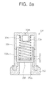
- Figs. 3A and 3B are cross section views taken along lines A-A and B-B, respectively, of Fig. 2 .
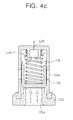
- Figs. 4A to 4C are views illustrating the operation of a spool valve included in a conventional one-way valve.
- Fig. 5 is a suction valve of a variable capacity compressor for vehicle according to an exemplary embodiment of the present invention.
- Figs. 6A and 6B are cross section views taken along lines C-C and D-D, respectively, of Fig. 5 .
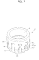
- Fig. 7 is a perspective view illustrating a spool valve included in a suction valve according to an exemplary embodiment of the present invention.
- Fig. 8 is a bottom view illustrating a spool valve included in a suction valve according to an exemplary embodiment of the present invention.
- Fig. 9 is a view illustrating that a spool valve included in a suction valve according to an exemplary embodiment of the present invention is operated to release back pressure.
- Fig. 5 is a perspective view illustrating a suction valve of a variable capacity compressor according to an exemplary embodiment of the present invention and Figs. 6A and 6B are cross section views taken along lines C-C and D-D of Fig. 5 , respectively.
- the suction valve 10 is configured so that a spool valve 40 is open by a suction force generated as a compressor (not shown) is operated to reduce the pressure in a valve case 30 and its periphery.
- the suction valve 10 requires more flow rate than an existing one-way valve, and thus, has a low spring constant (of 100gf/cm or less) so as to secure a more flow rate.
- the suction valve 10 includes a valve sheet 20 having a coolant inlet 22 formed at its center; a valve case 30 provided over the valve sheet 20 and having a plurality of coolant discharging ports 32 along the circumferential surface; a spool valve 40 selectively opening/closing the coolant inlet 22 and the coolant discharging port 32 in the valve case 30; and a resilient member 50 provided between the valve case 30 and the spool valve 40.
- the valve sheet 20 is provided at a discharging flow path 136 of the compressor 100 shown in Fig. 1 , and includes the coolant inlet 22 therein to allow for inflow of a coolant from the compressor 100.
- the valve case 30 is shaped as a cylinder whose top surface is closed, and its lower end is coupled with the upper portion of the valve sheet 20. Referring to Fig. 5 , the valve case 30 has a first coolant discharging port 32 and two second coolant discharging ports 34 with the first coolant discharging port 32 disposed therebetween.
- the first coolant discharging port 32 includes a main discharging port 32a formed as a rectangular opening on the circumferential surface of the valve case 30, and an auxiliary discharging port 32b extending from the center of the upper end of the main discharging port 32a to a portion of the top surface of the valve case 30 via the upper end of the valve case 30.
- the second coolant discharging port 34 includes a main discharging port 34a formed as a rectangular opening on the circumferential surface of the valve case 30 and located on both sides of the main discharging port 32a of the first coolant discharging port 32 with a predetermined distance, and an auxiliary discharging port 34b extending from an end portion of the upper end of the main discharging port 34a to a portion of the top surface of the valve case 30 via the upper end of the valve case 30.
- the main discharging port 34a is shown to be rectangular in Fig. 5 , the main discharging port 34 may be shaped as a triangle or a trapezoid.
- the main discharging port 32a of the first coolant discharging port 32 may be sized to be relatively greater than the main discharging port 34a of the second coolant discharging port 34.
- the main discharging port 32a of the coolant discharging port 32 may have same or slightly smaller width d as/than that D of the main discharging port 32a of the second coolant discharging port 34.
- the auxiliary discharging port 32b of the first coolant discharging port 32 may be relatively greater in size than the auxiliary discharging port 34b of the second coolant discharging port 34.
- valve case 30 does not have a separate vent hole on its top surface. Instead, the valve case 30 includes the auxiliary discharging port 32b of the first coolant discharging port 32 and the auxiliary discharging port 34b of the second coolant discharging port 34 that are extendingly formed on the top surface of the valve case 30 to replace the vent hole of the related art.
- the first coolant discharging port 32 and the two second coolant discharging ports 34 are non-uniformly arranged on the circumferential surface of the valve case 30. This is why the spool valve 40 may be brought in tight contact with the inner wall surface of the valve case 30 where the first and second coolant discharging ports 32 and 34 are formed when the pressure of the coolant is equal to the spring force of the resilient member and the spool valve 40 lifts up and down, thus preventing the spool valve 40 from being swayed left and right.
- a support 36 is extended downward from the center of the inner upper portion of the valve case 30.
- the support 36 is inserted in the resilient member 50 to support the resilient member 50 not to be swayed left and right.
- the spool valve 40 includes a receiving portion 42 in which the resilient member 50 may be inserted, a plurality of grooves 44 formed on the circumferential surface in the longitudinal direction, a strip portion 46 formed along the lower circumferential surface to have a predetermined length, and a plurality of step portions 48 formed along the inner circumferential surface.
- the plurality of grooves 44 serves to gradually open the spool valve 40 when a coolant is introduced.
- the plurality of grooves 44 may include a plurality of first grooves 44a formed in the longitudinal direction on the circumferential surface of the spool valve 40 and spaced from each other with a predetermined distance, two pairs of second grooves 44b which are formed on the first grooves 44a so that the second grooves in each pair face each other, and a plurality of third grooves 44c that are formed perpendicularly to the first or second grooves along the lower circumferential surface of the spool valve 40 and spaced from each other with a predetermined distance.
- the second grooves 44b are formed so that a coolant may be introduced from the bottom surface of the valve case 30 and the third grooves 44c are formed so that a coolant may be moved in the horizontal direction.
- the length l of the second groove 44b is formed to be shorter than the length L of the first groove 44a.
- the depth H of the second groove 44b is formed to be larger than the depth h of the first groove 44a.
- the second groove 44b starts from the bottom surface of the valve case 30 so that a coolant may be first introduced into the second groove 44b.
- the second groove 44b is formed to be spaced from the inner wall surface of the coolant inlet 22 so that a coolant may be first introduced into the second groove 44b.
- the length l of the second groove 44b may be on the order of 2/3 times the length L of the first groove 44a.
- the third groove 44c may be formed to be relatively shallow in depth compared to the first groove 44a or second groove 44b.
- the strip portion 46 is formed along the lower circumferential surface of the spool valve 40 to have a predetermined angle and a predetermined length.
- the plurality of step portions 48 includes a first step portion 48a on which an end of the resilient member 50 is seated and a second step portion 48b formed between the first step portion 48a and the inner bottom surface of the spool valve 40.
- the resilient member 50 is configured so that one end is supported by the support 36 of the valve case 30 and the other end is supported by the step portions 48 of the spool valve 40.
- the resilient member 50 returns the spool valve 40 to the original position when the pressure of coolant is released.
- a coolant is introduced from the coolant inlet 22 of the valve sheet 20 through the second groove 44b and the first groove 44a of the spool valve 40.
- the spool valve 40 is gradually opened, thus capable of reducing valve noise (low-frequency noise).
Landscapes
- Engineering & Computer Science (AREA)
- General Engineering & Computer Science (AREA)
- Mechanical Engineering (AREA)
- Compressors, Vaccum Pumps And Other Relevant Systems (AREA)
- Rotary Pumps (AREA)
- Check Valves (AREA)
- Air-Conditioning For Vehicles (AREA)
Abstract
Description
- This non-provisional application claims priority under 35 U.S.C. §119(a) on Patent Application No.
10-2009-0093279 - The present invention is directed to a valve of a variable capacity compressor for vehicle, and more particularly to a suction valve of a variable capacity compressor for vehicle that may reduce noises created between a valve case and a spool valve.
- In general, a compressor for vehicular air conditioner compresses a coolant gas supplied from an evaporator using a dynamic force and transfers the compressed coolant gas to a condenser. Among the compressors, variable capacity compressors recently gain popularity, which control the inclined angle of a swash plate to change the discharging volume.
- As shown in
Fig. 1 , a variable capacity swash plate-type compressor 100 generally includes acylinder block 110 that includes a plurality ofcylinder bores 112, asuction port 114, and asuction muffler chamber 116; afront housing 120 that is coupled with thecylinder block 110 before thecylinder block 110 to form acrank chamber 122; and arear housing 130 that is located behind thecylinder block 110 and includes asuction chamber 132, adischarging chamber 134, and adischarging path 136. - A
valve plate 140 is provided between thefront housing 120 and therear housing 130 and a coolant is introduced and discharged through thevalve plate 140. As shown inFigs. 1 and2 , thevalve plate 140 is shaped as a circular plate and includes a plurality ofcoolant suction openings 140a that are arranged along an outer circular arc and a plurality ofcoolant discharging openings 140b that are arranged along an inner circular arc. Asuction reed valve 142 is positioned in front of thevalve plate 140 and a dischargingreed valve 144 and aretainer 146 is sequentially positioned behind thevalve plate 140. A one-way valve 150 is provided to prevent a coolant from flowing back to the front of thevalve plate 140. - The variable capacity swash plate-
type compressor 100 further includes adriving shaft 160 rotatably provided at the central portion of thecylinder block 110 and thefront housing 120; aswash plate 170 connected to arotor 172 mounted at thedriving shaft 160 through ahinge portion 174 in thecrank chamber 122 so that its inclined angle varies with the pressure of thecrank chamber 122; and a plurality ofpistons 180, each interlocking with theswash plate 170 through ashoe 176 and travelling forth and back in thecylinder bore 112 according to the rotation of theswash plate 170, thus sucking and compressing the coolant. Acompression coil spring 178 is provided between theswash plate 170 and therotor 172 to return theswash plate 170 to the original position. - As the
driving shaft 160 and theswash plate 170 are rotated together, the coolant compressed in thecylinder block 110 is discharged to a condenser through thedischarging path 136 and the discharged volume of the coolant may be varied by adjusting the inclined angle of theswash plate 170. - Although the
swash plate 170 maintains the minimum inclined angle when the air conditioner of the vehicle is turned off, the angle does not become zero degree and thus the coolant is partially discharged from thevariable capacity compressor 100 to the condenser even when the air conditioner is turned off. To prevent the coolant from being discharged when the air conditioner is turned off and prevent the discharged coolant from flowing back from the condenser to thevariable capacity compressor 100, the one-way valve 150 is provided at the end of thevalve plate 140. - The conventional one-
way valve 150, as shown inFigs. 2 and3A , includes avalve sheet 152 having acoolant inlet 152a formed at the center; avalve case 154 provided over thevalve sheet 152 and having a plurality ofcoolant discharging ports 154a along the circumferential surface; aspool valve 156 selectively opening/closing thecoolant inlet 152a and thecoolant discharging port 154a in thevalve case 154; and aresilient member 158 provided between thevalve case 154 and thespool valve 156. - As shown in
Fig. 3A and3B , thevalve case 154 includes fourcoolant discharging ports 154a, one facing another with respect to the central vertical axis of thevalve case 154, and avent hole 154b at the center of the top surface of thevalve case 154 to prevent occurrence of back pressure. Thevalve case 154 further includes aguide portion 154c that extends downward from the inner surface of the top portion to guide and support theresilient member 158. - The
spool valve 156 is shaped as a cylindrical structure whose bottom surface is closed and receives theresilient member 158 therein. Thespool valve 156 is lifted up and down by pressure of the coolant in thevalve case 154 to selectively open and close thecoolant inlet 152a and thecoolant discharging port 154a. - In the conventional one-
way valve 150, however, initial opening pressure was unstable due to a delay in opening time and leakage of coolant between thevalve case 154 and thespool valve 156 when thespool valve 156 rises to initially open thecoolant discharging port 154a, thus causing noises in pipes. - In the conventional one-
way valve 150 shown inFigs. 4A and4B , immediately before thecoolant discharging port 154a is initially opened, that is, when the pressure P of the coolant is equal to the spring force F of the resilient member, thespool valve 156 was swayed left and right due to back pressure of the coolant, thus creating a valve noise (low-frequency noise). - Also, as shown in
Fig. 4C , the conventional one-way valve 150 has a structure in which back pressure exerted by thecoolant discharging port 154a right after thecoolant discharging port 154a is initially opened is difficult to release through thevent hole 154b provided at the center of the top portion. Furthermore, in the conventional one-way valve 150, a vortex flow generated while back pressure is released through thevent hole 154b caused a valve noise (high-frequency noise). - Korean Patent No.
10-0915713 - In the one-way valve disclosed in Patent Document, increase in pressure at the valve inlet by a coolant opens the spool valve to adjust the flow rate of the coolant. The one-way valve has been mainly used in a case where the resilient member has a spring constant of 100gf/cm or more. If the spring constant is set to be not more than 100gf/cm in the one-way valve, low pressure is exerted to the valve case and this incurs inflow of more coolant. Accordingly, the spool valve was easily opened even when the coolant has low pressure, and thus, a noise was created at the early stage of opening the valve. Furthermore, under the condition that the spring constant is 100gf/cm or less, back pressure was not swiftly released through the vent hole of the valve case, and this served as another source of valve noise.
- As such, the one-way valve in Patent Document could not sufficiently address the problem with the valve noise in a case where the flow rate of coolant is high or the spring constant is not more than 100gf/cm.
- Accordingly, there is a need of providing a suction valve of a variable capacity compressor for vehicle that may reduce valve noise created at the early stage of opening the spool valve even when the spring constant of the resilient member as used is 100gf/cm or less and smoothly release back pressure to decrease valve noise.
- In accordance with an exemplary embodiment of the present invention, there is provided a suction valve of a variable capacity compressor for vehicle including: a valve sheet having a coolant inlet; a valve case provided over the valve sheet and having a plurality of coolant discharging ports along the circumferential surface; a spool valve selectively opening/closing the coolant inlet and the coolant discharging port in the valve case; and a resilient member provided between the valve case and the spool valve, wherein the valve case includes a first coolant discharging port on the circumferential surface with a predetermined size and a pair of second coolant discharging ports with the first coolant discharging port disposed between the pair of second coolant discharging ports, each second coolant discharging port being smaller in size than the first coolant discharging port, and wherein the spool valve includes a plurality of first grooves formed in the longitudinal direction on the circumferential surface of the spool valve and spaced from each other with a predetermined distance, and two pairs of second grooves which are formed on the first grooves so that the second grooves in each pair face each other and a coolant may be introduced from the bottom surface of the valve case, and wherein when the spool valve is initially opened, the coolant is introduced through the first and second grooves.
- The first and second coolant discharging ports may be extended from the circumferential surface of the valve case to the top surface of the valve case.
- The spool valve further may include a plurality of third grooves that are formed perpendicularly to the first or second grooves along the lower circumferential surface of the spool valve are spaced from each other with a predetermined distance so that the coolant may be moved in the horizontal direction.
- The length of the second groove may be formed to be shorter than the length of the first groove and the third groove may be formed to be relatively shallow in depth compared to the first groove or second groove.
- In the suction valve of a variable capacity compressor for vehicle according to an exemplary embodiment of the present invention, a coolant is sequentially introduced to the first groove and the second groove when the spool valve is initially opened and this prevents pressure of the coolant from being drastically transferred. Accordingly, the spool valve may be slowly opened to reduce a valve noise (low-frequency noise). Also, since the back pressure is easily released through the first and second coolant discharging ports when the spool valve is lifted up, a vortex flow may be prevented from being generated between the valve case and the spool valve, thus decreasing the valve noise (high-frequency noise).
- In the suction valve of a variable capacity compressor for vehicle according to an exemplary embodiment of the present invention, further, the spring constant of the resilient member is adapted to be reduced and this may stably maintain the pressure in the valve when the valve is opened and closed by the resilient member. Thus, it may be possible to reduce occurrence of noise in the valve.
- The implementation of this document will be described in detail with reference to the following drawings in which like numerals refer to like elements.
-
Fig. 1 is a cross section view illustrating a general one-way valve of a variable capacity compressor for vehicle according to the related art. -
Fig. 2 is a perspective view illustrating a one-way valve of a variable capacity compressor according to the related art. -
Figs. 3A and3B are cross section views taken along lines A-A and B-B, respectively, ofFig. 2 . -
Figs. 4A to 4C are views illustrating the operation of a spool valve included in a conventional one-way valve. -
Fig. 5 is a suction valve of a variable capacity compressor for vehicle according to an exemplary embodiment of the present invention. -
Figs. 6A and6B are cross section views taken along lines C-C and D-D, respectively, ofFig. 5 . -
Fig. 7 is a perspective view illustrating a spool valve included in a suction valve according to an exemplary embodiment of the present invention. -
Fig. 8 is a bottom view illustrating a spool valve included in a suction valve according to an exemplary embodiment of the present invention. -
Fig. 9 is a view illustrating that a spool valve included in a suction valve according to an exemplary embodiment of the present invention is operated to release back pressure. - Hereinafter, exemplary embodiments of the present invention will be described in greater detail with reference to accompanying drawings.
-
Fig. 5 is a perspective view illustrating a suction valve of a variable capacity compressor according to an exemplary embodiment of the present invention andFigs. 6A and6B are cross section views taken along lines C-C and D-D ofFig. 5 , respectively. - As shown in
Figs. 5 and6A , thesuction valve 10 according to the exemplary embodiment of the present invention is configured so that aspool valve 40 is open by a suction force generated as a compressor (not shown) is operated to reduce the pressure in avalve case 30 and its periphery. Thesuction valve 10 requires more flow rate than an existing one-way valve, and thus, has a low spring constant (of 100gf/cm or less) so as to secure a more flow rate. - As shown in
Figs. 5 and6A , thesuction valve 10 includes avalve sheet 20 having acoolant inlet 22 formed at its center; avalve case 30 provided over thevalve sheet 20 and having a plurality ofcoolant discharging ports 32 along the circumferential surface; aspool valve 40 selectively opening/closing thecoolant inlet 22 and thecoolant discharging port 32 in thevalve case 30; and aresilient member 50 provided between thevalve case 30 and thespool valve 40. - The
valve sheet 20 is provided at a dischargingflow path 136 of thecompressor 100 shown inFig. 1 , and includes thecoolant inlet 22 therein to allow for inflow of a coolant from thecompressor 100. - The
valve case 30 is shaped as a cylinder whose top surface is closed, and its lower end is coupled with the upper portion of thevalve sheet 20. Referring toFig. 5 , thevalve case 30 has a firstcoolant discharging port 32 and two secondcoolant discharging ports 34 with the firstcoolant discharging port 32 disposed therebetween. - The first
coolant discharging port 32 includes a main dischargingport 32a formed as a rectangular opening on the circumferential surface of thevalve case 30, and an auxiliary dischargingport 32b extending from the center of the upper end of the main dischargingport 32a to a portion of the top surface of thevalve case 30 via the upper end of thevalve case 30. - The second
coolant discharging port 34 includes a main dischargingport 34a formed as a rectangular opening on the circumferential surface of thevalve case 30 and located on both sides of the main dischargingport 32a of the firstcoolant discharging port 32 with a predetermined distance, and an auxiliary dischargingport 34b extending from an end portion of the upper end of the main dischargingport 34a to a portion of the top surface of thevalve case 30 via the upper end of thevalve case 30. Although the main dischargingport 34a is shown to be rectangular inFig. 5 , the main dischargingport 34 may be shaped as a triangle or a trapezoid. - The main discharging
port 32a of the firstcoolant discharging port 32 may be sized to be relatively greater than the main dischargingport 34a of the secondcoolant discharging port 34. However, as shown inFig. 6B , the main dischargingport 32a of thecoolant discharging port 32 may have same or slightly smaller width d as/than that D of the main dischargingport 32a of the secondcoolant discharging port 34. The auxiliary dischargingport 32b of the firstcoolant discharging port 32 may be relatively greater in size than the auxiliary dischargingport 34b of the secondcoolant discharging port 34. - Unlike the related art, the
valve case 30 does not have a separate vent hole on its top surface. Instead, thevalve case 30 includes the auxiliary dischargingport 32b of the firstcoolant discharging port 32 and the auxiliary dischargingport 34b of the secondcoolant discharging port 34 that are extendingly formed on the top surface of thevalve case 30 to replace the vent hole of the related art. - Referring to
Fig. 5 , the firstcoolant discharging port 32 and the two secondcoolant discharging ports 34 are non-uniformly arranged on the circumferential surface of thevalve case 30. This is why thespool valve 40 may be brought in tight contact with the inner wall surface of thevalve case 30 where the first and secondcoolant discharging ports spool valve 40 lifts up and down, thus preventing thespool valve 40 from being swayed left and right. - As shown in
Fig. 6A , asupport 36 is extended downward from the center of the inner upper portion of thevalve case 30. Thesupport 36 is inserted in theresilient member 50 to support theresilient member 50 not to be swayed left and right. - Referring to
Figs. 7 and8 , thespool valve 40 includes a receivingportion 42 in which theresilient member 50 may be inserted, a plurality ofgrooves 44 formed on the circumferential surface in the longitudinal direction, astrip portion 46 formed along the lower circumferential surface to have a predetermined length, and a plurality ofstep portions 48 formed along the inner circumferential surface. The plurality ofgrooves 44 serves to gradually open thespool valve 40 when a coolant is introduced. - The plurality of
grooves 44 may include a plurality offirst grooves 44a formed in the longitudinal direction on the circumferential surface of thespool valve 40 and spaced from each other with a predetermined distance, two pairs ofsecond grooves 44b which are formed on thefirst grooves 44a so that the second grooves in each pair face each other, and a plurality ofthird grooves 44c that are formed perpendicularly to the first or second grooves along the lower circumferential surface of thespool valve 40 and spaced from each other with a predetermined distance. And, thesecond grooves 44b are formed so that a coolant may be introduced from the bottom surface of thevalve case 30 and thethird grooves 44c are formed so that a coolant may be moved in the horizontal direction. - The length l of the
second groove 44b is formed to be shorter than the length L of thefirst groove 44a. The depth H of thesecond groove 44b is formed to be larger than the depth h of thefirst groove 44a. As shown inFig. 8 , thesecond groove 44b starts from the bottom surface of thevalve case 30 so that a coolant may be first introduced into thesecond groove 44b. Referring back toFig. 6A , thesecond groove 44b is formed to be spaced from the inner wall surface of thecoolant inlet 22 so that a coolant may be first introduced into thesecond groove 44b. - Referring to
Fig. 7 , the length l of thesecond groove 44b may be on the order of 2/3 times the length L of thefirst groove 44a. - The
third groove 44c may be formed to be relatively shallow in depth compared to thefirst groove 44a orsecond groove 44b. - Accordingly, when the
spool valve 40 is open, a coolant sequentially passes through thesecond grooves 44b, thefirst grooves 44a, and thethird grooves 44c, and this may prevent pressure from being drastically transferred. - As shown in
Fig. 7 , thestrip portion 46 is formed along the lower circumferential surface of thespool valve 40 to have a predetermined angle and a predetermined length. - The plurality of
step portions 48 includes afirst step portion 48a on which an end of theresilient member 50 is seated and asecond step portion 48b formed between thefirst step portion 48a and the inner bottom surface of thespool valve 40. - The
resilient member 50 is configured so that one end is supported by thesupport 36 of thevalve case 30 and the other end is supported by thestep portions 48 of thespool valve 40. Theresilient member 50 returns thespool valve 40 to the original position when the pressure of coolant is released. - The operation of the spool valve of the suction valve according to the exemplary embodiment of the present invention will now be described with reference to
Figs. 6A to 9 . - Under the initial condition of the
spool valve 40 as shown inFig. 6A , a coolant is introduced from thecoolant inlet 22 of thevalve sheet 20 through thesecond groove 44b and thefirst groove 44a of thespool valve 40. As the coolant passes through the first andsecond grooves spool valve 40 is gradually opened, thus capable of reducing valve noise (low-frequency noise). - As shown in
Fig. 9 , when thespool valve 40 rises up, the back pressure is easily released through the firstcoolant discharging port 32 and secondcoolant discharging port 34 and this may prevent a vortex flow from occurring between thevalve case 30 and thespool valve 40, thus reducing valve noise (high-frequency noise). - The invention has been explained above with reference to exemplary embodiments. It will be evident to those skilled in the art that various modifications may be made thereto without departing from the broader spirit and scope of the invention. Further, although the invention has been described in the context its implementation in particular environments and for particular applications, those skilled in the art will recognize that the present invention's usefulness is not limited thereto and that the invention can be beneficially utilized in any number of environments and implementations. The foregoing description and drawings are, accordingly, to be regarded in an illustrative rather than a restrictive sense.
Claims (4)
- A suction valve of a variable capacity compressor for vehicle comprising: a valve sheet having a coolant inlet; a valve case provided over the valve sheet and having a plurality of coolant discharging ports along the circumferential surface; a spool valve selectively opening/closing the coolant inlet and the coolant discharging port in the valve case; and a resilient member provided between the valve case and the spool valve, wherein
the valve case includes a first coolant discharging port on the circumferential surface with a predetermined size and a pair of second coolant discharging ports with the first coolant discharging port disposed between the pair of second coolant discharging ports, each second coolant discharging port being smaller in size than the first coolant discharging port, and wherein
the spool valve includes a plurality of first grooves formed in the longitudinal direction on the circumferential surface of the spool valve and spaced from each other with a predetermined distance, and second grooves which are formed on the first grooves so that a coolant may be introduced from the bottom surface of the valve case, and wherein when the spool valve is initially opened, the coolant is introduced through the first and second grooves. - The suction valve of a variable capacity compressor for vehicle of claim 1, wherein the first and second coolant discharging ports are extended from the circumferential surface of the valve case to the top surface of the valve case.
- The suction valve of a variable capacity compressor for vehicle of claim 1, wherein the spool valve further includes a plurality of third grooves that are formed perpendicularly to the first or second grooves along the lower circumferential surface of the spool valve are spaced from each other with a predetermined distance so that the coolant may be moved in the horizontal direction.
- The suction valve of a variable capacity compressor for vehicle of claim 3, wherein the length of the second groove is formed to be shorter than the length of the first groove and the third groove is formed to be relatively shallow in depth compared to the first groove or second groove.
Applications Claiming Priority (1)
| Application Number | Priority Date | Filing Date | Title |
|---|---|---|---|
| KR20090093279A KR100940820B1 (en) | 2009-09-30 | 2009-09-30 | Suction valve of variable capacity compressor for vehicle |
Publications (3)
| Publication Number | Publication Date |
|---|---|
| EP2362097A2 true EP2362097A2 (en) | 2011-08-31 |
| EP2362097A3 EP2362097A3 (en) | 2012-06-27 |
| EP2362097B1 EP2362097B1 (en) | 2013-07-31 |
Family
ID=42083093
Family Applications (1)
| Application Number | Title | Priority Date | Filing Date |
|---|---|---|---|
| EP20100172391 Not-in-force EP2362097B1 (en) | 2009-09-30 | 2010-08-10 | Suction Valve of Variable Capacity Compressor for Vehicle |
Country Status (4)
| Country | Link |
|---|---|
| US (1) | US8276614B2 (en) |
| EP (1) | EP2362097B1 (en) |
| KR (1) | KR100940820B1 (en) |
| PT (1) | PT2362097E (en) |
Cited By (1)
| Publication number | Priority date | Publication date | Assignee | Title |
|---|---|---|---|---|
| EP3061969A1 (en) | 2015-02-26 | 2016-08-31 | Comet S.p.A. | A check valve |
Families Citing this family (30)
| Publication number | Priority date | Publication date | Assignee | Title |
|---|---|---|---|---|
| KR20110062109A (en) * | 2009-12-02 | 2011-06-10 | 현대자동차주식회사 | Intake check valve of vehicle air conditioner compressor |
| KR101693042B1 (en) * | 2010-06-08 | 2017-01-04 | 한온시스템 주식회사 | Variable displacement swash plate type compressor |
| KR20130033864A (en) * | 2011-09-27 | 2013-04-04 | 삼성전기주식회사 | An pressure valve for energy storage device and energy storage device including the same |
| KR101120841B1 (en) * | 2012-01-05 | 2012-03-16 | 김기연 | Check valve of variable capacity compressor vehicle |
| KR101258795B1 (en) | 2012-02-02 | 2013-04-26 | 김기연 | Structure for removal dust of check valve of variable capacity compressor vehicle |
| KR200470033Y1 (en) * | 2012-05-10 | 2013-11-25 | (주)신한전기 | Check valve of variable capacity compressor vehicle |
| DE102012222823A1 (en) | 2012-06-28 | 2014-01-02 | Robert Bosch Gmbh | Piston fuel pump |
| KR101935805B1 (en) * | 2013-02-20 | 2019-01-08 | 한온시스템 주식회사 | Intake checking valve |
| US9309978B2 (en) * | 2013-03-14 | 2016-04-12 | Dresser-Rand Company | Low head to stem ratio poppet valve |
| KR101467972B1 (en) * | 2013-09-17 | 2014-12-02 | 동일기계공업 주식회사 | Check Valve Usable as a Suction or Discharge Valve |
| CN103775689A (en) * | 2014-02-20 | 2014-05-07 | 沈阳航天新光集团有限公司 | Low flow resistance air channel one-way valve |
| US9360126B2 (en) * | 2014-04-29 | 2016-06-07 | National Synchrotron Radiation Research Center | Relief valve assembly with anti-frozen shielding hat |
| US20170356412A1 (en) * | 2015-01-26 | 2017-12-14 | Hitachi Automotive Systems, Ltd. | Valve mechanism and high-pressure fuel supply pump including valve mechanism |
| EP3104054A1 (en) * | 2015-06-09 | 2016-12-14 | Siemens Aktiengesellschaft | Non-return valve |
| JP2017115684A (en) * | 2015-12-24 | 2017-06-29 | 株式会社豊田自動織機 | Compressor check valve |
| JP6424813B2 (en) * | 2015-12-24 | 2018-11-21 | 株式会社豊田自動織機 | Compressor check valve |
| JP6380367B2 (en) * | 2015-12-24 | 2018-08-29 | 株式会社豊田自動織機 | Compressor check valve |
| US10591074B2 (en) | 2016-07-21 | 2020-03-17 | Hanon Systems | Suction dampening device with internal dampening for vehicle air conditioning compressor |
| KR102671320B1 (en) | 2016-08-24 | 2024-06-03 | 한온시스템 주식회사 | Suction pulsation reduction device of swash plate type compressor |
| KR102076967B1 (en) * | 2017-04-11 | 2020-02-13 | 한온시스템 주식회사 | Suction pulsation reduction device and swash plate type compressor having the same |
| CN109720327B (en) * | 2017-10-20 | 2022-08-02 | 株式会社万都 | Check valve |
| US11280332B2 (en) * | 2018-05-03 | 2022-03-22 | Daniel K. Zitting | Valve and seat with seal |
| KR102602359B1 (en) * | 2018-11-22 | 2023-11-16 | 에이치엘만도 주식회사 | Check valve and moudulator block including it |
| US20220260164A1 (en) * | 2019-05-21 | 2022-08-18 | Swagelok Company | Check valve |
| DE102019133665A1 (en) * | 2019-12-10 | 2021-06-10 | Schaeffler Technologies AG & Co. KG | Valve and device for regulating pressures of a fluid |
| DE102019133667B4 (en) * | 2019-12-10 | 2025-08-28 | Schaeffler Technologies AG & Co. KG | Device for regulating pressures of a fluid with a valve |
| DE102020110181A1 (en) * | 2020-04-14 | 2021-10-14 | Hanon Systems | Device for damping pressure pulsations for a compressor of a gaseous fluid |
| DE102020116993A1 (en) * | 2020-06-29 | 2021-12-30 | Schaeffler Technologies AG & Co. KG | Valve and method of controlling a fluid with the valve |
| DE102020116992A1 (en) * | 2020-06-29 | 2021-12-30 | Schaeffler Technologies AG & Co. KG | Valve device with a valve seated in a valve seat |
| CN118251562A (en) | 2021-11-17 | 2024-06-25 | 斯瓦戈洛克公司 | Check valve |
Citations (1)
| Publication number | Priority date | Publication date | Assignee | Title |
|---|---|---|---|---|
| KR100915713B1 (en) | 2009-05-21 | 2009-09-04 | 동일기계공업 주식회사 | One way valve of variable capacity compressor for vehicle |
Family Cites Families (8)
| Publication number | Priority date | Publication date | Assignee | Title |
|---|---|---|---|---|
| US4874066A (en) * | 1987-12-04 | 1989-10-17 | S.U.I. Corporation | Variable flow shock absorber and method |
| DE4320826C2 (en) * | 1993-06-23 | 1997-07-10 | Uraca Pumpen | Automatic valve |
| JP2000346241A (en) * | 1999-06-07 | 2000-12-15 | Toyota Autom Loom Works Ltd | Check valve |
| DE102004033022A1 (en) * | 2004-07-08 | 2006-02-02 | Ina-Schaeffler Kg | check valve |
| JP2006200552A (en) * | 2005-01-18 | 2006-08-03 | Fuji Koki Corp | Check valve |
| JP4656044B2 (en) * | 2006-11-10 | 2011-03-23 | 株式会社豊田自動織機 | Compressor suction throttle valve |
| JP2009103336A (en) * | 2007-10-22 | 2009-05-14 | Tgk Co Ltd | Refrigerating cycle, variable capacity compressor and discharge valve |
| KR100909910B1 (en) | 2008-04-11 | 2009-07-29 | 동일기계공업 주식회사 | One-way valve of variable capacity compressor for automotive air conditioner |
-
2009
- 2009-09-30 KR KR20090093279A patent/KR100940820B1/en active Active
-
2010
- 2010-06-30 US US12/827,367 patent/US8276614B2/en not_active Expired - Fee Related
- 2010-08-10 EP EP20100172391 patent/EP2362097B1/en not_active Not-in-force
- 2010-08-10 PT PT101723914T patent/PT2362097E/en unknown
Patent Citations (1)
| Publication number | Priority date | Publication date | Assignee | Title |
|---|---|---|---|---|
| KR100915713B1 (en) | 2009-05-21 | 2009-09-04 | 동일기계공업 주식회사 | One way valve of variable capacity compressor for vehicle |
Cited By (1)
| Publication number | Priority date | Publication date | Assignee | Title |
|---|---|---|---|---|
| EP3061969A1 (en) | 2015-02-26 | 2016-08-31 | Comet S.p.A. | A check valve |
Also Published As
| Publication number | Publication date |
|---|---|
| PT2362097E (en) | 2013-09-11 |
| US8276614B2 (en) | 2012-10-02 |
| EP2362097A3 (en) | 2012-06-27 |
| KR100940820B1 (en) | 2010-02-04 |
| US20110076171A1 (en) | 2011-03-31 |
| EP2362097B1 (en) | 2013-07-31 |
Similar Documents
| Publication | Publication Date | Title |
|---|---|---|
| US8276614B2 (en) | Suction valve of variable capacity compressor for vehicle | |
| US8276613B2 (en) | One-way valve of variable capacity compressor for vehicle | |
| US7918656B2 (en) | Suction throttle valve of a compressor | |
| JP4656044B2 (en) | Compressor suction throttle valve | |
| US8439652B2 (en) | Suction throttle valve for variable displacement type compressor | |
| EP2096308B1 (en) | Swash plate type variable displacement compressor | |
| EP1394418A2 (en) | Vane compressor | |
| US20070253837A1 (en) | Variable capacity swash plate type compressor | |
| JP2005337232A (en) | Variable capacity compressor | |
| US6837695B2 (en) | Inlet port for a reciprocating compressor | |
| JP5123715B2 (en) | Swash plate compressor | |
| JP2005315176A (en) | Piston variable displacement compressor | |
| US20080120991A1 (en) | Compressor having a mechanism for separating and recovering lubrication oil | |
| US20040109778A1 (en) | Compressor having a discharge valve mechanism including a valve retainer having a specially-designed curved surface | |
| US6748971B2 (en) | Discharge valve assembly of fluid machinery | |
| US20050196291A1 (en) | Piston compressor | |
| JP6881375B2 (en) | Piston compressor | |
| JP7511702B2 (en) | Swash plate compressor | |
| JP2004239096A (en) | Variable displacement compressor | |
| JP4642505B2 (en) | Capacity control valve for variable capacity swash plate compressor | |
| JP4195812B2 (en) | Gas compressor | |
| WO2021039847A1 (en) | Piston-type compressor | |
| JP2008106715A (en) | Compression machine | |
| JP2021032237A (en) | Piston type compressor | |
| EP1041284A2 (en) | Suction valve for compressor |
Legal Events
| Date | Code | Title | Description |
|---|---|---|---|
| PUAI | Public reference made under article 153(3) epc to a published international application that has entered the european phase |
Free format text: ORIGINAL CODE: 0009012 |
|
| 17P | Request for examination filed |
Effective date: 20100810 |
|
| AK | Designated contracting states |
Kind code of ref document: A2 Designated state(s): AL AT BE BG CH CY CZ DE DK EE ES FI FR GB GR HR HU IE IS IT LI LT LU LV MC MK MT NL NO PL PT RO SE SI SK SM TR |
|
| AX | Request for extension of the european patent |
Extension state: BA ME RS |
|
| PUAL | Search report despatched |
Free format text: ORIGINAL CODE: 0009013 |
|
| AK | Designated contracting states |
Kind code of ref document: A3 Designated state(s): AL AT BE BG CH CY CZ DE DK EE ES FI FR GB GR HR HU IE IS IT LI LT LU LV MC MK MT NL NO PL PT RO SE SI SK SM TR |
|
| AX | Request for extension of the european patent |
Extension state: BA ME RS |
|
| RIC1 | Information provided on ipc code assigned before grant |
Ipc: F04B 53/10 20060101ALI20120523BHEP Ipc: F04B 27/10 20060101AFI20120523BHEP Ipc: F04B 53/00 20060101ALI20120523BHEP Ipc: F04B 39/10 20060101ALI20120523BHEP Ipc: F04B 39/00 20060101ALI20120523BHEP Ipc: F16K 15/02 20060101ALI20120523BHEP |
|
| GRAP | Despatch of communication of intention to grant a patent |
Free format text: ORIGINAL CODE: EPIDOSNIGR1 |
|
| RIC1 | Information provided on ipc code assigned before grant |
Ipc: F04B 39/00 20060101ALI20130122BHEP Ipc: F16K 15/02 20060101ALI20130122BHEP Ipc: F04B 27/10 20060101AFI20130122BHEP Ipc: F04B 53/00 20060101ALI20130122BHEP Ipc: F04B 53/10 20060101ALI20130122BHEP Ipc: F04B 39/10 20060101ALI20130122BHEP |
|
| GRAS | Grant fee paid |
Free format text: ORIGINAL CODE: EPIDOSNIGR3 |
|
| GRAA | (expected) grant |
Free format text: ORIGINAL CODE: 0009210 |
|
| AK | Designated contracting states |
Kind code of ref document: B1 Designated state(s): AL AT BE BG CH CY CZ DE DK EE ES FI FR GB GR HR HU IE IS IT LI LT LU LV MC MK MT NL NO PL PT RO SE SI SK SM TR |
|
| REG | Reference to a national code |
Ref country code: GB Ref legal event code: FG4D Ref country code: CH Ref legal event code: EP |
|
| REG | Reference to a national code |
Ref country code: AT Ref legal event code: REF Ref document number: 624815 Country of ref document: AT Kind code of ref document: T Effective date: 20130815 |
|
| REG | Reference to a national code |
Ref country code: IE Ref legal event code: FG4D |
|
| REG | Reference to a national code |
Ref country code: PT Ref legal event code: SC4A Free format text: AVAILABILITY OF NATIONAL TRANSLATION Effective date: 20130904 |
|
| REG | Reference to a national code |
Ref country code: DE Ref legal event code: R096 Ref document number: 602010008982 Country of ref document: DE Effective date: 20130926 |
|
| REG | Reference to a national code |
Ref country code: AT Ref legal event code: MK05 Ref document number: 624815 Country of ref document: AT Kind code of ref document: T Effective date: 20130731 |
|
| REG | Reference to a national code |
Ref country code: NL Ref legal event code: VDEP Effective date: 20130731 |
|
| REG | Reference to a national code |
Ref country code: LT Ref legal event code: MG4D |
|
| PG25 | Lapsed in a contracting state [announced via postgrant information from national office to epo] |
Ref country code: IS Free format text: LAPSE BECAUSE OF FAILURE TO SUBMIT A TRANSLATION OF THE DESCRIPTION OR TO PAY THE FEE WITHIN THE PRESCRIBED TIME-LIMIT Effective date: 20131130 Ref country code: CY Free format text: LAPSE BECAUSE OF FAILURE TO SUBMIT A TRANSLATION OF THE DESCRIPTION OR TO PAY THE FEE WITHIN THE PRESCRIBED TIME-LIMIT Effective date: 20130619 Ref country code: SE Free format text: LAPSE BECAUSE OF FAILURE TO SUBMIT A TRANSLATION OF THE DESCRIPTION OR TO PAY THE FEE WITHIN THE PRESCRIBED TIME-LIMIT Effective date: 20130731 Ref country code: BE Free format text: LAPSE BECAUSE OF FAILURE TO SUBMIT A TRANSLATION OF THE DESCRIPTION OR TO PAY THE FEE WITHIN THE PRESCRIBED TIME-LIMIT Effective date: 20130731 Ref country code: LT Free format text: LAPSE BECAUSE OF FAILURE TO SUBMIT A TRANSLATION OF THE DESCRIPTION OR TO PAY THE FEE WITHIN THE PRESCRIBED TIME-LIMIT Effective date: 20130731 Ref country code: NO Free format text: LAPSE BECAUSE OF FAILURE TO SUBMIT A TRANSLATION OF THE DESCRIPTION OR TO PAY THE FEE WITHIN THE PRESCRIBED TIME-LIMIT Effective date: 20131031 Ref country code: HR Free format text: LAPSE BECAUSE OF FAILURE TO SUBMIT A TRANSLATION OF THE DESCRIPTION OR TO PAY THE FEE WITHIN THE PRESCRIBED TIME-LIMIT Effective date: 20130731 Ref country code: AT Free format text: LAPSE BECAUSE OF FAILURE TO SUBMIT A TRANSLATION OF THE DESCRIPTION OR TO PAY THE FEE WITHIN THE PRESCRIBED TIME-LIMIT Effective date: 20130731 |
|
| PG25 | Lapsed in a contracting state [announced via postgrant information from national office to epo] |
Ref country code: GR Free format text: LAPSE BECAUSE OF FAILURE TO SUBMIT A TRANSLATION OF THE DESCRIPTION OR TO PAY THE FEE WITHIN THE PRESCRIBED TIME-LIMIT Effective date: 20131101 Ref country code: SI Free format text: LAPSE BECAUSE OF FAILURE TO SUBMIT A TRANSLATION OF THE DESCRIPTION OR TO PAY THE FEE WITHIN THE PRESCRIBED TIME-LIMIT Effective date: 20130731 Ref country code: NL Free format text: LAPSE BECAUSE OF FAILURE TO SUBMIT A TRANSLATION OF THE DESCRIPTION OR TO PAY THE FEE WITHIN THE PRESCRIBED TIME-LIMIT Effective date: 20130731 Ref country code: LV Free format text: LAPSE BECAUSE OF FAILURE TO SUBMIT A TRANSLATION OF THE DESCRIPTION OR TO PAY THE FEE WITHIN THE PRESCRIBED TIME-LIMIT Effective date: 20130731 Ref country code: PL Free format text: LAPSE BECAUSE OF FAILURE TO SUBMIT A TRANSLATION OF THE DESCRIPTION OR TO PAY THE FEE WITHIN THE PRESCRIBED TIME-LIMIT Effective date: 20130731 Ref country code: FI Free format text: LAPSE BECAUSE OF FAILURE TO SUBMIT A TRANSLATION OF THE DESCRIPTION OR TO PAY THE FEE WITHIN THE PRESCRIBED TIME-LIMIT Effective date: 20130731 |
|
| PG25 | Lapsed in a contracting state [announced via postgrant information from national office to epo] |
Ref country code: CY Free format text: LAPSE BECAUSE OF FAILURE TO SUBMIT A TRANSLATION OF THE DESCRIPTION OR TO PAY THE FEE WITHIN THE PRESCRIBED TIME-LIMIT Effective date: 20130731 |
|
| PG25 | Lapsed in a contracting state [announced via postgrant information from national office to epo] |
Ref country code: MC Free format text: LAPSE BECAUSE OF FAILURE TO SUBMIT A TRANSLATION OF THE DESCRIPTION OR TO PAY THE FEE WITHIN THE PRESCRIBED TIME-LIMIT Effective date: 20130731 Ref country code: DK Free format text: LAPSE BECAUSE OF FAILURE TO SUBMIT A TRANSLATION OF THE DESCRIPTION OR TO PAY THE FEE WITHIN THE PRESCRIBED TIME-LIMIT Effective date: 20130731 Ref country code: SK Free format text: LAPSE BECAUSE OF FAILURE TO SUBMIT A TRANSLATION OF THE DESCRIPTION OR TO PAY THE FEE WITHIN THE PRESCRIBED TIME-LIMIT Effective date: 20130731 Ref country code: DE Free format text: LAPSE BECAUSE OF NON-PAYMENT OF DUE FEES Effective date: 20140301 Ref country code: EE Free format text: LAPSE BECAUSE OF FAILURE TO SUBMIT A TRANSLATION OF THE DESCRIPTION OR TO PAY THE FEE WITHIN THE PRESCRIBED TIME-LIMIT Effective date: 20130731 Ref country code: CZ Free format text: LAPSE BECAUSE OF FAILURE TO SUBMIT A TRANSLATION OF THE DESCRIPTION OR TO PAY THE FEE WITHIN THE PRESCRIBED TIME-LIMIT Effective date: 20130731 Ref country code: RO Free format text: LAPSE BECAUSE OF FAILURE TO SUBMIT A TRANSLATION OF THE DESCRIPTION OR TO PAY THE FEE WITHIN THE PRESCRIBED TIME-LIMIT Effective date: 20130731 |
|
| REG | Reference to a national code |
Ref country code: IE Ref legal event code: MM4A |
|
| REG | Reference to a national code |
Ref country code: DE Ref legal event code: R119 Ref document number: 602010008982 Country of ref document: DE Effective date: 20140301 |
|
| REG | Reference to a national code |
Ref country code: HU Ref legal event code: AG4A Ref document number: E019026 Country of ref document: HU |
|
| PG25 | Lapsed in a contracting state [announced via postgrant information from national office to epo] |
Ref country code: ES Free format text: LAPSE BECAUSE OF FAILURE TO SUBMIT A TRANSLATION OF THE DESCRIPTION OR TO PAY THE FEE WITHIN THE PRESCRIBED TIME-LIMIT Effective date: 20130731 Ref country code: IT Free format text: LAPSE BECAUSE OF FAILURE TO SUBMIT A TRANSLATION OF THE DESCRIPTION OR TO PAY THE FEE WITHIN THE PRESCRIBED TIME-LIMIT Effective date: 20130731 |
|
| PLBE | No opposition filed within time limit |
Free format text: ORIGINAL CODE: 0009261 |
|
| STAA | Information on the status of an ep patent application or granted ep patent |
Free format text: STATUS: NO OPPOSITION FILED WITHIN TIME LIMIT |
|
| 26N | No opposition filed |
Effective date: 20140502 |
|
| REG | Reference to a national code |
Ref country code: FR Ref legal event code: ST Effective date: 20140618 |
|
| PG25 | Lapsed in a contracting state [announced via postgrant information from national office to epo] |
Ref country code: IE Free format text: LAPSE BECAUSE OF NON-PAYMENT OF DUE FEES Effective date: 20130810 |
|
| PG25 | Lapsed in a contracting state [announced via postgrant information from national office to epo] |
Ref country code: FR Free format text: LAPSE BECAUSE OF NON-PAYMENT OF DUE FEES Effective date: 20130930 |
|
| REG | Reference to a national code |
Ref country code: CH Ref legal event code: PL |
|
| GBPC | Gb: european patent ceased through non-payment of renewal fee |
Effective date: 20140810 |
|
| PG25 | Lapsed in a contracting state [announced via postgrant information from national office to epo] |
Ref country code: CH Free format text: LAPSE BECAUSE OF NON-PAYMENT OF DUE FEES Effective date: 20140831 Ref country code: LI Free format text: LAPSE BECAUSE OF NON-PAYMENT OF DUE FEES Effective date: 20140831 |
|
| PG25 | Lapsed in a contracting state [announced via postgrant information from national office to epo] |
Ref country code: SM Free format text: LAPSE BECAUSE OF FAILURE TO SUBMIT A TRANSLATION OF THE DESCRIPTION OR TO PAY THE FEE WITHIN THE PRESCRIBED TIME-LIMIT Effective date: 20130731 |
|
| PG25 | Lapsed in a contracting state [announced via postgrant information from national office to epo] |
Ref country code: MT Free format text: LAPSE BECAUSE OF FAILURE TO SUBMIT A TRANSLATION OF THE DESCRIPTION OR TO PAY THE FEE WITHIN THE PRESCRIBED TIME-LIMIT Effective date: 20130731 Ref country code: TR Free format text: LAPSE BECAUSE OF FAILURE TO SUBMIT A TRANSLATION OF THE DESCRIPTION OR TO PAY THE FEE WITHIN THE PRESCRIBED TIME-LIMIT Effective date: 20130731 |
|
| PG25 | Lapsed in a contracting state [announced via postgrant information from national office to epo] |
Ref country code: GB Free format text: LAPSE BECAUSE OF NON-PAYMENT OF DUE FEES Effective date: 20140810 Ref country code: BG Free format text: LAPSE BECAUSE OF FAILURE TO SUBMIT A TRANSLATION OF THE DESCRIPTION OR TO PAY THE FEE WITHIN THE PRESCRIBED TIME-LIMIT Effective date: 20130731 Ref country code: MK Free format text: LAPSE BECAUSE OF FAILURE TO SUBMIT A TRANSLATION OF THE DESCRIPTION OR TO PAY THE FEE WITHIN THE PRESCRIBED TIME-LIMIT Effective date: 20130731 Ref country code: LU Free format text: LAPSE BECAUSE OF NON-PAYMENT OF DUE FEES Effective date: 20130810 |
|
| PG25 | Lapsed in a contracting state [announced via postgrant information from national office to epo] |
Ref country code: AL Free format text: LAPSE BECAUSE OF FAILURE TO SUBMIT A TRANSLATION OF THE DESCRIPTION OR TO PAY THE FEE WITHIN THE PRESCRIBED TIME-LIMIT Effective date: 20130731 |
|
| PGFP | Annual fee paid to national office [announced via postgrant information from national office to epo] |
Ref country code: HU Payment date: 20210717 Year of fee payment: 12 |
|
| PG25 | Lapsed in a contracting state [announced via postgrant information from national office to epo] |
Ref country code: PT Free format text: LAPSE BECAUSE OF NON-PAYMENT OF DUE FEES Effective date: 20220210 |
|
| PG25 | Lapsed in a contracting state [announced via postgrant information from national office to epo] |
Ref country code: PT Free format text: LAPSE BECAUSE OF NON-PAYMENT OF DUE FEES Effective date: 20220210 |
|
| PGFP | Annual fee paid to national office [announced via postgrant information from national office to epo] |
Ref country code: PT Payment date: 20220708 Year of fee payment: 12 |
|
| PGRI | Patent reinstated in contracting state [announced from national office to epo] |
Ref country code: PT Effective date: 20220715 |
|
| PG25 | Lapsed in a contracting state [announced via postgrant information from national office to epo] |
Ref country code: PT Free format text: LAPSE BECAUSE OF NON-PAYMENT OF DUE FEES Effective date: 20230210 |
|
| PG25 | Lapsed in a contracting state [announced via postgrant information from national office to epo] |
Ref country code: HU Free format text: LAPSE BECAUSE OF NON-PAYMENT OF DUE FEES Effective date: 20220811 |