EP2361797A1 - Gas tank - Google Patents
Gas tank Download PDFInfo
- Publication number
- EP2361797A1 EP2361797A1 EP20110152083 EP11152083A EP2361797A1 EP 2361797 A1 EP2361797 A1 EP 2361797A1 EP 20110152083 EP20110152083 EP 20110152083 EP 11152083 A EP11152083 A EP 11152083A EP 2361797 A1 EP2361797 A1 EP 2361797A1
- Authority
- EP
- European Patent Office
- Prior art keywords
- pressure
- main body
- heat
- tank main
- gas
- Prior art date
- Legal status (The legal status is an assumption and is not a legal conclusion. Google has not performed a legal analysis and makes no representation as to the accuracy of the status listed.)
- Granted
Links
Images


Classifications
-
- B—PERFORMING OPERATIONS; TRANSPORTING
- B60—VEHICLES IN GENERAL
- B60K—ARRANGEMENT OR MOUNTING OF PROPULSION UNITS OR OF TRANSMISSIONS IN VEHICLES; ARRANGEMENT OR MOUNTING OF PLURAL DIVERSE PRIME-MOVERS IN VEHICLES; AUXILIARY DRIVES FOR VEHICLES; INSTRUMENTATION OR DASHBOARDS FOR VEHICLES; ARRANGEMENTS IN CONNECTION WITH COOLING, AIR INTAKE, GAS EXHAUST OR FUEL SUPPLY OF PROPULSION UNITS IN VEHICLES
- B60K15/00—Arrangement in connection with fuel supply of combustion engines or other fuel consuming energy converters, e.g. fuel cells; Mounting or construction of fuel tanks
- B60K15/03—Fuel tanks
- B60K15/03006—Gas tanks
-
- Y—GENERAL TAGGING OF NEW TECHNOLOGICAL DEVELOPMENTS; GENERAL TAGGING OF CROSS-SECTIONAL TECHNOLOGIES SPANNING OVER SEVERAL SECTIONS OF THE IPC; TECHNICAL SUBJECTS COVERED BY FORMER USPC CROSS-REFERENCE ART COLLECTIONS [XRACs] AND DIGESTS
- Y10—TECHNICAL SUBJECTS COVERED BY FORMER USPC
- Y10T—TECHNICAL SUBJECTS COVERED BY FORMER US CLASSIFICATION
- Y10T137/00—Fluid handling
- Y10T137/1842—Ambient condition change responsive
- Y10T137/1939—Atmospheric
- Y10T137/1963—Temperature
Definitions
- the present invention relates to a gas tank.
- Such a fuel cell vehicle is also equipped with, in addition to the fuel cell, a hydrogen tank (gas tank) that supplies hydrogen (a fuel gas) to the fuel cell, a compressor that supplies air, a coolant pump that circulates a coolant so as to flow through the fuel cell, a PDU (Power Drive Unit) that converts DC power to AC power, a motor for travelling, and a drive train that transmits the driving force generated by the motor to driving wheels.
- a hydrogen tank gas tank
- a compressor that supplies air
- a coolant pump that circulates a coolant so as to flow through the fuel cell
- PDU Power Drive Unit
- a drive train that transmits the driving force generated by the motor to driving wheels.
- External devices including the compressor, the coolant pump, the PDU, and the drive train generate heat when being actuated.
- the hydrogen tank is filled with hydrogen at a high pressure, and a hydrogen supply path through which hydrogen supplied from the hydrogen tank to the fuel cell flows is provided with a plurality of pressure-reduction valves (regulators).
- a target pressure of hydrogen is set in accordance with electricity-generation requisite level calculated based on the open level of an accelerator or the like, and the pressure-reduction valves are controlled so that the secondary-side pressure of the pressure-reduction valves becomes the calculated target pressure.
- JP2001-130271A discloses a structure of a fuel tank which suppresses generation of a fuel vapor due to heat input into the fuel tank in which a liquid fuel (gasoline) is stored, thereby suppressing a negative effect to a fuel consumption or the like.
- a first aspect of the present invention provides a gas tank comprising: a tank main body filled with a gas; a heat-insulating layer provided on an external surface of the tank main body; a pressure-reduction device which is provided at one end of the tank main body, and which reduces a pressure in the tank main body by releasing the gas from the tank main body; and a transferring component which extends from the pressure-reduction device toward the other end of the tank main body, and which transfers heat and pressure, in which the pressure-reduction device is actuated based on a detection operation by the transferring component, and releases the gas from the tank main body, thereby reducing the pressure in the tank main body.
- the heat-insulating layer is provided on the external surface of the tank main body, heat from the external device (e.g., a compressor) arranged around the gas tank is blocked by the heat-insulating layer. Hence, the temperature of gas filled in the tank main body is unlikely to increase, and thus pressure thereof is unlikely to increase.
- the external device e.g., a compressor
- the transferring component extending from one end of the tank main body to the other end thereof, and the transferring component outputs detection of heat, i.e., an increase in temperature, to the pressure-reduction device which is thermally connected to the transferring component.
- the pressure-reduction device is actuated based on the detection operation by the transferring component, and releases the gas from the tank main body, thereby decreasing the pressure in the tank main body. Accordingly, the pressure of gas filled in the tank main body is unlikely to increase.
- the transferring component detects the heat, and the pressure-reduction device is actuated, so that the pressure in the tank main body is unlikely to increase.
- the regulator for controlling the pressure of gas supplied from the gas tank is a wide range type, and a system (including the regulator) for receiving gas supply (i.e., a fuel cell system in the following embodiment) can be simplified and inexpensive. Also, because the primary-side pressure of the regulator, etc., is unlikely to increase, gas can be supplied to an apparatus which needs the gas (i.e., a fuel cell in the following embodiment) after the pressure of gas is controlled appropriately by using the regulator.
- a second aspect of the present invention provides the gas tank of the first aspect of the present invention, in which the heat-insulating layer is formed by applying a thermofoamable heat-insulating paint on the external surface of the tank main body, starts foaming when a temperature increases, and becomes the heat-insulating layer.
- the heat-insulating layer can be easily formed by applying the thermofoamable heat-insulating paint.
- a third aspect of the present invention provides the gas tank of the first aspect of the present invention, in which the heat-insulating layer includes a heat-insulating member fixed on the external surface of the tank main body.
- the heat-insulating layer can be easily formed by fixing the heat-insulating member on the external surface of the tank main body.
- a fourth aspect of the present invention provides the gas tank of any one of the first to third aspects of the present invention, in which the transferring component includes a part which constitutes the tank main body and which has a thermal conductivity, the pressure-reduction device is thermally connected to the transferring component, and heat is transferred from the transferring component to the pressure-reduction device.
- the part e.g., a liner in the following embodiment
- the part configuring the tank main body has a thermal conductivity
- heat input can be detected by the part itself That is, the gas tank has no individual part as the transferring component, so that the number of parts of the gas tank can be reduced, and the structure of the gas tank can be simplified.
- a fifth aspect of the present invention provides the gas tank of any one of the first to third aspects of the present invention, in which the transferring component includes a thermally expandable substance filled in the transferring component, and a pressure increasing together with a thermal expansion of the substance is transferred to the pressure-reduction device.
- the increase in temperature of the substance and the increase in pressure are transmitted as a pressure and output from the transferring component to the pressure-reduction device.
- the pressure-reduction device is actuated upon detection of pressure (a pressure increased together with the increase in pressure inside the transferring component) input from the transferring component in order to release gas from the tank main body, thereby decreasing the pressure in the tank main body
- the transferring component even if the transferring component is locally heated, when the temperature of the substance thereinside increases, the substance thermally expands, and the pressure inside the transferring component also increases. Because a pressure is propagated more rapidly than a temperature, the pressure inside the transferring component encapsulating the substance uniformly and rapidly increases. This causes the pressure transmission input into the pressure-reduction device from the transferring component to rapidly increase, and the pressure-reduction device releases gas from the tank main body by utilizing the increased pressure transmission, thereby decreasing the pressure in the tank main body.
- a sixth aspect of the present invention provides the gas tank of the fifth aspect of the present invention, in which the substance thermally expands together with a phase-change when heated, and the pressure-reduction device obtains a thrust force for releasing the gas from the tank main body based on an increased pressure in the transferring component.
- the encapsulated substance thermally expands together with a phase-change when heated, and the pressure inside the transferring component 5 increases.
- pressure input into the pressure-reduction device from the transferring component also increases.
- the pressure-reduction device obtains a thrust force from the increasing pressure, and quickly releases the gas from the tank main body.
- a seventh aspect of the present invention provides the gas tank of the fifth or sixth aspect of the present invention, in which the substance thermally expands when being boiled.
- An eighth aspect of the present invention provides the gas tank of any one of the fifth to seventh aspects of the present invention, in which the substance is a liquid at a normal temperature (25 °C). According to such a gas tank, the transferring component can be easily constituted.
- a ninth aspect of the present invention provides the gas tank of any one of the fifth to seventh aspects of the present invention, in which the substance is a solid at a normal temperature (25 °C). Such a gas tank will hardly be affected by the posture of the transferring component.
- a tenth aspect of the present invention provides the gas tank of any one of the fifth to ninth aspects of the present invention, in which the transferring component is formed in a tubular shape, and has one end connected to the pressure-reduction device, and the one end has an opening portion which is opened when an internal pressure of the transferring component becomes equal to or greater than a predetermined pressure, and which transfers a pressure by the substance to the pressure-reduction device.
- the opening portion is opened. Also, the pressure by the substance (the pressure inside the transferring component) is transmitted (input) from the one end of the transferring component to the pressure-reduction device.
- An eleventh aspect of the present invention provides the gas tank of any one of the first to tenth aspects of the present invention, further comprising a meltable member which is provided in the pressure-reduction device, and which melts down when its temperature becomes equal to or greater than a predetermined temperature in order to cause the pressure-reduction device to release the gas from the tank main body, in which a low-sensitive treatment for lowering a sensitivity to heat is performed on a portion of the transferring component near the pressure-reduction device, and a high-sensitive treatment for improving the sensitivity to heat is performed on another portion of the transferring component apart from the pressure-reduction device.
- a twelfth aspect of the present invention provides the gas tank of any one of the first to eleventh aspects of the present invention, in which the tank main body is installed in a vehicle, and the pressure-reduction device is arranged at a right or a left of the tank main body in a vehicle-width direction.
- the pressure-reduction device is arranged at the right or left of the tank main body in the vehicle-width direction, so that when a vehicle is compressed in the vehicle-length direction by a collision, etc., the pressure-reduction device can be protected and the gas tank which suppresses increasing of a gas pressure can be maintained.
- FIGS. 1 to 6 A first embodiment of the present invention will be explained with reference to FIGS. 1 to 6 .
- a fuel cell vehicle 100 (hereinafter, referred to as a travelling object) of this embodiment includes a fuel cell stack 110 (a fuel cell), a hydrogen tank 1 (a gas tank), a pressure-reduction valve 121, a compressor 131, and a dilution unit 132. More specifically, the fuel cell vehicle 100 may be, for example, a four-wheel vehicle, a three-wheel cycle, a two-wheel vehicle, a unicycle, or a train.
- the fuel cell stack 110 is a solid-polymer type fuel cell (Polymer Electrolyte Fuel Cell: PEFC), and has a plurality of stacked cells each including an MEA (Membrane Electrode Assembly) sandwiched between separators (not shown).
- the MEA has an electrolyte membrane (solid-polymer membrane), and a cathode and an anode sandwiching the MEA.
- Each separator is provided with an anode path 111 (a fuel gas path) and a cathode path 112 (an oxidant gas path) which are grooves or through-holes.
- the hydrogen tank 1 is filled with hydrogen (a fuel gas) supplied to the anode path 111.
- the hydrogen tank 1 is connected to an inlet of the anode path 111 through a piping 121 a, the pressure-reduction valve 121 (a regulator), and a piping 121b, so that hydrogen in the hydrogen tank 1 is supplied to the anode path 111 through the piping 121a, etc..
- the piping 121a and the piping 121b constitute a hydrogen supply path (a fuel gas supply path) which is provided with the pressure-reduction valve 121.
- the hydrogen supply path is provided with a normally closed shutoff valve that is controlled and opened/closed by an ECU (Electronic Control Unit, not shown).
- a plurality of pressure-reduction valves and shutoff valves are provided in the following order toward the downstream, i.e., a primary shutoff valve, a primary pressure-reduction valve, a secondary shutoff valve, and a secondary pressure-reduction valve.
- the pressure-reduction valve 121 is a primary pressure-reduction valve to reduce the pressure of hydrogen based on a pilot pressure input from a piping 121c so that the pressure of hydrogen in the anode path 111 and the pressure of air in the cathode path 112 are balanced as disclosed in ,T,P2004-185831 A of this applicant.
- the upstream side of the piping 121 is connected to a piping 13Ia where air flows toward the cathode path 112.
- An outlet of the anode path 111 is connected to the dilution unit 132 through a piping 121d.
- An anode-off gas exhausted from the anode path 111 is ejected to the dilution unit 132 through the piping 121d.
- the compressor 131 is connected to an inlet of the cathode path 112 through a piping 131a, is actuated in accordance with an instruction given by the ECU, takes in air including oxygen, compresses the taken air, and pumps the compressed air to the cathode path 112.
- the compressor 131 is energized by the fuel cell stack 110, or a high-voltage battery (not shown), etc..
- the compressor 131 is a heat source that generates actuation heat when being actuated.
- the compressor 131 is an external device generating heat from the standpoint of the hydrogen tank 1.
- the external device generating heat in this fashion includes various devices, such as the ECU, a coolant pump, the high-voltage battery, a PDU, and a drive train, and the compressor 131.
- An outlet of the cathode path 112 is connected to the dilution unit 132 through a piping 132a.
- a cathode-off gas exhausted from the cathode path 112 is ejected to the dilution unit 132 through the piping 132a.
- the piping 132a is provided with a normally opened back pressure valve (not shown) that has an open level controlled by the ECU. That is, the ECU calculates a required amount of power generation, a target air pressure, and a target hydrogen pressure based on the open level of an accelerator, and controls the open level of the back pressure valve and the revolution speed of the compressor 131 so as to obtain the target air pressure.
- the dilution unit 132 dilutes hydrogen included in the anode-off gas from the piping 121d with the cathode-off gas from the piping 132a, thereby decreasing a hydrogen concentration, and has a dilution space in the dilution unit 132.
- the diluted gas is exhausted to the exterior of the vehicle through a piping 132b.
- the hydrogen tank 1 has a substantially cylindrical external shape, and is laterally provided relative to the fuel cell vehicle 100, and has the axial direction consistent with the vehicle width direction (right-and-left direction).
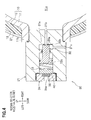
- the hydrogen tank 1 includes a tank main body 10, a thermofoamable heat-insulating layer 21 formed around the external surface 13 of the tank main body 10 entirely, a relief valve 30 (pressure-reduction device) provided at the left-end side (the one end side) of the tank main body 10, and a metal body 40 (a meltable member) built in the relief valve 30.
- the hydrogen tank 1 is fixed to the frame (the vehicle body) of the fuel cell vehicle 100 by means of, for example, a metal belt (not shown).
- the tank main body 10 has a substantially cylindrical external shape, and as shown in FIGS. 2 and 3 , is made of a liner 11 and a CFRP (Carbon Fiber Reinforced Plastic), etc., and also has a reinforcement layer 12 covering the outer circumference surface of the liner 11, so that the tank main body 10 has a double-layer structure.
- CFRP Carbon Fiber Reinforced Plastic
- the liner 11 extends from the relief valve 30 provided at the left-end side (the one end side) of the tank main body 10 to the right-end side (the other-end side) of the tank main body 10.
- the liner 11 is formed of an aluminum alloy, etc., and has a thermal conductivity. Accordingly, the liner 11 functions as transferring component for detecting the increase in temperature of the hydrogen tank 1, and detection of such increase in temperature is made through transmission of heat across the liner 11. That is, since the hydrogen tank 1 detects heat input through the liner 11 itself that is the framework of the hydrogen tank 1, and since the hydrogen tank 1 has no additional part as the transferring component, the number of parts can be reduced, thereby accomplishing a simple and lightweight structure.
- the material of the liner 11 is not limited to an aluminum alloy, and may be, for example, a copper alloy, or a resin (a resin containing dispersed metal chips) having an enhanced thermal conductivity.
- the interior of the liner 11 serves as a tank room 11 a where hydrogen is filled and stored.
- the liner 11 has a neck part 11b to which a valve body 31 of the relief valve 30 is screwed to the left portion of the liner 11.
- the reinforcing layer 12 is obtained by, for example, winding up a long carbon fiber impregnated with a thermosetting resin in a predetermined manner, and by causing the thermosetting resin to be cured.
- the specific structure of the tank main body 10 is not limited to such a double-layer structure of those liner 11 and reinforcing layer 12.
- the specific structure of the tank main body 10 may be a monolayer structure of only a liner formed of a synthetic resin or a metal.
- thermofoamable heat-insulating layer 21 is a layer containing a constituent that is a foaming agent like poly-ammonium-phosphate, and when heated from the exterior, the temperature of such a layer increases, and when reaching a foaming temperature, such a layer generates a gas and foams, thereby forming a heat-insulating layer 21A (a foam layer) having a large number of foams formed in the interior thereof (see FIG. 5 ).
- thermofoamable heat-insulating layer 21 can be easily formed by, for example, applying a conventionally well-known thermofoamable heat-insulating paint containing a constituent that is a foaming agent like poly-ammonium-phosphate on the whole external surface 13 of the tank main body 10 (the reinforcing layer 12).
- thermofoamable heat-insulating layer 21 foams can be set and changed appropriately by changing the foaming agent that generates a gas when its temperature increases. That is, the foaming temperature of the thermofoamable heat-insulating layer 21 is set, and its design is changed appropriately in accordance with the temperature of the external device such as the compressor 131 that generates heat.
- thermofoamable heat-insulating layer 21 is not limited to a monolayer structure, and may employ a multilayer structure having layers each of which has different foaming temperature. Furthermore, an undercoat may be formed between the thermofoamable heat-insulating layer 21 and the tank main body 10, and a topcoat may be formed on the thermofoamable heat-insulating layer 21.
- the relief valve 30 is a normally closed valve provided at the left of the tank main body 10, and when it opens, hydrogen in the tank main body 10 is released to the exterior, thereby reducing the pressure in the interior of the tank main body 10. Accordingly, when the fuel cell vehicle 100 is compressed in the vehicle-length direction by collision, the relief valve 30 is not compressed and can be protected from such collision.
- the relief valve 30 includes the valve body 31 screwed to the neck 11b, a valve element 32 (a piston) that moves back and forth in the valve body 31, a compression coil spring 33 that urges the valve element 32 toward the closed direction (the right), and a cap 34 that maintains the compression coil spring 33 to be loaded in the valve body 31.
- the valve body 31 and the neck 11 b (the liner 11) are thermally coupled together.
- the valve body 31 is provided with a normally closed shutoff valve (an in-tank solenoid valve) (not shown) which is controlled to open/close by the ECU, and which is controlled to open when hydrogen is supplied to the fuel cell stack 110.
- the valve body 31 has a valve seat 31a which the valve element 32 touches when the valve is closed, and has a first port 31b and a second port 31c which are formed in the interior of the valve body 31 and which serve as a path of releasing hydrogen when the valve is opened.
- the valve seat 31 a is provided with an O-ring 36a for improving the sealing capability when the valve is closed.
- the valve element 32 has a large-diameter part 32a integrally formed at the left (one end side) thereof, and a small-diameter part 32b extending from the large-diameter part 32a to the right (the other-end side).
- the small-diameter part 32b touches the valve seat 31a (the O-ring 3 6a) of the valve body 31 in a normal condition (when the valve is closed) in order to plug off the first port 31b and the second port 31c, thereby closing the relief valve 30.
- a normal condition means a condition in which the interior of the tank main body 10 is at a pressure equal to or less than a rated pressure, and the above-explained metal body 40 is not melted yet.
- the above-explained metal body 40 is provided between the compression coil spring 33 and the cap 34, and is formed of a low-melting-point metal (e.g., a tin or indium alloy), that melts down, when the temperature thereof increases equal to or greater than a predetermined temperature.
- a low-melting-point metal e.g., a tin or indium alloy
- valve element 32 slides to the left by means of high-pressure hydrogen in the tank main body 10, i.e., the valve element 32 is moved apart from the valve seat 31a, and at the same time, the first port 31b and the second port 31 c are communicated with each other, so that hydrogen in the tank main body 10 is released to the exterior through the first and second ports 31b, 31c, thereby reducing the pressure in the tank main body 10.
- the heat propagating path 34a of the cap 34 is provided with a filter 35, and external heat can be propagated to the metal body 40 through the filter 35, and the melted piece of the metal body 40 can flow out to the exterior through the filter 35,
- a filter 35 can be formed of a foam metal or a porous metal obtained by sintering.
- thermofoamable heat-insulating layer 21 When the temperature of the thermofoamable heat-insulating layer 21 increases and reaches a predetermined foaming temperature due to heat transferred from the compressor 131, the thermofoamable heat-insulating layer 21 starts foaming, and becomes the heat-insulating layer 21A (see FIG 5 ). Accordingly, heat transferred from the compressor 131 is blocked by the heat-insulating layer 21 A. Therefore, the temperature of hydrogen filled in the tank main body 10 hardly increases, and the pressure of hydrogen hardly increases.
- the pressure-reduction valve 121 can adjust and reduce the pressure of hydrogen. appropriately, and the hydrogen is supplied to the anode path 111 at an appropriate pressure, thereby preventing the fuel cell stack 110 from being deteriorated by hydrogen supplied at an unexpected high pressure. It is possible to reduce the opportunity that hydrogen directly goes through the fuel cell stack 110, and the fuel consumption of the fuel cell stack 110, i.e., the consumption efficiency of hydrogen improves.
- the hydrogen tank 1 may be a stationary hydrogen tank 1.
- the gas tank may be a natural gas tank which supplies a natural gas to a CNG (Compressed Natural Gas) engine.
- CNG Compressed Natural Gas
- the present invention is not limited to combustible gas, and the tank main body 10 may be filled with, for example, oxygen, nitrogen, argon, etc..
- a hydrogen tank 2 of the second embodiment has, instead of the thermofoamable heat-insulating layer 21, a heat-insulating member 22 (a cover) which is fixed on the external surface 13 of the tank main body 10, and which initially has heat-insulating properties so as to serve a heat-insulating layer as it is. That is, it is unnecessary to apply a thermofoamable heat-insulating paint in order to form the thermofoamable heat-insulating layer 21, thus the hydrogen tank 2 can be simplified. Also, because the heat-insulating member 22 has a predetermined thickness, the hydrogen tank 2 hardly be deformed.
- the heat-insulating member 22 comprises two vertically separated pieces, i.e., an upper half and a lower half, and is bonded, and fixed by using a bond or fastened and fixed by using a bolt, etc.. Also, the heat-insulating member 22 may be provided with a hook, and may be attached to the tank main body 10 by snap fitting through such a hook.
- a hydrogen tank 3 of the third embodiment has, in addition to the configuration of the hydrogen tank 1 of the first embodiment, a bar-shaped heat pipe 51 (transferring component) arranged in the tank room 11 a.
- the left end of the heat pipe 51 is screwed to and fixed to the valve body 31 (see FIG 9 ). That is, the heat pipe 51 is thermally coupled to the relief valve 30.
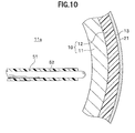
- the heat pipe 51 extends from the relief valve 30 provided at the left end of the tank main body 10 toward the right end of the tank main body 10 in the tank room 11a (see FIG. 10 ).
- a heat-insulating member 52 is provided on the surface of the heat pipe 5 other than the left end and the right end.
- the heat-insulating member 52 is provided on the surface of the heat pipe 51, heat transferred by the heat pipe 51 is unlikely to be dissipated to hydrogen filled in the tank room 11 a through the halfway of the heat pipe 51, but is rapidly transferred to the relief valve 30. Accordingly, the relief valve 30 can be actuated without a delay.
- a hydrogen tank 4 of the fourth embodiment has, in addition to the configuration of the hydrogen tank 1 of the first embodiment, a tubular thermosensitive tube 60 (transferring component) having water W (material) filled in the interior thereof.
- a vapor room 31d where the water W (vapor and liquid, hereinafter referred to as vapor, etc.,) flows from the thermosensitive tube 60 is formed in the interior of the valve body 31.
- the vapor, etc. pushes the large-diameter part 32a of the valve element 32 to the left, so that the valve element 32 slides to the left and is moved apart from the valve seat 31a.
- the first and second ports 31b, 31 are communicated with each other, the relief valve 30 is opened, and hydrogen in the tank main body 10 is released to the exterior through the first and second ports 31b, 31c, thereby reducing the pressure in the tank main body 10.
- the relief valve 30 obtains pressing force (thrust force) that pushes the valve element 32 to the left (the direction in which the relief valve 30 opens) in order to release hydrogen based on the pressure by vapor, etc., entering into the vapor room 31d.
- pressing force thrust force
- an O-ring 36b, an O-ring 36c are attached between the large-diameter part 32a, the small-diameter part 32b, and the valve body 31.
- the thermosensitive tube 60 detects a temperature of the tank main body 10 and that in the vicinity of the tank main body 10, converts the detected temperature to a transmission of pressure, and outputs such a transmission to the relief valve 30.
- the thermosensitive tube 60 is wound up around the tank main body 10 approximately one round and a half in the vehicle width direction (see FIG 11 ). That is, the thermosensitive tube 60 is provided around the tank main body 10 so as to run along the outer circumference surface of the tank main body 10, and detects heat at (any one of) the non-wound portions of the tank main body 10 and those in the vicinity thereof.
- thermosensitive tube 60 is made of a tubular metal having anticorrosion properties like a stainless steel alloy, and has a simple structure in which the water W (the material) is enclosed therein and which is easily produced. That is, the interior of the thermosensitive tube 60 is filled with the water W
- the water W is a liquid at a normal temperature (25 °C) and at a normal pressure (1 atm).
- a normal temperature 25 °C
- a normal pressure 1 atm
- thermosensitive tube 60 and the tank main body 1 0 are partially heated by heat transferred from the compressor 131, the filled water W (the liquid) is subjected to increase in temperature, is boiled, and is subjected to phase-change to vapor (a gas), thereby increasing its volume (thermal expansion). Accordingly, the pressure in the thermosensitive tube 60 uniformly increases, and is rapidly propagated to a portion where a notch 62 to be discussed later is formed. In contrast, since the temperature is less easily propagated than the pressure, a temperature difference is likely to occur
- thermosensitive tube 60 One end 61 of the thermosensitive tube 60 is connected to the vapor room 31d formed in the valve body 31 of the relief valve 30. That is, the thermosensitive tube 60 is thermally connected to the relief valve 30. Note that an O-ring 36d is provided between the one end 6l. of the thermosensitive tube 60 and the valve body 31 in order to prevent leakage of vapor, etc..
- the notch 62 (a notched portion to be an opening portion) which breaks off when the thermosensitive tube 60 is heated, the water W is boiled, and the pressure in the thermosensitive tube 60 becomes equal to or greater than a predetermined pressure is formed as the one end 61 of the thermosensitive tube 60.
- the thickness of the thermosensitive tube 60 becomes thin at the notch 62. That is, the notch 62 is an example of the releasing portion which performs an open operation when the pressure in the thermosensitive tube 60 becomes equal to or greater than the predetermined pressure, and which transmits the pressure of the water W(the material) to the relief valve 30 (pressure-reduction device).
- the opening portion is not limited to the a notch 62.
- the opening portion may employ a structure that an opening formed in the thermosensitive tube 60 is plugged off by a small plug, and when the pressure in the thermosensitive tube 60 becomes equal to or greater than the predetermined pressure, the plug is removed from the opening and the opening portion is opened.
- the thermosensitive tube 60 may employ a structure that the opening portion itself is a small relief valve.
- the notch 62 breaks off, i.e., performs an open operation, vapor and the water W (the liquid) in the thermosensitive tube 60 flow in the vapor room 31 d, and the pressure in the thermosensitive tube 60 is input into the relief valve 30.
- the vapor, etc., flowed in the vapor room 31d with equal to or greater than a predetermined pressure pushes the large-diameter part 32a of the valve element 32 against the compression coil spring 33, thereby opening the relief valve 30.
- a force fl (see FTG 13) by the vapor, etc., flowed in the vapor room 31d and pushing the valve element 32 in the valve opening direction (the left) is given by calculating a product of the pressure by the vapor, etc., at the time of flow-in and an operation area S 1 of the large-diameter part 32a that is pushed by the vapor, etc., in the valve opening direction. That is, for example, if the large-diameter part 32a is enlarged in the radial direction with the small-diameter part 32b remaining same, the operation area S1 becomes large, so that it is easy to change the setting that the relief valve 30 is opened even if the pressure by the vapor, etc., is low.
- thermosensitive tube 60 extends to the right end (the other-end side) along the rear side portion of the external surface 13 (see FIG 12 ) of the tank main body 10, continuously extends to the left end along the front side portion of the external surface 13, and continuously extends to the right end along the rear side portion of the external surface 13. Accordingly, even if heat is input from the right of the hydrogen tank 4, such heat can be rapidly detected by the thermosensitive tube 60.
- fins 64, 64 for improving the sensitivity to heat are provided at respective right side portions 63, 63 of the thermosensitive tube 60 apart from the relief valve 30, and thus a high-sensitive treatment to heat is performed on the thermosensitive tube 60. Accordingly, when heat is input to the right part of the fuel cell vehicle 100 apart from the relief valve 30, such heat is rapidly transferred to the thermo sensitive tube 60 through the finns 64, and the thermosensitive tube 60 can rapidly detect heat from the above-explained high heat source.
- thermosensitive tube 60 in the vehicle-width direction, a foam heat-insulating body 66 (a sponge) which lowers the sensitivity to heat and which has a heat-insulating property is provided at the left portion 65 of the thermosensitive tube 60 near the relief valve 30, and thus a low-sensitive treatment to heat is performed on the thermosensitive tube 60. Accordingly, when heat is input from the left portion near the relief valve 30, the thermosensitive tube 60 is unlikely to detect such heat, so that the internal pressure thereof is unlikely to increase.
- a foam heat-insulating body 66 a sponge
- thermosensitive tube 60 the specific examples of the high and low-sensitive treatments to the thermosensitive tube 60 are not limited to the fins 64 and the foam heat-insulating body 66.
- a high-sensitive treatment may be applied by painting the thermosensitive tube 60 with a black paint in order to form a black coating layer 67.
- thermosensitive tube 60 when heat is input from the right of the hydrogen tank 4, such heat is transferred to the thermo sensitive tube 60 and the water W (the liquid) filled therein through the fins 64.
- the temperature of the water W increases, and the water W boils at 100 °C. That is, the water W is subjected to thermal expansion, and the pressure in the thermosensitive tube 60 increases.
- the pressure in the thermosensitive tube 60 becomes equal to or greater than a predetermined pressure, the notch 62 breaks off, vapor (the gas) and the water W (the liquid) flow into the vapor room 31d, and a pressure is input into the relief valve 3 0 from the thermosensitive tube 60.
- the vapor, etc., flowing in the vapor room 31 d pushes the valve element 32 in the valve opening direction, and the relief valve 30 is opened. This causes hydrogen in the tank main body 10 to be released to the exterior, and thus the pressure in the tank main body 10 decreases.
- thermosensitive tube 60 employs a structure that the water W that is a liquid at a normal temperature and a normal pressure (a standard condition, 25 °C, 1 atm) is filled in the thermosensitive tube 60
- the present invention is not limited to this structure.
- the substance filled in the thermosensitive tube 60 may be any material which is boiled or sublimed near a target valve opening temperature, at which the relief valve 30 must be opened, in order to increase the pressure in the thermosensitive tube 60 to a predetermined pressure and which is not resolved at the target valve opening temperature. That is, the phase-change of a substance near the target valve opening temperature is not limited to from a liquid to a gas, but may be from a solid to a gas.
- such a substance may be hydrocarbon, alcohol, ether, chlorofluorocarbon, an oil, ammonium, or a mixture thereof.
- a wax or the like which is solid at a normal temperature and a normal pressure may be filled in the thermosensitive tube 60. According to a structure in which the solid substance is filled, an effect by a posture of the thermosensitive tube 60 (the fuel cell vehicle 100) can be further eliminated. Also, as long as the operation for opening the valve is limited to once, a substance which is resolved at the target valve opening temperature but can increase the pressure in the thermosensitive tube 60 can be used.
- thermosensitive tube 60 pushes the valve element 32 in the valve opening direction to open the relief valve 30 in the foregoing fourth embodiment
- a structure in which the flowing vapor, etc., breaks a thin part of the relief valve in order to form a releasing hole communicated with the exterior, and hydrogen is released to the exterior through such a releasing opening may be employed.
- thermosensitive tube 60 is connected to the vapor room 31 d of the relief valve 30
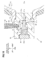
- two thermosensitive tubes 60, 60 may be connected as shown in FIG 15 .
- thermosensitive tube 60 is connected to the relief valve 30 attached to the tank main body 10 filled with hydrogen
- a configuration in which the thermosensitive tube 60 is connected to a relief valve attached to a high pressure gas tube where a high pressure gas flows may be employed.
- a gas tank that suppresses an increase in pressure of a gas filled therein.
- a hydrogen tank comprises a tank main body filled with hydrogen, a thermofoamable heat-insulating layer provided on the external surface of the tank main body, a relief valve which is provided at the left end of the tank main body and which reduces the pressure in the tank main body by releasing the hydrogen in the tank main body, and a liner which extends from the relief valve toward the right end and which detects an increase in temperature.
- the relief valve is thermally connected to the liner, and is actuated based on heat transferred from the liner in order to release the hydrogen in the tank main body, thereby reducing the pressure in the tank main body.
Landscapes
- Engineering & Computer Science (AREA)
- Life Sciences & Earth Sciences (AREA)
- Sustainable Development (AREA)
- Sustainable Energy (AREA)
- Chemical & Material Sciences (AREA)
- Combustion & Propulsion (AREA)
- Transportation (AREA)
- Mechanical Engineering (AREA)
- Filling Or Discharging Of Gas Storage Vessels (AREA)
- Fuel Cell (AREA)
Abstract
Description
- The present invention relates to a gas tank.
- Recently, development of a fuel cell vehicle which is equipped with a fuel cell and which runs by its electrical power is progressed. Such a fuel cell vehicle is also equipped with, in addition to the fuel cell, a hydrogen tank (gas tank) that supplies hydrogen (a fuel gas) to the fuel cell, a compressor that supplies air, a coolant pump that circulates a coolant so as to flow through the fuel cell, a PDU (Power Drive Unit) that converts DC power to AC power, a motor for travelling, and a drive train that transmits the driving force generated by the motor to driving wheels.
External devices including the compressor, the coolant pump, the PDU, and the drive train generate heat when being actuated. - The hydrogen tank is filled with hydrogen at a high pressure, and a hydrogen supply path through which hydrogen supplied from the hydrogen tank to the fuel cell flows is provided with a plurality of pressure-reduction valves (regulators). A target pressure of hydrogen is set in accordance with electricity-generation requisite level calculated based on the open level of an accelerator or the like, and the pressure-reduction valves are controlled so that the secondary-side pressure of the pressure-reduction valves becomes the calculated target pressure.
- It is a different case from hydrogen (a gas) filled in the hydrogen tank, but
JP2001-130271A - Meanwhile, in the case of fuel cell vehicle, when the vehicle travels under a high temperature condition like midsummer or when the external devices, a compressor, etc., generate heat as explained above so that heat is input into the hydrogen tank, hydrogen expands and the pressure in the hydrogen tank increases.
When the pressure of hydrogen in the hydrogen tank increases, the primary-side pressure of the above-explained pressure-reduction valves also increases, so that hydrogen is likely to be supplied to the fuel cell at a higher pressure than the target pressure. Such hydrogen supply at a high pressure often causes the fuel cell to poorly consume hydrogen and results in deterioration of the fuel cell. - Installation of a wide-range pressure-reduction valve with a wide control range can be considered in this case, but such a wide-range pressure-reduction valve is remarkably expensive, and thus becomes costly.
- It is an object of the present invention to provide a gas tank that suppresses increase of a gas pressure filled in the interior thereof.
- In order to achieve the above object, a first aspect of the present invention provides a gas tank comprising: a tank main body filled with a gas; a heat-insulating layer provided on an external surface of the tank main body; a pressure-reduction device which is provided at one end of the tank main body, and which reduces a pressure in the tank main body by releasing the gas from the tank main body; and a transferring component which extends from the pressure-reduction device toward the other end of the tank main body, and which transfers heat and pressure, in which the pressure-reduction device is actuated based on a detection operation by the transferring component, and releases the gas from the tank main body, thereby reducing the pressure in the tank main body.
- According to such a gas tank, because the heat-insulating layer is provided on the external surface of the tank main body, heat from the external device (e.g., a compressor) arranged around the gas tank is blocked by the heat-insulating layer. Hence, the temperature of gas filled in the tank main body is unlikely to increase, and thus pressure thereof is unlikely to increase.
- Also, even if heat from the external device is not completely blocked and some of such heat is transferred to the gas filled in the tank main body and the interior thereof, this heat is detected by the transferring component extending from one end of the tank main body to the other end thereof, and the transferring component outputs detection of heat, i.e., an increase in temperature, to the pressure-reduction device which is thermally connected to the transferring component.
The pressure-reduction device is actuated based on the detection operation by the transferring component, and releases the gas from the tank main body, thereby decreasing the pressure in the tank main body. Accordingly, the pressure of gas filled in the tank main body is unlikely to increase. - If heat transferred from the external device is blocked by the heat-insulating layer thus way, and if some of such heat is not blocked, i.e., some of such heat is transferred, the transferring component detects the heat, and the pressure-reduction device is actuated, so that the pressure in the tank main body is unlikely to increase.
- Therefore, it is not necessary that the regulator for controlling the pressure of gas supplied from the gas tank is a wide range type, and a system (including the regulator) for receiving gas supply (i.e., a fuel cell system in the following embodiment) can be simplified and inexpensive.
Also, because the primary-side pressure of the regulator, etc., is unlikely to increase, gas can be supplied to an apparatus which needs the gas (i.e., a fuel cell in the following embodiment) after the pressure of gas is controlled appropriately by using the regulator. - A second aspect of the present invention provides the gas tank of the first aspect of the present invention, in which the heat-insulating layer is formed by applying a thermofoamable heat-insulating paint on the external surface of the tank main body, starts foaming when a temperature increases, and becomes the heat-insulating layer.
- According to such a gas tank, the heat-insulating layer can be easily formed by applying the thermofoamable heat-insulating paint.
- A third aspect of the present invention provides the gas tank of the first aspect of the present invention, in which the heat-insulating layer includes a heat-insulating member fixed on the external surface of the tank main body.
- According to such a gas tank, the heat-insulating layer can be easily formed by fixing the heat-insulating member on the external surface of the tank main body.
- A fourth aspect of the present invention provides the gas tank of any one of the first to third aspects of the present invention, in which the transferring component includes a part which constitutes the tank main body and which has a thermal conductivity, the pressure-reduction device is thermally connected to the transferring component, and heat is transferred from the transferring component to the pressure-reduction device.
- According to such a gas tank, because the part (e.g., a liner in the following embodiment) configuring the tank main body has a thermal conductivity, heat input can be detected by the part itself That is, the gas tank has no individual part as the transferring component, so that the number of parts of the gas tank can be reduced, and the structure of the gas tank can be simplified.
- A fifth aspect of the present invention provides the gas tank of any one of the first to third aspects of the present invention, in which the transferring component includes a thermally expandable substance filled in the transferring component, and a pressure increasing together with a thermal expansion of the substance is transferred to the pressure-reduction device.
- According to such a gas tank, when heat is transferred to the gas tank from the external device and the temperature of the tank main body increases, the temperature of the transferring component and that of the substance therein increase. This causes the substance filled in the transferring component to thermally expand, and the pressure inside the transferring component increases, thereby detecting the increase in temperature. That is, it is detected that any part of the tank main body is heated by heat from the external device.
- The increase in temperature of the substance and the increase in pressure are transmitted as a pressure and output from the transferring component to the pressure-reduction device.
The pressure-reduction device is actuated upon detection of pressure (a pressure increased together with the increase in pressure inside the transferring component) input from the transferring component in order to release gas from the tank main body, thereby decreasing the pressure in the tank main body - That is, even if the transferring component is locally heated, when the temperature of the substance thereinside increases, the substance thermally expands, and the pressure inside the transferring component also increases. Because a pressure is propagated more rapidly than a temperature, the pressure inside the transferring component encapsulating the substance uniformly and rapidly increases.
This causes the pressure transmission input into the pressure-reduction device from the transferring component to rapidly increase, and the pressure-reduction device releases gas from the tank main body by utilizing the increased pressure transmission, thereby decreasing the pressure in the tank main body. - A sixth aspect of the present invention provides the gas tank of the fifth aspect of the present invention, in which the substance thermally expands together with a phase-change when heated, and the pressure-reduction device obtains a thrust force for releasing the gas from the tank main body based on an increased pressure in the transferring component.
- According to such a gas tank, the encapsulated substance thermally expands together with a phase-change when heated, and the pressure inside the transferring component 5 increases. Correspondingly to this operation, pressure input into the pressure-reduction device from the transferring component also increases. The pressure-reduction device obtains a thrust force from the increasing pressure, and quickly releases the gas from the tank main body.
- A seventh aspect of the present invention provides the gas tank of the fifth or sixth aspect of the present invention, in which the substance thermally expands when being boiled.
- According to such a gas tank, when the encapsulated substance is boiled, the substance thermally expands, and the pressure inside the transferring component can rapidly increase.
- An eighth aspect of the present invention provides the gas tank of any one of the fifth to seventh aspects of the present invention, in which the substance is a liquid at a normal temperature (25 °C).
According to such a gas tank, the transferring component can be easily constituted. - A ninth aspect of the present invention provides the gas tank of any one of the fifth to seventh aspects of the present invention, in which the substance is a solid at a normal temperature (25 °C).
Such a gas tank will hardly be affected by the posture of the transferring component. - A tenth aspect of the present invention provides the gas tank of any one of the fifth to ninth aspects of the present invention, in which the transferring component is formed in a tubular shape, and has one end connected to the pressure-reduction device, and the one end has an opening portion which is opened when an internal pressure of the transferring component becomes equal to or greater than a predetermined pressure, and which transfers a pressure by the substance to the pressure-reduction device.
- According to such a gas tank, when the pressure inside the transferring component formed in a tubular shape becomes equal to or greater than a predetermined pressure, the opening portion is opened. Also, the pressure by the substance (the pressure inside the transferring component) is transmitted (input) from the one end of the transferring component to the pressure-reduction device.
- An eleventh aspect of the present invention provides the gas tank of any one of the first to tenth aspects of the present invention, further comprising a meltable member which is provided in the pressure-reduction device, and which melts down when its temperature becomes equal to or greater than a predetermined temperature in order to cause the pressure-reduction device to release the gas from the tank main body, in which a low-sensitive treatment for lowering a sensitivity to heat is performed on a portion of the transferring component near the pressure-reduction device, and a high-sensitive treatment for improving the sensitivity to heat is performed on another portion of the transferring component apart from the pressure-reduction device.
- According to such a gas tank, when the heat from the external device is transferred to a part apart from the pressure-reduction device, since a high-sensitive treatment for improving the sensitivity to heat is applied to the portion of the transferring component apart from the pressure-reduction device, the transferring component can rapidly detect heat generated at a distant location and transferred from the external device.
- On the other hand, when the heat from the external device is input to a part near the pressure-reduction device, such heat is transferred to the meltable member provided in the pressure-reduction device, and such a meltable member melts down when its temperature becomes equal to or greater than a predetermined temperature, which causes the pressure-reduction device to release gas from the tank main body. That is, since a low-sensitivity treatment for lowering a sensitivity to heat is applied to the portion of the transferring component near the pressure-reduction device, a gas release based on whether or not the meltable member provided in the pressure-reduction device melts down takes precedence over the detection of heat by the transferring component.
- A twelfth aspect of the present invention provides the gas tank of any one of the first to eleventh aspects of the present invention, in which the tank main body is installed in a vehicle, and the pressure-reduction device is arranged at a right or a left of the tank main body in a vehicle-width direction.
- According to such a gas tank, because the pressure-reduction device is arranged at the right or left of the tank main body in the vehicle-width direction, so that when a vehicle is compressed in the vehicle-length direction by a collision, etc., the pressure-reduction device can be protected and the gas tank which suppresses increasing of a gas pressure can be maintained.
-
-
FIG 1 is a side view showing a fuel cell vehicle according to a first embodiment of the present invention; -
FIG 2 is a side cross-sectional view of a hydrogen tank according to the first embodiment, and shows a normal condition; -
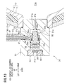
FIG. 3 is a side cross-sectional view of the hydrogen tank according to the fuss embodiment, and shows a high temperature condition (a condition in which heat is input); -
FIG 4 is a side cross-sectional view of the major part of the hydrogen tank according to the first embodiment, and shows a condition (a normal condition) in which a relief valve is closed; -
FIG 5 is a side cross-sectional view of the major part of the hydrogen tank according to the first embodiment, and shows a condition (a high temperature condition) in which the relief valve is opened; -
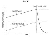
FIG. 6 is a graph showing an effect of the hydrogen tank according to the first embodiment; -
FIG 7 is a side cross-sectional view of a hydrogen tank according to a second embodiment; -
FIG. 8 is a side cross-sectional view of a hydrogen tank according to a third embodiment; -
FIG. 9 is a side cross-sectional view of the hydrogen tank according to the third embodiment, and is an enlarged view of the left portion (the one end side) of the hydrogen tank; -
FIG. 10 is a side cross-sectional view of the hydrogen tank according to the third embodiment, and is an enlarged view of the right portion (the other-end side) of the hydrogen tank; -
FIG. 11 is a side view of a hydrogen tank according to a fourth embodiment; -
FIG 12 is a side cross-sectional view of the left portion of the hydrogen tank according to the fourth embodiment, and shows a condition (a normal condition) in which a relief valve is closed; -
FIG 13 is a side cross-sectional view of the left portion of the hydrogen tank according to the fourth embodiment, and shows a condition (a high temperature condition) in which the relief value is opened; -
FIG. 14 is a diagram showing examples of low-sensitive treatment and high-sensitive treatment performed on a thermosensitive tube according to the fourth embodiment; -
FIG. 15 is a side view of a hydrogen tank according to a modified example; and -
FIG. 16 is a side cross-sectional view of the hydrogen tank according to the modified example, and shows a condition in which a relief valve is closed (a normal condition). - A first embodiment of the present invention will be explained with reference to
FIGS. 1 to 6 . - A fuel cell vehicle 100 (hereinafter, referred to as a travelling object) of this embodiment includes a fuel cell stack 110 (a fuel cell), a hydrogen tank 1 (a gas tank), a pressure-
reduction valve 121, acompressor 131, and adilution unit 132.
More specifically, thefuel cell vehicle 100 may be, for example, a four-wheel vehicle, a three-wheel cycle, a two-wheel vehicle, a unicycle, or a train. - The
fuel cell stack 110 is a solid-polymer type fuel cell (Polymer Electrolyte Fuel Cell: PEFC), and has a plurality of stacked cells each including an MEA (Membrane Electrode Assembly) sandwiched between separators (not shown). The MEA has an electrolyte membrane (solid-polymer membrane), and a cathode and an anode sandwiching the MEA. Each separator is provided with an anode path 111 (a fuel gas path) and a cathode path 112 (an oxidant gas path) which are grooves or through-holes. - The
hydrogen tank 1 is filled with hydrogen (a fuel gas) supplied to theanode path 111. Thehydrogen tank 1 is connected to an inlet of theanode path 111 through a piping 121 a, the pressure-reduction valve 121 (a regulator), and apiping 121b, so that hydrogen in thehydrogen tank 1 is supplied to theanode path 111 through thepiping 121a, etc.. - That is, the
piping 121a and thepiping 121b constitute a hydrogen supply path (a fuel gas supply path) which is provided with the pressure-reduction valve 121. Also, the hydrogen supply path is provided with a normally closed shutoff valve that is controlled and opened/closed by an ECU (Electronic Control Unit, not shown). A plurality of pressure-reduction valves and shutoff valves, e.g., are provided in the following order toward the downstream, i.e., a primary shutoff valve, a primary pressure-reduction valve, a secondary shutoff valve, and a secondary pressure-reduction valve. - The pressure-
reduction valve 121 is a primary pressure-reduction valve to reduce the pressure of hydrogen based on a pilot pressure input from apiping 121c so that the pressure of hydrogen in theanode path 111 and the pressure of air in thecathode path 112 are balanced as disclosed in ,T,P2004-185831 A of this applicant. The upstream side of the piping 121 is connected to a piping 13Ia where air flows toward thecathode path 112. - An outlet of the
anode path 111 is connected to thedilution unit 132 through apiping 121d. An anode-off gas exhausted from theanode path 111 is ejected to thedilution unit 132 through thepiping 121d. - The
compressor 131 is connected to an inlet of thecathode path 112 through apiping 131a, is actuated in accordance with an instruction given by the ECU, takes in air including oxygen, compresses the taken air, and pumps the compressed air to thecathode path 112. Thecompressor 131 is energized by thefuel cell stack 110, or a high-voltage battery (not shown), etc.. - The
compressor 131 is a heat source that generates actuation heat when being actuated. In this embodiment, an example in which some of the actuation heat is transferrer to thehydrogen tank 1 will be explained. That is, thecompressor 131 is an external device generating heat from the standpoint of thehydrogen tank 1. The external device generating heat in this fashion includes various devices, such as the ECU, a coolant pump, the high-voltage battery, a PDU, and a drive train, and thecompressor 131. - An outlet of the
cathode path 112 is connected to thedilution unit 132 through apiping 132a. A cathode-off gas exhausted from thecathode path 112 is ejected to thedilution unit 132 through thepiping 132a.
Thepiping 132a is provided with a normally opened back pressure valve (not shown) that has an open level controlled by the ECU. That is, the ECU calculates a required amount of power generation, a target air pressure, and a target hydrogen pressure based on the open level of an accelerator, and controls the open level of the back pressure valve and the revolution speed of thecompressor 131 so as to obtain the target air pressure. - The
dilution unit 132 dilutes hydrogen included in the anode-off gas from thepiping 121d with the cathode-off gas from thepiping 132a, thereby decreasing a hydrogen concentration, and has a dilution space in thedilution unit 132. The diluted gas is exhausted to the exterior of the vehicle through apiping 132b. - Next, a specific structure of the
hydrogen tank 1 will be explained with reference toFIGS. 2 to 5 .
As shown inFIGS. 2 to 5 , thehydrogen tank 1 has a substantially cylindrical external shape, and is laterally provided relative to thefuel cell vehicle 100, and has the axial direction consistent with the vehicle width direction (right-and-left direction).
Thehydrogen tank 1 includes a tankmain body 10, a thermofoamable heat-insulatinglayer 21 formed around theexternal surface 13 of the tankmain body 10 entirely, a relief valve 30 (pressure-reduction device) provided at the left-end side (the one end side) of the tankmain body 10, and a metal body 40 (a meltable member) built in therelief valve 30.
Thehydrogen tank 1 is fixed to the frame (the vehicle body) of thefuel cell vehicle 100 by means of, for example, a metal belt (not shown). - The tank
main body 10 has a substantially cylindrical external shape, and as shown inFIGS. 2 and3 , is made of aliner 11 and a CFRP (Carbon Fiber Reinforced Plastic), etc., and also has areinforcement layer 12 covering the outer circumference surface of theliner 11, so that the tankmain body 10 has a double-layer structure. - The
liner 11 extends from therelief valve 30 provided at the left-end side (the one end side) of the tankmain body 10 to the right-end side (the other-end side) of the tankmain body 10.
Moreover, theliner 11 is formed of an aluminum alloy, etc., and has a thermal conductivity. Accordingly, theliner 11 functions as transferring component for detecting the increase in temperature of thehydrogen tank 1, and detection of such increase in temperature is made through transmission of heat across theliner 11. That is, since thehydrogen tank 1 detects heat input through theliner 11 itself that is the framework of thehydrogen tank 1, and since thehydrogen tank 1 has no additional part as the transferring component, the number of parts can be reduced, thereby accomplishing a simple and lightweight structure.
However, the material of theliner 11 is not limited to an aluminum alloy, and may be, for example, a copper alloy, or a resin (a resin containing dispersed metal chips) having an enhanced thermal conductivity. - The interior of the
liner 11 serves as atank room 11 a where hydrogen is filled and stored. Theliner 11 has aneck part 11b to which avalve body 31 of therelief valve 30 is screwed to the left portion of theliner 11. - The reinforcing
layer 12 is obtained by, for example, winding up a long carbon fiber impregnated with a thermosetting resin in a predetermined manner, and by causing the thermosetting resin to be cured.
The specific structure of the tankmain body 10 is not limited to such a double-layer structure of thoseliner 11 and reinforcinglayer 12. For example, the specific structure of the tankmain body 10 may be a monolayer structure of only a liner formed of a synthetic resin or a metal. - The thermofoamable heat-insulating
layer 21 is a layer containing a constituent that is a foaming agent like poly-ammonium-phosphate, and when heated from the exterior, the temperature of such a layer increases, and when reaching a foaming temperature, such a layer generates a gas and foams, thereby forming a heat-insulatinglayer 21A (a foam layer) having a large number of foams formed in the interior thereof (seeFIG. 5 ). Such thermofoamable heat-insulatinglayer 21 can be easily formed by, for example, applying a conventionally well-known thermofoamable heat-insulating paint containing a constituent that is a foaming agent like poly-ammonium-phosphate on the wholeexternal surface 13 of the tank main body 10 (the reinforcing layer 12). - The foaming temperature at which the thermofoamable heat-insulating
layer 21 foams can be set and changed appropriately by changing the foaming agent that generates a gas when its temperature increases. That is, the foaming temperature of the thermofoamable heat-insulatinglayer 21 is set, and its design is changed appropriately in accordance with the temperature of the external device such as thecompressor 131 that generates heat. - Moreover, the thermofoamable heat-insulating
layer 21 is not limited to a monolayer structure, and may employ a multilayer structure having layers each of which has different foaming temperature. Furthermore, an undercoat may be formed between the thermofoamable heat-insulatinglayer 21 and the tankmain body 10, and a topcoat may be formed on the thermofoamable heat-insulatinglayer 21. - The
relief valve 30 is a normally closed valve provided at the left of the tankmain body 10, and when it opens, hydrogen in the tankmain body 10 is released to the exterior, thereby reducing the pressure in the interior of the tankmain body 10. Accordingly, when thefuel cell vehicle 100 is compressed in the vehicle-length direction by collision, therelief valve 30 is not compressed and can be protected from such collision. - The
relief valve 30 includes thevalve body 31 screwed to theneck 11b, a valve element 32 (a piston) that moves back and forth in thevalve body 31, acompression coil spring 33 that urges thevalve element 32 toward the closed direction (the right), and acap 34 that maintains thecompression coil spring 33 to be loaded in thevalve body 31. Thevalve body 31 and theneck 11 b (the liner 11) are thermally coupled together.
Thevalve body 31 is provided with a normally closed shutoff valve (an in-tank solenoid valve) (not shown) which is controlled to open/close by the ECU, and which is controlled to open when hydrogen is supplied to thefuel cell stack 110. - The
valve body 31 has avalve seat 31a which thevalve element 32 touches when the valve is closed, and has afirst port 31b and asecond port 31c which are formed in the interior of thevalve body 31 and which serve as a path of releasing hydrogen when the valve is opened. Thevalve seat 31 a is provided with an O-ring 36a for improving the sealing capability when the valve is closed. - The
valve element 32 has a large-diameter part 32a integrally formed at the left (one end side) thereof, and a small-diameter part 32b extending from the large-diameter part 32a to the right (the other-end side). The small-diameter part 32b touches thevalve seat 31a (the O-ring 3 6a) of thevalve body 31 in a normal condition (when the valve is closed) in order to plug off thefirst port 31b and thesecond port 31c, thereby closing therelief valve 30. A normal condition means a condition in which the interior of the tankmain body 10 is at a pressure equal to or less than a rated pressure, and the above-explainedmetal body 40 is not melted yet. - The above-explained
metal body 40 is provided between thecompression coil spring 33 and thecap 34, and is formed of a low-melting-point metal (e.g., a tin or indium alloy), that melts down, when the temperature thereof increases equal to or greater than a predetermined temperature. - When the temperature becomes high in the vicinity of the
relief valve 30 due to heat I from thecompressor 131 or the like, this heat is propagated to themetal body 40 through aheat propagating path 34a formed by thecap 34. When themetal body 40 melts down, the melted portion flows out to the exterior through theheat propagating path 34a, so that a space is formed where themetal body 40 was originally present.
Also, themetal body 40 is heated by heat transferred from theliner 11 and the valve body 31 (seeFIG 3 ), and melts down (seeFIG 5 ). - When such a space is formed in this fashion, the
valve element 32 slides to the left by means of high-pressure hydrogen in the tankmain body 10, i.e., thevalve element 32 is moved apart from thevalve seat 31a, and at the same time, thefirst port 31b and thesecond port 31 c are communicated with each other, so that hydrogen in the tankmain body 10 is released to the exterior through the first andsecond ports main body 10. - The
heat propagating path 34a of thecap 34 is provided with afilter 35, and external heat can be propagated to themetal body 40 through thefilter 35, and the melted piece of themetal body 40 can flow out to the exterior through thefilter 35, Such afilter 35 can be formed of a foam metal or a porous metal obtained by sintering. - Operation and effect obtained by the
hydrogen tank 1 is are follows.
When the temperature of the thermofoamable heat-insulatinglayer 21 increases and reaches a predetermined foaming temperature due to heat transferred from thecompressor 131, the thermofoamable heat-insulatinglayer 21 starts foaming, and becomes the heat-insulatinglayer 21A (seeFIG 5 ). Accordingly, heat transferred from thecompressor 131 is blocked by the heat-insulatinglayer 21 A. Therefore, the temperature of hydrogen filled in the tankmain body 10 hardly increases, and the pressure of hydrogen hardly increases. - Also, if heat transferred from the
compressor 131 is not completely blocked by the heat-insulatinglayer 21A, and if some of such heat is transferred to the tankmain body 10, the heat is detected by theliner 11 having a thermal conductivity, and is propagated to therelief vale 30, thereby heating the metal body 40 (seeFIGS. 3 and5 ). Some of heat is transferred to therelief valve 30 through the filled hydrogen as a conduction medium.
When the temperature of themetal body 40 increases and themetal body 40 starts melting, therelief valve 30 opens, hydrogen in the tankmain body 10 is released to the exterior, and the pressure in thehydrogen tank 1 decreases (seeFIG 6 ). - Accordingly, since the pressure of hydrogen in the
hydrogen tank 1 is unlikely to increase, the actuation heat generated by thecompressor 131 does not increase the primary-side pressure of the pressure-reduction valve 121 shown inFIG 1 .
Therefore, it becomes unnecessary to provide a wide-range pressure-reduction valve 121 having a wide control range, enabling production of thefuel cell vehicle 100 at a low cost. Also, the pressure-reduction valve 121 can adjust and reduce the pressure of hydrogen. appropriately, and the hydrogen is supplied to theanode path 111 at an appropriate pressure, thereby preventing thefuel cell stack 110 from being deteriorated by hydrogen supplied at an unexpected high pressure. It is possible to reduce the opportunity that hydrogen directly goes through thefuel cell stack 110, and the fuel consumption of thefuel cell stack 110, i.e., the consumption efficiency of hydrogen improves. - The first embodiment of the present invention was explained above, but the present invention is not limited to the first embodiment, and can be combined with other 5 embodiments to be discussed later or can be changed and modified as follows.
- Although an example in which the
hydrogen tank 1 is installed in a travelling object was explained in the foregoing first embodiment, thehydrogen tank 1 may be astationary hydrogen tank 1. - Although an example configuration in which the gas tank is the hydrogen tank that supplies hydrogen to the
fuel cell stack 110 was explained in the foregoing first embodiment, the gas tank may be a natural gas tank which supplies a natural gas to a CNG (Compressed Natural Gas) engine. - Although an example configuration in which the tank
main body 10 is filled with combustible hydrogen was explained in the foregoing first embodiment, the present invention is not limited to combustible gas, and the tankmain body 10 may be filled with, for example, oxygen, nitrogen, argon, etc.. - Next, a second embodiment of the present invention will be explained with reference to
FIG. 7 . The only differences from the first embodiment will be given.
Ahydrogen tank 2 of the second embodiment has, instead of the thermofoamable heat-insulatinglayer 21, a heat-insulating member 22 (a cover) which is fixed on theexternal surface 13 of the tankmain body 10, and which initially has heat-insulating properties so as to serve a heat-insulating layer as it is. That is, it is unnecessary to apply a thermofoamable heat-insulating paint in order to form the thermofoamable heat-insulatinglayer 21, thus thehydrogen tank 2 can be simplified. Also, because the heat-insulatingmember 22 has a predetermined thickness, thehydrogen tank 2 hardly be deformed. - The heat-insulating
member 22 comprises two vertically separated pieces, i.e., an upper half and a lower half, and is bonded, and fixed by using a bond or fastened and fixed by using a bolt, etc.. Also, the heat-insulatingmember 22 may be provided with a hook, and may be attached to the tankmain body 10 by snap fitting through such a hook. - Next, a third embodiment of the present invention will be explained with reference to
FIGS. 8 to 10 . The only differences from the first embodiment will be given.
A hydrogen tank 3 of the third embodiment has, in addition to the configuration of thehydrogen tank 1 of the first embodiment, a bar-shaped heat pipe 51 (transferring component) arranged in thetank room 11 a. - The left end of the
heat pipe 51 is screwed to and fixed to the valve body 31 (seeFIG 9 ). That is, theheat pipe 51 is thermally coupled to therelief valve 30. Theheat pipe 51 extends from therelief valve 30 provided at the left end of the tankmain body 10 toward the right end of the tankmain body 10 in thetank room 11a (seeFIG. 10 ). Also, a heat-insulatingmember 52 is provided on the surface of the heat pipe 5 other than the left end and the right end. - Accordingly, when heat is input from the right side of the hydrogen tank 3 into the
tank room 11a, the heat is detected at the right end of theheat pipe 51. Next, the detected heat is transferred through theheat pipe 51 to therelief valve 30, and themetal body 40 of therelief valve 30 is thus heated.
In this case, because the heat-insulatingmember 52 is provided on the surface of theheat pipe 51, heat transferred by theheat pipe 51 is unlikely to be dissipated to hydrogen filled in thetank room 11 a through the halfway of theheat pipe 51, but is rapidly transferred to therelief valve 30. Accordingly, therelief valve 30 can be actuated without a delay. - Next, a fourth embodiment of the present invention will be explained with reference to
FIGS. 11 to 14 . The only differences from the first embodiment will be given. - A
hydrogen tank 4 of the fourth embodiment has, in addition to the configuration of thehydrogen tank 1 of the first embodiment, a tubular thermosensitive tube 60 (transferring component) having water W (material) filled in the interior thereof. - As shown in
FIGS. 12 ,13 , avapor room 31d where the water W (vapor and liquid, hereinafter referred to as vapor, etc.,) flows from thethermosensitive tube 60 is formed in the interior of thevalve body 31.
When vapor, etc., flows in thevapor room 31 d, the vapor, etc., pushes the large-diameter part 32a of thevalve element 32 to the left, so that thevalve element 32 slides to the left and is moved apart from thevalve seat 31a. Accordingly, the first andsecond ports relief valve 30 is opened, and hydrogen in the tankmain body 10 is released to the exterior through the first andsecond ports main body 10. - That is, the
relief valve 30 obtains pressing force (thrust force) that pushes thevalve element 32 to the left (the direction in which therelief valve 30 opens) in order to release hydrogen based on the pressure by vapor, etc., entering into thevapor room 31d. In order to prevent vapor, etc., flowing into thevapor room 31d from leaking to the exterior or from mixing with hydrogen to be released, an O-ring 36b, an O-ring 36c are attached between the large-diameter part 32a, the small-diameter part 32b, and thevalve body 31. - The
thermosensitive tube 60 detects a temperature of the tankmain body 10 and that in the vicinity of the tankmain body 10, converts the detected temperature to a transmission of pressure, and outputs such a transmission to therelief valve 30. Thethermosensitive tube 60 is wound up around the tankmain body 10 approximately one round and a half in the vehicle width direction (seeFIG 11 ). That is, thethermosensitive tube 60 is provided around the tankmain body 10 so as to run along the outer circumference surface of the tankmain body 10, and detects heat at (any one of) the non-wound portions of the tankmain body 10 and those in the vicinity thereof. - Such a
thermosensitive tube 60 is made of a tubular metal having anticorrosion properties like a stainless steel alloy, and has a simple structure in which the water W (the material) is enclosed therein and which is easily produced. That is, the interior of thethermosensitive tube 60 is filled with the water W - The water W is a liquid at a normal temperature (25 °C) and at a normal pressure (1 atm). When the water W is boiled and vaporized by the increase in temperature, the water W greatly increases its volume by thermal expansion. Therefore, the pressure in the
thermosensitive tube 60 rapidly increases. The water W is not resolved at a target valve-opening temperature at which therelief valve 30 should be opened according to the present embodiment. - That is, when the
thermosensitive tube 60 and the tankmain body 1 0 are partially heated by heat transferred from thecompressor 131, the filled water W (the liquid) is subjected to increase in temperature, is boiled, and is subjected to phase-change to vapor (a gas), thereby increasing its volume (thermal expansion). Accordingly, the pressure in thethermosensitive tube 60 uniformly increases, and is rapidly propagated to a portion where anotch 62 to be discussed later is formed. In contrast, since the temperature is less easily propagated than the pressure, a temperature difference is likely to occur - One
end 61 of thethermosensitive tube 60 is connected to thevapor room 31d formed in thevalve body 31 of therelief valve 30. That is, thethermosensitive tube 60 is thermally connected to therelief valve 30. Note that an O-ring 36d is provided between the one end 6l. of thethermosensitive tube 60 and thevalve body 31 in order to prevent leakage of vapor, etc.. - Also, the notch 62 (a notched portion to be an opening portion) which breaks off when the
thermosensitive tube 60 is heated, the water W is boiled, and the pressure in thethermosensitive tube 60 becomes equal to or greater than a predetermined pressure is formed as the oneend 61 of thethermosensitive tube 60. The thickness of thethermosensitive tube 60 becomes thin at thenotch 62. That is, thenotch 62 is an example of the releasing portion which performs an open operation when the pressure in thethermosensitive tube 60 becomes equal to or greater than the predetermined pressure, and which transmits the pressure of the water W(the material) to the relief valve 30 (pressure-reduction device). - The opening portion is not limited to the a
notch 62. For example, the opening portion may employ a structure that an opening formed in thethermosensitive tube 60 is plugged off by a small plug, and when the pressure in thethermosensitive tube 60 becomes equal to or greater than the predetermined pressure, the plug is removed from the opening and the opening portion is opened. Moreover, thethermosensitive tube 60 may employ a structure that the opening portion itself is a small relief valve. - When the pressure in the
thermosensitive tube 60 becomes equal to or greater than the predetermined pressure, thenotch 62 breaks off, i.e., performs an open operation, vapor and the water W (the liquid) in thethermosensitive tube 60 flow in thevapor room 31 d, and the pressure in thethermosensitive tube 60 is input into therelief valve 30. Next, the vapor, etc., flowed in thevapor room 31d with equal to or greater than a predetermined pressure pushes the large-diameter part 32a of thevalve element 32 against thecompression coil spring 33, thereby opening therelief valve 30. - A force fl (see FTG 13) by the vapor, etc., flowed in the
vapor room 31d and pushing thevalve element 32 in the valve opening direction (the left) is given by calculating a product of the pressure by the vapor, etc., at the time of flow-in and anoperation area S 1 of the large-diameter part 32a that is pushed by the vapor, etc., in the valve opening direction. That is, for example, if the large-diameter part 32a is enlarged in the radial direction with the small-diameter part 32b remaining same, the operation area S1 becomes large, so that it is easy to change the setting that therelief valve 30 is opened even if the pressure by the vapor, etc., is low. - When a total of a force f2 (see
FIG 12 ) of hydrogen in the tankmain body 10 pushing thevalve element 32 in the valve opening direction and the force fl by the vapor, etc., becomes greater than a force f3 by the compression coil spring 33 (i.e.,, fl + f2 > f3), thevalve element 32 slides to the left, and is separated from thevalve seat 31a. - On the other hand, as shown in
FIG 11 , the other end of thethermosensitive tube 60 extends to the right end (the other-end side) along the rear side portion of the external surface 13 (seeFIG 12 ) of the tankmain body 10, continuously extends to the left end along the front side portion of theexternal surface 13, and continuously extends to the right end along the rear side portion of theexternal surface 13. Accordingly, even if heat is input from the right of thehydrogen tank 4, such heat can be rapidly detected by thethermosensitive tube 60. - Also, in the vehicle-width direction,
fins right side portions thermosensitive tube 60 apart from therelief valve 30, and thus a high-sensitive treatment to heat is performed on thethermosensitive tube 60.
Accordingly, when heat is input to the right part of thefuel cell vehicle 100 apart from therelief valve 30, such heat is rapidly transferred to the thermosensitive tube 60 through thefinns 64, and thethermosensitive tube 60 can rapidly detect heat from the above-explained high heat source. - On the other hand, in the vehicle-width direction, a foam heat-insulating body 66 (a sponge) which lowers the sensitivity to heat and which has a heat-insulating property is provided at the
left portion 65 of thethermosensitive tube 60 near therelief valve 30, and thus a low-sensitive treatment to heat is performed on thethermosensitive tube 60.
Accordingly, when heat is input from the left portion near therelief valve 30, thethermosensitive tube 60 is unlikely to detect such heat, so that the internal pressure thereof is unlikely to increase. However, such heat is transferred to themetal body 40 provided in therelief valve 30, and when themetal body 40 melts down, therelief valve 30 is opened, That is, opening therelief valve 30 based on whether or not themetal body 40 melts down takes precedence over opening therelief valve 30 based on pressure input into therelief valve 30 from thethermosensitive tube 60. - However, the specific examples of the high and low-sensitive treatments to the
thermosensitive tube 60 are not limited to thefins 64 and the foam heat-insulatingbody 66. For example, as shown inFIG. 14 , a high-sensitive treatment may be applied by painting thethermosensitive tube 60 with a black paint in order to form ablack coating layer 67. - According to such a
hydrogen tank 4, the following operation and effect can be accomplished.
For example, when heat is input from the right of thehydrogen tank 4, such heat is transferred to the thermosensitive tube 60 and the water W (the liquid) filled therein through thefins 64. The temperature of the water W increases, and the water W boils at 100 °C. That is, the water W is subjected to thermal expansion, and the pressure in thethermosensitive tube 60 increases. When the pressure in thethermosensitive tube 60 becomes equal to or greater than a predetermined pressure, thenotch 62 breaks off, vapor (the gas) and the water W (the liquid) flow into thevapor room 31d, and a pressure is input into the relief valve 3 0 from thethermosensitive tube 60. - The vapor, etc., flowing in the
vapor room 31 d pushes thevalve element 32 in the valve opening direction, and therelief valve 30 is opened. This causes hydrogen in the tankmain body 10 to be released to the exterior, and thus the pressure in the tankmain body 10 decreases. - The fourth embodiment of the present invention was explained above, but the present invention is not limited to this embodiment, and for example, can be modified as follows.
- In the foregoing fourth embodiment, although the
thermosensitive tube 60 employs a structure that the water W that is a liquid at a normal temperature and a normal pressure (a standard condition, 25 °C, 1 atm) is filled in thethermosensitive tube 60, the present invention is not limited to this structure.
More specifically, the substance filled in thethermosensitive tube 60 may be any material which is boiled or sublimed near a target valve opening temperature, at which therelief valve 30 must be opened, in order to increase the pressure in thethermosensitive tube 60 to a predetermined pressure and which is not resolved at the target valve opening temperature. That is, the phase-change of a substance near the target valve opening temperature is not limited to from a liquid to a gas, but may be from a solid to a gas. - For example, such a substance may be hydrocarbon, alcohol, ether, chlorofluorocarbon, an oil, ammonium, or a mixture thereof.
Also, a wax or the like which is solid at a normal temperature and a normal pressure may be filled in thethermosensitive tube 60. According to a structure in which the solid substance is filled, an effect by a posture of the thermosensitive tube 60 (the fuel cell vehicle 100) can be further eliminated.
Also, as long as the operation for opening the valve is limited to once, a substance which is resolved at the target valve opening temperature but can increase the pressure in thethermosensitive tube 60 can be used. - Although vapor, etc., flowing from the
thermosensitive tube 60 pushes thevalve element 32 in the valve opening direction to open therelief valve 30 in the foregoing fourth embodiment, a structure in which the flowing vapor, etc., breaks a thin part of the relief valve in order to form a releasing hole communicated with the exterior, and hydrogen is released to the exterior through such a releasing opening, may be employed. - Although an example structure in which a
thermosensitive tube 60 is connected to thevapor room 31 d of therelief valve 30 was explained in the foregoing fourth embodiment, twothermosensitive tubes FIG 15 . - Although an example structure in which the
metal body 40 that melts down at a predetermined temperature is provided in therelief valve 30 was explained in the foregoing fourth embodiment, a configuration in which nometal body 40 is provided may be provided as shown inFIG 16 . - Although an example configuration in which the
thermosensitive tube 60 is connected to therelief valve 30 attached to the tankmain body 10 filled with hydrogen was explained in the foregoing fourth embodiment, a configuration in which thethermosensitive tube 60 is connected to a relief valve attached to a high pressure gas tube where a high pressure gas flows may be employed.
There is provided a gas tank that suppresses an increase in pressure of a gas filled therein. A hydrogen tank comprises a tank main body filled with hydrogen, a thermofoamable heat-insulating layer provided on the external surface of the tank main body, a relief valve which is provided at the left end of the tank main body and which reduces the pressure in the tank main body by releasing the hydrogen in the tank main body, and a liner which extends from the relief valve toward the right end and which detects an increase in temperature. The relief valve is thermally connected to the liner, and is actuated based on heat transferred from the liner in order to release the hydrogen in the tank main body, thereby reducing the pressure in the tank main body.
Claims (12)
- A gas tank comprising:a tank main body filled with a gas;a heat-insulating layer provided on an external surface of the tank main body;a pressure-reduction device which is provided at one end of the tank main body, and which reduces a pressure in the tank main body by releasing the gas from the tank main body; anda transferring component which extends from the pressure-reduction device toward the other end of the tank main body, and which transfers heat and pressure,wherein the pressure-reduction device is actuated based on a detection operation by the transferring component, and releases the gas from the tank main body, thereby reducing the pressure in the tank main body.
- The gas tank according to claim 1, wherein the heat-insulating layer is formed by applying a thermofoamable heat-insulating paint on the external surface of the tank main body, starts foaming when a temperature increases, and becomes the heat-insulating layer.
- The gas tank according to claim 1, wherein the heat-insulating layer includes a heat-insulating member fixed on the external surface of the tank main body.
- The gas tank according to any one of claims 1 to 3, wherein
the transferring component includes a part which constitutes the tank main body and which has a thermal conductivity, and
the pressure-reduction device is thermally connected to the transferring component, and heat is transferred from the transferring component to the pressure-reduction device. - The gas tank according to any one of claims 1 to 3, wherein
the transferring component includes a thermally expandable substance filled in the transferring component, and
a pressure increasing together with a thermal expansion of the substance is transferred to the pressure-reduction device. - The gas tank according to claim 5, wherein
the substance thermally expands together with a phase-change when heated, and
the pressure-reduction device obtains a thrust force for releasing the gas from the tank main body based on an increased pressure in the transferring component. - The gas tank according to claim 5 or 6, wherein the substance thermally expands when being boiled.
- The gas tank according to any one of claims 5 to 7, wherein the substance is a liquid at a normal temperature.
- The gas tank according to any one of claims 5 to 7, wherein the substance is a solid at a normal temperature.
- The gas tank according to any one of claims 5 to 9, wherein
the transferring component is formed in a tubular shape, and has one end connected to the pressure-reduction device, and
the one end is provided with an opening portion which is opened when an internal pressure of the transferring component becomes equal to or greater than a predetermined pressure, and which transfers a pressure by the substance to the pressure-reduction device. - The gas tank according to any one of claims 1 to 10, further comprising a meltable member which is provided in the pressure-reduction device, and which melts down when whose temperature becomes equal to or greater than a predetermined temperature in order to cause the pressure-reduction device to release the gas from the tank main body, wherein
a low-sensitive treatment for lowering a sensitivity to heat is performed on a portion of the transferring component near the pressure-reduction device, and
a high-sensitive treatment for improving the sensitivity to heat is performed on another portion of the transferring component apart from the pressure-reduction device. - The gas tank according to any one of claims 1 to 11, wherein
the tank main body is installed in a vehicle, and
the pressure-reduction device is arranged at a right or a left of the tank main body in a vehicle-width direction.
Applications Claiming Priority (1)
| Application Number | Priority Date | Filing Date | Title |
|---|---|---|---|
| JP2010013440A JP5027894B2 (en) | 2010-01-25 | 2010-01-25 | Gas tank |
Publications (2)
| Publication Number | Publication Date |
|---|---|
| EP2361797A1 true EP2361797A1 (en) | 2011-08-31 |
| EP2361797B1 EP2361797B1 (en) | 2012-07-04 |
Family
ID=43743448
Family Applications (1)
| Application Number | Title | Priority Date | Filing Date |
|---|---|---|---|
| EP20110152083 Not-in-force EP2361797B1 (en) | 2010-01-25 | 2011-01-25 | Gas tank |
Country Status (3)
| Country | Link |
|---|---|
| US (1) | US8636165B2 (en) |
| EP (1) | EP2361797B1 (en) |
| JP (1) | JP5027894B2 (en) |
Cited By (5)
| Publication number | Priority date | Publication date | Assignee | Title |
|---|---|---|---|---|
| JP2014020440A (en) * | 2012-07-17 | 2014-02-03 | Jfe Container Co Ltd | Container for storing hydrogen |
| DE102014003586A1 (en) | 2014-03-11 | 2015-09-17 | GM Global Technology Operations LLC (n. d. Gesetzen des Staates Delaware) | Fuel tank, motor vehicle |
| WO2019233677A1 (en) * | 2018-06-07 | 2019-12-12 | Robert Bosch Gmbh | Tank device for the temperature pressure relief of a fuel cell tank |
| WO2019233676A1 (en) * | 2018-06-07 | 2019-12-12 | Robert Bosch Gmbh | Device for the temperature pressure relief of a fuel tank |
| DE102024104407A1 (en) * | 2024-02-16 | 2025-08-21 | Rheinmetall Invent GmbH | COMPRESSED GAS STORAGE TANK AND VEHICLE |
Families Citing this family (32)
| Publication number | Priority date | Publication date | Assignee | Title |
|---|---|---|---|---|
| DE102011114725A1 (en) * | 2011-10-01 | 2013-04-04 | Daimler Ag | Compressed gas tank with a valve device |
| DE102011114723A1 (en) * | 2011-10-01 | 2013-04-04 | Daimler Ag | Device for storing gas under high pressure |
| DE102011114722A1 (en) * | 2011-10-01 | 2013-04-04 | Daimler Ag | Compressed gas tank with a valve |
| JP5904081B2 (en) * | 2012-10-05 | 2016-04-13 | トヨタ自動車株式会社 | Pressure vessel and production method thereof |
| US9993758B2 (en) * | 2013-08-05 | 2018-06-12 | John J. Paoluccio | Closed antioxidant fluid system and method for promoting antioxidant properties thereof |
| DE102014205712A1 (en) * | 2014-03-27 | 2015-10-01 | Bayerische Motoren Werke Aktiengesellschaft | System for storing a pressurized gas and method for emptying a storage tank for a pressurized gas |
| JP6318788B2 (en) * | 2014-04-07 | 2018-05-09 | トヨタ自動車株式会社 | Tank opening device |
| WO2015195001A2 (en) * | 2014-06-18 | 2015-12-23 | Volvo Truck Corporation | Safety arrangement for a vehicle tank |
| US20160033085A1 (en) * | 2014-07-31 | 2016-02-04 | Lightsail Energy, Inc. | Compressed gas storage unit and fill methods |
| DE102014217515B4 (en) * | 2014-09-02 | 2022-03-24 | Bayerische Motoren Werke Aktiengesellschaft | Device for protecting a high-pressure gas tank of a motor vehicle |
| WO2016147317A1 (en) * | 2015-03-17 | 2016-09-22 | 日産自動車株式会社 | High pressure gas container and high pressure gas container manufacturing method |
| DE102015222252A1 (en) * | 2015-11-11 | 2017-05-11 | Bayerische Motoren Werke Aktiengesellschaft | Safety valve for a pressure vessel with a triggering line |
| JP6439986B2 (en) * | 2016-02-22 | 2018-12-19 | トヨタ自動車株式会社 | Fuel cell vehicle |
| DE102016213091A1 (en) * | 2016-07-18 | 2018-01-18 | Bayerische Motoren Werke Aktiengesellschaft | Pressure vessel system with remote pressure relief device which can be triggered by a deformable container |
| JP6569648B2 (en) * | 2016-11-16 | 2019-09-04 | トヨタ自動車株式会社 | High pressure gas tank and moving body |
| DE102017221073A1 (en) * | 2017-11-24 | 2019-05-29 | Bayerische Motoren Werke Aktiengesellschaft | Safety valve for a pressure vessel with a triggering line and pressure vessel system |
| DE102017221310A1 (en) | 2017-11-28 | 2019-05-29 | Robert Bosch Gmbh | Wischarmsprühvorrichtung |
| DE102018205190A1 (en) * | 2018-04-06 | 2019-10-10 | Bayerische Motoren Werke Aktiengesellschaft | Motor vehicle with a thermally activated pressure relief device and method for pressure relief |
| CN108819706A (en) * | 2018-07-19 | 2018-11-16 | 安徽兆鑫集团汽车有限公司 | A kind of slag-soil truck tank support of safety |
| DE102018212137A1 (en) * | 2018-07-20 | 2020-01-23 | Bayerische Motoren Werke Aktiengesellschaft | tank assembly |
| JP7302164B2 (en) * | 2018-11-27 | 2023-07-04 | トヨタ自動車株式会社 | high pressure tank |
| JP7219604B2 (en) * | 2018-12-17 | 2023-02-08 | 本田技研工業株式会社 | High pressure tank device and fluid discharge method |
| DE102019210514A1 (en) | 2019-07-17 | 2021-01-21 | Robert Bosch Gmbh | Tank device for storing a gaseous medium and method for producing a tank device |
| DE102020104207B4 (en) | 2020-02-18 | 2026-01-15 | Otto Egelhof Gmbh & Co. Kg | Safety valve |
| DE102020207261A1 (en) * | 2020-06-10 | 2021-12-16 | Argo Gmbh | Thermal pressure relief device (TPRD), gas pressure accumulator and gas pressure accumulator system with TPRD and method for thermal overpressure protection |
| JP7347360B2 (en) * | 2020-07-31 | 2023-09-20 | トヨタ自動車株式会社 | Tank and tank manufacturing method |
| US12005773B2 (en) * | 2021-07-28 | 2024-06-11 | Ford Global Technologies, Llc | Vehicle tank mounting assembly |
| KR102563105B1 (en) * | 2021-08-25 | 2023-08-03 | 영도산업 주식회사 | Pressure relief device for high pressure cylinder |
| US20240392926A1 (en) * | 2021-09-21 | 2024-11-28 | Siemens Mobility GmbH | Tank for flammable liquids and gases |
| DE102022205934A1 (en) * | 2022-06-10 | 2023-12-21 | Robert Bosch Gesellschaft mit beschränkter Haftung | Fuel gas tank and fuel gas tank system |
| JP2024006530A (en) * | 2022-07-04 | 2024-01-17 | トヨタ自動車株式会社 | Hydrogen supply device for vehicles |
| JP2025092811A (en) * | 2023-12-11 | 2025-06-23 | ダイムラー トラック エージー | High pressure gas tank safety device |
Citations (7)
| Publication number | Priority date | Publication date | Assignee | Title |
|---|---|---|---|---|
| EP0668468A1 (en) * | 1994-02-22 | 1995-08-23 | Amcast Industrial Corporation | Crashworthy solenoid actuated valve for CNG powered vehicle |
| US5632297A (en) * | 1995-09-26 | 1997-05-27 | Amcast Industrial Corporation | Piston-type thermally or pressure activated relief device |
| JP2001013027A (en) | 1999-04-26 | 2001-01-19 | Denso Corp | Pressure sensor and method of assembling the same |
| JP2001130271A (en) * | 1999-11-09 | 2001-05-15 | Toyota Motor Corp | Fuel tank system |
| JP2003247700A (en) * | 2002-02-26 | 2003-09-05 | Neriki:Kk | Safety valve for pressure vessel |
| JP2004185831A (en) | 2002-11-29 | 2004-07-02 | Keihin Corp | Regulator unit for fuel cell |
| JP2007112180A (en) * | 2005-10-18 | 2007-05-10 | Mazda Motor Corp | Gas fuel tank structure for vehicles |
Family Cites Families (17)
| Publication number | Priority date | Publication date | Assignee | Title |
|---|---|---|---|---|
| US3830326A (en) * | 1972-12-13 | 1974-08-20 | R Hartung | Gas turbine automotive machine |
| JPS58119695U (en) * | 1982-02-10 | 1983-08-15 | 川崎製鉄株式会社 | Pressure holder for high pressure gas control |
| US4934553A (en) * | 1989-04-03 | 1990-06-19 | Thetacorporation | Above ground waste tank |
| JPH05235573A (en) * | 1992-02-24 | 1993-09-10 | Fujitsu Ltd | Heat radiative structure of electronic equipment |
| JPH0953797A (en) * | 1995-08-18 | 1997-02-25 | Tokico Ltd | Gas supply device |
| JP3455378B2 (en) * | 1996-10-08 | 2003-10-14 | 菊水化学工業株式会社 | Fire resistant paint |
| US20030217770A1 (en) * | 2002-05-24 | 2003-11-27 | Schultz Jeffrey A. | Combination thermal and pressure relief valve |
| US6708502B1 (en) * | 2002-09-27 | 2004-03-23 | The Regents Of The University Of California | Lightweight cryogenic-compatible pressure vessels for vehicular fuel storage |
| TWI224884B (en) * | 2003-10-14 | 2004-12-01 | Antig Tech Co Ltd | Constant temperature control system and method thereof for fuel cell system |
| JP2005315294A (en) * | 2004-04-27 | 2005-11-10 | Toyota Motor Corp | High pressure tank |
| JP2006013134A (en) * | 2004-06-25 | 2006-01-12 | Mitsubishi Electric Corp | In-vehicle control device and vehicle body |
| JP2007179833A (en) * | 2005-12-27 | 2007-07-12 | Nissan Motor Co Ltd | Fuel cell system |
| JP2008074291A (en) * | 2006-09-22 | 2008-04-03 | Toyota Motor Corp | Vehicle piping structure |
| JP2008175496A (en) * | 2007-01-22 | 2008-07-31 | Matsushita Electric Ind Co Ltd | Expander-integrated compressor and refrigeration cycle apparatus including the same |
| US7721750B2 (en) * | 2007-10-18 | 2010-05-25 | Gm Global Technology Operations, Inc. | Modified heat pipe for activation of a pressure relief device |
| JP2009210026A (en) * | 2008-03-04 | 2009-09-17 | Ihi Corp | Combined pressure container |
| JP5235573B2 (en) | 2008-09-17 | 2013-07-10 | 三菱電機株式会社 | Strength analysis method, strength analysis apparatus, and strength analysis program |
-
2010
- 2010-01-25 JP JP2010013440A patent/JP5027894B2/en not_active Expired - Fee Related
-
2011
- 2011-01-25 US US13/013,411 patent/US8636165B2/en not_active Expired - Fee Related
- 2011-01-25 EP EP20110152083 patent/EP2361797B1/en not_active Not-in-force
Patent Citations (7)
| Publication number | Priority date | Publication date | Assignee | Title |
|---|---|---|---|---|
| EP0668468A1 (en) * | 1994-02-22 | 1995-08-23 | Amcast Industrial Corporation | Crashworthy solenoid actuated valve for CNG powered vehicle |
| US5632297A (en) * | 1995-09-26 | 1997-05-27 | Amcast Industrial Corporation | Piston-type thermally or pressure activated relief device |
| JP2001013027A (en) | 1999-04-26 | 2001-01-19 | Denso Corp | Pressure sensor and method of assembling the same |
| JP2001130271A (en) * | 1999-11-09 | 2001-05-15 | Toyota Motor Corp | Fuel tank system |
| JP2003247700A (en) * | 2002-02-26 | 2003-09-05 | Neriki:Kk | Safety valve for pressure vessel |
| JP2004185831A (en) | 2002-11-29 | 2004-07-02 | Keihin Corp | Regulator unit for fuel cell |
| JP2007112180A (en) * | 2005-10-18 | 2007-05-10 | Mazda Motor Corp | Gas fuel tank structure for vehicles |
Cited By (7)
| Publication number | Priority date | Publication date | Assignee | Title |
|---|---|---|---|---|
| JP2014020440A (en) * | 2012-07-17 | 2014-02-03 | Jfe Container Co Ltd | Container for storing hydrogen |
| DE102014003586A1 (en) | 2014-03-11 | 2015-09-17 | GM Global Technology Operations LLC (n. d. Gesetzen des Staates Delaware) | Fuel tank, motor vehicle |
| WO2019233677A1 (en) * | 2018-06-07 | 2019-12-12 | Robert Bosch Gmbh | Tank device for the temperature pressure relief of a fuel cell tank |
| WO2019233676A1 (en) * | 2018-06-07 | 2019-12-12 | Robert Bosch Gmbh | Device for the temperature pressure relief of a fuel tank |
| CN112513517A (en) * | 2018-06-07 | 2021-03-16 | 罗伯特·博世有限公司 | Device for temperature pressure relief of a fuel tank |
| CN112513517B (en) * | 2018-06-07 | 2022-07-08 | 罗伯特·博世有限公司 | Device for temperature pressure relief of a fuel tank |
| DE102024104407A1 (en) * | 2024-02-16 | 2025-08-21 | Rheinmetall Invent GmbH | COMPRESSED GAS STORAGE TANK AND VEHICLE |
Also Published As
| Publication number | Publication date |
|---|---|
| US8636165B2 (en) | 2014-01-28 |
| EP2361797B1 (en) | 2012-07-04 |
| JP5027894B2 (en) | 2012-09-19 |
| US20110180551A1 (en) | 2011-07-28 |
| JP2011149545A (en) | 2011-08-04 |
Similar Documents
| Publication | Publication Date | Title |
|---|---|---|
| EP2361797B1 (en) | Gas tank | |
| EP2497667B1 (en) | Gas tank | |
| US6742554B1 (en) | Device for overheat protection for a type 4 compressed gas container | |
| US8038029B2 (en) | Activation of a pressure relief device | |
| JP4941730B2 (en) | Fuel supply device and vehicle | |
| JP2011194952A (en) | Tank structure | |
| Brunner et al. | Cryo‐compressed hydrogen storage | |
| JP5556250B2 (en) | High pressure gas supply system and fuel cell system | |
| US20080171248A1 (en) | Thermally activated safety valve for pressure vessels | |
| AU2004296032B2 (en) | Fuel cell supply having fuel compatible materials | |
| US8997771B2 (en) | Integrated pressure control actuator assembly of hydrogen supply system | |
| JP5833808B2 (en) | Moving body | |
| US9293774B2 (en) | Fluid supply system and method of controlling fluid supply system | |
| CN103972530B (en) | The glass bead temperature, pressure bleeder design of the sensor integration of hydrogen storage system | |
| US8720500B2 (en) | Electrical architecture for passive controller wake-up during refuel | |
| US20110226782A1 (en) | Gas temperature moderation within compressed gas vessel through heat exchanger | |
| JP2013076433A (en) | Tank device | |
| CN101568761A (en) | Fuel supply system | |
| US8015993B2 (en) | Heatable hydrogen pressure regulator | |
| US7413585B2 (en) | Closed pressure-keeping system for liquid hydrogen storage | |
| CN112879802A (en) | Hydrogen storage device combination valve for moving object and control method thereof | |
| JP5199645B2 (en) | Fuel cell system | |
| JP2010255746A (en) | Gas supply system | |
| CN114087522A (en) | Zero-loss liquid hydrogen storage and transportation and hydrogenation system, equipment and transport vehicle | |
| JP5161430B2 (en) | Valve heating system |
Legal Events
| Date | Code | Title | Description |
|---|---|---|---|
| PUAI | Public reference made under article 153(3) epc to a published international application that has entered the european phase |
Free format text: ORIGINAL CODE: 0009012 |
|
| 17P | Request for examination filed |
Effective date: 20110125 |
|
| AK | Designated contracting states |
Kind code of ref document: A1 Designated state(s): AL AT BE BG CH CY CZ DE DK EE ES FI FR GB GR HR HU IE IS IT LI LT LU LV MC MK MT NL NO PL PT RO RS SE SI SK SM TR |
|
| AX | Request for extension of the european patent |
Extension state: BA ME |
|
| 17Q | First examination report despatched |
Effective date: 20110809 |
|
| GRAP | Despatch of communication of intention to grant a patent |
Free format text: ORIGINAL CODE: EPIDOSNIGR1 |
|
| RIN1 | Information on inventor provided before grant (corrected) |
Inventor name: HANDA, KIYOSHIC/O HONDA R&D CO., LTD. |
|
| GRAS | Grant fee paid |
Free format text: ORIGINAL CODE: EPIDOSNIGR3 |
|
| GRAA | (expected) grant |
Free format text: ORIGINAL CODE: 0009210 |
|
| AK | Designated contracting states |
Kind code of ref document: B1 Designated state(s): AL AT BE BG CH CY CZ DE DK EE ES FI FR GB GR HR HU IE IS IT LI LT LU LV MC MK MT NL NO PL PT RO RS SE SI SK SM TR |
|
| REG | Reference to a national code |
Ref country code: GB Ref legal event code: FG4D |
|
| REG | Reference to a national code |
Ref country code: DE Ref legal event code: R082 Ref document number: 602011000083 Country of ref document: DE Representative=s name: WEICKMANN & WEICKMANN, DE Ref country code: DE Ref legal event code: R082 Ref document number: 602011000083 Country of ref document: DE Representative=s name: PATENTANWAELTE WEICKMANN & WEICKMANN, DE Ref country code: DE Ref legal event code: R082 Ref document number: 602011000083 Country of ref document: DE Representative=s name: WEICKMANN & WEICKMANN PATENTANWAELTE - RECHTSA, DE Ref country code: DE Ref legal event code: R082 Ref document number: 602011000083 Country of ref document: DE Representative=s name: WEICKMANN & WEICKMANN PATENT- UND RECHTSANWAEL, DE |
|
| REG | Reference to a national code |
Ref country code: CH Ref legal event code: EP |
|
| REG | Reference to a national code |
Ref country code: AT Ref legal event code: REF Ref document number: 565023 Country of ref document: AT Kind code of ref document: T Effective date: 20120715 |
|
| REG | Reference to a national code |
Ref country code: IE Ref legal event code: FG4D |
|
| REG | Reference to a national code |
Ref country code: DE Ref legal event code: R096 Ref document number: 602011000083 Country of ref document: DE Effective date: 20120830 |
|
| REG | Reference to a national code |
Ref country code: AT Ref legal event code: MK05 Ref document number: 565023 Country of ref document: AT Kind code of ref document: T Effective date: 20120704 |
|
| REG | Reference to a national code |
Ref country code: NL Ref legal event code: VDEP Effective date: 20120704 |
|
| PG25 | Lapsed in a contracting state [announced via postgrant information from national office to epo] |
Ref country code: SI Free format text: LAPSE BECAUSE OF FAILURE TO SUBMIT A TRANSLATION OF THE DESCRIPTION OR TO PAY THE FEE WITHIN THE PRESCRIBED TIME-LIMIT Effective date: 20120704 |
|
| REG | Reference to a national code |
Ref country code: LT Ref legal event code: MG4D Effective date: 20120704 |
|
| PG25 | Lapsed in a contracting state [announced via postgrant information from national office to epo] |
Ref country code: LT Free format text: LAPSE BECAUSE OF FAILURE TO SUBMIT A TRANSLATION OF THE DESCRIPTION OR TO PAY THE FEE WITHIN THE PRESCRIBED TIME-LIMIT Effective date: 20120704 Ref country code: AT Free format text: LAPSE BECAUSE OF FAILURE TO SUBMIT A TRANSLATION OF THE DESCRIPTION OR TO PAY THE FEE WITHIN THE PRESCRIBED TIME-LIMIT Effective date: 20120704 Ref country code: FI Free format text: LAPSE BECAUSE OF FAILURE TO SUBMIT A TRANSLATION OF THE DESCRIPTION OR TO PAY THE FEE WITHIN THE PRESCRIBED TIME-LIMIT Effective date: 20120704 Ref country code: NO Free format text: LAPSE BECAUSE OF FAILURE TO SUBMIT A TRANSLATION OF THE DESCRIPTION OR TO PAY THE FEE WITHIN THE PRESCRIBED TIME-LIMIT Effective date: 20121004 Ref country code: IS Free format text: LAPSE BECAUSE OF FAILURE TO SUBMIT A TRANSLATION OF THE DESCRIPTION OR TO PAY THE FEE WITHIN THE PRESCRIBED TIME-LIMIT Effective date: 20121104 Ref country code: BE Free format text: LAPSE BECAUSE OF FAILURE TO SUBMIT A TRANSLATION OF THE DESCRIPTION OR TO PAY THE FEE WITHIN THE PRESCRIBED TIME-LIMIT Effective date: 20120704 Ref country code: HR Free format text: LAPSE BECAUSE OF FAILURE TO SUBMIT A TRANSLATION OF THE DESCRIPTION OR TO PAY THE FEE WITHIN THE PRESCRIBED TIME-LIMIT Effective date: 20120704 Ref country code: CY Free format text: LAPSE BECAUSE OF FAILURE TO SUBMIT A TRANSLATION OF THE DESCRIPTION OR TO PAY THE FEE WITHIN THE PRESCRIBED TIME-LIMIT Effective date: 20120704 |
|
| PG25 | Lapsed in a contracting state [announced via postgrant information from national office to epo] |
Ref country code: PT Free format text: LAPSE BECAUSE OF FAILURE TO SUBMIT A TRANSLATION OF THE DESCRIPTION OR TO PAY THE FEE WITHIN THE PRESCRIBED TIME-LIMIT Effective date: 20121105 Ref country code: LV Free format text: LAPSE BECAUSE OF FAILURE TO SUBMIT A TRANSLATION OF THE DESCRIPTION OR TO PAY THE FEE WITHIN THE PRESCRIBED TIME-LIMIT Effective date: 20120704 Ref country code: GR Free format text: LAPSE BECAUSE OF FAILURE TO SUBMIT A TRANSLATION OF THE DESCRIPTION OR TO PAY THE FEE WITHIN THE PRESCRIBED TIME-LIMIT Effective date: 20121005 Ref country code: SE Free format text: LAPSE BECAUSE OF FAILURE TO SUBMIT A TRANSLATION OF THE DESCRIPTION OR TO PAY THE FEE WITHIN THE PRESCRIBED TIME-LIMIT Effective date: 20120704 Ref country code: PL Free format text: LAPSE BECAUSE OF FAILURE TO SUBMIT A TRANSLATION OF THE DESCRIPTION OR TO PAY THE FEE WITHIN THE PRESCRIBED TIME-LIMIT Effective date: 20120704 |
|
| PG25 | Lapsed in a contracting state [announced via postgrant information from national office to epo] |
Ref country code: NL Free format text: LAPSE BECAUSE OF FAILURE TO SUBMIT A TRANSLATION OF THE DESCRIPTION OR TO PAY THE FEE WITHIN THE PRESCRIBED TIME-LIMIT Effective date: 20120704 |
|
| PG25 | Lapsed in a contracting state [announced via postgrant information from national office to epo] |
Ref country code: EE Free format text: LAPSE BECAUSE OF FAILURE TO SUBMIT A TRANSLATION OF THE DESCRIPTION OR TO PAY THE FEE WITHIN THE PRESCRIBED TIME-LIMIT Effective date: 20120704 Ref country code: RO Free format text: LAPSE BECAUSE OF FAILURE TO SUBMIT A TRANSLATION OF THE DESCRIPTION OR TO PAY THE FEE WITHIN THE PRESCRIBED TIME-LIMIT Effective date: 20120704 Ref country code: CZ Free format text: LAPSE BECAUSE OF FAILURE TO SUBMIT A TRANSLATION OF THE DESCRIPTION OR TO PAY THE FEE WITHIN THE PRESCRIBED TIME-LIMIT Effective date: 20120704 Ref country code: DK Free format text: LAPSE BECAUSE OF FAILURE TO SUBMIT A TRANSLATION OF THE DESCRIPTION OR TO PAY THE FEE WITHIN THE PRESCRIBED TIME-LIMIT Effective date: 20120704 |
|
| PLBE | No opposition filed within time limit |
Free format text: ORIGINAL CODE: 0009261 |
|
| STAA | Information on the status of an ep patent application or granted ep patent |
Free format text: STATUS: NO OPPOSITION FILED WITHIN TIME LIMIT |
|
| PG25 | Lapsed in a contracting state [announced via postgrant information from national office to epo] |
Ref country code: SK Free format text: LAPSE BECAUSE OF FAILURE TO SUBMIT A TRANSLATION OF THE DESCRIPTION OR TO PAY THE FEE WITHIN THE PRESCRIBED TIME-LIMIT Effective date: 20120704 Ref country code: IT Free format text: LAPSE BECAUSE OF FAILURE TO SUBMIT A TRANSLATION OF THE DESCRIPTION OR TO PAY THE FEE WITHIN THE PRESCRIBED TIME-LIMIT Effective date: 20120704 |
|
| 26N | No opposition filed |
Effective date: 20130405 |
|
| PG25 | Lapsed in a contracting state [announced via postgrant information from national office to epo] |
Ref country code: RS Free format text: LAPSE BECAUSE OF FAILURE TO SUBMIT A TRANSLATION OF THE DESCRIPTION OR TO PAY THE FEE WITHIN THE PRESCRIBED TIME-LIMIT Effective date: 20120704 Ref country code: BG Free format text: LAPSE BECAUSE OF FAILURE TO SUBMIT A TRANSLATION OF THE DESCRIPTION OR TO PAY THE FEE WITHIN THE PRESCRIBED TIME-LIMIT Effective date: 20121004 |
|
| REG | Reference to a national code |
Ref country code: DE Ref legal event code: R097 Ref document number: 602011000083 Country of ref document: DE Effective date: 20130405 |
|
| PG25 | Lapsed in a contracting state [announced via postgrant information from national office to epo] |
Ref country code: MC Free format text: LAPSE BECAUSE OF NON-PAYMENT OF DUE FEES Effective date: 20130131 |
|
| REG | Reference to a national code |
Ref country code: IE Ref legal event code: MM4A |
|
| REG | Reference to a national code |
Ref country code: FR Ref legal event code: ST Effective date: 20130930 |
|
| PG25 | Lapsed in a contracting state [announced via postgrant information from national office to epo] |
Ref country code: ES Free format text: LAPSE BECAUSE OF FAILURE TO SUBMIT A TRANSLATION OF THE DESCRIPTION OR TO PAY THE FEE WITHIN THE PRESCRIBED TIME-LIMIT Effective date: 20121015 |
|
| PG25 | Lapsed in a contracting state [announced via postgrant information from national office to epo] |
Ref country code: FR Free format text: LAPSE BECAUSE OF NON-PAYMENT OF DUE FEES Effective date: 20130131 |
|
| PG25 | Lapsed in a contracting state [announced via postgrant information from national office to epo] |
Ref country code: IE Free format text: LAPSE BECAUSE OF NON-PAYMENT OF DUE FEES Effective date: 20130125 Ref country code: AL Free format text: LAPSE BECAUSE OF FAILURE TO SUBMIT A TRANSLATION OF THE DESCRIPTION OR TO PAY THE FEE WITHIN THE PRESCRIBED TIME-LIMIT Effective date: 20120704 |
|
| PG25 | Lapsed in a contracting state [announced via postgrant information from national office to epo] |
Ref country code: MT Free format text: LAPSE BECAUSE OF FAILURE TO SUBMIT A TRANSLATION OF THE DESCRIPTION OR TO PAY THE FEE WITHIN THE PRESCRIBED TIME-LIMIT Effective date: 20120704 |
|
| REG | Reference to a national code |
Ref country code: CH Ref legal event code: PL |
|
| PG25 | Lapsed in a contracting state [announced via postgrant information from national office to epo] |
Ref country code: LI Free format text: LAPSE BECAUSE OF NON-PAYMENT OF DUE FEES Effective date: 20140131 Ref country code: CH Free format text: LAPSE BECAUSE OF NON-PAYMENT OF DUE FEES Effective date: 20140131 |
|
| REG | Reference to a national code |
Ref country code: DE Ref legal event code: R084 Ref document number: 602011000083 Country of ref document: DE |
|
| REG | Reference to a national code |
Ref country code: DE Ref legal event code: R084 Ref document number: 602011000083 Country of ref document: DE Effective date: 20141120 |
|
| PG25 | Lapsed in a contracting state [announced via postgrant information from national office to epo] |
Ref country code: SM Free format text: LAPSE BECAUSE OF FAILURE TO SUBMIT A TRANSLATION OF THE DESCRIPTION OR TO PAY THE FEE WITHIN THE PRESCRIBED TIME-LIMIT Effective date: 20120704 |
|
| PG25 | Lapsed in a contracting state [announced via postgrant information from national office to epo] |
Ref country code: TR Free format text: LAPSE BECAUSE OF FAILURE TO SUBMIT A TRANSLATION OF THE DESCRIPTION OR TO PAY THE FEE WITHIN THE PRESCRIBED TIME-LIMIT Effective date: 20120704 |
|
| PG25 | Lapsed in a contracting state [announced via postgrant information from national office to epo] |
Ref country code: MK Free format text: LAPSE BECAUSE OF FAILURE TO SUBMIT A TRANSLATION OF THE DESCRIPTION OR TO PAY THE FEE WITHIN THE PRESCRIBED TIME-LIMIT Effective date: 20120704 Ref country code: HU Free format text: LAPSE BECAUSE OF FAILURE TO SUBMIT A TRANSLATION OF THE DESCRIPTION OR TO PAY THE FEE WITHIN THE PRESCRIBED TIME-LIMIT; INVALID AB INITIO Effective date: 20110125 Ref country code: LU Free format text: LAPSE BECAUSE OF NON-PAYMENT OF DUE FEES Effective date: 20130125 |
|
| GBPC | Gb: european patent ceased through non-payment of renewal fee |
Effective date: 20150125 |
|
| PG25 | Lapsed in a contracting state [announced via postgrant information from national office to epo] |
Ref country code: GB Free format text: LAPSE BECAUSE OF NON-PAYMENT OF DUE FEES Effective date: 20150125 |
|
| PGFP | Annual fee paid to national office [announced via postgrant information from national office to epo] |
Ref country code: DE Payment date: 20180110 Year of fee payment: 8 |
|
| REG | Reference to a national code |
Ref country code: DE Ref legal event code: R119 Ref document number: 602011000083 Country of ref document: DE |
|
| PG25 | Lapsed in a contracting state [announced via postgrant information from national office to epo] |
Ref country code: DE Free format text: LAPSE BECAUSE OF NON-PAYMENT OF DUE FEES Effective date: 20190801 |