EP2361769A2 - Apparatus for controlled freezing of melted solid ink in a solid ink printer - Google Patents
Apparatus for controlled freezing of melted solid ink in a solid ink printer Download PDFInfo
- Publication number
- EP2361769A2 EP2361769A2 EP11154464A EP11154464A EP2361769A2 EP 2361769 A2 EP2361769 A2 EP 2361769A2 EP 11154464 A EP11154464 A EP 11154464A EP 11154464 A EP11154464 A EP 11154464A EP 2361769 A2 EP2361769 A2 EP 2361769A2
- Authority
- EP
- European Patent Office
- Prior art keywords
- ink
- print head
- reservoir
- melted ink
- housing
- Prior art date
- Legal status (The legal status is an assumption and is not a legal conclusion. Google has not performed a legal analysis and makes no representation as to the accuracy of the status listed.)
- Granted
Links
- 239000007787 solid Substances 0.000 title abstract description 16
- 230000008014 freezing Effects 0.000 title description 3
- 238000007710 freezing Methods 0.000 title description 3
- 239000002470 thermal conductor Substances 0.000 claims description 38
- 238000007711 solidification Methods 0.000 claims description 10
- 230000008023 solidification Effects 0.000 claims description 10
- 230000017525 heat dissipation Effects 0.000 claims 2
- 239000000758 substrate Substances 0.000 claims 1
- 230000015572 biosynthetic process Effects 0.000 abstract description 7
- 238000003384 imaging method Methods 0.000 abstract description 4
- 239000011800 void material Substances 0.000 abstract description 2
- 239000007788 liquid Substances 0.000 description 7
- 239000000463 material Substances 0.000 description 7
- 238000009413 insulation Methods 0.000 description 5
- 238000010438 heat treatment Methods 0.000 description 4
- 238000000034 method Methods 0.000 description 4
- 239000000155 melt Substances 0.000 description 3
- 229910052751 metal Inorganic materials 0.000 description 3
- 239000002184 metal Substances 0.000 description 3
- 239000004020 conductor Substances 0.000 description 2
- 238000001816 cooling Methods 0.000 description 2
- 239000007791 liquid phase Substances 0.000 description 2
- 239000008188 pellet Substances 0.000 description 2
- 229920001169 thermoplastic Polymers 0.000 description 2
- 239000004416 thermosoftening plastic Substances 0.000 description 2
- RYGMFSIKBFXOCR-UHFFFAOYSA-N Copper Chemical compound [Cu] RYGMFSIKBFXOCR-UHFFFAOYSA-N 0.000 description 1
- 229910052782 aluminium Inorganic materials 0.000 description 1
- XAGFODPZIPBFFR-UHFFFAOYSA-N aluminium Chemical compound [Al] XAGFODPZIPBFFR-UHFFFAOYSA-N 0.000 description 1
- 238000004891 communication Methods 0.000 description 1
- 230000008602 contraction Effects 0.000 description 1
- 229910052802 copper Inorganic materials 0.000 description 1
- 239000010949 copper Substances 0.000 description 1
- 239000012530 fluid Substances 0.000 description 1
- 230000005484 gravity Effects 0.000 description 1
- 238000003780 insertion Methods 0.000 description 1
- 230000037431 insertion Effects 0.000 description 1
- 238000002844 melting Methods 0.000 description 1
- 230000008018 melting Effects 0.000 description 1
- 150000002739 metals Chemical class 0.000 description 1
- 239000012071 phase Substances 0.000 description 1
- 239000002861 polymer material Substances 0.000 description 1
- 238000010926 purge Methods 0.000 description 1
- 229910001220 stainless steel Inorganic materials 0.000 description 1
- 239000010935 stainless steel Substances 0.000 description 1
Images


Classifications
-
- B—PERFORMING OPERATIONS; TRANSPORTING
- B41—PRINTING; LINING MACHINES; TYPEWRITERS; STAMPS
- B41J—TYPEWRITERS; SELECTIVE PRINTING MECHANISMS, i.e. MECHANISMS PRINTING OTHERWISE THAN FROM A FORME; CORRECTION OF TYPOGRAPHICAL ERRORS
- B41J2/00—Typewriters or selective printing mechanisms characterised by the printing or marking process for which they are designed
- B41J2/005—Typewriters or selective printing mechanisms characterised by the printing or marking process for which they are designed characterised by bringing liquid or particles selectively into contact with a printing material
- B41J2/01—Ink jet
- B41J2/17—Ink jet characterised by ink handling
- B41J2/175—Ink supply systems ; Circuit parts therefor
- B41J2/17593—Supplying ink in a solid state
Definitions
- the devices and methods disclosed below generally relate to solid ink imaging devices, and, more particularly, to solid ink imaging devices that permit melted ink to solidify in a print head of the solid ink imaging device.
- Solid ink or phase change ink printers conventionally receive ink in a solid form, either as pellets or as ink sticks.
- the solid ink pellets or ink sticks are typically inserted through an insertion opening of an ink loader for the printer, and the ink sticks are pushed or slid along the feed channel by a feed mechanism and/or gravity toward a melt plate in the heater assembly.
- the melt plate melts the solid ink impinging on the plate into a liquid that is delivered to an ink reservoir which maintains the ink in melted form for delivery to a print head for jetting onto a recording medium.
- solid ink printers One difficulty faced during operation of solid ink printers is the electrical energy consumed by the printer. In particular electrical energy is required for the melting device to convert the solid ink to melted ink and print heads also require electrical energy to maintain the melted ink in the liquid phase. In an effort to conserve energy, solid ink printers are operated in various modes that consume different levels of energy. In these various modes, one or more components that include heaters to maintain melted ink in the liquid phase may be shut off to enable the melted ink to "freeze" or return to the solid state.
- the apparatus includes a housing, a passage within the housing that is configured to store melted ink, and a temperature control connector mechanically coupled to the housing and passage, the temperature control connector being configured to mitigate void formation in melted ink as the melted ink cools in the passage.
- a print head has also been developed that enables melted ink in a reservoir of a print head to solidify with little or no formation of bubbles in the solidified ink.
- the print head includes a housing, a reservoir within the housing that is configured to store melted ink for ejection from the print head, and a thermal conductor that is thermally coupled to the melted ink within the reservoir to control solidification of the melted ink within the reservoir in response.
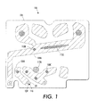
- FIG. 1 is a partial cross-sectional view of a print head housing containing multiple passages for ink
- FIG. 2 is a cross-sectional view of an ink manifold housing
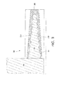
- FIG. 3 is a partial cross-sectional view of a print head including a tapered passage and portion of a reservoir
- FIG. 4 is a cross-sectional view of an ink reservoir configured to convey ink to one or more print heads.
- printer refers, for example, to reproduction devices in general, such as printers, facsimile machines, copiers, and related multi-function products. While the specification focuses on a system that controls the solidification process of phase-change ink in a printer, the system may be used with any phase-change ink image generation device. Solid ink may be called or referred to as ink, ink sticks, or sticks.
- via refers to any passage that conveys ink from one chamber to another chamber.
- the print head 100 has a housing 104, typically made of a metal, such as stainless steel or aluminum, or a polymer material. Within the housing 104 are one or more chambers that hold ink as exemplified by chambers 108A, 108B, and 108C. These chambers may be in fluid communication with one another through a passage not visible at the location of the cross-section. The chambers may have various shapes and sizes as determined by the requirements for ink flow through each print head 100. In the print head of FIG.
- thermal conductors 112A-C are disposed within and about the chambers 108A-C.
- Each thermal conductor 112 passes through housing 104 and connects to the exterior of the housing 104.
- the thermal conductors 112 act as temperature control connectors that control the rate of heat transfer from ink disposed within each chamber 108 to the exterior of housing 104.
- thermal conductor refers to a material having a relatively high coefficient of thermal conductivity, k, which enables heat to flow through the material across a temperature differential.
- the thermal conductors 112 are positioned so that the various regions of each chamber 108 have an approximately equal thermal mass.
- thermal conductor 112C bifurcates the surrounding ink channel in chamber 108A, forming two regions with roughly equivalent thermal masses.
- some or all of the thermal conductors 112 may connect to heat sinks (not shown) external to housing 104.
- the heat sinks are typically metallic plates that may optionally have metallic fins that aid in radiating conducted heat away from print head 100.
- thermal conductors may be of various shapes and sizes.
- thermal conductor 112A is cylindrical in shape, while thermal conductor 112B is also cylindrical with different diameter.
- Thermal conductors may also have a variety of shapes such as the oblique form of thermal conductor 112C.
- a thermal conductor may be placed proximate to an ink chamber such as thermal conductor 112A or placed within an ink reservoir as with thermal conductors 112B and 112C.
- the thermal conductors may be formed from various thermally conductive materials, with copper being one preferred material.
- the particular material used may be influenced by the desired thermal conductivity for each thermal conductor, so alternative print heads may use other materials with differing thermal conductivity including different metals or thermoplastics, and may employ thermal conductors formed of two or more materials in a single print head housing.
- the precise size, shape, and position of thermal conductors are selected to affect either the time needed for a thermal mass to solidify, the direction in which solidification takes place, or both. Because the ink affects heat distribution in the print head, appropriate selection and placement of thermal conductors help to control the temperature of the ink so the ink is more likely to cool and solidify without forming voids.
- Equation 1 the characteristic time for conduction for a thermal mass is expressed as the ratio of a characteristic dimension, L, to the thermal diffusivity, ⁇ , of the mass.
- the characteristic dimension, L, of the thermal mass is related to the volume to surface area ratio (V/A) of the thermal mass.
- V/A can be approximated by the radius or diameter, while for a cube it is the length of a side. Objects with large surface areas and small volumes have a small characteristic length for thermal conduction and cool much faster than objects with small surface areas and large volumes.
- the center of a sphere with radius 2R takes roughly 4 times as long to reach a given temperature than the center of a sphere of radius R.
- thermal conductors are placed in a manner that produces a desired t eff for each thermal mass of melted ink present in a print head.
- thermal conductors need to be positioned to enable an effective cooling length of the thermal mass to be the same as the smallest characteristic dimension in a passageway leading into or out of the chamber.
- the thermal conductors may be used to alter the volume to surface area ratio appropriately.
- a thermal conductor needs to provide a local temperature that enables a thicker mass to cool equivalently as a smaller mass experiencing a higher temperature gradient. In the embodiment of FIG.
- t eff time values for the ink in the portions of the print head near the print head's narrow vias 116 are shorter than the t eff time values in the chambers or the larger passages through the print head.
- the thermal conductors are positioned to equalize the thermal mass in the various portions of a chamber, to promote equalization of the time for the ink in the various portions of the print head 100 to solidify, or to encourage the freezing to occur in a direction that enables air bubbles or voids to be released from the solidifying ink.
- one or more vias 116 convey ink to and from the chambers 108 in the print head 100.
- the vias 116 in FIG. 1 have a shape that is wider at the opening 120 at one end of the via 116 and which tapers to a narrower opening 124 at the other end of the via.
- the direction of the taper is selected to control how ink in the via 116 solidifies as it cools.
- the taper acts as a different form of temperature control connector, allowing the ink in the via 116 to cool in a predictable manner.
- the preferred selection is for the narrow end of each via to be disposed towards the portion of the print head where ink should solidify first, since the narrower portions of the via 116 have a lower thermal mass of ink that is likely to solidify before the ink in the wider portions of the via.
- an ink manifold 200 includes an external housing 204 and reservoirs 208 that hold ink separately from one another.
- the manifold housing 204 is formed from a heat conductive material, such as a metal or a heat conductive thermoplastic.
- a heating element 212 acts as a heat source that heats ink stored in reservoirs 208.
- the heating element 212 is typically an electrically resistive heating element that may be selectively controlled to maintain a desired temperature within the manifold 200.
- the heating element allows for control over both the absolute temperature of the reservoirs and the rate of temperature change in the reservoirs 208. This control enables more uniform and directional solidification of the ink starting from the narrow vias 216 and proceeding to the larger reservoirs 208.
- an optional insulation layer 224 may also be placed around the housing 204.
- the insulation layer 224 reduces differences in the rate of heat escape from the thermally conductive housing 204, which leads to more uniform cooling.
- the insulation layer 224 operates as a temperature control connector that reduces "hot spots” and "cold spots” that could lead to ink solidifying in an uneven manner in the manifold reservoirs 208. While the insulation layer 224 depicted in FIG. 2 extends over the entire manifold housing 204, the insulation may also be placed over selected portions of the manifold housing 204 in order to achieve a uniform rate of heat conduction.
- FIG. 2 also contains vias 216 that convey ink from reservoirs 208 to other chambers in the print head.
- these vias have a shape that is wider at the opening 120 at one end of the via 116 and which tapers to a narrower opening 124 at the other end of the via.
- the direction of the taper is selected to control how ink in the via 216 solidifies as it cools.
- the taper acts as a different form of temperature control connector, allowing the ink in the via 216 to cool in a predictable manner.
- the preferred selection is for the narrow end of each via to be disposed towards the portion of the print head where ink should solidify first, since the narrower portions of the via 216 have a lower thermal mass of ink that solidifies prior to the wider portions of the via.
- FIG. 3 An example of a tapered via used in the embodiments of FIG. 1 and FIG. 2 is depicted in FIG. 3 .
- the via 300 has a wider opening 304 that tapers to a narrower opening 308.
- ink near the walls of the via solidify first forming solidifying fronts 312A and 312B.
- the tapered shape of the via means that the portions of ink proximate to the narrow opening 308 have a lower thermal mass and solidify more quickly. This shape enables directional solidification to start at the narrow opening 308 and move towards the wide opening 304.
- Some forms of ink contract as they solidify, which can cause voids to form if no liquid ink is present to fill the voids. If contraction occurs in the structure of FIG.
- the liquid ink in the reservoir 320 generates a positive back pressure that enables liquid ink to flow into the via 300 from the reservoir 320 to form a thermal mass 316 that fills voids between the solidified fronts 312A and 312B until the solidification process is complete. Because the reservoir 320 has a larger thermal mass than the narrow via 300, the ink held in the reservoir solidifies after ink the in via 300. Consequently, the reservoir 320 acts as a riser that provides additional liquid ink to fill any voids formed in via 300 during the solidification process.
- FIG. 4 An ink reservoir and ink conduit adapted to supply liquid ink to the print heads of FIG. 1 and FIG. 2 is depicted in FIG. 4 .
- the ink reservoir 404 holds ink 408 that may be solid or liquid depending upon the operational mode of the printer, with the example of FIG. 4 depicting solidified ink.
- the reservoir 404 is connected to print heads 420 using a tapered connector 416.
- the tapered connector 416 promotes directional solidification of ink from the narrow end proximate to print heads 420 to the wide end proximate to ink reservoir 404.
- the ink reservoir 404 holds a thermal mass that is larger than the thermal mass in the connector 416.
- the ink reservoir 404 acts as a positive pressure generating riser that enables ink to flow into the tapered connector 416 to fill voids that may occur in the solidifying fronts forming the connector 416. Consequently, the melted ink solidifies in a continuous mass free of voids or bubbles that rise to the surface of the mass inside the reservoir 404. If any bubbles form, they form within the larger reservoir 404 as shown at 412. In operation, bubbles in the reservoir 404 are eliminated when the solidified ink 408 is melted, preventing air bubbles from reaching the print heads 420.
Landscapes
- Ink Jet (AREA)
- Particle Formation And Scattering Control In Inkjet Printers (AREA)
Abstract
Description
- The devices and methods disclosed below generally relate to solid ink imaging devices, and, more particularly, to solid ink imaging devices that permit melted ink to solidify in a print head of the solid ink imaging device.
- Solid ink or phase change ink printers conventionally receive ink in a solid form, either as pellets or as ink sticks. The solid ink pellets or ink sticks are typically inserted through an insertion opening of an ink loader for the printer, and the ink sticks are pushed or slid along the feed channel by a feed mechanism and/or gravity toward a melt plate in the heater assembly. The melt plate melts the solid ink impinging on the plate into a liquid that is delivered to an ink reservoir which maintains the ink in melted form for delivery to a print head for jetting onto a recording medium.
- One difficulty faced during operation of solid ink printers is the electrical energy consumed by the printer. In particular electrical energy is required for the melting device to convert the solid ink to melted ink and print heads also require electrical energy to maintain the melted ink in the liquid phase. In an effort to conserve energy, solid ink printers are operated in various modes that consume different levels of energy. In these various modes, one or more components that include heaters to maintain melted ink in the liquid phase may be shut off to enable the melted ink to "freeze" or return to the solid state.
- One problem that arises from the freezing of melted ink is the formation of bubbles in the solidified ink. These entrapped bubbles must be purged when electrical energy is coupled to the components to liquefy the solidified ink. The purging operation, however, results in the discarding of ink from the printing system. Customers generally view the loss of ink as being undesirable. Thus, enabling the solidification of melted ink without the formation of entrapped bubbles in the solidified ink would be useful.
- An apparatus has been developed that enables melted ink in a print head to solidify with little or no formation of bubbles in the solidified ink. The apparatus includes a housing, a passage within the housing that is configured to store melted ink, and a temperature control connector mechanically coupled to the housing and passage, the temperature control connector being configured to mitigate void formation in melted ink as the melted ink cools in the passage.
- A print head has also been developed that enables melted ink in a reservoir of a print head to solidify with little or no formation of bubbles in the solidified ink. The print head includes a housing, a reservoir within the housing that is configured to store melted ink for ejection from the print head, and a thermal conductor that is thermally coupled to the melted ink within the reservoir to control solidification of the melted ink within the reservoir in response.
- The foregoing aspects and other features of the present disclosure are explained in the following description, taken in connection with the accompanying drawings.
-
FIG. 1 is a partial cross-sectional view of a print head housing containing multiple passages for ink; -
FIG. 2 is a cross-sectional view of an ink manifold housing; -
FIG. 3 is a partial cross-sectional view of a print head including a tapered passage and portion of a reservoir; and -
FIG. 4 is a cross-sectional view of an ink reservoir configured to convey ink to one or more print heads. - The term "printer" as used herein refers, for example, to reproduction devices in general, such as printers, facsimile machines, copiers, and related multi-function products. While the specification focuses on a system that controls the solidification process of phase-change ink in a printer, the system may be used with any phase-change ink image generation device. Solid ink may be called or referred to as ink, ink sticks, or sticks. The term "via" as used herein refers to any passage that conveys ink from one chamber to another chamber.
- An example of a print head housing that mitigates bubble formation in solidified ink held in the print head is depicted in the cross-sectional view of
FIG. 1 . Theprint head 100 has ahousing 104, typically made of a metal, such as stainless steel or aluminum, or a polymer material. Within thehousing 104 are one or more chambers that hold ink as exemplified bychambers print head 100. In the print head ofFIG. 1 , variousthermal conductors 112A-C are disposed within and about thechambers 108A-C. Each thermal conductor 112 passes throughhousing 104 and connects to the exterior of thehousing 104. The thermal conductors 112 act as temperature control connectors that control the rate of heat transfer from ink disposed within each chamber 108 to the exterior ofhousing 104. As used herein, thermal conductor refers to a material having a relatively high coefficient of thermal conductivity, k, which enables heat to flow through the material across a temperature differential. InFIG. 1 , the thermal conductors 112 are positioned so that the various regions of each chamber 108 have an approximately equal thermal mass. For example, thermal conductor 112C bifurcates the surrounding ink channel inchamber 108A, forming two regions with roughly equivalent thermal masses. Depending upon the desired rate of heat transfer, some or all of the thermal conductors 112 may connect to heat sinks (not shown) external to housing 104. The heat sinks are typically metallic plates that may optionally have metallic fins that aid in radiating conducted heat away fromprint head 100. - Depending upon the desired heat conduction characteristics, thermal conductors may be of various shapes and sizes. In
FIG. 1 ,thermal conductor 112A is cylindrical in shape, whilethermal conductor 112B is also cylindrical with different diameter. Thermal conductors may also have a variety of shapes such as the oblique form of thermal conductor 112C. A thermal conductor may be placed proximate to an ink chamber such asthermal conductor 112A or placed within an ink reservoir as withthermal conductors 112B and 112C. The thermal conductors may be formed from various thermally conductive materials, with copper being one preferred material. In designing the thermal conductors, the particular material used may be influenced by the desired thermal conductivity for each thermal conductor, so alternative print heads may use other materials with differing thermal conductivity including different metals or thermoplastics, and may employ thermal conductors formed of two or more materials in a single print head housing. The precise size, shape, and position of thermal conductors are selected to affect either the time needed for a thermal mass to solidify, the direction in which solidification takes place, or both. Because the ink affects heat distribution in the print head, appropriate selection and placement of thermal conductors help to control the temperature of the ink so the ink is more likely to cool and solidify without forming voids. - The following equation governs the characteristic time for conduction for a given thermal mass of ink:

In Equation 1, the characteristic time teff of thermal conduction for a thermal mass is expressed as the ratio of a characteristic dimension, L, to the thermal diffusivity, α, of the mass. The characteristic dimension, L, of the thermal mass is related to the volume to surface area ratio (V/A) of the thermal mass. For a sphere, V/A can be approximated by the radius or diameter, while for a cube it is the length of a side. Objects with large surface areas and small volumes have a small characteristic length for thermal conduction and cool much faster than objects with small surface areas and large volumes. As an example, the center of a sphere with radius 2R takes roughly 4 times as long to reach a given temperature than the center of a sphere of radius R. Although modifying the heat capacity or the thermal conductivity of the ink or surrounding material can also affect the time to change temperature, using thermal conductors to alter the volume to surface area ratio is a more effective way of controlling heat distribution in a print head due to the nonlinear relationship between conduction path length and thermal response time. - The thermal conductors are placed in a manner that produces a desired teff for each thermal mass of melted ink present in a print head. To be effective, thermal conductors need to be positioned to enable an effective cooling length of the thermal mass to be the same as the smallest characteristic dimension in a passageway leading into or out of the chamber. Likewise, as noted above, the thermal conductors may be used to alter the volume to surface area ratio appropriately. Alternatively, a thermal conductor needs to provide a local temperature that enables a thicker mass to cool equivalently as a smaller mass experiencing a higher temperature gradient. In the embodiment of
FIG. 1 , teff time values for the ink in the portions of the print head near the print head'snarrow vias 116 are shorter than the teff time values in the chambers or the larger passages through the print head. Thus, the thermal conductors are positioned to equalize the thermal mass in the various portions of a chamber, to promote equalization of the time for the ink in the various portions of theprint head 100 to solidify, or to encourage the freezing to occur in a direction that enables air bubbles or voids to be released from the solidifying ink. - Continuing to refer to
FIG. 1 , one ormore vias 116 convey ink to and from the chambers 108 in theprint head 100. Thevias 116 inFIG. 1 have a shape that is wider at the opening 120 at one end of thevia 116 and which tapers to anarrower opening 124 at the other end of the via. The direction of the taper is selected to control how ink in thevia 116 solidifies as it cools. The taper acts as a different form of temperature control connector, allowing the ink in thevia 116 to cool in a predictable manner. The preferred selection is for the narrow end of each via to be disposed towards the portion of the print head where ink should solidify first, since the narrower portions of thevia 116 have a lower thermal mass of ink that is likely to solidify before the ink in the wider portions of the via. - An alternative structure for controlling heat transfer within a print head is depicted in
FIG. 2 . InFIG. 2 , anink manifold 200 includes anexternal housing 204 andreservoirs 208 that hold ink separately from one another. Themanifold housing 204 is formed from a heat conductive material, such as a metal or a heat conductive thermoplastic. Aheating element 212 acts as a heat source that heats ink stored inreservoirs 208. Theheating element 212 is typically an electrically resistive heating element that may be selectively controlled to maintain a desired temperature within themanifold 200. The heating element allows for control over both the absolute temperature of the reservoirs and the rate of temperature change in thereservoirs 208. This control enables more uniform and directional solidification of the ink starting from thenarrow vias 216 and proceeding to thelarger reservoirs 208. - Again referring to
FIG. 2 , anoptional insulation layer 224 may also be placed around thehousing 204. Theinsulation layer 224 reduces differences in the rate of heat escape from the thermallyconductive housing 204, which leads to more uniform cooling. Theinsulation layer 224 operates as a temperature control connector that reduces "hot spots" and "cold spots" that could lead to ink solidifying in an uneven manner in themanifold reservoirs 208. While theinsulation layer 224 depicted inFIG. 2 extends over the entiremanifold housing 204, the insulation may also be placed over selected portions of themanifold housing 204 in order to achieve a uniform rate of heat conduction. -
FIG. 2 also containsvias 216 that convey ink fromreservoirs 208 to other chambers in the print head. As inFIG. 1 , these vias have a shape that is wider at theopening 120 at one end of the via 116 and which tapers to anarrower opening 124 at the other end of the via. The direction of the taper is selected to control how ink in the via 216 solidifies as it cools. The taper acts as a different form of temperature control connector, allowing the ink in the via 216 to cool in a predictable manner. The preferred selection is for the narrow end of each via to be disposed towards the portion of the print head where ink should solidify first, since the narrower portions of the via 216 have a lower thermal mass of ink that solidifies prior to the wider portions of the via. - An example of a tapered via used in the embodiments of
FIG. 1 andFIG. 2 is depicted inFIG. 3 . The via 300 has awider opening 304 that tapers to anarrower opening 308. In the example ofFIG. 3 , ink near the walls of the via solidify first forming solidifyingfronts narrow opening 308 have a lower thermal mass and solidify more quickly. This shape enables directional solidification to start at thenarrow opening 308 and move towards thewide opening 304. Some forms of ink contract as they solidify, which can cause voids to form if no liquid ink is present to fill the voids. If contraction occurs in the structure ofFIG. 3 , the liquid ink in thereservoir 320 generates a positive back pressure that enables liquid ink to flow into the via 300 from thereservoir 320 to form athermal mass 316 that fills voids between the solidifiedfronts reservoir 320 has a larger thermal mass than the narrow via 300, the ink held in the reservoir solidifies after ink the in via 300. Consequently, thereservoir 320 acts as a riser that provides additional liquid ink to fill any voids formed in via 300 during the solidification process. - An ink reservoir and ink conduit adapted to supply liquid ink to the print heads of
FIG. 1 andFIG. 2 is depicted inFIG. 4 . Theink reservoir 404 holdsink 408 that may be solid or liquid depending upon the operational mode of the printer, with the example ofFIG. 4 depicting solidified ink. Thereservoir 404 is connected to printheads 420 using a taperedconnector 416. In a similar manner to the via 300 depicted inFIG. 3 , the taperedconnector 416 promotes directional solidification of ink from the narrow end proximate to printheads 420 to the wide end proximate toink reservoir 404. Theink reservoir 404 holds a thermal mass that is larger than the thermal mass in theconnector 416. Thus, theink reservoir 404 acts as a positive pressure generating riser that enables ink to flow into the taperedconnector 416 to fill voids that may occur in the solidifying fronts forming theconnector 416. Consequently, the melted ink solidifies in a continuous mass free of voids or bubbles that rise to the surface of the mass inside thereservoir 404. If any bubbles form, they form within thelarger reservoir 404 as shown at 412. In operation, bubbles in thereservoir 404 are eliminated when the solidifiedink 408 is melted, preventing air bubbles from reaching the print heads 420.
Claims (10)
- A print head for ejecting melted ink onto an image receiving substrate comprising:a housing;a reservoir within the housing that is configured to store melted ink for ejection from the print head; anda thermal conductor that is thermally coupled to the melted ink within the reservoir to control solidification of the melted ink within the reservoir in response.
- The print head of claim 1, wherein the thermal conductor is mounted to an exterior of the housing at a position that enables the thermal conductor to dissipate heat from the melted ink within a portion of the reservoir.
- The print head of claim 1, wherein the thermal conductor extends through an exterior of the housing to a position proximate the reservoir.
- The print head of claim 1, wherein the thermal conductor extends through an exterior of the housing to a position within the reservoir.
- The print head of any of the preceding claims, further comprising:a heat sink mechanically connected to the thermal conductor to dissipate heat conducted by the thermal conductor from the melted ink within the reservoir.
- The print head of any of the preceding claims, further comprising:a thermal conductor mechanically connected to a heat source to enable heat to flow to the melted ink within the passage as the melted ink cools within the passage.
- The print head of any of the preceding claims, further comprising:a taper within a portion of a passage in the print head to control heat dissipation from melted ink within the passage.
- The print head of claim 1, wherein the thermal conductor is a passage and the heat source is a riser located within the housing of the print head.
- The print head of claim 8, further comprising:a taper within a portion of the passage in the print head to control heat dissipation from melted ink within the reservoir.
- The print head of any of the preceding claims, wherein the thermal conductor is mounted within the reservoir and positioned to divide the melted ink within a portion of the reservoir into approximately equal thermal masses.
Applications Claiming Priority (1)
| Application Number | Priority Date | Filing Date | Title |
|---|---|---|---|
| US12/714,031 US8419157B2 (en) | 2010-02-26 | 2010-02-26 | Apparatus for controlled freezing of melted solid ink in a solid ink printer |
Publications (3)
| Publication Number | Publication Date |
|---|---|
| EP2361769A2 true EP2361769A2 (en) | 2011-08-31 |
| EP2361769A3 EP2361769A3 (en) | 2012-02-29 |
| EP2361769B1 EP2361769B1 (en) | 2015-04-08 |
Family
ID=44148922
Family Applications (1)
| Application Number | Title | Priority Date | Filing Date |
|---|---|---|---|
| EP11154464.9A Not-in-force EP2361769B1 (en) | 2010-02-26 | 2011-02-15 | Apparatus for controlled freezing of melted solid ink in a solid ink printer |
Country Status (3)
| Country | Link |
|---|---|
| US (1) | US8419157B2 (en) |
| EP (1) | EP2361769B1 (en) |
| JP (1) | JP5829817B2 (en) |
Families Citing this family (1)
| Publication number | Priority date | Publication date | Assignee | Title |
|---|---|---|---|---|
| US9423188B2 (en) | 2013-12-23 | 2016-08-23 | Palo Alto Research Center Incorporated | Molded plastic objects having an integrated heat spreader and methods of manufacture of same |
Family Cites Families (39)
| Publication number | Priority date | Publication date | Assignee | Title |
|---|---|---|---|---|
| US3636605A (en) * | 1967-10-24 | 1972-01-25 | Trw Inc | Method of making forged valves from cast slugs |
| DE2543452C3 (en) * | 1975-09-29 | 1980-06-12 | Siemens Ag, 1000 Berlin Und 8000 Muenchen | Venting device for ink supply systems of inkjet writing devices |
| JPS5675867A (en) * | 1979-11-22 | 1981-06-23 | Seiko Epson Corp | Ink jet recorder |
| US4318437A (en) * | 1980-08-29 | 1982-03-09 | Kemp Willard E | Metal casting system |
| US4682644A (en) * | 1982-12-06 | 1987-07-28 | Kyocera Kabushiki Kaisha | Mold for use in dental precision casting |
| US4517577A (en) * | 1983-02-10 | 1985-05-14 | Exxon Research And Engineering Co. | Method of and apparatus for priming an ink jet |
| JPH0710597B2 (en) * | 1985-08-19 | 1995-02-08 | セイコーエプソン株式会社 | Inkjet recording device |
| JPS6273953A (en) * | 1985-09-27 | 1987-04-04 | Seiko Epson Corp | Head for inkjet printer |
| US4905752A (en) * | 1988-03-28 | 1990-03-06 | Pcc Airfoils, Inc. | Method of casting a metal article |
| US4998120A (en) * | 1988-04-06 | 1991-03-05 | Seiko Epson Corporation | Hot melt ink jet printing apparatus |
| US5172134A (en) | 1989-03-31 | 1992-12-15 | Canon Kabushiki Kaisha | Ink jet recording head, driving method for same and ink jet recording apparatus |
| US4981166A (en) * | 1989-06-27 | 1991-01-01 | Brown Foundry Systems, Inc. | Foundry paper riser and system therefor |
| US5205340A (en) * | 1989-06-27 | 1993-04-27 | Brown Foundry System, Inc. | Insulated paper sleeve for casting metal articles in sand molds |
| JPH03124841U (en) * | 1990-03-29 | 1991-12-18 | ||
| JPH05116279A (en) * | 1991-10-25 | 1993-05-14 | Canon Inc | Jet recording method |
| EP0571127A2 (en) | 1992-05-22 | 1993-11-24 | Hewlett-Packard Company | Monolithic thermal ink jet print head for phase-changing ink |
| US5757390A (en) * | 1992-08-12 | 1998-05-26 | Hewlett-Packard Company | Ink volume sensing and replenishing system |
| US5271451A (en) * | 1992-09-01 | 1993-12-21 | General Motors Corporation | Metal casting using a mold having attached risers |
| US5557305A (en) * | 1994-02-24 | 1996-09-17 | Spectra, Inc. | Ink jet purging arrangement |
| US5621444A (en) * | 1994-12-07 | 1997-04-15 | Hewlett-Packard Company | Controlled heating of solid ink in ink-jet printing |
| JP3212896B2 (en) * | 1996-12-02 | 2001-09-25 | シャープ株式会社 | Hot melt ink supply device |
| JPH10230623A (en) * | 1997-02-21 | 1998-09-02 | Hitachi Koki Co Ltd | Apparatus and method for removing bubbles from ink jet printer using heat-melt ink |
| US6196672B1 (en) * | 1997-06-27 | 2001-03-06 | Brother Kogyo Kabushiki Kaisha | Hot-melt type ink jet printer having heating and cooling arrangement |
| JP3840759B2 (en) * | 1997-08-29 | 2006-11-01 | ブラザー工業株式会社 | Inkjet head |
| US6176573B1 (en) * | 1999-11-15 | 2001-01-23 | Agilent Technologies Inc. | Gas-flow management using capillary capture and thermal release |
| US6257715B1 (en) * | 2000-03-07 | 2001-07-10 | Hewlett-Packard Company | Ink jet printer with ink conduit gas exhaust facility and method |
| US6530658B1 (en) * | 2000-05-30 | 2003-03-11 | Hewlett-Packard Company | Dispensing applicator and method of use |
| JP2004142328A (en) * | 2002-10-25 | 2004-05-20 | Canon Inc | Ink jet recording device using hot melt ink |
| AU2002952343A0 (en) * | 2002-10-30 | 2002-11-14 | Castalloy Manufacturing Pty Ltd | Apparatus and method for low pressure sand casting |
| US7144100B2 (en) * | 2004-01-07 | 2006-12-05 | Xerox Corporation | Purgeable print head reservoir |
| US7188941B2 (en) * | 2004-01-07 | 2007-03-13 | Xerox Corporation | Valve for a printing apparatus |
| US7413299B2 (en) * | 2005-03-15 | 2008-08-19 | Xerox Corporation | Pressurizing a heatable printhead while it cools |
| US7682008B2 (en) * | 2006-12-05 | 2010-03-23 | Xerox Corporation | Printhead reservoir with siphon vents |
| US7753512B2 (en) * | 2006-12-20 | 2010-07-13 | Xerox Corporation | System for maintaining temperature of a fluid in a conduit |
| US7568795B2 (en) | 2006-12-22 | 2009-08-04 | Xerox Corporation | Heated ink delivery system |
| US8070277B2 (en) * | 2007-07-05 | 2011-12-06 | Xerox Corporation | Ink-jet printer comprising a structure to eliminate ink dripping |
| US7815281B2 (en) * | 2007-09-07 | 2010-10-19 | Xerox Corporation | Print element de-prime method |
| US8052264B2 (en) * | 2008-03-26 | 2011-11-08 | Xerox Corporation | Melting device for increased production of melted ink in a solid ink printer |
| US8079691B2 (en) | 2009-02-09 | 2011-12-20 | Xerox Corporation | Foam plate for reducing foam in a printhead |
-
2010
- 2010-02-26 US US12/714,031 patent/US8419157B2/en not_active Expired - Fee Related
-
2011
- 2011-02-15 EP EP11154464.9A patent/EP2361769B1/en not_active Not-in-force
- 2011-02-21 JP JP2011034060A patent/JP5829817B2/en not_active Expired - Fee Related
Non-Patent Citations (1)
| Title |
|---|
| None |
Also Published As
| Publication number | Publication date |
|---|---|
| US20110211010A1 (en) | 2011-09-01 |
| EP2361769A3 (en) | 2012-02-29 |
| EP2361769B1 (en) | 2015-04-08 |
| JP2011178164A (en) | 2011-09-15 |
| JP5829817B2 (en) | 2015-12-09 |
| US8419157B2 (en) | 2013-04-16 |
Similar Documents
| Publication | Publication Date | Title |
|---|---|---|
| JP2832576B2 (en) | Temperature holding device and method | |
| US5784089A (en) | Melt plate design for a solid ink printer | |
| US8313183B2 (en) | Immersed high surface area heater for a solid ink reservoir | |
| KR101751072B1 (en) | Printer | |
| EP2484531B1 (en) | Pressure pulses to reduce bubbles and voids in phase change ink | |
| JP5280382B2 (en) | Reservoir assembly, heater and printer | |
| JP6463034B2 (en) | Liquid discharge head | |
| US20100194834A1 (en) | Ink Melt Device with Solid State Retention and Molten Ink Pass-Through | |
| BRPI1000343A2 (en) | foam board that reduces foam on a printhead | |
| EP2361769B1 (en) | Apparatus for controlled freezing of melted solid ink in a solid ink printer | |
| JPH0569541A (en) | Ink discharge device of ink-jet printer | |
| US20050179715A1 (en) | Systems for regulating temperature in fluid ejection devices | |
| AU2001279177B2 (en) | Determining minimum energy pulse characteristics in an ink jet print head | |
| EP2484529B1 (en) | Coordination of Pressure and Temperature During Ink Phase Change | |
| US8556372B2 (en) | Cooling rate and thermal gradient control to reduce bubbles and voids in phase change ink | |
| AU2001279177A1 (en) | Determining minimum energy pulse characteristics in an ink jet print head | |
| JP2011126277A (en) | Solid ink melting assembly | |
| EP2484528B1 (en) | Reduction of bubbles and voids in phase change ink | |
| JPH09156143A (en) | Image recording device | |
| KR20100036984A (en) | Melt reservoir housing | |
| JP3215633B2 (en) | Image recording device | |
| US8414116B2 (en) | Melt plate for use in a solid ink jet printer | |
| JPH0885203A (en) | Inkjet printer | |
| JPH03193457A (en) | ink supply device | |
| KR20070030614A (en) | Solid ink supply |
Legal Events
| Date | Code | Title | Description |
|---|---|---|---|
| PUAI | Public reference made under article 153(3) epc to a published international application that has entered the european phase |
Free format text: ORIGINAL CODE: 0009012 |
|
| AK | Designated contracting states |
Kind code of ref document: A2 Designated state(s): AL AT BE BG CH CY CZ DE DK EE ES FI FR GB GR HR HU IE IS IT LI LT LU LV MC MK MT NL NO PL PT RO RS SE SI SK SM TR |
|
| AX | Request for extension of the european patent |
Extension state: BA ME |
|
| PUAL | Search report despatched |
Free format text: ORIGINAL CODE: 0009013 |
|
| AK | Designated contracting states |
Kind code of ref document: A3 Designated state(s): AL AT BE BG CH CY CZ DE DK EE ES FI FR GB GR HR HU IE IS IT LI LT LU LV MC MK MT NL NO PL PT RO RS SE SI SK SM TR |
|
| AX | Request for extension of the european patent |
Extension state: BA ME |
|
| RIC1 | Information provided on ipc code assigned before grant |
Ipc: B41J 2/175 20060101AFI20120125BHEP |
|
| 17P | Request for examination filed |
Effective date: 20120829 |
|
| GRAP | Despatch of communication of intention to grant a patent |
Free format text: ORIGINAL CODE: EPIDOSNIGR1 |
|
| INTG | Intention to grant announced |
Effective date: 20141028 |
|
| GRAS | Grant fee paid |
Free format text: ORIGINAL CODE: EPIDOSNIGR3 |
|
| GRAA | (expected) grant |
Free format text: ORIGINAL CODE: 0009210 |
|
| AK | Designated contracting states |
Kind code of ref document: B1 Designated state(s): AL AT BE BG CH CY CZ DE DK EE ES FI FR GB GR HR HU IE IS IT LI LT LU LV MC MK MT NL NO PL PT RO RS SE SI SK SM TR |
|
| REG | Reference to a national code |
Ref country code: GB Ref legal event code: FG4D |
|
| REG | Reference to a national code |
Ref country code: CH Ref legal event code: EP |
|
| REG | Reference to a national code |
Ref country code: IE Ref legal event code: FG4D |
|
| REG | Reference to a national code |
Ref country code: AT Ref legal event code: REF Ref document number: 720217 Country of ref document: AT Kind code of ref document: T Effective date: 20150515 |
|
| REG | Reference to a national code |
Ref country code: DE Ref legal event code: R096 Ref document number: 602011015369 Country of ref document: DE Effective date: 20150521 |
|
| REG | Reference to a national code |
Ref country code: AT Ref legal event code: MK05 Ref document number: 720217 Country of ref document: AT Kind code of ref document: T Effective date: 20150408 |
|
| REG | Reference to a national code |
Ref country code: NL Ref legal event code: VDEP Effective date: 20150408 |
|
| REG | Reference to a national code |
Ref country code: LT Ref legal event code: MG4D |
|
| PG25 | Lapsed in a contracting state [announced via postgrant information from national office to epo] |
Ref country code: NL Free format text: LAPSE BECAUSE OF FAILURE TO SUBMIT A TRANSLATION OF THE DESCRIPTION OR TO PAY THE FEE WITHIN THE PRESCRIBED TIME-LIMIT Effective date: 20150408 |
|
| PG25 | Lapsed in a contracting state [announced via postgrant information from national office to epo] |
Ref country code: PT Free format text: LAPSE BECAUSE OF FAILURE TO SUBMIT A TRANSLATION OF THE DESCRIPTION OR TO PAY THE FEE WITHIN THE PRESCRIBED TIME-LIMIT Effective date: 20150810 Ref country code: LT Free format text: LAPSE BECAUSE OF FAILURE TO SUBMIT A TRANSLATION OF THE DESCRIPTION OR TO PAY THE FEE WITHIN THE PRESCRIBED TIME-LIMIT Effective date: 20150408 Ref country code: ES Free format text: LAPSE BECAUSE OF FAILURE TO SUBMIT A TRANSLATION OF THE DESCRIPTION OR TO PAY THE FEE WITHIN THE PRESCRIBED TIME-LIMIT Effective date: 20150408 Ref country code: HR Free format text: LAPSE BECAUSE OF FAILURE TO SUBMIT A TRANSLATION OF THE DESCRIPTION OR TO PAY THE FEE WITHIN THE PRESCRIBED TIME-LIMIT Effective date: 20150408 Ref country code: NO Free format text: LAPSE BECAUSE OF FAILURE TO SUBMIT A TRANSLATION OF THE DESCRIPTION OR TO PAY THE FEE WITHIN THE PRESCRIBED TIME-LIMIT Effective date: 20150708 Ref country code: FI Free format text: LAPSE BECAUSE OF FAILURE TO SUBMIT A TRANSLATION OF THE DESCRIPTION OR TO PAY THE FEE WITHIN THE PRESCRIBED TIME-LIMIT Effective date: 20150408 |
|
| PG25 | Lapsed in a contracting state [announced via postgrant information from national office to epo] |
Ref country code: LV Free format text: LAPSE BECAUSE OF FAILURE TO SUBMIT A TRANSLATION OF THE DESCRIPTION OR TO PAY THE FEE WITHIN THE PRESCRIBED TIME-LIMIT Effective date: 20150408 Ref country code: RS Free format text: LAPSE BECAUSE OF FAILURE TO SUBMIT A TRANSLATION OF THE DESCRIPTION OR TO PAY THE FEE WITHIN THE PRESCRIBED TIME-LIMIT Effective date: 20150408 Ref country code: IS Free format text: LAPSE BECAUSE OF FAILURE TO SUBMIT A TRANSLATION OF THE DESCRIPTION OR TO PAY THE FEE WITHIN THE PRESCRIBED TIME-LIMIT Effective date: 20150808 Ref country code: GR Free format text: LAPSE BECAUSE OF FAILURE TO SUBMIT A TRANSLATION OF THE DESCRIPTION OR TO PAY THE FEE WITHIN THE PRESCRIBED TIME-LIMIT Effective date: 20150709 Ref country code: AT Free format text: LAPSE BECAUSE OF FAILURE TO SUBMIT A TRANSLATION OF THE DESCRIPTION OR TO PAY THE FEE WITHIN THE PRESCRIBED TIME-LIMIT Effective date: 20150408 |
|
| REG | Reference to a national code |
Ref country code: DE Ref legal event code: R097 Ref document number: 602011015369 Country of ref document: DE |
|
| REG | Reference to a national code |
Ref country code: FR Ref legal event code: PLFP Year of fee payment: 6 |
|
| PG25 | Lapsed in a contracting state [announced via postgrant information from national office to epo] |
Ref country code: EE Free format text: LAPSE BECAUSE OF FAILURE TO SUBMIT A TRANSLATION OF THE DESCRIPTION OR TO PAY THE FEE WITHIN THE PRESCRIBED TIME-LIMIT Effective date: 20150408 Ref country code: DK Free format text: LAPSE BECAUSE OF FAILURE TO SUBMIT A TRANSLATION OF THE DESCRIPTION OR TO PAY THE FEE WITHIN THE PRESCRIBED TIME-LIMIT Effective date: 20150408 |
|
| PLBE | No opposition filed within time limit |
Free format text: ORIGINAL CODE: 0009261 |
|
| STAA | Information on the status of an ep patent application or granted ep patent |
Free format text: STATUS: NO OPPOSITION FILED WITHIN TIME LIMIT |
|
| PG25 | Lapsed in a contracting state [announced via postgrant information from national office to epo] |
Ref country code: CZ Free format text: LAPSE BECAUSE OF FAILURE TO SUBMIT A TRANSLATION OF THE DESCRIPTION OR TO PAY THE FEE WITHIN THE PRESCRIBED TIME-LIMIT Effective date: 20150408 Ref country code: SK Free format text: LAPSE BECAUSE OF FAILURE TO SUBMIT A TRANSLATION OF THE DESCRIPTION OR TO PAY THE FEE WITHIN THE PRESCRIBED TIME-LIMIT Effective date: 20150408 Ref country code: RO Free format text: LAPSE BECAUSE OF NON-PAYMENT OF DUE FEES Effective date: 20150408 Ref country code: PL Free format text: LAPSE BECAUSE OF FAILURE TO SUBMIT A TRANSLATION OF THE DESCRIPTION OR TO PAY THE FEE WITHIN THE PRESCRIBED TIME-LIMIT Effective date: 20150408 |
|
| 26N | No opposition filed |
Effective date: 20160111 |
|
| PG25 | Lapsed in a contracting state [announced via postgrant information from national office to epo] |
Ref country code: IT Free format text: LAPSE BECAUSE OF FAILURE TO SUBMIT A TRANSLATION OF THE DESCRIPTION OR TO PAY THE FEE WITHIN THE PRESCRIBED TIME-LIMIT Effective date: 20150408 |
|
| PG25 | Lapsed in a contracting state [announced via postgrant information from national office to epo] |
Ref country code: BE Free format text: LAPSE BECAUSE OF NON-PAYMENT OF DUE FEES Effective date: 20160229 Ref country code: SI Free format text: LAPSE BECAUSE OF FAILURE TO SUBMIT A TRANSLATION OF THE DESCRIPTION OR TO PAY THE FEE WITHIN THE PRESCRIBED TIME-LIMIT Effective date: 20150408 |
|
| PG25 | Lapsed in a contracting state [announced via postgrant information from national office to epo] |
Ref country code: BE Free format text: LAPSE BECAUSE OF FAILURE TO SUBMIT A TRANSLATION OF THE DESCRIPTION OR TO PAY THE FEE WITHIN THE PRESCRIBED TIME-LIMIT Effective date: 20150408 |
|
| PG25 | Lapsed in a contracting state [announced via postgrant information from national office to epo] |
Ref country code: LU Free format text: LAPSE BECAUSE OF FAILURE TO SUBMIT A TRANSLATION OF THE DESCRIPTION OR TO PAY THE FEE WITHIN THE PRESCRIBED TIME-LIMIT Effective date: 20160215 Ref country code: MC Free format text: LAPSE BECAUSE OF FAILURE TO SUBMIT A TRANSLATION OF THE DESCRIPTION OR TO PAY THE FEE WITHIN THE PRESCRIBED TIME-LIMIT Effective date: 20150408 |
|
| REG | Reference to a national code |
Ref country code: CH Ref legal event code: PL |
|
| PG25 | Lapsed in a contracting state [announced via postgrant information from national office to epo] |
Ref country code: CH Free format text: LAPSE BECAUSE OF NON-PAYMENT OF DUE FEES Effective date: 20160229 Ref country code: LI Free format text: LAPSE BECAUSE OF NON-PAYMENT OF DUE FEES Effective date: 20160229 |
|
| REG | Reference to a national code |
Ref country code: IE Ref legal event code: MM4A |
|
| REG | Reference to a national code |
Ref country code: FR Ref legal event code: PLFP Year of fee payment: 7 |
|
| PG25 | Lapsed in a contracting state [announced via postgrant information from national office to epo] |
Ref country code: IE Free format text: LAPSE BECAUSE OF NON-PAYMENT OF DUE FEES Effective date: 20160215 |
|
| PGFP | Annual fee paid to national office [announced via postgrant information from national office to epo] |
Ref country code: DE Payment date: 20170119 Year of fee payment: 7 Ref country code: FR Payment date: 20170124 Year of fee payment: 7 |
|
| PGFP | Annual fee paid to national office [announced via postgrant information from national office to epo] |
Ref country code: GB Payment date: 20170124 Year of fee payment: 7 |
|
| PG25 | Lapsed in a contracting state [announced via postgrant information from national office to epo] |
Ref country code: SE Free format text: LAPSE BECAUSE OF FAILURE TO SUBMIT A TRANSLATION OF THE DESCRIPTION OR TO PAY THE FEE WITHIN THE PRESCRIBED TIME-LIMIT Effective date: 20150408 |
|
| PG25 | Lapsed in a contracting state [announced via postgrant information from national office to epo] |
Ref country code: MT Free format text: LAPSE BECAUSE OF FAILURE TO SUBMIT A TRANSLATION OF THE DESCRIPTION OR TO PAY THE FEE WITHIN THE PRESCRIBED TIME-LIMIT Effective date: 20150408 |
|
| PG25 | Lapsed in a contracting state [announced via postgrant information from national office to epo] |
Ref country code: CY Free format text: LAPSE BECAUSE OF FAILURE TO SUBMIT A TRANSLATION OF THE DESCRIPTION OR TO PAY THE FEE WITHIN THE PRESCRIBED TIME-LIMIT Effective date: 20150408 Ref country code: SM Free format text: LAPSE BECAUSE OF FAILURE TO SUBMIT A TRANSLATION OF THE DESCRIPTION OR TO PAY THE FEE WITHIN THE PRESCRIBED TIME-LIMIT Effective date: 20150408 Ref country code: HU Free format text: LAPSE BECAUSE OF FAILURE TO SUBMIT A TRANSLATION OF THE DESCRIPTION OR TO PAY THE FEE WITHIN THE PRESCRIBED TIME-LIMIT; INVALID AB INITIO Effective date: 20110215 |
|
| PG25 | Lapsed in a contracting state [announced via postgrant information from national office to epo] |
Ref country code: MT Free format text: LAPSE BECAUSE OF FAILURE TO SUBMIT A TRANSLATION OF THE DESCRIPTION OR TO PAY THE FEE WITHIN THE PRESCRIBED TIME-LIMIT Effective date: 20160229 Ref country code: TR Free format text: LAPSE BECAUSE OF FAILURE TO SUBMIT A TRANSLATION OF THE DESCRIPTION OR TO PAY THE FEE WITHIN THE PRESCRIBED TIME-LIMIT Effective date: 20150408 Ref country code: MK Free format text: LAPSE BECAUSE OF FAILURE TO SUBMIT A TRANSLATION OF THE DESCRIPTION OR TO PAY THE FEE WITHIN THE PRESCRIBED TIME-LIMIT Effective date: 20150408 |
|
| PG25 | Lapsed in a contracting state [announced via postgrant information from national office to epo] |
Ref country code: BG Free format text: LAPSE BECAUSE OF FAILURE TO SUBMIT A TRANSLATION OF THE DESCRIPTION OR TO PAY THE FEE WITHIN THE PRESCRIBED TIME-LIMIT Effective date: 20150408 |
|
| REG | Reference to a national code |
Ref country code: DE Ref legal event code: R119 Ref document number: 602011015369 Country of ref document: DE |
|
| GBPC | Gb: european patent ceased through non-payment of renewal fee |
Effective date: 20180215 |
|
| PG25 | Lapsed in a contracting state [announced via postgrant information from national office to epo] |
Ref country code: AL Free format text: LAPSE BECAUSE OF FAILURE TO SUBMIT A TRANSLATION OF THE DESCRIPTION OR TO PAY THE FEE WITHIN THE PRESCRIBED TIME-LIMIT Effective date: 20150408 |
|
| REG | Reference to a national code |
Ref country code: FR Ref legal event code: ST Effective date: 20181031 |
|
| PG25 | Lapsed in a contracting state [announced via postgrant information from national office to epo] |
Ref country code: DE Free format text: LAPSE BECAUSE OF NON-PAYMENT OF DUE FEES Effective date: 20180901 |
|
| PG25 | Lapsed in a contracting state [announced via postgrant information from national office to epo] |
Ref country code: FR Free format text: LAPSE BECAUSE OF NON-PAYMENT OF DUE FEES Effective date: 20180228 Ref country code: GB Free format text: LAPSE BECAUSE OF NON-PAYMENT OF DUE FEES Effective date: 20180215 |