EP2361721B1 - Method and apparatus for assembling of coils for exchangers - Google Patents
Method and apparatus for assembling of coils for exchangers Download PDFInfo
- Publication number
- EP2361721B1 EP2361721B1 EP20110155380 EP11155380A EP2361721B1 EP 2361721 B1 EP2361721 B1 EP 2361721B1 EP 20110155380 EP20110155380 EP 20110155380 EP 11155380 A EP11155380 A EP 11155380A EP 2361721 B1 EP2361721 B1 EP 2361721B1
- Authority
- EP
- European Patent Office
- Prior art keywords
- support zone
- coils
- coil
- axis
- motorized
- Prior art date
- Legal status (The legal status is an assumption and is not a legal conclusion. Google has not performed a legal analysis and makes no representation as to the accuracy of the status listed.)
- Active
Links
Images

Classifications
-
- B—PERFORMING OPERATIONS; TRANSPORTING
- B23—MACHINE TOOLS; METAL-WORKING NOT OTHERWISE PROVIDED FOR
- B23P—METAL-WORKING NOT OTHERWISE PROVIDED FOR; COMBINED OPERATIONS; UNIVERSAL MACHINE TOOLS
- B23P15/00—Making specific metal objects by operations not covered by a single other subclass or a group in this subclass
- B23P15/26—Making specific metal objects by operations not covered by a single other subclass or a group in this subclass heat exchangers or the like
-
- F—MECHANICAL ENGINEERING; LIGHTING; HEATING; WEAPONS; BLASTING
- F28—HEAT EXCHANGE IN GENERAL
- F28D—HEAT-EXCHANGE APPARATUS, NOT PROVIDED FOR IN ANOTHER SUBCLASS, IN WHICH THE HEAT-EXCHANGE MEDIA DO NOT COME INTO DIRECT CONTACT
- F28D7/00—Heat-exchange apparatus having stationary tubular conduit assemblies for both heat-exchange media, the media being in contact with different sides of a conduit wall
- F28D7/02—Heat-exchange apparatus having stationary tubular conduit assemblies for both heat-exchange media, the media being in contact with different sides of a conduit wall the conduits being helically coiled
- F28D7/024—Heat-exchange apparatus having stationary tubular conduit assemblies for both heat-exchange media, the media being in contact with different sides of a conduit wall the conduits being helically coiled the conduits of only one medium being helically coiled tubes, the coils having a cylindrical configuration
Definitions
- the present invention relates to an innovative method and to an apparatus for assembling coils for exchangers.
- heat exchangers formed with a plurality of coils which are each wound in the manner of a cylindrical spiral and which, being made with an increasingly larger diameter, are inserted axially on top of each other so as to form an exchange unit.
- Large-size exchangers (for example for chemical plants), which may also have a length greater than ten or so metres and a diameter of more than three metres, may comprise several tens of such helical coils inserted inside one another and suitably connected together. The entire set of coils thus forms a cylindrical structure of exchange tubes which is enclosed inside a pressure container to form the complete exchanger.
- a main problem in the manufacture of these exchangers is assembly of the coils.
- the coils are introduced substantially manually inside one another with the aid solely of raising systems. This operation is long, laborious and complex.
- a further complication consists in the fact that, in order to maintain the mechanical stability of the coils, the exchanger is provided with radial baffles having holes through which each turn of each coil must pass. During the assembly operations it is easy to cause deformation of the spirals, making it even more difficult or even impossible to insert the spirals into the baffles.
- JP 8327256 discloses a method for assembling on an apparatus spiral coils for exchangers.
- US 3 646 599 discloses an apparatus and a method for winding coiled tube banks.
- the main object of the present invention is to provide a method and an apparatus which are able to facilitate the operations of assembly of the coils for forming the exchange unit.
- Figure 1 shows an apparatus - denoted generally by 10 - designed according to the invention for the assembly of exchange units formed by cylindrical-spiral coils 32 arranged concentrically.
- These exchange units are of the known type, suitable for forming corresponding known fluid-type heat exchangers, for example for chemical plants.
- the apparatus operates with the coils arranged with their axis in the horizontal position.
- the apparatus 10 comprises a support zone 11 which is intended to receive the spiral coils arranged concentrically on each other, as will become clear below.
- An insertion device 12 is intended to insert one at a time the spiral coils towards the support zone 11, while the motorized roller means 13, which are present on the sides and along the support zone 11, cause axial rotation of the spiral coil during insertion thereof into the support zone, so as to obtain a combined screwing movement towards the support zone and above the spiral coils which may have already been inserted into the support zone.
- the insertion device 12 of the apparatus comprises guides 14 for supporting and sliding of the coil to be inserted and means 15 for moving the guides in the vertical direction so as to move the axis of the coil being inserted towards the axis of the unit being assembled and, in the specific case, towards the axis of the coils which are already present in the support zone.
- the movement (which may also be inclined) may result in alignment of the axes or, taking advantage of the flexibility of the spirals, stop beforehand.
- the sliding guides comprise two support rollers with a motorized axis of rotation which is parallel to the axis of insertion of the coil so as to support the coil and impart to it an axial rotational movement during insertion.
- the movement means 15 are advantageously formed with motorized pantograph raising devices on which the sliding guides or rollers 14 rest.
- the support zone 11 is bounded by a frame of the apparatus which supports the motorized rotational roller means on the sides of the support zone.
- these roller means comprise advantageously at least two roller elements 13 arranged facing on two opposite sides of the support zone and with the motorized axis of rotation which is parallel to the axis of the spiral coils in the support zone 11.
- rollers 13 extend advantageously along the entire support zone 11 of the apparatus, which is bounded by facing plate-like end shoulders 17, 18 which are generally U-shaped.
- Each roller element 13 performs a controlled transverse approach movement towards the axis of rotation of the coils in the support zone, so as to adapt to the diameter of the specific coil being inserted, resting peripherally against it so as to transmit to it the motorized axial-rotation movement.
- the motorized rollers 13 comprise advantageously a plurality of grooved wheels 16 which are spaced along the support zone and which are intended to rest against the turns of the spiral coil so as to guide it during the rotating and advancing movement.
- each motorized roller 13 is supported at the ends by corresponding actuating systems 19, 20 and 21, 22 which perform a controlled synchronized horizontal movement.
- the movement of the rollers is advantageously radial to the spiral coil in the support zone.
- the support zone is provided with supports for radial baffles 24 with holes, through which the front end of the coil is intended to pass gradually during its rotational insertion movement.
- the baffles are, for example, screwed to the supports.
- the radial baffles have a shape which depends on the structure of the exchanger being assembled, as can be easily imagined by the person skilled in the art.
- these baffles are formed by radial metal plates of suitable thickness which extend along generatrices of the cylinder of the exchange unit and which are provided with a plurality of holes arranged in the manner of a grid which depends on both the axial and radial pitch which the spirals of the coils in the exchanger must have.
- the baffles are six in number, being arranged at angles of 60° around the axis of the exchange unit to be assembled.
- the number may obviously vary depending on specific constructional requirements of the exchanger.
- the supports 23 comprise support arms 26, 27 which project at intervals from beams arranged between the end shoulders 17 and 18 of the apparatus.
- the supports for the baffles also comprise central Y-shaped elements 25 which co-operate with at least a first series of peripheral radial arms 26 supporting a first series of three radial baffles arranged at 120°.
- the central support 25 is intended to be disassembled after complete formation and extraction of the assembled unit.
- the supports for the baffles also comprise further peripheral radial arms 27 for a second series of three radial baffles arranged alternating with the first series of baffles in the circumferential direction about the axis of rotation of the coils in the support zone.
- Figure 5 shows schematically the support zone 11 of the apparatus with an exchange unit 30 formed by a plurality of spiral coils which have already been passed through the radial baffles.
- the apparatus may also advantageously comprise motorized vibration devices.
- These devices (which are substantially known from the prior art and are schematically indicated by 29 in Figure 4 ) have the function of causing vibration of the coils which are in the support zone and/or being inserted into the support zone by the insertion device 12.
- the use of a vibration during insertion has been found to be particularly advantageous for reducing the friction and facilitating sliding of the new coil through the holes present in the radial baffles.
- the coils are rested one at a time on the insertion device 12, starting with the smaller-diameter coil and are fed one at a time towards the support zone.
- the coils are rotated axially by motorized means. There is thus a combined "screwing" movement within the support zone and above the spiral coils already introduced into the support zone.
- the rotational rollers are displaced radially so as to adapt to the diameter of the new coil, while the insertion device is displaced so as to align suitably the axis of the new coil with the unit in the support zone.
- each spiral may also be initially guided manually inside the holes of the baffle, during the slow rotation of the spiral.
- the coils present in the support zone and/or being rotationally inserted into the support zone are made to vibrate.
- FIG. 6 shows schematically the exchange unit 30 completed and inserted into the pressure container 31 which enclosed the exchanger unit.
- Suitable connection pipes for providing an outlet in a direction parallel to the axial direction of the unit are welded to the ends of the coils.
- These connection elements are in turn welded to the plates (not shown) in suitable inlet zones for the fluid which must pass through the coils.
- the heat exchanger 33 is thus formed.
- the vibrating means may also be movable so as to be arranged in different positions depending on the specific needs.
- the baffles may also have different dimensions as shown.
- the intermediate baffles may be shorter and not reach the innermost coils, as shown in Figure 5 .
Description
- The present invention relates to an innovative method and to an apparatus for assembling coils for exchangers.
- Already known from the prior art are heat exchangers formed with a plurality of coils which are each wound in the manner of a cylindrical spiral and which, being made with an increasingly larger diameter, are inserted axially on top of each other so as to form an exchange unit.
- Large-size exchangers (for example for chemical plants), which may also have a length greater than ten or so metres and a diameter of more than three metres, may comprise several tens of such helical coils inserted inside one another and suitably connected together. The entire set of coils thus forms a cylindrical structure of exchange tubes which is enclosed inside a pressure container to form the complete exchanger.
- A main problem in the manufacture of these exchangers is assembly of the coils. Usually, after producing the single helical coils by means of a suitable spiralling apparatus, the coils are introduced substantially manually inside one another with the aid solely of raising systems. This operation is long, laborious and complex.
- A further complication consists in the fact that, in order to maintain the mechanical stability of the coils, the exchanger is provided with radial baffles having holes through which each turn of each coil must pass. During the assembly operations it is easy to cause deformation of the spirals, making it even more difficult or even impossible to insert the spirals into the baffles.
-
JP 8327256 -
US 3 646 599 discloses an apparatus and a method for winding coiled tube banks. - The main object of the present invention is to provide a method and an apparatus which are able to facilitate the operations of assembly of the coils for forming the exchange unit.
- This object is achieved by the features of the independent claims of the present application. Preferred embodiments are presented in the dependent claims.
- In order to illustrate more clearly the innovative principles of the present invention and its advantages compared to the prior art, an example of embodiment applying these principles will be described below, with the aid of the accompanying drawings. In the drawings:
-
Figure 1 shows a schematic perspective view of an apparatus provided according to the invention; -
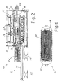
Figure 2 shows a side elevation view of the apparatus according toFigure 1 during insertion of a coil; -
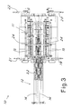
Figure 3 shows a plan view of the apparatus according toFigure 1 during insertion of a coil; -
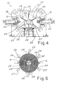
Figure 4 shows a view from one end of the apparatus according toFigure 1 ; -
Figure 5 shows a schematic view from one end of the assembly zone with an exchange unit nearly completed; -
Figure 6 shows a schematic and partial view of an exchanger unit assembled with the apparatus according toFigure 1 . - With reference to the figures,
Figure 1 shows an apparatus - denoted generally by 10 - designed according to the invention for the assembly of exchange units formed by cylindrical-spiral coils 32 arranged concentrically. These exchange units are of the known type, suitable for forming corresponding known fluid-type heat exchangers, for example for chemical plants. Advantageously, the apparatus operates with the coils arranged with their axis in the horizontal position. - The
apparatus 10 comprises asupport zone 11 which is intended to receive the spiral coils arranged concentrically on each other, as will become clear below. Aninsertion device 12 is intended to insert one at a time the spiral coils towards thesupport zone 11, while the motorized roller means 13, which are present on the sides and along thesupport zone 11, cause axial rotation of the spiral coil during insertion thereof into the support zone, so as to obtain a combined screwing movement towards the support zone and above the spiral coils which may have already been inserted into the support zone. As can be clearly seen inFigure 2 , theinsertion device 12 of the apparatus comprisesguides 14 for supporting and sliding of the coil to be inserted and means 15 for moving the guides in the vertical direction so as to move the axis of the coil being inserted towards the axis of the unit being assembled and, in the specific case, towards the axis of the coils which are already present in the support zone. The movement (which may also be inclined) may result in alignment of the axes or, taking advantage of the flexibility of the spirals, stop beforehand. - Advantageously, the sliding guides, comprise two support rollers with a motorized axis of rotation which is parallel to the axis of insertion of the coil so as to support the coil and impart to it an axial rotational movement during insertion.
- The movement means 15 are advantageously formed with motorized pantograph raising devices on which the sliding guides or
rollers 14 rest. - The
support zone 11 is bounded by a frame of the apparatus which supports the motorized rotational roller means on the sides of the support zone. - As can be clearly seen also in
Figures 3 and4 , these roller means comprise advantageously at least tworoller elements 13 arranged facing on two opposite sides of the support zone and with the motorized axis of rotation which is parallel to the axis of the spiral coils in thesupport zone 11. - The
rollers 13 extend advantageously along theentire support zone 11 of the apparatus, which is bounded by facing plate-like end shoulders - Each
roller element 13 performs a controlled transverse approach movement towards the axis of rotation of the coils in the support zone, so as to adapt to the diameter of the specific coil being inserted, resting peripherally against it so as to transmit to it the motorized axial-rotation movement. As can be seen also inFigure 2 , the motorizedrollers 13 comprise advantageously a plurality ofgrooved wheels 16 which are spaced along the support zone and which are intended to rest against the turns of the spiral coil so as to guide it during the rotating and advancing movement. - Advantageously, for the transverse movement of the motorized rollers, each motorized
roller 13 is supported at the ends bycorresponding actuating systems - The movement of the rollers is advantageously radial to the spiral coil in the support zone.
- As can be clearly seen in
Figure 4 , advantageously the transverse movement of the rollers is performed in a horizontal plane which passes through the axis of rotation of the spirals. This axis also coincides with the axis of the exchange unit which is assembled. - As can be clearly seen also in
Figure 4 , the support zone is provided with supports forradial baffles 24 with holes, through which the front end of the coil is intended to pass gradually during its rotational insertion movement. The baffles are, for example, screwed to the supports. - The radial baffles have a shape which depends on the structure of the exchanger being assembled, as can be easily imagined by the person skilled in the art.
- As can be clearly seen in
Figure 1 , usually these baffles are formed by radial metal plates of suitable thickness which extend along generatrices of the cylinder of the exchange unit and which are provided with a plurality of holes arranged in the manner of a grid which depends on both the axial and radial pitch which the spirals of the coils in the exchanger must have. - In the embodiment shown, the baffles are six in number, being arranged at angles of 60° around the axis of the exchange unit to be assembled. The number may obviously vary depending on specific constructional requirements of the exchanger.
- The
supports 23 comprisesupport arms end shoulders - Advantageously, the supports for the baffles also comprise central Y-
shaped elements 25 which co-operate with at least a first series of peripheralradial arms 26 supporting a first series of three radial baffles arranged at 120°. In this way there is a greater rigidity in the positioning of these baffles and the insertion of the coil by means of axial rotation is facilitated. Thecentral support 25 is intended to be disassembled after complete formation and extraction of the assembled unit. - Advantageously, the supports for the baffles also comprise further peripheral
radial arms 27 for a second series of three radial baffles arranged alternating with the first series of baffles in the circumferential direction about the axis of rotation of the coils in the support zone. -
Figure 5 shows schematically thesupport zone 11 of the apparatus with anexchange unit 30 formed by a plurality of spiral coils which have already been passed through the radial baffles. - In order to facilitate the insertion operation, the apparatus may also advantageously comprise motorized vibration devices. These devices (which are substantially known from the prior art and are schematically indicated by 29 in
Figure 4 ) have the function of causing vibration of the coils which are in the support zone and/or being inserted into the support zone by theinsertion device 12. The use of a vibration during insertion has been found to be particularly advantageous for reducing the friction and facilitating sliding of the new coil through the holes present in the radial baffles. - During use of the apparatus (once the coils wound with a suitable diameter by means of known spiralling machines from tubes have been prepared) the coils are rested one at a time on the
insertion device 12, starting with the smaller-diameter coil and are fed one at a time towards the support zone. During insertion of the coil into the support zone it is rotated axially by motorized means. There is thus a combined "screwing" movement within the support zone and above the spiral coils already introduced into the support zone. - With each change of coil, the rotational rollers are displaced radially so as to adapt to the diameter of the new coil, while the insertion device is displaced so as to align suitably the axis of the new coil with the unit in the support zone.
- The front end of each spiral may also be initially guided manually inside the holes of the baffle, during the slow rotation of the spiral.
- Advantageously, during insertion, the coils present in the support zone and/or being rotationally inserted into the support zone are made to vibrate.
- The procedure is repeated until all the coils have been assembled on one another so as to complete the
exchange unit 30. After this, the radial baffles are disconnected from the supports and the entire unit may be extracted from the machine and the following steps for assembly with the remaining parts of the exchanger are started. -
Figure 6 shows schematically theexchange unit 30 completed and inserted into thepressure container 31 which enclosed the exchanger unit. Suitable connection pipes for providing an outlet in a direction parallel to the axial direction of the unit are welded to the ends of the coils. These connection elements are in turn welded to the plates (not shown) in suitable inlet zones for the fluid which must pass through the coils. Theheat exchanger 33 is thus formed. - The exact structure of the exchanger will obviously depend on the specific requirements and therefore is not shown, it being able to be easily imagined by the person skilled in the art.
- At this point it is clear how the predefined objects have been achieved. With the assembly apparatus and method described it is possible to assemble in a rapid and precise manner the coils of an exchanger with superimposed spiral coils.
- Obviously, the above description of an embodiment applying the innovative principles of the present invention is provided by way of example of these innovative principles and must therefore not be regarded as limiting the scope of the rights claimed herein. For example the proportions of the various parts and the exact structure of the supports may vary depending on the particular exchanger being assembled, also considering that an assembly apparatus and method according to the invention allow assembly, without difficulty, of exchanger coils which may also be of considerable size and weight, for example also with a length greater than ten or so metres and a diameter of more than three metres.
- The vibrating means may also be movable so as to be arranged in different positions depending on the specific needs.
- The baffles may also have different dimensions as shown. For example, the intermediate baffles may be shorter and not reach the innermost coils, as shown in
Figure 5 .
Claims (13)
- Apparatus (10) for assembling concentric spiral coils for exchangers, comprising a support zone (11) which is intended to receive the spiral coils (32) arranged concentrically on top of each other, an insertion device (12) which inserts one at a time the spiral coils towards the support zone (11), and motorized roller means (13) for axial peripheral rotation of the spiral coil during insertion thereof into the support zone (11) for a combined screwing movement within the support zone and above the spiral coils already inserted into the support zone.
- Apparatus according to Claim 1, characterized in that the motorized roller means comprise at least two roller elements (13) with a motorized axis of rotation which is parallel to the axis of the spiral coils in the support zone, each roller element (13) having means (19, 20, 21, 22) for performing a controlled approach movement towards the axis of rotation of the coils in the support zone (11) so as to adapt to the diameter of the coil being inserted, resting peripherally against it and transmitting to it the motorized axial-rotation movement.
- Apparatus according to Claim 2, characterized in that the roller elements (13) comprises grooved wheels (16) which are spaced along the support zone and intended to rest against the turns of the spiral coils to be rotated.
- Apparatus according to Claim 2, characterized in that the approach movement of the roller elements (13) is horizontal and radial to the coil in the support zone (11).
- Apparatus according to Claim 1, characterized in that the coils are supported and rotated with their axis horizontal.
- Apparatus according to Claim 1, characterized in that the insertion device (12) comprises guides (14) for supporting and sliding of the coil to be inserted and means (15) for moving the guides in the vertical direction so as to allow the axis of the coil being inserted to be moved towards the axis of the coils in the support zone.
- Apparatus according to Claim 6, characterized in that sliding guides are support rollers (14) with a motorized axis of rotation which is parallel to the axis of insertion of the coil.
- Apparatus according to Claim 1, characterized in that the support zone (11) comprises motorized vibrating devices (29) for causing vibration of the coils (32) present in this zone and/or being inserted into this zone (11).
- Apparatus according to Claim 1, characterized in that the support zone (11) is provided with supports (23, 25, 26, 27) for supporting radial baffles (24) with holes, through which the front end of the coil (32) is intended to pass gradually during its rotational insertion movement
- Apparatus according to Claim 9, characterized in that the supports for the baffles (24) comprise central Y-shaped elements (25) and peripheral radial arms (26) for at least a first series of three radial baffles (24).
- Apparatus according to Claim 10, characterized in that the supports for the baffles (24) also comprise further peripheral radial arms (27) for a second series of three radial baffles arranged alternating with the first series of baffles in the circumferential direction about the axis of rotation of the coils in the support zone.
- Method for assembling on an apparatus spiral coils (32) for exchangers arranged axially concentrically on top of each other, comprising feeding the coils (32) one at a time towards a support zone (11), starting with the smaller-diameter coil, axially rotating using motorized roller means (13) the coil during insertion thereof into the support zone (11) for a screwing movement over the spiral coils (32) already inserted into the support zone (11) and in which the coils (32) present in the support zone (11) and/or being rotationally inserted into the support zone (11) are made to vibrate using motorized vibrating means (29) during insertion of a coil into the support zone.
- Method according to Claim 12, in which the coils (32) are supported and fed with their axis horizontal.
Applications Claiming Priority (1)
| Application Number | Priority Date | Filing Date | Title |
|---|---|---|---|
| ITMI2010A000324A IT1398324B1 (en) | 2010-02-26 | 2010-02-26 | METHOD AND MACHINE FOR SERPENTINE ASSEMBLY FOR HEAT EXCHANGERS. |
Publications (2)
| Publication Number | Publication Date |
|---|---|
| EP2361721A1 EP2361721A1 (en) | 2011-08-31 |
| EP2361721B1 true EP2361721B1 (en) | 2012-07-25 |
Family
ID=42735632
Family Applications (1)
| Application Number | Title | Priority Date | Filing Date |
|---|---|---|---|
| EP20110155380 Active EP2361721B1 (en) | 2010-02-26 | 2011-02-22 | Method and apparatus for assembling of coils for exchangers |
Country Status (2)
| Country | Link |
|---|---|
| EP (1) | EP2361721B1 (en) |
| IT (1) | IT1398324B1 (en) |
Families Citing this family (2)
| Publication number | Priority date | Publication date | Assignee | Title |
|---|---|---|---|---|
| JP6261849B2 (en) * | 2012-08-02 | 2018-01-17 | 三菱重工業株式会社 | Insertion method of vibration suppression member |
| WO2017220210A1 (en) * | 2016-06-21 | 2017-12-28 | Linde Aktiengesellschaft | Definition of the pretensioning of the tubes when winding a tube bundle of a coil-wound heat exchanger |
Family Cites Families (2)
| Publication number | Priority date | Publication date | Assignee | Title |
|---|---|---|---|---|
| US3646599A (en) * | 1969-05-26 | 1972-02-29 | Alexander Lightbody | Apparatus for a method of forming coiled tube banks |
| JPH08327256A (en) * | 1995-06-02 | 1996-12-13 | Ishikawajima Harima Heavy Ind Co Ltd | Method of assembly of heat transfer piping for helical coil type heat exchanger |
-
2010
- 2010-02-26 IT ITMI2010A000324A patent/IT1398324B1/en active
-
2011
- 2011-02-22 EP EP20110155380 patent/EP2361721B1/en active Active
Also Published As
| Publication number | Publication date |
|---|---|
| ITMI20100324A1 (en) | 2011-08-27 |
| EP2361721A1 (en) | 2011-08-31 |
| IT1398324B1 (en) | 2013-02-22 |
Similar Documents
| Publication | Publication Date | Title |
|---|---|---|
| US11802737B2 (en) | Helically coiled heat exchange array | |
| US9287042B2 (en) | Winding device and winding method for edgewise coil | |
| TWI498271B (en) | Wire winding packaged bobbin, method and device of manufacturing wire | |
| EP2675049B1 (en) | Method and apparatus for producing laminated cores for electrical machines | |
| WO2010029367A3 (en) | A heat exchange unit | |
| US9962750B2 (en) | Systems and methods for forming a pipe carcass using multiple strips of material | |
| AU2014343444A1 (en) | Heat exchange array | |
| EP2361721B1 (en) | Method and apparatus for assembling of coils for exchangers | |
| US9636733B2 (en) | Method and apparatus for forming a helical tube bundle | |
| KR20120042392A (en) | Manufacturing methods for spiral type heat-exchanger | |
| EP3661017B1 (en) | Method for providing the winding of a plurality of wires within a stator pack of a stator for electric motors and processing line for the provision of the method | |
| MX2013012495A (en) | A reeling apparatus for coiling tubes. | |
| KR101070752B1 (en) | Spiral pipe manufacturing device for heat-exchange | |
| CN203245222U (en) | Spiral pipe coiling machine | |
| TWI303999B (en) | Method of and system for processing different sized long products | |
| JP2019195845A (en) | Coil forming apparatus and coil forming method | |
| CN107597894B (en) | Coil pipe shaping device | |
| CN111633085A (en) | Pipe bending device for coil pipe | |
| WO2012055803A2 (en) | Machine for manufacturing metal cages | |
| JP2862967B2 (en) | Method and apparatus for manufacturing helical coil | |
| JP2016165741A (en) | Metallic long special tube, and manufacturing method of metallic long special tube | |
| RU2730779C1 (en) | Method of making multilayer coil heat exchanger | |
| CN212370900U (en) | Pipe bending device for coil pipe | |
| RU2782189C1 (en) | Tensioning device for winding metal pipes into a coil | |
| EP3122489B1 (en) | Method and apparatus for manufacturing turbulator members |
Legal Events
| Date | Code | Title | Description |
|---|---|---|---|
| PUAI | Public reference made under article 153(3) epc to a published international application that has entered the european phase |
Free format text: ORIGINAL CODE: 0009012 |
|
| AK | Designated contracting states |
Kind code of ref document: A1 Designated state(s): AL AT BE BG CH CY CZ DE DK EE ES FI FR GB GR HR HU IE IS IT LI LT LU LV MC MK MT NL NO PL PT RO RS SE SI SK SM TR |
|
| AX | Request for extension of the european patent |
Extension state: BA ME |
|
| RAP1 | Party data changed (applicant data changed or rights of an application transferred) |
Owner name: ALFA LAVAL OLMI S.P.A. |
|
| 17P | Request for examination filed |
Effective date: 20120217 |
|
| GRAP | Despatch of communication of intention to grant a patent |
Free format text: ORIGINAL CODE: EPIDOSNIGR1 |
|
| GRAS | Grant fee paid |
Free format text: ORIGINAL CODE: EPIDOSNIGR3 |
|
| GRAA | (expected) grant |
Free format text: ORIGINAL CODE: 0009210 |
|
| AK | Designated contracting states |
Kind code of ref document: B1 Designated state(s): AL AT BE BG CH CY CZ DE DK EE ES FI FR GB GR HR HU IE IS IT LI LT LU LV MC MK MT NL NO PL PT RO RS SE SI SK SM TR |
|
| REG | Reference to a national code |
Ref country code: GB Ref legal event code: FG4D |
|
| REG | Reference to a national code |
Ref country code: CH Ref legal event code: EP |
|
| REG | Reference to a national code |
Ref country code: AT Ref legal event code: REF Ref document number: 567493 Country of ref document: AT Kind code of ref document: T Effective date: 20120815 Ref country code: IE Ref legal event code: FG4D |
|
| REG | Reference to a national code |
Ref country code: DE Ref legal event code: R096 Ref document number: 602011000122 Country of ref document: DE Effective date: 20120920 |
|
| REG | Reference to a national code |
Ref country code: NL Ref legal event code: VDEP Effective date: 20120725 |
|
| REG | Reference to a national code |
Ref country code: AT Ref legal event code: MK05 Ref document number: 567493 Country of ref document: AT Kind code of ref document: T Effective date: 20120725 |
|
| REG | Reference to a national code |
Ref country code: LT Ref legal event code: MG4D Effective date: 20120725 |
|
| PG25 | Lapsed in a contracting state [announced via postgrant information from national office to epo] |
Ref country code: NO Free format text: LAPSE BECAUSE OF FAILURE TO SUBMIT A TRANSLATION OF THE DESCRIPTION OR TO PAY THE FEE WITHIN THE PRESCRIBED TIME-LIMIT Effective date: 20121025 Ref country code: IS Free format text: LAPSE BECAUSE OF FAILURE TO SUBMIT A TRANSLATION OF THE DESCRIPTION OR TO PAY THE FEE WITHIN THE PRESCRIBED TIME-LIMIT Effective date: 20121125 Ref country code: LT Free format text: LAPSE BECAUSE OF FAILURE TO SUBMIT A TRANSLATION OF THE DESCRIPTION OR TO PAY THE FEE WITHIN THE PRESCRIBED TIME-LIMIT Effective date: 20120725 Ref country code: BE Free format text: LAPSE BECAUSE OF FAILURE TO SUBMIT A TRANSLATION OF THE DESCRIPTION OR TO PAY THE FEE WITHIN THE PRESCRIBED TIME-LIMIT Effective date: 20120725 Ref country code: FI Free format text: LAPSE BECAUSE OF FAILURE TO SUBMIT A TRANSLATION OF THE DESCRIPTION OR TO PAY THE FEE WITHIN THE PRESCRIBED TIME-LIMIT Effective date: 20120725 Ref country code: AT Free format text: LAPSE BECAUSE OF FAILURE TO SUBMIT A TRANSLATION OF THE DESCRIPTION OR TO PAY THE FEE WITHIN THE PRESCRIBED TIME-LIMIT Effective date: 20120725 Ref country code: CY Free format text: LAPSE BECAUSE OF FAILURE TO SUBMIT A TRANSLATION OF THE DESCRIPTION OR TO PAY THE FEE WITHIN THE PRESCRIBED TIME-LIMIT Effective date: 20120725 Ref country code: HR Free format text: LAPSE BECAUSE OF FAILURE TO SUBMIT A TRANSLATION OF THE DESCRIPTION OR TO PAY THE FEE WITHIN THE PRESCRIBED TIME-LIMIT Effective date: 20120725 |
|
| PG25 | Lapsed in a contracting state [announced via postgrant information from national office to epo] |
Ref country code: SE Free format text: LAPSE BECAUSE OF FAILURE TO SUBMIT A TRANSLATION OF THE DESCRIPTION OR TO PAY THE FEE WITHIN THE PRESCRIBED TIME-LIMIT Effective date: 20120725 Ref country code: SI Free format text: LAPSE BECAUSE OF FAILURE TO SUBMIT A TRANSLATION OF THE DESCRIPTION OR TO PAY THE FEE WITHIN THE PRESCRIBED TIME-LIMIT Effective date: 20120725 Ref country code: LV Free format text: LAPSE BECAUSE OF FAILURE TO SUBMIT A TRANSLATION OF THE DESCRIPTION OR TO PAY THE FEE WITHIN THE PRESCRIBED TIME-LIMIT Effective date: 20120725 Ref country code: GR Free format text: LAPSE BECAUSE OF FAILURE TO SUBMIT A TRANSLATION OF THE DESCRIPTION OR TO PAY THE FEE WITHIN THE PRESCRIBED TIME-LIMIT Effective date: 20121026 Ref country code: PT Free format text: LAPSE BECAUSE OF FAILURE TO SUBMIT A TRANSLATION OF THE DESCRIPTION OR TO PAY THE FEE WITHIN THE PRESCRIBED TIME-LIMIT Effective date: 20121126 Ref country code: PL Free format text: LAPSE BECAUSE OF FAILURE TO SUBMIT A TRANSLATION OF THE DESCRIPTION OR TO PAY THE FEE WITHIN THE PRESCRIBED TIME-LIMIT Effective date: 20120725 |
|
| PG25 | Lapsed in a contracting state [announced via postgrant information from national office to epo] |
Ref country code: NL Free format text: LAPSE BECAUSE OF FAILURE TO SUBMIT A TRANSLATION OF THE DESCRIPTION OR TO PAY THE FEE WITHIN THE PRESCRIBED TIME-LIMIT Effective date: 20120725 |
|
| PG25 | Lapsed in a contracting state [announced via postgrant information from national office to epo] |
Ref country code: DK Free format text: LAPSE BECAUSE OF FAILURE TO SUBMIT A TRANSLATION OF THE DESCRIPTION OR TO PAY THE FEE WITHIN THE PRESCRIBED TIME-LIMIT Effective date: 20120725 Ref country code: RO Free format text: LAPSE BECAUSE OF FAILURE TO SUBMIT A TRANSLATION OF THE DESCRIPTION OR TO PAY THE FEE WITHIN THE PRESCRIBED TIME-LIMIT Effective date: 20120725 Ref country code: CZ Free format text: LAPSE BECAUSE OF FAILURE TO SUBMIT A TRANSLATION OF THE DESCRIPTION OR TO PAY THE FEE WITHIN THE PRESCRIBED TIME-LIMIT Effective date: 20120725 Ref country code: EE Free format text: LAPSE BECAUSE OF FAILURE TO SUBMIT A TRANSLATION OF THE DESCRIPTION OR TO PAY THE FEE WITHIN THE PRESCRIBED TIME-LIMIT Effective date: 20120725 |
|
| PG25 | Lapsed in a contracting state [announced via postgrant information from national office to epo] |
Ref country code: SK Free format text: LAPSE BECAUSE OF FAILURE TO SUBMIT A TRANSLATION OF THE DESCRIPTION OR TO PAY THE FEE WITHIN THE PRESCRIBED TIME-LIMIT Effective date: 20120725 |
|
| PLBE | No opposition filed within time limit |
Free format text: ORIGINAL CODE: 0009261 |
|
| STAA | Information on the status of an ep patent application or granted ep patent |
Free format text: STATUS: NO OPPOSITION FILED WITHIN TIME LIMIT |
|
| 26N | No opposition filed |
Effective date: 20130426 |
|
| PG25 | Lapsed in a contracting state [announced via postgrant information from national office to epo] |
Ref country code: BG Free format text: LAPSE BECAUSE OF FAILURE TO SUBMIT A TRANSLATION OF THE DESCRIPTION OR TO PAY THE FEE WITHIN THE PRESCRIBED TIME-LIMIT Effective date: 20121025 Ref country code: RS Free format text: LAPSE BECAUSE OF FAILURE TO SUBMIT A TRANSLATION OF THE DESCRIPTION OR TO PAY THE FEE WITHIN THE PRESCRIBED TIME-LIMIT Effective date: 20120725 |
|
| REG | Reference to a national code |
Ref country code: DE Ref legal event code: R097 Ref document number: 602011000122 Country of ref document: DE Effective date: 20130426 |
|
| PG25 | Lapsed in a contracting state [announced via postgrant information from national office to epo] |
Ref country code: MC Free format text: LAPSE BECAUSE OF NON-PAYMENT OF DUE FEES Effective date: 20130228 |
|
| PG25 | Lapsed in a contracting state [announced via postgrant information from national office to epo] |
Ref country code: ES Free format text: LAPSE BECAUSE OF FAILURE TO SUBMIT A TRANSLATION OF THE DESCRIPTION OR TO PAY THE FEE WITHIN THE PRESCRIBED TIME-LIMIT Effective date: 20121105 |
|
| REG | Reference to a national code |
Ref country code: IE Ref legal event code: MM4A |
|
| PG25 | Lapsed in a contracting state [announced via postgrant information from national office to epo] |
Ref country code: AL Free format text: LAPSE BECAUSE OF FAILURE TO SUBMIT A TRANSLATION OF THE DESCRIPTION OR TO PAY THE FEE WITHIN THE PRESCRIBED TIME-LIMIT Effective date: 20120725 Ref country code: IE Free format text: LAPSE BECAUSE OF NON-PAYMENT OF DUE FEES Effective date: 20130222 |
|
| PG25 | Lapsed in a contracting state [announced via postgrant information from national office to epo] |
Ref country code: MT Free format text: LAPSE BECAUSE OF FAILURE TO SUBMIT A TRANSLATION OF THE DESCRIPTION OR TO PAY THE FEE WITHIN THE PRESCRIBED TIME-LIMIT Effective date: 20120725 |
|
| REG | Reference to a national code |
Ref country code: CH Ref legal event code: PL |
|
| PG25 | Lapsed in a contracting state [announced via postgrant information from national office to epo] |
Ref country code: CH Free format text: LAPSE BECAUSE OF NON-PAYMENT OF DUE FEES Effective date: 20140228 Ref country code: LI Free format text: LAPSE BECAUSE OF NON-PAYMENT OF DUE FEES Effective date: 20140228 |
|
| REG | Reference to a national code |
Ref country code: CH Ref legal event code: AECN Free format text: IL BREVETTO E STATO RIATTIVATO SECONDO LA DOMANDA DI PROSEGUIMENTO DELLA PROCEDURA DEL 15.10.2014. |
|
| PGFP | Annual fee paid to national office [announced via postgrant information from national office to epo] |
Ref country code: CH Payment date: 20141015 Year of fee payment: 4 |
|
| PGRI | Patent reinstated in contracting state [announced from national office to epo] |
Ref country code: LI Effective date: 20141020 Ref country code: CH Effective date: 20141020 |
|
| PG25 | Lapsed in a contracting state [announced via postgrant information from national office to epo] |
Ref country code: SM Free format text: LAPSE BECAUSE OF FAILURE TO SUBMIT A TRANSLATION OF THE DESCRIPTION OR TO PAY THE FEE WITHIN THE PRESCRIBED TIME-LIMIT Effective date: 20120725 |
|
| PG25 | Lapsed in a contracting state [announced via postgrant information from national office to epo] |
Ref country code: TR Free format text: LAPSE BECAUSE OF FAILURE TO SUBMIT A TRANSLATION OF THE DESCRIPTION OR TO PAY THE FEE WITHIN THE PRESCRIBED TIME-LIMIT Effective date: 20120725 |
|
| PG25 | Lapsed in a contracting state [announced via postgrant information from national office to epo] |
Ref country code: MK Free format text: LAPSE BECAUSE OF FAILURE TO SUBMIT A TRANSLATION OF THE DESCRIPTION OR TO PAY THE FEE WITHIN THE PRESCRIBED TIME-LIMIT Effective date: 20120725 Ref country code: LU Free format text: LAPSE BECAUSE OF NON-PAYMENT OF DUE FEES Effective date: 20130222 Ref country code: HU Free format text: LAPSE BECAUSE OF FAILURE TO SUBMIT A TRANSLATION OF THE DESCRIPTION OR TO PAY THE FEE WITHIN THE PRESCRIBED TIME-LIMIT; INVALID AB INITIO Effective date: 20110222 |
|
| REG | Reference to a national code |
Ref country code: CH Ref legal event code: PL |
|
| GBPC | Gb: european patent ceased through non-payment of renewal fee |
Effective date: 20150222 |
|
| PG25 | Lapsed in a contracting state [announced via postgrant information from national office to epo] |
Ref country code: LI Free format text: LAPSE BECAUSE OF NON-PAYMENT OF DUE FEES Effective date: 20150228 Ref country code: CH Free format text: LAPSE BECAUSE OF NON-PAYMENT OF DUE FEES Effective date: 20150228 |
|
| REG | Reference to a national code |
Ref country code: FR Ref legal event code: PLFP Year of fee payment: 6 |
|
| PG25 | Lapsed in a contracting state [announced via postgrant information from national office to epo] |
Ref country code: GB Free format text: LAPSE BECAUSE OF NON-PAYMENT OF DUE FEES Effective date: 20150222 |
|
| REG | Reference to a national code |
Ref country code: FR Ref legal event code: PLFP Year of fee payment: 7 |
|
| REG | Reference to a national code |
Ref country code: FR Ref legal event code: PLFP Year of fee payment: 8 |
|
| PGFP | Annual fee paid to national office [announced via postgrant information from national office to epo] |
Ref country code: FR Payment date: 20230110 Year of fee payment: 13 |
|
| PGFP | Annual fee paid to national office [announced via postgrant information from national office to epo] |
Ref country code: IT Payment date: 20230110 Year of fee payment: 13 Ref country code: DE Payment date: 20221229 Year of fee payment: 13 |
|
| P01 | Opt-out of the competence of the unified patent court (upc) registered |
Effective date: 20230402 |