EP2361715A1 - An apparatus and a method of determining the quality of a friction weld - Google Patents
An apparatus and a method of determining the quality of a friction weld Download PDFInfo
- Publication number
- EP2361715A1 EP2361715A1 EP11153317A EP11153317A EP2361715A1 EP 2361715 A1 EP2361715 A1 EP 2361715A1 EP 11153317 A EP11153317 A EP 11153317A EP 11153317 A EP11153317 A EP 11153317A EP 2361715 A1 EP2361715 A1 EP 2361715A1
- Authority
- EP
- European Patent Office
- Prior art keywords
- components
- length
- loss
- time
- friction
- Prior art date
- Legal status (The legal status is an assumption and is not a legal conclusion. Google has not performed a legal analysis and makes no representation as to the accuracy of the status listed.)
- Withdrawn
Links
- 238000000034 method Methods 0.000 title claims abstract description 87
- 238000003466 welding Methods 0.000 claims abstract description 92
- 238000005304 joining Methods 0.000 claims abstract description 3
- 238000012544 monitoring process Methods 0.000 claims description 8
- PXHVJJICTQNCMI-UHFFFAOYSA-N Nickel Chemical compound [Ni] PXHVJJICTQNCMI-UHFFFAOYSA-N 0.000 claims description 6
- 229910045601 alloy Inorganic materials 0.000 claims description 5
- 239000000956 alloy Substances 0.000 claims description 5
- 238000003756 stirring Methods 0.000 claims description 4
- 229910000601 superalloy Inorganic materials 0.000 claims description 4
- 229910000831 Steel Inorganic materials 0.000 claims description 3
- 229910001069 Ti alloy Inorganic materials 0.000 claims description 3
- 230000003247 decreasing effect Effects 0.000 claims description 3
- 229910052751 metal Inorganic materials 0.000 claims description 3
- 239000002184 metal Substances 0.000 claims description 3
- 150000002739 metals Chemical class 0.000 claims description 3
- 229910052759 nickel Inorganic materials 0.000 claims description 3
- 239000010959 steel Substances 0.000 claims description 3
- 238000007596 consolidation process Methods 0.000 description 2
- 238000005336 cracking Methods 0.000 description 2
- 238000005242 forging Methods 0.000 description 2
- 238000000611 regression analysis Methods 0.000 description 2
- 238000006934 Blum Aziridine synthesis reaction Methods 0.000 description 1
- 238000004364 calculation method Methods 0.000 description 1
- 238000010586 diagram Methods 0.000 description 1
- 230000004907 flux Effects 0.000 description 1
- 238000010438 heat treatment Methods 0.000 description 1
- 230000010355 oscillation Effects 0.000 description 1
- 238000004904 shortening Methods 0.000 description 1
- 230000003068 static effect Effects 0.000 description 1
Images

Classifications
-
- B—PERFORMING OPERATIONS; TRANSPORTING
- B23—MACHINE TOOLS; METAL-WORKING NOT OTHERWISE PROVIDED FOR
- B23K—SOLDERING OR UNSOLDERING; WELDING; CLADDING OR PLATING BY SOLDERING OR WELDING; CUTTING BY APPLYING HEAT LOCALLY, e.g. FLAME CUTTING; WORKING BY LASER BEAM
- B23K20/00—Non-electric welding by applying impact or other pressure, with or without the application of heat, e.g. cladding or plating
- B23K20/12—Non-electric welding by applying impact or other pressure, with or without the application of heat, e.g. cladding or plating the heat being generated by friction; Friction welding
- B23K20/121—Control circuits therefor
Definitions
- the present invention relates to an apparatus and a method of determining the quality of a friction weld, e.g. a linear friction weld, a rotary friction weld, an orbital friction weld and a stir friction weld.
- a rotary friction weld may be an inertia friction weld or a direct drive friction weld.
- inertia friction welding process two relatively rotating components, either one static component and one rotating component or two components rotating in opposite directions, are brought into contact by an applied axial load/force.
- the inertia friction welding process causes a loss of length of the components, sometimes known as "burn-off” or "upset".
- the components are heated by the frictional heating to a critical forging temperature and once the critical forging temperature is reached the components start to lose length, undergo “burn-off” or "upset” and become shorter in length.
- the rate of loss of length of the components may increase as a weld consolidation phase occurs.
- burn off' rate is also an indirect measure of the weld power dissipation, (heat flux), and is therefore a measure of the weld thermal history and hence dictates the weld microstructure and weld properties.
- Gas turbine engine high temperature turbine disc alloys, or turbine disc superalloys, and other alloys with low hot working capability may be prone to unstable "burn-off" rates at excessive power input rates as a result of excessively high weld pressure, or high machine load.
- instantaneous plastic collapse may occur as a critical peak temperature is exceeded, which may lead to cracking, disbond and porosity.
- the value depends on the weld wall thickness, the rate of loss of length of the components, "burn-off" rate may slow down as the velocity of the advancing weld interface exceeds that of the conducting thermal heat front. Under the latter conditions a cold weld is formed and the rotational strain is not accompanied by the necessary axial shortening during the consolidation of the weld and strain induced cracking, or strain induced porosity may be formed.
- the above conditions may not be determined by comparing the measured rate of loss of length of the components during an inertia friction welding process with a range of acceptable rates of loss of length of the components e.g. to see if the rate of loss of length of the components falls between a maximum rate of loss of length of the components and a minimum rate of loss of length of the components.
- Figure 1 shows a graph of loss of length of components versus time and curve X is a measured rate of loss of length of components, curve Y is a maximum rate of loss of length of the components and curve Z is a minimum rate of loss of length of the components.
- the present invention seeks to provide a novel method of determining the quality of a friction weld which reduces, preferably overcomes, the above mentioned problem.
- the present invention provides a method of determining the quality of a friction weld between two components, the method comprising joining two components together using a friction welding process, measuring the loss of length of the components as a function of time during the friction welding process, determining the quality of the friction weld by fitting a curve to the measured loss of length of the components as a function of time over a defined time period, determining the accuracy of fit of the curve to the measured loss of length of the components as a function of time, comparing the accuracy of the fit of the curve to the measured loss of length of the components as a function of time with acceptable values of accuracy to determine if the quality of the friction weld is acceptable.
- the method comprises determining the quality of the inertia weld by calculating the R 2 value of the linear fit to the loss in length of the components as a function of time over the defined time period, calculating R 2 from the least square difference of the linear fit over the defined time period of the loss of length of the components as a function of time and comparing the calculated value of R 2 with acceptable values of R 2 to determine if the quality of the inertia weld is acceptable.
- the method comprises determining the quality of the inertia weld by calculating the R 2 value of the non-linear fit to the loss in length of the components as a function of time over the defined time period, calculating R 2 from the least square difference of the non-linear fit over the defined time period of the loss of length of the components as a function of time and comparing the calculated value of R 2 with acceptable values of R 2 to determine if the quality of the inertia weld is acceptable.
- the friction welding process may be linear friction welding, rotary friction welding, orbital friction welding or friction stir welding.
- the rotary friction welding may be inertia friction welding, direct drive rotary friction welding or hybrid rotary friction welding.
- the linear friction welding process may comprise welding a blade to a rotor.
- the linear friction welding process may comprise welding a fan blade to a fan rotor, a compressor blade to a compressor rotor or a turbine blade to a turbine rotor.
- the rotary friction welding process may comprise welding a first shaft to a second shaft, a first disc to a second disc or a shaft to a disc.
- the friction welding process may comprise welding titanium alloy components, nickel superalloy components, steel components or any other suitable combination of alloys or metals.
- the method may comprise determining the double differential with respect to time of the loss in length of the components as a function of time.
- the method may comprise determining the end of the defined time period by identifying the start of the final positive peak of the double differential with respect to time of the loss of length of the components as a function of time.
- the method may comprise determining the quality of the weld in real-time monitoring of the friction welding process and adjusting the friction welding process.
- the method may comprise monitoring the double differential with respect to time of the loss in length of the components as a function of time to ensure it is within predefined limits for the friction weld.
- the method may comprise determining that the double differential with respect to time of the loss of length of the components falls below a predefined lower limit for the friction weld and increasing the pressure and/or speed to bring the double differential with respect to time of the loss of length of the components back within the predefined limits for the friction weld.
- the method may comprise determining that the double differential with respect to time of the loss of length of the components rises above a predefined upper limit for the friction weld and decreasing the pressure and/or speed to bring the double differential with respect to time of the loss of length of the components back within the predefined limits for the friction weld.
- the present invention also provides an apparatus for determining the quality of a friction weld between two components, comprising an apparatus for friction welding two components together, a sensor to measure the loss of length of the components as a function of time during the friction welding process, a device to determine the quality of the friction weld by fitting a curve to the measured loss of length of the components as a function of time over a defined time period, a device to determine the accuracy of fit of the curve to the measured loss of length of the components as a function of time, a device to compare the accuracy of the fit of the curve to the measured loss of length of the components as a function of time with acceptable values of accuracy to determine if the quality of the friction weld is acceptable.
- An apparatus 10 for friction welding a first component 12 to a second component 14 comprises a first device 16 to rotate, or oscillate, the first component 12 and a second device 18 to hold the second component 14 rigidly.
- the second device 18 and the second component 14 are also arranged to be movable towards or away from the first component 12 such that the second component 14 is movable into contact with the first component 12 when the first component 12 is rotated, or oscillated, to generate heat by friction between the first component 12 and the second component 14 to produce a friction weld.
- the apparatus 10 is arranged to produce a rotary friction weld or a linear friction weld between the first and second components 12 and 14.
- the apparatus 10 also comprises a sensor 20 to measure the loss of length of the first and second components 12 and 14.
- the sensor 20 is electrically connected to a processor 22 by a means of data transfer 24, e.g. a cable or a wireless transmitter and receiver etc, and the processor 22 is arranged to receive a signal from the sensor 20 indicating the loss of length of the first and second components 12 and 14.
- the processor 22 is arranged to determine the quality of the friction weld between the first and second components 12 and 14.
- the processor 22 measures the loss of length of the first and second component 12 and 14 as a function of time, as shown by line A in figure 2 , during the friction welding process using the signal from the sensor 20.
- the processor 22 is arranged to determine the double differential with respect to time of the loss in length of the first and second components 12 and 14 as a function of time, as shown by line C in figure 2 .
- the differential with respect to time of the loss in length of the first and second components 12 and 14 as a function of time is also shown as line B in figure 2 .
- the processor 22 is then arranged to determine the quality of the friction weld by fitting a predetermined polynomial function to the measured loss of length of the first and second components 12 and 14 as a function of time, as shown by line A over a defined time period T.
- the processor 22 determines the accuracy of fit of the predetermined polynomial function to the measured loss of length of the first and second components 12 and 14 as a function of time as shown by line A.
- the processor 22 determines the end of the defined time period T by identifying the start D of a final positive peak PF of the double differential with respect to time of the loss of length of the first and second components 12 and 14 as a function of time shown by line C.
- the defined time period depends on the particular welding application, e.g.
- the processor 22 compares the accuracy of the fit of the predetermined polynomial function to the measured loss of length of the first and second components 12 and 14 as a function of time with acceptable values of accuracy to determine if the quality of the friction weld between the first and second components 12 and 14 is acceptable.
- the processor 22 is a PC, a microprocessor or any other suitable device.
- Figures 2 and 3 show an example of a friction weld in which the weld has an acceptable upset curve, or loss of length of the first and second components as a function of time
- figures 4 and 5 show an example of a friction weld in which the weld has an unacceptable upset curve, or loss of length of the first and second components as a function of time. It is seen in figure 4 that there are many positive and negative peaks in the double differential curve DD and the loss of length of the first and second components 12 and 14 as a function of time line AA does not show a linear portion whereas in figure 2 there are fewer positive and negative peaks in the double differential curve D and the loss of length of the first and second components 12 and 14 as a function of time line A a has much straighter portion.
- the processor 22 determines the quality of the inertia friction weld by calculating the R 2 value of the linear fit to the loss in length of the components 12 and 14 as a function of time over the defined time period T, calculating R 2 from the least square difference of the linear fit over the defined time period T of the loss of length of the components 12 and 14 as a function of time and comparing the calculated value of R 2 with acceptable values of R 2 to determine if the quality of the inertia friction weld is acceptable.
- Figure 2 provides a high R 2 fit, see figure 3
- figure 4 provides a lower R 2 fit, see figure 5 .
- the processor 22 uses the above method where the loss of length of the components 12 and 14 is linear and acceptable friction weld quality is obtained.
- the processor 22 determines the quality of the inertia friction weld by calculating the R 2 value of the non-linear fit to the loss in length of the components 12 and 14 as a function of time over the defined time period T, calculating R 2 from the least square difference of the non-linear fit over the defined time period T of the loss of length of the components 12 and 14 as a function of time and comparing the calculated value of R 2 with acceptable values of R 2 to determine if the quality of the friction weld is acceptable.
- the processor 22 uses this method where the loss of length of the components 12 and 14 is non-linear and acceptable friction weld quality is obtained.
- the method of least squares also known as regression analysis, is used to compare the data of the loss of the length of the components as a function of time from the sensor with a straight line in linear least squares or a curve in non-linear least squares.
- the best fit of the data of the loss of the length of the components as a function of time to the straight line or curve is when the sum of the squares of the residuals, R 2 , has its least value and a residual is the difference between a data point of the loss of the length of the components as a function of time and the straight line or curve used for the least squares method.
- the curve may be a straight line, a parabola or any other polynomial type function.
- the friction welding process may be linear friction welding, rotary friction welding, orbital friction welding or friction stir welding.
- the rotary frictional welding may be inertia friction welding, direct drive friction welding (also known as continuous drive friction welding) or hybrid rotary friction welding.
- Hybrid rotary friction welding is a hybrid of inertia friction welding and direct drive friction welding.
- the linear friction welding process may comprise welding a blade to a rotor.
- the linear friction welding process may comprise welding a fan blade to a fan rotor, a compressor blade to a compressor rotor or a turbine blade to a turbine rotor to make integrally bladed rotors, e.g. blisks or bladed disks, blings or bladed rings or blums or bladed drums, for gas turbine engines.
- the linear friction welding process may comprise welding a disc post to a disc.
- the linear friction welding process may comprise welding a fan disc post to a fan disc, a compressor disc post to a compressor disc or a turbine disc post to a turbine disc of gas turbine engines.
- the rotary welding process may comprise welding a first disc to a second disc, a shaft to a disc or a first shaft to a second shaft.
- the friction welding process may comprise welding titanium alloy components, nickel superalloy components, steel components or any other suitable combinations of alloys or metals.
- the method may be used to determine the quality of the weld in real-time monitoring of the friction welding process and adjusting the friction welding process.
- the value of R 2 calculated by the present invention may be related to the integrity/quality of the weld whereas previously no quantitative solution existed.
- the present invention provides a method of quantifying weld quality which may be automated allowing the determination of the acceptability of the friction weld without interpretation by a skilled operator.
- the present invention allows real-time monitoring of R 2 for upset control during the friction welding process in combination with pressure or speed modulation to accelerate or decelerate the loss of in length accordingly by using the real-time double differential calculation of the loss in length curve to dynamically control the upset such that the double differential is within predefined limits.
- the start of the real time monitoring and the dynamic control of the upset may use one of four different possibilities depending upon the type of friction welding.
- the start of the dynamic control may be after a predetermined time, at a predetermined rotational speed, at a predetermined position (or upset or loss of length) or after a predetermined time for which the double differential with respect to time of the loss of length of the first and second components falls within predetermined upper and lower limits.
- the double differential with respect to time of the loss of length of the components is monitored to ensure it is within predefined limits for that particular friction weld. If the value for the double differential with respect to time of the loss of length of the components goes outside the predefined limits for that particular friction weld the parameters, e.g. pressure and/or speed, of the friction weld are adjusted to bring the double differential with respect to time of the loss of length of the components back within the predefined limits for that particular friction weld.
- the pressure and/or speed are increased to bring the double differential with respect to time of the loss of length of the components back within the predefined limits for that particular friction weld. If the double differential with respect to time of the loss of length of the components rises above a predefined upper limit for that particular friction weld then the pressure and/or speed are decreased to bring the double differential with respect to time of the loss of length of the components back within the predefined limits for that particular friction weld.
- the speed may be rotational speed for rotary friction welding or oscillation speed for linear friction welding.
- the predefined limits for that particular weld are within the acceptable limits for that particular weld such that excursions of the value of the double differential with respect to time of the loss of length of the components outside the predefined limits does not deleteriously affect the friction weld.
- the double differential curve C has a constant value of zero, or substantially zero, over the time period T for a linear acceptable upset rate.
- the double differential curve has constant value different to zero.
- the upper and lower predefined limits referred to are above and below these constant values.
- the end of the real time monitoring and the dynamic control of the upset for inertia friction welding may use one of three different possibilities. Firstly, the end of the dynamic control may be after the speed of rotation reaches zero rpm or is within a predetermined range of zero rpm or the rotational speed reaches a predetermined value. Secondly, the end of the dynamic control may be after the time of the weld duration reaches a predetermined value. Thirdly, the end of the dynamic control may be after the upset or machine position has reached a predetermined value. Dynamic pressure control maintains the pressure that was applied when the predetermined value of the rotational speed is reached.
Landscapes
- Engineering & Computer Science (AREA)
- Mechanical Engineering (AREA)
- Pressure Welding/Diffusion-Bonding (AREA)
Abstract
A method of determining the quality of a friction weld between two components, the method comprising joining two components together using a friction welding process, measuring the loss of length of the components as a function of time during the friction welding process, determining the double differential with respect to time of the loss in length of the components as a function of time, determining the quality of the friction weld by calculating the R2 value of the linear fit to the loss in length of the components as a function of time over a defined time period, determining the end of the defined time period by identifying the start of the final positive peak of the double differential with respect to time of the loss of length of the components as a function of time, calculating R2 from the least square difference of the linear fit over the defined time period of the loss of length of the components as a function of time and comparing the calculated value of R2 with acceptable values of R2 to determine if the quality of the friction weld is acceptable.
Description
- The present invention relates to an apparatus and a method of determining the quality of a friction weld, e.g. a linear friction weld, a rotary friction weld, an orbital friction weld and a stir friction weld. A rotary friction weld may be an inertia friction weld or a direct drive friction weld.
- In an inertia friction welding process two relatively rotating components, either one static component and one rotating component or two components rotating in opposite directions, are brought into contact by an applied axial load/force. The inertia friction welding process causes a loss of length of the components, sometimes known as "burn-off" or "upset". During the inertia friction welding process initially the components are heated by the frictional heating to a critical forging temperature and once the critical forging temperature is reached the components start to lose length, undergo "burn-off" or "upset" and become shorter in length. Towards the end of the inertia friction welding process the rate of loss of length of the components may increase as a weld consolidation phase occurs.
- It is known to monitor the inertia friction welding process by measuring the loss of length of the components with time and produce a graph, e.g. to monitor the rate of loss of length of the components.
- Typically a stable inertia friction welding process, in equilibrium, will demonstrate a smooth rate of loss of length, or smooth "burn-off" rate. The shape and gradient of the loss of length against time curve, "burn off' rate, is also an indirect measure of the weld power dissipation, (heat flux), and is therefore a measure of the weld thermal history and hence dictates the weld microstructure and weld properties.
- It is known to determine the quality of an inertia friction weld by comparing the measured rate of loss of length of the components during an inertia friction welding process with a range of acceptable rates of loss of length of the components e.g. to see if the rate of loss of length of the components falls between a maximum rate of loss of length of the components and a minimum rate of loss of length of the components. However, this does not take into account the linearity of the rate of loss of length of the components, or "burn-off" curve, that represents the stability of the power dissipation.
- It is also known to determine the quality of an inertia friction weld by measuring the average rate of loss of length of the components, average "burn-off' rate, as a post inertia friction weld control, but this does not take into account any variation in the shape or linearity of the rate of loss of length of the components, or "burn-off" rate.
- These prior art methods of determining the quality of an inertia friction weld do not distinguish, or highlight, non-uniformity or instability in the rate of loss of length of the components, e.g. the "burn-off" rate. It may be possible for non optimum inertia friction welds to be accepted without a measure of their quality using these prior art methods.
- Gas turbine engine high temperature turbine disc alloys, or turbine disc superalloys, and other alloys with low hot working capability, may be prone to unstable "burn-off" rates at excessive power input rates as a result of excessively high weld pressure, or high machine load. In this case instantaneous plastic collapse may occur as a critical peak temperature is exceeded, which may lead to cracking, disbond and porosity. Also at moderately high weld pressure, or moderately high machine load, the value depends on the weld wall thickness, the rate of loss of length of the components, "burn-off" rate may slow down as the velocity of the advancing weld interface exceeds that of the conducting thermal heat front. Under the latter conditions a cold weld is formed and the rotational strain is not accompanied by the necessary axial shortening during the consolidation of the weld and strain induced cracking, or strain induced porosity may be formed.
- The above conditions may not be determined by comparing the measured rate of loss of length of the components during an inertia friction welding process with a range of acceptable rates of loss of length of the components e.g. to see if the rate of loss of length of the components falls between a maximum rate of loss of length of the components and a minimum rate of loss of length of the components.
-
Figure 1 shows a graph of loss of length of components versus time and curve X is a measured rate of loss of length of components, curve Y is a maximum rate of loss of length of the components and curve Z is a minimum rate of loss of length of the components. - Accordingly the present invention seeks to provide a novel method of determining the quality of a friction weld which reduces, preferably overcomes, the above mentioned problem.
- Accordingly the present invention provides a method of determining the quality of a friction weld between two components, the method comprising joining two components together using a friction welding process, measuring the loss of length of the components as a function of time during the friction welding process, determining the quality of the friction weld by fitting a curve to the measured loss of length of the components as a function of time over a defined time period, determining the accuracy of fit of the curve to the measured loss of length of the components as a function of time, comparing the accuracy of the fit of the curve to the measured loss of length of the components as a function of time with acceptable values of accuracy to determine if the quality of the friction weld is acceptable.
- Preferably the method comprises determining the quality of the inertia weld by calculating the R2 value of the linear fit to the loss in length of the components as a function of time over the defined time period, calculating R2 from the least square difference of the linear fit over the defined time period of the loss of length of the components as a function of time and comparing the calculated value of R2 with acceptable values of R2 to determine if the quality of the inertia weld is acceptable.
- The above method is used where the loss of length of the components is linear and acceptable inertia weld quality is obtained.
- Alternatively the method comprises determining the quality of the inertia weld by calculating the R2 value of the non-linear fit to the loss in length of the components as a function of time over the defined time period, calculating R2 from the least square difference of the non-linear fit over the defined time period of the loss of length of the components as a function of time and comparing the calculated value of R2 with acceptable values of R2 to determine if the quality of the inertia weld is acceptable.
- The friction welding process may be linear friction welding, rotary friction welding, orbital friction welding or friction stir welding. The rotary friction welding may be inertia friction welding, direct drive rotary friction welding or hybrid rotary friction welding.
- The linear friction welding process may comprise welding a blade to a rotor. The linear friction welding process may comprise welding a fan blade to a fan rotor, a compressor blade to a compressor rotor or a turbine blade to a turbine rotor.
- The rotary friction welding process may comprise welding a first shaft to a second shaft, a first disc to a second disc or a shaft to a disc.
- The friction welding process may comprise welding titanium alloy components, nickel superalloy components, steel components or any other suitable combination of alloys or metals.
- The method may comprise determining the double differential with respect to time of the loss in length of the components as a function of time.
- The method may comprise determining the end of the defined time period by identifying the start of the final positive peak of the double differential with respect to time of the loss of length of the components as a function of time.
- The method may comprise determining the quality of the weld in real-time monitoring of the friction welding process and adjusting the friction welding process.
- The method may comprise monitoring the double differential with respect to time of the loss in length of the components as a function of time to ensure it is within predefined limits for the friction weld.
- The method may comprise determining that the double differential with respect to time of the loss of length of the components falls below a predefined lower limit for the friction weld and increasing the pressure and/or speed to bring the double differential with respect to time of the loss of length of the components back within the predefined limits for the friction weld.
- The method may comprise determining that the double differential with respect to time of the loss of length of the components rises above a predefined upper limit for the friction weld and decreasing the pressure and/or speed to bring the double differential with respect to time of the loss of length of the components back within the predefined limits for the friction weld.
- The present invention also provides an apparatus for determining the quality of a friction weld between two components, comprising an apparatus for friction welding two components together, a sensor to measure the loss of length of the components as a function of time during the friction welding process, a device to determine the quality of the friction weld by fitting a curve to the measured loss of length of the components as a function of time over a defined time period, a device to determine the accuracy of fit of the curve to the measured loss of length of the components as a function of time, a device to compare the accuracy of the fit of the curve to the measured loss of length of the components as a function of time with acceptable values of accuracy to determine if the quality of the friction weld is acceptable.
- The present invention will be more fully described by way of example with reference to the accompanying drawings in which:-
-
Figure 1 is a graph showing a method of determining the quality of an inertia friction weld according to the prior art. -
Figure 2 is a graph showing a method of determining the quality of a good inertia friction weld according to the present invention. -
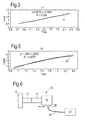
Figure 3 is a graph showing the selected data for R2 analysis in the method of determining the quality of a good inertia weld shown infigure 2 . -
Figure 4 is a graph showing a method of determining the quality of a non optimum inertia friction weld according to the present invention. -
Figure 5 is a graph showing the selected data for R2 analysis in the method of determining the quality of a bad inertia weld shown infigure 4 . -
Figure 6 is a diagram showing an apparatus for friction welding a first component to a second component and an apparatus for determining the quality of the friction weld according to the present invention. - An
apparatus 10, as shown infigure 6 , for friction welding afirst component 12 to asecond component 14 comprises afirst device 16 to rotate, or oscillate, thefirst component 12 and asecond device 18 to hold thesecond component 14 rigidly. Thesecond device 18 and thesecond component 14 are also arranged to be movable towards or away from thefirst component 12 such that thesecond component 14 is movable into contact with thefirst component 12 when thefirst component 12 is rotated, or oscillated, to generate heat by friction between thefirst component 12 and thesecond component 14 to produce a friction weld. Thus theapparatus 10 is arranged to produce a rotary friction weld or a linear friction weld between the first andsecond components - The
apparatus 10 also comprises asensor 20 to measure the loss of length of the first andsecond components sensor 20 is electrically connected to aprocessor 22 by a means ofdata transfer 24, e.g. a cable or a wireless transmitter and receiver etc, and theprocessor 22 is arranged to receive a signal from thesensor 20 indicating the loss of length of the first andsecond components - The
processor 22 is arranged to determine the quality of the friction weld between the first andsecond components processor 22 measures the loss of length of the first andsecond component figure 2 , during the friction welding process using the signal from thesensor 20. Then theprocessor 22 is arranged to determine the double differential with respect to time of the loss in length of the first andsecond components figure 2 . The differential with respect to time of the loss in length of the first andsecond components figure 2 . Theprocessor 22 is then arranged to determine the quality of the friction weld by fitting a predetermined polynomial function to the measured loss of length of the first andsecond components processor 22 determines the accuracy of fit of the predetermined polynomial function to the measured loss of length of the first andsecond components processor 22 determines the end of the defined time period T by identifying the start D of a final positive peak PF of the double differential with respect to time of the loss of length of the first andsecond components processor 22 compares the accuracy of the fit of the predetermined polynomial function to the measured loss of length of the first andsecond components second components processor 22 is a PC, a microprocessor or any other suitable device. -
Figures 2 and3 show an example of a friction weld in which the weld has an acceptable upset curve, or loss of length of the first and second components as a function of time, whereasfigures 4 and5 show an example of a friction weld in which the weld has an unacceptable upset curve, or loss of length of the first and second components as a function of time. It is seen infigure 4 that there are many positive and negative peaks in the double differential curve DD and the loss of length of the first andsecond components figure 2 there are fewer positive and negative peaks in the double differential curve D and the loss of length of the first andsecond components - The
processor 22 determines the quality of the inertia friction weld by calculating the R2 value of the linear fit to the loss in length of thecomponents components Figure 2 provides a high R2 fit, seefigure 3 , whereasfigure 4 provides a lower R2 fit, seefigure 5 . - The
processor 22 uses the above method where the loss of length of thecomponents - Alternatively the
processor 22 determines the quality of the inertia friction weld by calculating the R2 value of the non-linear fit to the loss in length of thecomponents components - The
processor 22 uses this method where the loss of length of thecomponents - The method of least squares, also known as regression analysis, is used to compare the data of the loss of the length of the components as a function of time from the sensor with a straight line in linear least squares or a curve in non-linear least squares. The best fit of the data of the loss of the length of the components as a function of time to the straight line or curve is when the sum of the squares of the residuals, R2, has its least value and a residual is the difference between a data point of the loss of the length of the components as a function of time and the straight line or curve used for the least squares method.
- In the non-linear least squares method the curve may be a straight line, a parabola or any other polynomial type function.
- Although the present invention has been described with reference to the use of the least squares method it is equally possible to use any other suitable method of regression analysis, for example the Lasso method.
- The friction welding process may be linear friction welding, rotary friction welding, orbital friction welding or friction stir welding. The rotary frictional welding may be inertia friction welding, direct drive friction welding (also known as continuous drive friction welding) or hybrid rotary friction welding. Hybrid rotary friction welding is a hybrid of inertia friction welding and direct drive friction welding.
- The linear friction welding process may comprise welding a blade to a rotor. The linear friction welding process may comprise welding a fan blade to a fan rotor, a compressor blade to a compressor rotor or a turbine blade to a turbine rotor to make integrally bladed rotors, e.g. blisks or bladed disks, blings or bladed rings or blums or bladed drums, for gas turbine engines. The linear friction welding process may comprise welding a disc post to a disc. The linear friction welding process may comprise welding a fan disc post to a fan disc, a compressor disc post to a compressor disc or a turbine disc post to a turbine disc of gas turbine engines.
- The rotary welding process may comprise welding a first disc to a second disc, a shaft to a disc or a first shaft to a second shaft.
- The friction welding process may comprise welding titanium alloy components, nickel superalloy components, steel components or any other suitable combinations of alloys or metals.
- The method may be used to determine the quality of the weld in real-time monitoring of the friction welding process and adjusting the friction welding process.
- The value of R2 calculated by the present invention may be related to the integrity/quality of the weld whereas previously no quantitative solution existed. The present invention provides a method of quantifying weld quality which may be automated allowing the determination of the acceptability of the friction weld without interpretation by a skilled operator.
- Previously friction weld quality required manual and/or interpretation by a skilled operator. The present invention allows real-time monitoring of R2 for upset control during the friction welding process in combination with pressure or speed modulation to accelerate or decelerate the loss of in length accordingly by using the real-time double differential calculation of the loss in length curve to dynamically control the upset such that the double differential is within predefined limits.
- The start of the real time monitoring and the dynamic control of the upset may use one of four different possibilities depending upon the type of friction welding. The start of the dynamic control may be after a predetermined time, at a predetermined rotational speed, at a predetermined position (or upset or loss of length) or after a predetermined time for which the double differential with respect to time of the loss of length of the first and second components falls within predetermined upper and lower limits.
- In the real time monitoring and dynamic control of the upset the double differential with respect to time of the loss of length of the components is monitored to ensure it is within predefined limits for that particular friction weld. If the value for the double differential with respect to time of the loss of length of the components goes outside the predefined limits for that particular friction weld the parameters, e.g. pressure and/or speed, of the friction weld are adjusted to bring the double differential with respect to time of the loss of length of the components back within the predefined limits for that particular friction weld. If the double differential with respect to time of the loss of length of the components falls below a predefined lower limit for that particular friction weld then the pressure and/or speed are increased to bring the double differential with respect to time of the loss of length of the components back within the predefined limits for that particular friction weld. If the double differential with respect to time of the loss of length of the components rises above a predefined upper limit for that particular friction weld then the pressure and/or speed are decreased to bring the double differential with respect to time of the loss of length of the components back within the predefined limits for that particular friction weld. The speed may be rotational speed for rotary friction welding or oscillation speed for linear friction welding. The predefined limits for that particular weld are within the acceptable limits for that particular weld such that excursions of the value of the double differential with respect to time of the loss of length of the components outside the predefined limits does not deleteriously affect the friction weld. Note in
figure 2 the double differential curve C has a constant value of zero, or substantially zero, over the time period T for a linear acceptable upset rate. For a non-linear acceptable upset rate the double differential curve has constant value different to zero. The upper and lower predefined limits referred to are above and below these constant values. - The end of the real time monitoring and the dynamic control of the upset for inertia friction welding may use one of three different possibilities. Firstly, the end of the dynamic control may be after the speed of rotation reaches zero rpm or is within a predetermined range of zero rpm or the rotational speed reaches a predetermined value. Secondly, the end of the dynamic control may be after the time of the weld duration reaches a predetermined value. Thirdly, the end of the dynamic control may be after the upset or machine position has reached a predetermined value. Dynamic pressure control maintains the pressure that was applied when the predetermined value of the rotational speed is reached.
Claims (17)
- A method of determining the quality of a friction weld between two components (12,14), the method comprising joining two components (12,14) together using a friction welding process, measuring the loss of length of the components (12,14) as a function of time (A) during the friction welding process, determining the quality of the friction weld by fitting a curve to the measured loss of length of the components (12,14) as a function of time (A) over a defined time period (T), determining the accuracy of fit of the curve to the measured loss of length of the components (12,14) as a function of time (A), comparing the accuracy of the fit of the curve to the measured loss of length of the components (12,14) as a function of time (A) with acceptable values of accuracy to determine if the quality of the friction weld is acceptable.
- A method as claimed in claim 1 comprising determining the quality of the friction weld by calculating the R2 value of the linear fit to the loss in length of the components (12,14) as a function of time (A) over the defined time period (T), calculating R2 from the least square difference of the linear fit over the defined time period (T) of the loss of length of the components (12,14) as a function of time (A) and comparing the calculated value of R2 with acceptable values of R2 to determine if the quality of the friction weld is acceptable.
- A method as claimed in claim 1 comprising determining the quality of the friction weld by calculating the R2 value of the non-linear fit to the loss in length of the components (12,14) as a function of time (A) over the defined time period (T), calculating R2 from the least square difference of the non-linear fit over the defined time period (T) of the loss of length of the components (12,14) as a function of time (A) and comparing the calculated value of R2 with acceptable values of R2 to determine if the quality of the friction weld is acceptable.
- A method as claimed in any of claims 1 to 3 wherein the friction welding process is linear friction welding, rotary friction welding, orbital friction welding or friction stir welding.
- A method as claimed in claim 4 wherein the rotary friction welding is inertia friction welding, direct drive rotary friction welding or hybrid rotary friction welding.
- A method as claimed in claim 4 wherein the linear friction welding process comprises welding a blade to a rotor.
- A method as claimed in claim 6 wherein the linear friction welding process comprises welding a fan blade to a fan rotor, a compressor blade to a compressor rotor or a turbine blade to a turbine rotor.
- A method as claimed in claim 4 or claim 5 wherein the rotary friction welding process comprises welding a first shaft to a second shaft, a first disc to a second disc or a shaft to a disc.
- A method as claimed in any of claims 1 to 8 wherein the friction welding process comprises welding titanium alloy components, nickel superalloy components, steel components or any other suitable combination of alloys or metals.
- A method as claimed in any of claims 1 to 9 comprising determining the double differential with respect to time of the loss in length of the components (12,14) as a function of time (C).
- A method as claimed in claim 10 comprising determining the end of the defined time period (T) by identifying the start of the final positive peak of the double differential with respect to time of the loss of length of the components (12,14) as a function of time (C).
- A method as claimed in claim 10 comprising monitoring the double differential with respect to time of the loss in length of the components (12,14) as a function of time (C) to ensure it is within predefined limits for the friction weld.
- A method as claimed in claim 12 comprising determining that the double differential with respect to time of the loss of length of the components (12,14) falls below a predefined lower limit for the friction weld and increasing the pressure and/or speed to bring the double differential with respect to time of the loss of length of the components (12,14) back within the predefined limits for the friction weld.
- A method as claimed in claim 12 or claim 13 comprising determining that the double differential with respect to time of the loss of length of the components (12,14) rises above a predefined upper limit for the friction weld and decreasing the pressure and/or speed to bring the double differential with respect to time of the loss of length of the components (12,14) back within the predefined limits for the friction weld.
- An apparatus for determining the quality of a friction weld between two components, comprising an apparatus (10) for friction welding two components (12,14) together, a sensor (20) to measure the loss of length of the components (12,14) as a function of time (A) during the friction welding process, characterised by a device (22) to determine the quality of the friction weld by fitting a curve to the measured loss of length of the components (12,14) as a function of time (A) over a defined time period (T), a device (22) to determine the accuracy of fit of the curve to the measured loss of length of the components (12,14) as a function of time (A), a device (22) to compare the accuracy of the fit of the curve to the measured loss of length of the components (12,14) as a function of time (A) with acceptable values of accuracy to determine if the quality of the friction weld is acceptable.
- An apparatus as claimed in claim 15 wherein the apparatus (10) for friction welding two components (12,14) together comprises a first device (16) to rotate the first component (12) and a second device (18) to hold the second component (14) rigidly.
- An apparatus as claimed in claim 15 wherein the apparatus (10) for friction welding two components (12,14) together comprises a first device (16) to oscillate the first component (12) and a second device (18) to hold the second component (14) rigidly.
Applications Claiming Priority (1)
| Application Number | Priority Date | Filing Date | Title |
|---|---|---|---|
| GBGB1002717.5A GB201002717D0 (en) | 2010-02-18 | 2010-02-18 | An apparatus and a method of determining the quality of a friction weld |
Publications (1)
| Publication Number | Publication Date |
|---|---|
| EP2361715A1 true EP2361715A1 (en) | 2011-08-31 |
Family
ID=42113972
Family Applications (1)
| Application Number | Title | Priority Date | Filing Date |
|---|---|---|---|
| EP11153317A Withdrawn EP2361715A1 (en) | 2010-02-18 | 2011-02-04 | An apparatus and a method of determining the quality of a friction weld |
Country Status (3)
| Country | Link |
|---|---|
| US (1) | US8342382B2 (en) |
| EP (1) | EP2361715A1 (en) |
| GB (1) | GB201002717D0 (en) |
Families Citing this family (6)
| Publication number | Priority date | Publication date | Assignee | Title |
|---|---|---|---|---|
| US10239153B2 (en) * | 2012-09-06 | 2019-03-26 | Edison Welding Institute, Inc. | Inertia friction welding system for martensite-free joining of materials |
| US8651361B1 (en) * | 2013-02-13 | 2014-02-18 | The Boeing Company | Method for angular oscillation friction welding to an axially symmetric weld surface |
| US9314878B2 (en) * | 2013-09-12 | 2016-04-19 | Ford Global Technologies, Llc | Non-destructive aluminum weld quality estimator |
| US10451085B2 (en) * | 2016-10-05 | 2019-10-22 | Borgwarner Inc. | Assembly methods for the connection of a turbine wheel to a shaft |
| CN109014558B (en) * | 2017-06-12 | 2020-08-04 | 中国航空制造技术研究院 | A method to improve the precision of linear friction welding shortening |
| WO2020017514A1 (en) * | 2018-07-18 | 2020-01-23 | シチズン時計株式会社 | Machine tool |
Citations (4)
| Publication number | Priority date | Publication date | Assignee | Title |
|---|---|---|---|---|
| GB1439277A (en) * | 1972-09-05 | 1976-06-16 | Production Technology Inc | Inertial friction welding |
| US4757932A (en) * | 1983-04-07 | 1988-07-19 | Rolls-Royce Plc | Control of friction and inertia welding processes |
| DE19917896A1 (en) * | 1998-04-20 | 1999-10-28 | Nissan Motor | Controlling spot welding process |
| US20060043155A1 (en) * | 2004-08-24 | 2006-03-02 | Jeff Lovin | Method and system of friction welding |
Family Cites Families (17)
| Publication number | Priority date | Publication date | Assignee | Title |
|---|---|---|---|---|
| GB1293141A (en) * | 1969-07-16 | 1972-10-18 | Welding Inst | Improvements relating to friction welding |
| US4067490A (en) | 1974-10-10 | 1978-01-10 | Caterpillar Tractor Co. | Quality control method for inertial welding |
| US3998373A (en) * | 1975-09-15 | 1976-12-21 | Production Technology Inc. | Length compensator for friction welding machines |
| GB2137774B (en) | 1983-04-07 | 1986-09-24 | Rolls Royce | Automatic control of friction and inertia welding process |
| JP3209170B2 (en) * | 1997-12-02 | 2001-09-17 | 日本軽金属株式会社 | Friction welding method and joint for aluminum alloy hollow member |
| US6808931B1 (en) * | 1998-02-27 | 2004-10-26 | The United States Of America As Represented By The Secretary Of Health And Human Services | Method for the determination of hexavalent chromium using ultrasonication and strong anion exchange solid phase extraction |
| US6727691B2 (en) * | 2000-06-26 | 2004-04-27 | Jentek Sensors, Inc. | High resolution inductive sensor arrays for material and defect characterization of welds |
| US6670574B1 (en) * | 2002-07-31 | 2003-12-30 | Unitek Miyachi Corporation | Laser weld monitor |
| US6909459B2 (en) * | 2002-08-21 | 2005-06-21 | Alpha Innotech Corporation | Method of and apparatus for extending signal ranges of digital images |
| US7216793B2 (en) | 2003-08-22 | 2007-05-15 | Edison Welding Institute, Inc. | Friction stir welding travel axis load control method and apparatus |
| DE102004030381B3 (en) | 2004-06-23 | 2006-01-12 | Eads Deutschland Gmbh | Online quality testing method for use during friction stir welding comprises feeding a friction tool under rotation and pressure into the material of the workpieces being welded and guiding along a joining site of the workpieces |
| GB0418524D0 (en) * | 2004-08-19 | 2004-09-22 | Rolls Royce Plc | Process and apparatus for inertia friction welding |
| US7080770B2 (en) * | 2004-09-03 | 2006-07-25 | Manufacturing Technology, Inc. | Method and system of inertia friction welding |
| US7617313B1 (en) * | 2004-12-27 | 2009-11-10 | Sprint Communications Company L.P. | Metric transport and database load |
| DE102005032170A1 (en) | 2005-07-09 | 2007-01-11 | Technische Universität Ilmenau | Friction friction welding tool and method and arrangement for online control of a friction stir welding process |
| KR20100012056A (en) * | 2007-06-22 | 2010-02-04 | 리스판스 지네틱스, 인크. | Methods for isolating long fragment rna from fixed samples |
| US20090255980A1 (en) | 2008-04-15 | 2009-10-15 | Lockheed Martin Corporation | Control systems for friction stir welding of titanium alloys and other high temperature materials |
-
2010
- 2010-02-18 GB GBGB1002717.5A patent/GB201002717D0/en not_active Ceased
-
2011
- 2011-02-04 EP EP11153317A patent/EP2361715A1/en not_active Withdrawn
- 2011-02-04 US US13/021,245 patent/US8342382B2/en not_active Expired - Fee Related
Patent Citations (4)
| Publication number | Priority date | Publication date | Assignee | Title |
|---|---|---|---|---|
| GB1439277A (en) * | 1972-09-05 | 1976-06-16 | Production Technology Inc | Inertial friction welding |
| US4757932A (en) * | 1983-04-07 | 1988-07-19 | Rolls-Royce Plc | Control of friction and inertia welding processes |
| DE19917896A1 (en) * | 1998-04-20 | 1999-10-28 | Nissan Motor | Controlling spot welding process |
| US20060043155A1 (en) * | 2004-08-24 | 2006-03-02 | Jeff Lovin | Method and system of friction welding |
Also Published As
| Publication number | Publication date |
|---|---|
| GB201002717D0 (en) | 2010-04-07 |
| US20120012644A1 (en) | 2012-01-19 |
| US8342382B2 (en) | 2013-01-01 |
Similar Documents
| Publication | Publication Date | Title |
|---|---|---|
| US8342382B2 (en) | Determining the quality of a friction weld using a double differential | |
| Fehrenbacher et al. | Effects of tool–workpiece interface temperature on weld quality and quality improvements through temperature control in friction stir welding | |
| Chamanfar et al. | A review on inertia and linear friction welding of Ni-based superalloys | |
| US8777089B2 (en) | Process control method | |
| Chamanfar et al. | Mechanical property and microstructure of linear friction welded WASPALOY | |
| EP3213856B1 (en) | Process for conditioning of a shear zone for friction welding | |
| Fehrenbacher et al. | Measurement of tool-workpiece interface temperature distribution in friction stir welding | |
| Grant et al. | Finite element process modelling of inertia friction welding advanced nickel-based superalloy | |
| JP6121520B2 (en) | Acting force adjustment for process control of friction stir work | |
| KR20040048426A (en) | Method For Friction Stir Welding | |
| EP0995534B1 (en) | Superspeed inertia welding | |
| Chamanfar et al. | Modeling grain size and strain rate in linear friction welded waspaloy | |
| CN107971625A (en) | It is a kind of to adjust inertia friction welder main shaft side and the special method of tailstock side concentricity | |
| CN105855691A (en) | Multifunctional friction stir welding tool | |
| BR102016019996A2 (en) | welding methods and determination of welding control parameters | |
| Attallah et al. | Inertia friction welding (IFW) for aerospace applications | |
| EP1634671A2 (en) | Process and apparatus for friction welding | |
| EP2012032A2 (en) | Magnetic bearing unit | |
| Hattingh et al. | Analysis of the FSW force footprint and its relationship with process parameters to optimise weld performance and tool design | |
| JPH09303532A (en) | Wet clutch break-in method and apparatus | |
| Gibson et al. | Evaluating the potential for remote in-process monitoring of tool wear in friction stir welding of stainless steel | |
| JP7190092B2 (en) | Defect detection method and defect detection device | |
| CN205798684U (en) | A kind of multifunctional stirring friction soldering set | |
| Artem’ev et al. | Test procedure of cladded alloys for resistance against high temperature abrasive wear | |
| Fehrenbacher et al. | Towards process control of friction stir welding for different aluminum alloys |
Legal Events
| Date | Code | Title | Description |
|---|---|---|---|
| PUAI | Public reference made under article 153(3) epc to a published international application that has entered the european phase |
Free format text: ORIGINAL CODE: 0009012 |
|
| AK | Designated contracting states |
Kind code of ref document: A1 Designated state(s): AL AT BE BG CH CY CZ DE DK EE ES FI FR GB GR HR HU IE IS IT LI LT LU LV MC MK MT NL NO PL PT RO RS SE SI SK SM TR |
|
| AX | Request for extension of the european patent |
Extension state: BA ME |
|
| STAA | Information on the status of an ep patent application or granted ep patent |
Free format text: STATUS: THE APPLICATION IS DEEMED TO BE WITHDRAWN |
|
| 18D | Application deemed to be withdrawn |
Effective date: 20120301 |