EP2361595A2 - Height adjustable bed with a push chain assembly - Google Patents
Height adjustable bed with a push chain assembly Download PDFInfo
- Publication number
- EP2361595A2 EP2361595A2 EP11153194A EP11153194A EP2361595A2 EP 2361595 A2 EP2361595 A2 EP 2361595A2 EP 11153194 A EP11153194 A EP 11153194A EP 11153194 A EP11153194 A EP 11153194A EP 2361595 A2 EP2361595 A2 EP 2361595A2
- Authority
- EP
- European Patent Office
- Prior art keywords
- chain
- bed
- frame
- lead screw
- lift assembly
- Prior art date
- Legal status (The legal status is an assumption and is not a legal conclusion. Google has not performed a legal analysis and makes no representation as to the accuracy of the status listed.)
- Withdrawn
Links
Images





Classifications
-
- A—HUMAN NECESSITIES
- A61—MEDICAL OR VETERINARY SCIENCE; HYGIENE
- A61G—TRANSPORT, PERSONAL CONVEYANCES, OR ACCOMMODATION SPECIALLY ADAPTED FOR PATIENTS OR DISABLED PERSONS; OPERATING TABLES OR CHAIRS; CHAIRS FOR DENTISTRY; FUNERAL DEVICES
- A61G7/00—Beds specially adapted for nursing; Devices for lifting patients or disabled persons
- A61G7/002—Beds specially adapted for nursing; Devices for lifting patients or disabled persons having adjustable mattress frame
- A61G7/012—Beds specially adapted for nursing; Devices for lifting patients or disabled persons having adjustable mattress frame raising or lowering of the whole mattress frame
-
- A—HUMAN NECESSITIES
- A61—MEDICAL OR VETERINARY SCIENCE; HYGIENE
- A61G—TRANSPORT, PERSONAL CONVEYANCES, OR ACCOMMODATION SPECIALLY ADAPTED FOR PATIENTS OR DISABLED PERSONS; OPERATING TABLES OR CHAIRS; CHAIRS FOR DENTISTRY; FUNERAL DEVICES
- A61G7/00—Beds specially adapted for nursing; Devices for lifting patients or disabled persons
- A61G7/002—Beds specially adapted for nursing; Devices for lifting patients or disabled persons having adjustable mattress frame
- A61G7/005—Beds specially adapted for nursing; Devices for lifting patients or disabled persons having adjustable mattress frame tiltable around transverse horizontal axis, e.g. for Trendelenburg position
-
- A—HUMAN NECESSITIES
- A61—MEDICAL OR VETERINARY SCIENCE; HYGIENE
- A61G—TRANSPORT, PERSONAL CONVEYANCES, OR ACCOMMODATION SPECIALLY ADAPTED FOR PATIENTS OR DISABLED PERSONS; OPERATING TABLES OR CHAIRS; CHAIRS FOR DENTISTRY; FUNERAL DEVICES
- A61G7/00—Beds specially adapted for nursing; Devices for lifting patients or disabled persons
- A61G7/002—Beds specially adapted for nursing; Devices for lifting patients or disabled persons having adjustable mattress frame
- A61G7/015—Beds specially adapted for nursing; Devices for lifting patients or disabled persons having adjustable mattress frame divided into different adjustable sections, e.g. for Gatch position
-
- A—HUMAN NECESSITIES
- A61—MEDICAL OR VETERINARY SCIENCE; HYGIENE
- A61G—TRANSPORT, PERSONAL CONVEYANCES, OR ACCOMMODATION SPECIALLY ADAPTED FOR PATIENTS OR DISABLED PERSONS; OPERATING TABLES OR CHAIRS; CHAIRS FOR DENTISTRY; FUNERAL DEVICES
- A61G7/00—Beds specially adapted for nursing; Devices for lifting patients or disabled persons
- A61G7/002—Beds specially adapted for nursing; Devices for lifting patients or disabled persons having adjustable mattress frame
- A61G7/018—Control or drive mechanisms
Definitions
- the subject matter described herein relates to height adjustable beds and particularly to a bed whose height adjustment system employs a push chain assembly.
- Beds used in health care facilities and home care settings include a base frame, an elevatable frame and a lift system allowing a patient or caregiver to adjust the height of the elevatable frame.
- the lift system components reside beneath the elevatable frame and therefore should be compact so that the frame can be positioned at very low elevations. Compactness also makes space available for other under-bed components.
- the lift system must also have enough vertical reach to allow the user to raise the frame high enough for a caregiver to attend to the bed occupant.
- Lift systems that employ telescoping components can satisfy the vertical positioning requirements. However the telescoping components can be susceptible to binding. Therefore, despite the merits of telescoping systems, it is desirable to enlarge the universe of design choices by developing non-telescoping alternatives.
- a bed comprising a base frame having a head end and a foot end, an elevatable fame also having a head end and a foot end, a lift assembly comprising an actuation system connected to one of the frames, a push chain having an actuator end driven by a lead screw and a distal end connected to the other of the frames.
- Rotary motion of the lead screw changes elevation of the elevating frame relative to the base frame.
- a framework 12 for a hospital bed has a base frame 14 and an elevatable frame 16 whose elevation E relative to the base frame is adjustable.
- the framework extends longitudinally from a head end 18 to a foot end 20 and laterally from a left side 22 to a right side 24.
- the elevatable frame supports upper body, thigh, and calf deck section frames 30, 32, 34.
- the angular orientation of the deck section frames is adjustable.
- Deck frame 30 is shown at a horizontal orientation
- deck frame 32 is shown at an orientation ⁇
- frame 34 is shown at an orientation ⁇ .
- Deck sections, not shown are affixed to each deck frame.
- a mattress, also not shown, rests atop the deck sections.
- Major and minor load bearing links 40, 42 at each of the four corners of the bed bear part of the weight of the elevatable frame and any other loads applied thereto.
- the links also stabilize the elevatable frame.
- the illustrations also include longitudinal, lateral and vertical reference axes.
- the foot end of the elevating frame includes a cross member 46 and a bracket 48 with ears 50.
- the bracket is attached to the cross member, e.g. by welding.
- a rod 52 extends between the ears.
- the head end of the elevating frame includes a cross member 56 and a set of brackets 58 attached to the cross member.
- Each bracket has a web 60 with an elongated slot 62 therein and a pair of flanges 64.
- the web and flanges define a channel 68.
- a slider block 70 resides between the flanges of each bracket and is translatable along the channel.
- a rod 72 extends laterally through the slider blocks. The lateral extremities of the rod are pivotably connected to the left and right major links 40 at the head end.
- the bed includes a head end lift assembly 76 and a foot end lift assembly 78 most easily visible in FIGS. 2 , 3 (both assemblies) and 7 (head assembly only).
- the assemblies are substantially similar to each other and it will suffice to describe only the head end lift assembly.
- the head end assembly includes an actuation system comprising an actuator 82 connected to the base frame by a bracket 84, and a lead screw 86 projecting from the actuator and rotationally driven thereby.
- the actuation system also includes a translatable nut 88 having a head end 90 and a shank 92. The nut is mounted on the threads of the lead screw.
- the actuation system also includes an internally threaded sleeve 94 installed on the shank end of the nut, and a nut adaptor 98 sandwiched between the sleeve and the head of the nut.
- the nut adaptor circumscribes the lead screw and includes a triplet of vertically extending projections 100 defining a pair of slots 104.
- the lead screw has a rotational axis 102 substantially nonparallel to the direction of elevation E. In the illustrated embodiment the lead screw axis is substantially horizontal.
- the lift assembly also includes a push chain 106.
- a typical push chain comprises a series of links. Each link is flexibly connected to its neighboring link at their cross axes. However the ends of the links are designed to interlock with the ends of the neighboring links such that when a thrust or compressive force is applied to the chain in the linkwise direction, the links lock together so that the chain resists bending in one direction but is able to bend or coil in the other direction. Under tension, the chain acts as ordinary chain.
- the illustrated push chain includes a left link plates 108, a right link plates 110, interlink rollers 112, left outboard rollers 114, right outboard rollers 116 and various spacers 118. Connector pins 120 connect the link plates, rollers and spacers together.
- each link plate includes a shoulder 122 ( FIG. 9 ) that effects the aforementioned interlocking.
- the chain extends in a linkwise direction from an actuator end 124 (i.e. the end closest to the actuator) to a distal end 126.
- the terminal link plates at the distal end of the foot end chain are connected to rod 52, for example by welding.
- the terminal link at the distal end of the head end chain is connected to rod 72, for example by welding.
- the terminal link at the actuator ends of both chains rest in slots 104 in the respective nut adaptor and are welded to the nut adaptor.
- the distal ends of the lift chains are laterally offset from each other as seen in FIGS. 1-3 .
- a chain guide 130 is connected to the base frame.
- the chain guide includes left and right rails 132, 134 each of which includes a laterally inwardly facing groove 136, 138.
- the guide has an actuator end 140 near actuator 82 and a remote end 142 near the longitudinal extremity of the frame.
- the illustrated chain guide has a horizontal portion 144 and a short vertical portion 146.
- a corner portion 148 joins the longitudinal and vertical portions of the guide to each other.
- the grooves in the corner portion of the guide rails are curved to connect the grooves of the horizontal portions of each rail with those of the vertical portions of each rail.
- the outboard rollers 114, 116 of the lift chain project laterally into the rail grooves 136, 138 so that the rails flank at least a portion of the chain.
- Limit switches 154 are secured to the chain guide, one near its actuator end and one near its remote end.
- the linkwise direction of the chain is partly substantially parallel to the lead screw rotational axis 102 and partly substantially nonparallel to the lead screw rotational axis.
- the nonparallel part is substantially perpendicular to the lead screw axis 102.
- the chain guide flanks at least the portion of the chain (e.g. corner 148) that joins the substantially parallel part thereof to the substantially nonparallel part thereof.
- each actuator output shaft rotates its lead screw in a "forward" rotational sense so that the nuts 88 advance along the screws thereby translating the nut adaptors 98 toward the ends of the bed.
- Translation of the nut adaptors pushes the chains along the chain guides.
- the corner portions of the chain guides turn the chain links from an orientation parallel to the rotational axis to an orientation perpendicular to the axis.
- As the chains advance their distal ends push vertically on rods 52, 72 to increase the elevation of the elevating frame.
- Each actuator stops when its associated nut adaptor 98 contacts the limit switch near the remote end 142 of the chain guide. Alternatively the travel limits could be integrated into the actuator by way of an electrical feedback.
- each actuator output shaft rotates its lead screw in a "reverse" rotational sense.
- the nuts 88 retreat along the lead screws thereby translating the nut adaptors 98 away from the ends of the bed.
- Translation of the nut adaptors pulls the chain through the chain guide.
- the corner portion of the chain guide turns the chain links from an orientation perpendicular to the rotational axis to an orientation parallel to the axis. Retraction of the chain allows the elevatable frame to move to a lower elevation while still being vertically supported by the chain.
- Each actuator stops when its associated nut adaptor 98 contacts the limit switch 154 near the actuator end 140 of the chain guide. Alternatively the travel limits could be integrated into the actuator by way of an electrical feedback.
- the actuators can be rotated differentially (i.e. in opposite directions, in the same direction at different speeds, or with one actuator operating and one not operating) to differentially adjust the elevation of the head and foot ends of frame 16.
- the slider blocks 70 at the head end of the bed slide along the channel 68.
- Differential operation of the actuators changes the orientation of the elevatable frame.
- FIG. 9 is a schematic representation of the above described embodiment. Rotation of the lead screw 86 causes the nut 88 to advance or retract, thereby pushing or pulling the chain.
- the chain moves through the chain guide, which changes the linkwise direction from vertical to horizontal or vice versa, thereby raising or lowering the elevatable frame.
- FIG. 10 is a schematic representation of a second embodiment in which the actuators are connected to the elevatable frame 16 rather than to the base frame 14. Operation of the actuator 82 advances the leadscrew vertically upwardly or downwardly through the nut to raise or lower the elevatable frame. The chain 106 remains stationary but continues to bear part of the weight of the elevatable frame.
Landscapes
- Health & Medical Sciences (AREA)
- Nursing (AREA)
- Life Sciences & Earth Sciences (AREA)
- Animal Behavior & Ethology (AREA)
- General Health & Medical Sciences (AREA)
- Public Health (AREA)
- Veterinary Medicine (AREA)
- Invalid Beds And Related Equipment (AREA)
Abstract
Description
- The subject matter described herein relates to height adjustable beds and particularly to a bed whose height adjustment system employs a push chain assembly.
- Beds used in health care facilities and home care settings include a base frame, an elevatable frame and a lift system allowing a patient or caregiver to adjust the height of the elevatable frame. The lift system components reside beneath the elevatable frame and therefore should be compact so that the frame can be positioned at very low elevations. Compactness also makes space available for other under-bed components. However the lift system must also have enough vertical reach to allow the user to raise the frame high enough for a caregiver to attend to the bed occupant. Lift systems that employ telescoping components can satisfy the vertical positioning requirements. However the telescoping components can be susceptible to binding. Therefore, despite the merits of telescoping systems, it is desirable to enlarge the universe of design choices by developing non-telescoping alternatives.
- The subject matter disclosed herein is a bed comprising a base frame having a head end and a foot end, an elevatable fame also having a head end and a foot end, a lift assembly comprising an actuation system connected to one of the frames, a push chain having an actuator end driven by a lead screw and a distal end connected to the other of the frames. Rotary motion of the lead screw changes elevation of the elevating frame relative to the base frame.
- The invention will now be further described by way of example with reference to the accompanying drawings, in which:
-
FIG. 1 is a perspective view of a framework for a hospital bed showing a base frame, an elevatable frame and a set of orientation adjustable deck frames as seen by an observer looking from above and positioned to the right of the framework. -
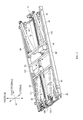
FIG. 2 is a view of the base frame ofFIG. 1 showing head and foot end lift assemblies for changing the elevation and/or orientation of the elevating frame relative to the base frame and also showing a set of load bearing links in a folded state consistent with the elevatable frame being at a low elevation. -
FIG. 3 is a view similar toFIG. 2 showing the links in an unfolded state consistent with the elevatable frame being at a higher elevation. -
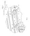
FIG. 4 is a perspective view of the foot end of the framework as seen by an observer looking from underneath and positioned to the right of the framework. -
FIG. 5 is a perspective view of the head end of the framework as seen by an observer looking from underneath and positioned slightly to the right of the longitudinal center. -
FIG. 6 is an enlarged view of a portion ofFIG. 5 viewed from a slightly different perspective. -
FIG. 7 is a partially exploded perspective view of the head end lift assembly as seen by an observer looking from underneath and positioned to the right of the framework. -
FIG. 8 is a more completely exploded, perspective view of the head end lift assembly as seen by an observer looking from above and positioned to the left of the framework. -
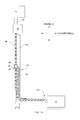
FIG. 9 is a schematic, side elevation view showing the arrangement of the lift assembly components ofFIGS. 1-8 . -
FIG. 10 is a schematic, side elevation view showing an alternate arrangement of the lift assembly components. - Referring to
FIGS. 1-3 , aframework 12 for a hospital bed has abase frame 14 and anelevatable frame 16 whose elevation E relative to the base frame is adjustable. The framework extends longitudinally from ahead end 18 to afoot end 20 and laterally from aleft side 22 to aright side 24. The elevatable frame supports upper body, thigh, and calfdeck section frames Deck frame 30 is shown at a horizontal orientation,deck frame 32 is shown at an orientation α andframe 34 is shown at an orientation β. Deck sections, not shown, are affixed to each deck frame. A mattress, also not shown, rests atop the deck sections. Major and minorload bearing links - Referring to
FIG. 4 , the foot end of the elevating frame includes across member 46 and abracket 48 withears 50. The bracket is attached to the cross member, e.g. by welding. Arod 52 extends between the ears. - Referring to
FIGS. 5-6 , the head end of the elevating frame includes across member 56 and a set ofbrackets 58 attached to the cross member. Each bracket has aweb 60 with anelongated slot 62 therein and a pair offlanges 64. The web and flanges define achannel 68. As seen best inFIG. 6 aslider block 70 resides between the flanges of each bracket and is translatable along the channel. Arod 72 extends laterally through the slider blocks. The lateral extremities of the rod are pivotably connected to the left and rightmajor links 40 at the head end. - The bed includes a head
end lift assembly 76 and a footend lift assembly 78 most easily visible inFIGS. 2 ,3 (both assemblies) and 7 (head assembly only). The assemblies are substantially similar to each other and it will suffice to describe only the head end lift assembly. The head end assembly includes an actuation system comprising anactuator 82 connected to the base frame by abracket 84, and alead screw 86 projecting from the actuator and rotationally driven thereby. The actuation system also includes atranslatable nut 88 having ahead end 90 and ashank 92. The nut is mounted on the threads of the lead screw. The actuation system also includes an internally threadedsleeve 94 installed on the shank end of the nut, and anut adaptor 98 sandwiched between the sleeve and the head of the nut. The nut adaptor circumscribes the lead screw and includes a triplet of vertically extendingprojections 100 defining a pair ofslots 104. The lead screw has arotational axis 102 substantially nonparallel to the direction of elevation E. In the illustrated embodiment the lead screw axis is substantially horizontal. - The lift assembly also includes a
push chain 106. A typical push chain comprises a series of links. Each link is flexibly connected to its neighboring link at their cross axes. However the ends of the links are designed to interlock with the ends of the neighboring links such that when a thrust or compressive force is applied to the chain in the linkwise direction, the links lock together so that the chain resists bending in one direction but is able to bend or coil in the other direction. Under tension, the chain acts as ordinary chain. The illustrated push chain includes aleft link plates 108, aright link plates 110,interlink rollers 112,left outboard rollers 114,right outboard rollers 116 andvarious spacers 118.Connector pins 120 connect the link plates, rollers and spacers together. One end of each link plate includes a shoulder 122 (FIG. 9 ) that effects the aforementioned interlocking. The chain extends in a linkwise direction from an actuator end 124 (i.e. the end closest to the actuator) to adistal end 126. The terminal link plates at the distal end of the foot end chain are connected torod 52, for example by welding. The terminal link at the distal end of the head end chain is connected torod 72, for example by welding. The terminal link at the actuator ends of both chains rest inslots 104 in the respective nut adaptor and are welded to the nut adaptor. The distal ends of the lift chains are laterally offset from each other as seen inFIGS. 1-3 . - A
chain guide 130 is connected to the base frame. The chain guide includes left andright rails groove FIGS. 2-3 the guide has anactuator end 140 nearactuator 82 and aremote end 142 near the longitudinal extremity of the frame. The illustrated chain guide has ahorizontal portion 144 and a shortvertical portion 146. A corner portion 148 (seen best inFIGS. 8 and9 ) joins the longitudinal and vertical portions of the guide to each other. The grooves in the corner portion of the guide rails are curved to connect the grooves of the horizontal portions of each rail with those of the vertical portions of each rail. Theoutboard rollers rail grooves Limit switches 154 are secured to the chain guide, one near its actuator end and one near its remote end. - When the chain is installed in the chain guide as described above, the linkwise direction of the chain is partly substantially parallel to the lead screw
rotational axis 102 and partly substantially nonparallel to the lead screw rotational axis. In the illustrated embodiment the nonparallel part is substantially perpendicular to thelead screw axis 102. The chain guide flanks at least the portion of the chain (e.g. corner 148) that joins the substantially parallel part thereof to the substantially nonparallel part thereof. - To raise the
elevatable frame 16 without changing its orientation the head and foot end actuators are operated in unison. Each actuator output shaft rotates its lead screw in a "forward" rotational sense so that the nuts 88 advance along the screws thereby translating thenut adaptors 98 toward the ends of the bed. Translation of the nut adaptors pushes the chains along the chain guides. The corner portions of the chain guides turn the chain links from an orientation parallel to the rotational axis to an orientation perpendicular to the axis. As the chains advance, their distal ends push vertically onrods nut adaptor 98 contacts the limit switch near theremote end 142 of the chain guide. Alternatively the travel limits could be integrated into the actuator by way of an electrical feedback. - To lower the elevatable frame without changing its orientation the head and foot end actuators are again operated in unison so that each actuator output shaft rotates its lead screw in a "reverse" rotational sense. The nuts 88 retreat along the lead screws thereby translating the
nut adaptors 98 away from the ends of the bed. Translation of the nut adaptors pulls the chain through the chain guide. The corner portion of the chain guide turns the chain links from an orientation perpendicular to the rotational axis to an orientation parallel to the axis. Retraction of the chain allows the elevatable frame to move to a lower elevation while still being vertically supported by the chain. Each actuator stops when its associatednut adaptor 98 contacts thelimit switch 154 near theactuator end 140 of the chain guide. Alternatively the travel limits could be integrated into the actuator by way of an electrical feedback. - The actuators can be rotated differentially (i.e. in opposite directions, in the same direction at different speeds, or with one actuator operating and one not operating) to differentially adjust the elevation of the head and foot ends of
frame 16. During such operation the slider blocks 70 at the head end of the bed slide along thechannel 68. Differential operation of the actuators changes the orientation of the elevatable frame. -
FIG. 9 is a schematic representation of the above described embodiment. Rotation of thelead screw 86 causes thenut 88 to advance or retract, thereby pushing or pulling the chain. The chain moves through the chain guide, which changes the linkwise direction from vertical to horizontal or vice versa, thereby raising or lowering the elevatable frame. -
FIG. 10 is a schematic representation of a second embodiment in which the actuators are connected to theelevatable frame 16 rather than to thebase frame 14. Operation of the actuator 82 advances the leadscrew vertically upwardly or downwardly through the nut to raise or lower the elevatable frame. Thechain 106 remains stationary but continues to bear part of the weight of the elevatable frame. - Although this disclosure refers to specific embodiments, it will be understood by those skilled in the art that various changes in form and detail may be made.
Claims (8)
- A bed comprising:a base frame having a head end and a foot end;an elevatable frame having a head end and a foot end;a lift assembly comprising an actuation system connected to one of the frames, the actuation system including a lead screw; anda push chain having an actuator end driven by the lead screw and a distal end connected to the other of the frames;wherein rotary motion of the lead screw changes elevation of the elevating frame relative to the base frame.
- The bed of claim 1 wherein the lead screw has a rotational axis substantially nonparallel to the direction of elevation.
- The bed of claim 2 including a chain guide flanking at least a portion of the chain.
- The bed of claim 3 wherein the chain has a linkwise direction, the linkwise direction being partly substantially parallel to the lead screw rotational axis and partly substantially nonparallel to the lead screw rotational axis, and wherein the chain guide flanks a portion of the chain that joins the substantially parallel part thereof to the substantially nonparallel part thereof.
- The bed of any preceding claim comprising a second lift assembly including a second actuation system connected to the other frame, and a second push chain having an actuator end connected to the second actuation system and a distal end connected to the other of the frames.
- The bed of claim 5 wherein the first lift assembly is a head end lift assembly, the second lift assembly is a foot end lift assembly, the first push chain is a head end push chain and the second push chain is a foot end push chain.
- The bed of claim 6 wherein the distal ends of the push chains are laterally offset from each other.
- The bed of any preceding claim including head end and foot end load bearing links extending from the base frame to the elevatable frame.
Applications Claiming Priority (1)
| Application Number | Priority Date | Filing Date | Title |
|---|---|---|---|
| US12/708,178 US8104120B2 (en) | 2010-02-18 | 2010-02-18 | Height adjustable bed with a push chain assembly |
Publications (2)
| Publication Number | Publication Date |
|---|---|
| EP2361595A2 true EP2361595A2 (en) | 2011-08-31 |
| EP2361595A3 EP2361595A3 (en) | 2012-04-11 |
Family
ID=44061428
Family Applications (1)
| Application Number | Title | Priority Date | Filing Date |
|---|---|---|---|
| EP11153194A Withdrawn EP2361595A3 (en) | 2010-02-18 | 2011-02-03 | Height adjustable bed with a push chain assembly |
Country Status (2)
| Country | Link |
|---|---|
| US (1) | US8104120B2 (en) |
| EP (1) | EP2361595A3 (en) |
Cited By (1)
| Publication number | Priority date | Publication date | Assignee | Title |
|---|---|---|---|---|
| WO2013052452A1 (en) | 2011-10-02 | 2013-04-11 | Invacare Corporation | Adjustable bed |
Families Citing this family (36)
| Publication number | Priority date | Publication date | Assignee | Title |
|---|---|---|---|---|
| GB2414177B8 (en) | 2003-03-11 | 2015-01-21 | Chg Hospital Beds Inc | Steerable ultra-low patient bed |
| US20150059094A1 (en) | 2005-02-22 | 2015-03-05 | Roger P. Jackson | Patient positioning support structure |
| US9295433B2 (en) | 2005-02-22 | 2016-03-29 | Roger P. Jackson | Synchronized patient elevation and positioning apparatus for use with patient positioning support systems |
| US7739762B2 (en) | 2007-10-22 | 2010-06-22 | Mizuho Orthopedic Systems, Inc. | Surgery table apparatus |
| US9744087B2 (en) | 2005-02-22 | 2017-08-29 | Roger P. Jackson | Patient support apparatus with body slide position digitally coordinated with hinge angle |
| US9468576B2 (en) | 2005-02-22 | 2016-10-18 | Roger P. Jackson | Patient support apparatus with body slide position digitally coordinated with hinge angle |
| US9186291B2 (en) | 2005-02-22 | 2015-11-17 | Roger P. Jackson | Patient positioning support structure with trunk translator |
| US7565708B2 (en) | 2005-02-22 | 2009-07-28 | Jackson Roger P | Patient positioning support structure |
| US10869798B2 (en) | 2006-05-05 | 2020-12-22 | Warsaw Orthopedic, Inc. | Patient positioning support apparatus with virtual pivot-shift pelvic pads, upper body stabilization and fail-safe table attachment mechanism |
| US9642760B2 (en) | 2006-05-05 | 2017-05-09 | Roger P. Jackson | Patient positioning support apparatus with virtual pivot-shift pelvic pads, upper body stabilization and fail-safe table attachment mechanism |
| US9737149B2 (en) * | 2010-09-10 | 2017-08-22 | Hill-Rom Services, Inc. | Height adjustable bed framework with a lift chain and a planetary gear train |
| US9119474B2 (en) * | 2011-09-24 | 2015-09-01 | Martin Husslage | Height adjustable multi-position bench and massage platform |
| WO2013058806A1 (en) | 2011-10-17 | 2013-04-25 | Jackson Roger P | Patient positioning support structure |
| US9561145B2 (en) | 2012-02-07 | 2017-02-07 | Roger P. Jackson | Fail-safe release mechanism for use with patient positioning support apparati |
| US8997274B2 (en) * | 2013-01-23 | 2015-04-07 | Edward Phillips | Adjustable furniture apparatus |
| US12011399B2 (en) | 2013-08-28 | 2024-06-18 | Warsaw Orthopedic, Inc. | Patient positioning support apparatus with fail-safe connector attachment mechanism |
| CA3129202C (en) | 2013-09-06 | 2023-12-19 | Stryker Corporation | Patient support usable with bariatric patients |
| US10188569B2 (en) | 2013-09-06 | 2019-01-29 | Stryker Corporation | Patient support usable with bariatric patients |
| US9402775B2 (en) | 2014-07-07 | 2016-08-02 | Roger P. Jackson | Single and dual column patient positioning and support structure |
| US9622928B2 (en) * | 2014-07-07 | 2017-04-18 | Roger P. Jackson | Radiolucent hinge for a surgical table |
| US10426679B2 (en) * | 2014-08-27 | 2019-10-01 | Umano Medical Inc. | Systems for patient support surface orientation and displacement |
| US10736803B2 (en) | 2016-02-26 | 2020-08-11 | Stryker Corporation | Lift assembly for patient support apparatus |
| CN107772902B (en) * | 2016-08-31 | 2018-11-20 | 麒盛科技股份有限公司 | A kind of beddo applied to the waist ejecting mechanism of beddo and including the waist ejecting mechanism |
| US10842701B2 (en) | 2016-10-14 | 2020-11-24 | Stryker Corporation | Patient support apparatus with stabilization |
| US10987268B2 (en) | 2017-04-21 | 2021-04-27 | Stryker Corporation | Emergency cot with a litter height adjustment mechanism |
| US10987260B2 (en) | 2017-04-21 | 2021-04-27 | Stryker Corporation | Patient handling apparatus with hydraulic control system |
| US12472112B2 (en) | 2017-04-21 | 2025-11-18 | Stryker Corporation | Patient handling apparatus with hydraulic control system |
| US11447334B2 (en) | 2019-05-03 | 2022-09-20 | Oshkosh Corporation | Electric grasping apparatus for refuse vehicle |
| US11505404B2 (en) | 2019-05-03 | 2022-11-22 | Oshkosh Corporation | Electric side loader arms for electric refuse vehicle |
| US11434681B2 (en) | 2019-05-03 | 2022-09-06 | Oshkosh Corporation | Electric tailgate for electric refuse vehicle |
| US11254500B2 (en) | 2019-05-03 | 2022-02-22 | Oshkosh Corporation | Refuse vehicle with electric reach apparatus |
| US11273978B2 (en) * | 2019-05-03 | 2022-03-15 | Oshkosh Corporation | Refuse vehicle with electric lift |
| US11896531B2 (en) | 2019-10-28 | 2024-02-13 | Stryker Corporation | Hydraulic circuit for a patient handling apparatus |
| US11583455B2 (en) | 2019-10-28 | 2023-02-21 | Stryker Corporation | Hydraulic valve and system |
| US11730650B2 (en) | 2019-12-30 | 2023-08-22 | Stryker Corporation | Patient support apparatus with hydraulic oscillation dampening |
| DE102020130186A1 (en) * | 2020-11-16 | 2022-05-19 | Paul Hettich Gmbh & Co. Kg | Household appliance with a storage container |
Family Cites Families (42)
| Publication number | Priority date | Publication date | Assignee | Title |
|---|---|---|---|---|
| US980181A (en) | 1909-08-19 | 1911-01-03 | Dorsey F Asbury | Chain rammer. |
| US2818189A (en) | 1954-12-07 | 1957-12-31 | Irvin F Schreck | Die handling unit for lift trucks |
| GB923442A (en) | 1959-02-27 | 1963-04-10 | Rolls Royce | Improvements in or relating to handling apparatus |
| US3021024A (en) | 1960-04-18 | 1962-02-13 | Nagin Tony | Fork lift truck pusher mechanism |
| US3153940A (en) | 1961-05-18 | 1964-10-27 | Ct D Etudes Et D Applic Des Te | Transmission device |
| US3672237A (en) | 1969-09-29 | 1972-06-27 | Tony Nagin | Load supporting chain and sprocket supporting structure therefor |
| US3845591A (en) * | 1973-06-11 | 1974-11-05 | J Stine | Expandable cover system |
| US4014136A (en) | 1974-07-18 | 1977-03-29 | Teleflex Morse Limited | Means for the opening and closing of angularly movable panels |
| US4299585A (en) | 1975-02-27 | 1981-11-10 | Nagin Jr Tony | Chain guide and mounting means |
| US4037744A (en) | 1976-05-10 | 1977-07-26 | Nagin Jr Tony | Lift truck pusher device |
| US4271830A (en) * | 1978-07-26 | 1981-06-09 | Moon Derryl E | Chiropractic table |
| JPS6053236B2 (en) | 1980-04-30 | 1985-11-25 | 敬之助 松谷 | Rollable stretchable structure |
| JPS60172429A (en) | 1984-02-17 | 1985-09-05 | Aioi Seiki Kk | Side-bent chain system hydraulic cylinder driving type push-pull operating device for tool and the like of working machine |
| US4644595A (en) | 1985-10-29 | 1987-02-24 | Daniel R A | Portable motorized bed lift apparatus |
| US5273392A (en) | 1986-01-02 | 1993-12-28 | Computer Aided Systems, Inc. | Automated work center and method |
| IT222350Z2 (en) | 1990-11-06 | 1995-02-17 | Ultraflex Srl | SERVOMECHANICAL CHAIN ACTUATOR FOR CLOSING AND OPENING WINDOWS |
| US5158568A (en) * | 1991-01-14 | 1992-10-27 | United Apothecary, Inc. | Lumbar spine therapy device |
| US5123916A (en) * | 1991-01-14 | 1992-06-23 | United Apothecary, Inc. | Lumbar spine therapy device |
| US5425442A (en) | 1993-01-13 | 1995-06-20 | Howard M. Lawn | Drive system for a vertical storage conveyor |
| US5490297A (en) * | 1994-09-01 | 1996-02-13 | Beta Medical Products, Inc. | Mobile imaging table |
| WO1996023433A1 (en) * | 1995-01-31 | 1996-08-08 | Krueger International, Inc. | Adjustable height table |
| DK135995A (en) | 1995-12-01 | 1997-06-02 | Rasmussen Kann Ind As | Operator with at least two display elements for opening and closing swivel windows |
| US5802639A (en) * | 1996-10-29 | 1998-09-08 | Midwest Air Technologies, Inc. | Variable force clutch for linear actuator |
| US6109424A (en) * | 1997-03-20 | 2000-08-29 | Fori Automation, Inc. | Chassis/body marriage lift machine |
| US6601677B1 (en) * | 1997-07-14 | 2003-08-05 | Vertical Mobility, L.L.C. | Convertible lift mechanism having a number of retractable stairs with a lift platform positioned thereunder |
| US5940911A (en) * | 1997-11-10 | 1999-08-24 | Wang; Yi-Lung | Multi-functional bed structure |
| EP0982018B1 (en) | 1998-08-24 | 2006-06-07 | Linet Spol. S.R.O. | Lifting device preferably for the height adjustment for patient beds or care beds |
| FR2786476B1 (en) | 1998-11-30 | 2001-02-23 | Serapid France | LOAD LIFT COLUMN |
| BR9916131A (en) * | 1998-12-11 | 2001-11-06 | Hill Rom Co Inc | Bed mounts, patient support for an articulated bed and articulated push handle for hospital beds, and hospital bed |
| US6659935B2 (en) * | 2000-09-21 | 2003-12-09 | Hill-Rom Services, Inc. | Lifting apparatus for patient support surface |
| US6890278B2 (en) | 2001-02-14 | 2005-05-10 | Jeffrey Theorin Prince | Chain with selectivity engaged links |
| US6684419B1 (en) * | 2002-01-08 | 2004-02-03 | Frank W. Perla | Bedside lower extremity lifting apparatus |
| AUPS074602A0 (en) * | 2002-02-25 | 2002-03-21 | Protean Global Pty Ltd | Lifting mechanism for use with health care equipment |
| JP2004129932A (en) * | 2002-10-11 | 2004-04-30 | Paramount Bed Co Ltd | Furniture lifting equipment |
| US20040177934A1 (en) | 2003-03-10 | 2004-09-16 | The Chamberlain Group, Inc. | Garage door movement apparatus |
| US7331425B2 (en) * | 2004-07-09 | 2008-02-19 | Gm Global Technology Operations, Inc. | Lift machine |
| US7621078B2 (en) | 2005-01-20 | 2009-11-24 | Drs Sustainment Systems, Inc. | Telescoping mast having variable height locking and a chain erection mechanism with a cable management system |
| US8707484B2 (en) * | 2005-02-22 | 2014-04-29 | Roger P. Jackson | Patient positioning support structure |
| DE102005054222A1 (en) | 2005-11-14 | 2007-05-16 | Maquet Gmbh & Co Kg | operating table |
| DE102007014648B4 (en) * | 2007-03-27 | 2017-07-13 | Siemens Healthcare Gmbh | Patient storage device for a magnetic resonance device |
| US7841030B2 (en) * | 2008-05-28 | 2010-11-30 | General Electric Company | Positioning systems and methods |
| US8074309B2 (en) * | 2009-03-04 | 2011-12-13 | Hill-Rom Services, Inc. | Height adjustable bed with a lift chain assembly and components thereof |
-
2010
- 2010-02-18 US US12/708,178 patent/US8104120B2/en active Active
-
2011
- 2011-02-03 EP EP11153194A patent/EP2361595A3/en not_active Withdrawn
Cited By (3)
| Publication number | Priority date | Publication date | Assignee | Title |
|---|---|---|---|---|
| WO2013052452A1 (en) | 2011-10-02 | 2013-04-11 | Invacare Corporation | Adjustable bed |
| EP2760312A4 (en) * | 2011-10-02 | 2015-06-24 | Invacare Corp | ADJUSTABLE BED |
| US9687400B2 (en) | 2011-10-02 | 2017-06-27 | Invacare Corp. | Adjustable bed |
Also Published As
| Publication number | Publication date |
|---|---|
| EP2361595A3 (en) | 2012-04-11 |
| US20110197361A1 (en) | 2011-08-18 |
| US8104120B2 (en) | 2012-01-31 |
Similar Documents
| Publication | Publication Date | Title |
|---|---|---|
| US8104120B2 (en) | Height adjustable bed with a push chain assembly | |
| US8640285B2 (en) | Hospital bed seat section articulation for chair egress | |
| US8621690B2 (en) | Hospital bed lift and braking mechanisms | |
| US10470954B2 (en) | Patient support apparatus with deck section link | |
| US20080148484A1 (en) | Frame for a patient-support apparatus | |
| US20120023673A1 (en) | Bed Frame Assembly with a Lift System having a Translatable Carriage | |
| MXPA02008926A (en) | Bed siderail. | |
| EP2772237A2 (en) | Adjustable bed | |
| AU2017201218A1 (en) | Lift assembly for patient support apparatus | |
| US10071005B2 (en) | Leg assembly for height adjustable patient support | |
| CN101563055B (en) | Hospital bed with adjustable head support | |
| US20190060145A1 (en) | Long term care bed | |
| US20120047652A1 (en) | Siderail mechanism | |
| EP2777672B1 (en) | Person support apparatus | |
| EP4057974B1 (en) | Lifting column | |
| US12544284B2 (en) | Bed lifting mechanism | |
| US12527408B2 (en) | Driving mechanism and adjustable bed therewith | |
| DE102006030939A1 (en) | Bed i.e. relocation bed, construction, has raising and lowering mechanism attached between support and bed frames to raise and lower lateral sides of bed frame, and locking system for fixing unlifted lateral sides | |
| US12532970B2 (en) | Extendable support frame for an articulating bed platform | |
| EP2873399B1 (en) | Person support apparatus | |
| DK3000454T3 (en) | BED, PROCEDURE FOR CONVERTING A BED TO A CHAIR, AND USING A BED | |
| CN118557384A (en) | Auxiliary lateral turning device | |
| JP2026063040A (en) | Bed equipment | |
| DE202006010380U1 (en) | Bed for long-term patient, comprises mechanism for temporary lifting one side individually for avoidance of bedsores | |
| DK2716270T3 (en) | Bed and use of a bed |
Legal Events
| Date | Code | Title | Description |
|---|---|---|---|
| PUAI | Public reference made under article 153(3) epc to a published international application that has entered the european phase |
Free format text: ORIGINAL CODE: 0009012 |
|
| AK | Designated contracting states |
Kind code of ref document: A2 Designated state(s): AL AT BE BG CH CY CZ DE DK EE ES FI FR GB GR HR HU IE IS IT LI LT LU LV MC MK MT NL NO PL PT RO RS SE SI SK SM TR |
|
| AX | Request for extension of the european patent |
Extension state: BA ME |
|
| PUAL | Search report despatched |
Free format text: ORIGINAL CODE: 0009013 |
|
| AK | Designated contracting states |
Kind code of ref document: A3 Designated state(s): AL AT BE BG CH CY CZ DE DK EE ES FI FR GB GR HR HU IE IS IT LI LT LU LV MC MK MT NL NO PL PT RO RS SE SI SK SM TR |
|
| AX | Request for extension of the european patent |
Extension state: BA ME |
|
| RIC1 | Information provided on ipc code assigned before grant |
Ipc: A61G 7/012 20060101AFI20120307BHEP |
|
| RIN1 | Information on inventor provided before grant (corrected) |
Inventor name: HEIDLAGE, JOHN K. Inventor name: HORNBACH, DAVID W. |
|
| 17P | Request for examination filed |
Effective date: 20121009 |
|
| RAP1 | Party data changed (applicant data changed or rights of an application transferred) |
Owner name: HILL-ROM SERVICES, INC. |
|
| 17Q | First examination report despatched |
Effective date: 20140306 |
|
| STAA | Information on the status of an ep patent application or granted ep patent |
Free format text: STATUS: THE APPLICATION IS DEEMED TO BE WITHDRAWN |
|
| 18D | Application deemed to be withdrawn |
Effective date: 20140717 |