EP2361552B1 - Anordnung zur Befestigung eines Sensors auf einer Objektvorderseite - Google Patents
Anordnung zur Befestigung eines Sensors auf einer Objektvorderseite Download PDFInfo
- Publication number
- EP2361552B1 EP2361552B1 EP10153965.8A EP10153965A EP2361552B1 EP 2361552 B1 EP2361552 B1 EP 2361552B1 EP 10153965 A EP10153965 A EP 10153965A EP 2361552 B1 EP2361552 B1 EP 2361552B1
- Authority
- EP
- European Patent Office
- Prior art keywords
- sensor
- ribbon
- subject
- sensor holder
- measuring assembly
- Prior art date
- Legal status (The legal status is an assumption and is not a legal conclusion. Google has not performed a legal analysis and makes no representation as to the accuracy of the status listed.)
- Active
Links
Images

Classifications
-
- A—HUMAN NECESSITIES
- A61—MEDICAL OR VETERINARY SCIENCE; HYGIENE
- A61B—DIAGNOSIS; SURGERY; IDENTIFICATION
- A61B5/00—Measuring for diagnostic purposes; Identification of persons
- A61B5/08—Detecting, measuring or recording devices for evaluating the respiratory organs
- A61B5/087—Measuring breath flow
- A61B5/0878—Measuring breath flow using temperature sensing means
-
- A—HUMAN NECESSITIES
- A61—MEDICAL OR VETERINARY SCIENCE; HYGIENE
- A61B—DIAGNOSIS; SURGERY; IDENTIFICATION
- A61B5/00—Measuring for diagnostic purposes; Identification of persons
- A61B5/08—Detecting, measuring or recording devices for evaluating the respiratory organs
- A61B5/097—Devices for facilitating collection of breath or for directing breath into or through measuring devices
-
- A—HUMAN NECESSITIES
- A61—MEDICAL OR VETERINARY SCIENCE; HYGIENE
- A61B—DIAGNOSIS; SURGERY; IDENTIFICATION
- A61B5/00—Measuring for diagnostic purposes; Identification of persons
- A61B5/48—Other medical applications
- A61B5/4806—Sleep evaluation
- A61B5/4818—Sleep apnoea
-
- A—HUMAN NECESSITIES
- A61—MEDICAL OR VETERINARY SCIENCE; HYGIENE
- A61B—DIAGNOSIS; SURGERY; IDENTIFICATION
- A61B5/00—Measuring for diagnostic purposes; Identification of persons
- A61B5/68—Arrangements of detecting, measuring or recording means, e.g. sensors, in relation to patient
- A61B5/6801—Arrangements of detecting, measuring or recording means, e.g. sensors, in relation to patient specially adapted to be attached to or worn on the body surface
- A61B5/6813—Specially adapted to be attached to a specific body part
- A61B5/6814—Head
- A61B5/6819—Nose
-
- A—HUMAN NECESSITIES
- A61—MEDICAL OR VETERINARY SCIENCE; HYGIENE
- A61B—DIAGNOSIS; SURGERY; IDENTIFICATION
- A61B5/00—Measuring for diagnostic purposes; Identification of persons
- A61B5/68—Arrangements of detecting, measuring or recording means, e.g. sensors, in relation to patient
- A61B5/6801—Arrangements of detecting, measuring or recording means, e.g. sensors, in relation to patient specially adapted to be attached to or worn on the body surface
- A61B5/6813—Specially adapted to be attached to a specific body part
- A61B5/6814—Head
- A61B5/682—Mouth, e.g., oral cavity; tongue; Lips; Teeth
Definitions
- This disclosure relates generally to an arrangement for fastening at least one sensor on a face of a subject to acquire one or more signals indicative of patient physiological parameter and also relates to a measuring assembly.
- sensors on a patient's face for measuring signals indicative of the patient's physiological condition.
- Sensors may acquire signals proportional to for example a body temperature, breathing gas concentration etc.
- One good example of a sensor placed is a respiration flow sensor used for measuring a breathing gas flow through a mouth and nose.
- Such sensors are used in hospital wards, home- or elderly care or in a sleep laboratory, where there is a need to detect a breathing deficiency or even apnea, caused by for example opiates, other medicine, an obstruction in the airways or as a consequence of a neurological disease or trauma.
- Existing respiration sensors are usually placed on the patient's face, on or near by the patient's mouth or on the upper lip, between the mouth and the nose.
- Some small and light sensors are commonly attached on the face with a tape or similarly gluing.
- Some sensors are attached on a face with a rubber band type string going around the patient's neck or occiput. It is obvious that if such sensors come off, as the glue looses its grip on the skin or if the rubber band snaps, there is a high risk that the sensor enters the patient's upper airways or trachea causing choking and death. Partly for that reason some sensors are attached with a helmet type rubber net dressed on the patient's whole head, but such configuration is uncomfortable to wear as the helmet type rubber net squeezes and presses the face and the head.
- Respiration sensors based on measuring pressure change caused by the flow of the breathing gas usually comprise voluminous pressure sensors and electronics due to they have been placed further away from patients face into a remote unit, such as a patient monitor or similar, and only the tubing used to sense and transfer the pressure change to the remote unit is placed on the patient's face.
- a remote unit such as a patient monitor or similar
- Such tubing is usually suspended under the nose, cannulas entering the nasal cavities, extending there on ears and continuing around the head to the remote unit or alternatively continuing from ears to the chest over the jaws.
- Tubes are commonly made of plastics and they are rather inflexible and uncomfortable to wear, furthermore the cannulas irritate the hawse pipes and are easily torn off by the patient.
- WO 2008/019294 discloses nasal and oral patient interfaces for sampling carbon dioxide and for delivering supplemental oxygen, but also for monitoring gas and physiological function, and for other monitoring modalities.
- a measuring assembly according to the invention is defined in independent claim 1.
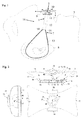
- Figure 1 shows an arrangement 1 for fastening at least one sensor 2 to a face of a subject 3 to acquire a signal indicative of a patient physiological parameter such as respiratory functions.
- the sensor 2 typically comprises as shown in Figure 2 at least one a detector 4 to acquire a signal being indicative of at least one physiological parameter.
- the sensor 2 may comprise a sensor electronics 5 for signal processing as shown in Figures 2 , 3 and 4 .
- the sensor 2 can be used for instance to acquire a signal indicative of a flow or a relative flow or a respiration rate of a respiration gas flow through a nose, a mouth or the both at the same time and can also detect apnea.
- the measurement may be based on measuring a thermal component of the respiration gas flow with at least one detector 4, such as a thermistor as shown in Figure 2 , for detecting a subject breathing.
- a detector 4 such as a thermistor as shown in Figure 2
- Thermal changes of the respiration gas flowing by the thermistor change the detector's resistance, which is converted into a continuous electrical signal.
- the amplitude of the signal is proportional to the flow rate of the breathing gas and the frequency is proportional to the respiration rate (RR).
- RR respiration rate
- These signals can also be used for detecting apnea.
- the arrangement 1 comprises at least one ribbon 7, which is stretching, for fastening the sensor 2 to an ear 8 of the subject 3 when the sensor 2 is placed on a skin below a nose but above the subject's upper lip or mouth.
- the arrangement 1 also comprises a sensor holder 9 having at least one fixing point 10 such as a handle for the stretching ribbon 7.
- fixing points 10 there are two fixing points 10 locating on both sides of the sensor holder, both fixing points being connectable to separate ribbons, which can be fastened to different ears.
- the number of fixing points there can be for example two ribbons for each fixing point, but which ribbons can form a single ribbon or two different ribbons when untied from the fixing point.
- the ribbon extending from the fixing point is tied to this fixing point.
- the stretching ribbon 7 extends around the subject's ear 8.
- the sensor 2 may be detachably fastened to the sensor holder 9.
- the sensor holder 9 with at least one fixing point 10 may be part of the sensor 2, in which case the stretching ribbon 7 can be fastened to the at least one fixing point of the sensor holder 9
- the arrangement further comprises a sticker 11 to glue said sensor holder on the skin of the subject.
- the stretching ribbon 7 is used to eliminate the risk that the sensor 2 enters the subject's respiratory system, mainly through the mouth and causes patient to choke, if the sticker 11 looses its grip on the upper lip for some reason.
- the stretching ribbons 7 fastened to both ears 8 also tighten the sensor holder 9 with the sensor 2 against the subject's upper lip, ensuring that the sensor stays in the correct place on the upper lip, between the nose and the mouth.
- the sticker 11 can be used to improve the sensor grip.
- the ribbon can be partly stretching and partly substantially inelastic. It does not necessarily be stretching for its whole length. So the ribbon can comprise both stretching and inelastic parts.
- the first part 12 of the ribbon 7 may be inelastic, lying against patient's cheeks, can be made wider than the second part to prevent the ribbon to plunge into the skin irritating and/or harming the patient.
- the second part 13 of the ribbon may be stretching, extending around the subject's ear or ears 8, may be made of a strip, which cross section is round, preventing the strip to irritate and/or harm the background of the ear.
- the first part 12 of the ribbon which is substantially inelastic, may join the second part 13 of the ribbon to the fixing point of the sensor holder 9.
- both the first part 12 and the second part 13 may be made of soft cotton or similar non-allergic, non-irritating material and at least one of the first part 12 and the second part 13 also includes a stretching function that pulls the sensor 2 against the upper lip of the subject.
- stretching ribbons 7 behind the ears 8 prevent the sensor 2 to enter into the respiratory system. Furthermore, if one of the stretching ribbons 7 comes loose at the same time as the sticker looses its grip on the upper lip, the sensor is ejected aside from the upper lip by the pulling force of the remaining ribbon 7 preventing the sensor to enter the respiratory system such as the mouth of the subject.
- the ribbon 7 encircles the ear 8 forming a loop when both its first end 14 and second end 15 are directly or indirectly connected to the fixing point 10 of the sensor holder 9.
- the ribbon comprises of two parts, then its first end 14 and the second end 15 of the second part 13 can be directly or indirectly connected to the fixing point 10 of the sensor holder 9.
- the ribbon 7 comprises the first part 12 and the second part 13 joined together as shown in Figure 1
- the second part 13 having the first end 14 and the second end 15 encircles the ear and the first and second ends connect to the first part 12 of the ribbon 7 in which case the second part 13 with the first end 14 and the second end 15 is indirectly connected to the sensor holder 9.
- a measuring assembly 16 is shown in Figure 1 comprising the sensor 2, the sensor holder 9 with at least one fixing point 10 and at least one stretching ribbon 7 for fastening the at least one fixing point of the sensor holder to an ear of the subject.
- Figure 2 shows three different projections of the sensor holder 9 having the sensor 2 for measuring the respiration.
- the sensor holder 9 may be only a substrate for receiving the sensor, which combination of the sensor holder 9 and the sensor 2 may form an integral structure or may be detachable from each other.
- the sensor holder 9 can also be a housing as shown in Figure 2 having a place inside the housing for the sensor 2. Also in this case the sensor holder 9 and the sensor 2 can form an integral structure or be detachable from each other.
- the sensor holder shown in Figure 2 comprises a first port 17 opening towards the nose, a second port 21 opening towards the mouth and at least one additional port 31, located between the first port 17 and the second port 21 and it preferably opens away from the subject.
- the sticker 11 is in this embodiment opposite to the opening direction of the additional port 31.
- the first ports 17 and the second port 21 have symmetrical construction relative to the additional port 31 so that the sensor holder 1 can be placed either way between the nose and the mouth.
- the first port 17 and the second port 21 connect to the additional port 31 through continuous cavities, where the respiratory air can flow between the subject's respiratory system and the ambient.
- first port 17 allows the respiration gas flow into the first cavity 18 and the second port 21 allows the respiration gas flow into the second cavity 22 in case the additional port 31 is only removing the respiration gas and correspondingly the first port 17 allows only the respiration gas flow out from the first cavity 18 and the second port 21 allows only the respiration gas flow out from the second cavity 22 in case the additional port 31 is allowing the respiration gas flow into the first cavity 18 and the second cavity 22.
- one additional port 31 there may be two or more additional ports, one for the first cavity 18 and another for the second cavity 22.
- the first cavity 18 and the second cavity 22 are against one another.
- the first cavity 18, extending from the nose to the additional port 31, is for the respiratory gas flowing between the nose and the ambient as shown with dashed lines in Figure 1
- the second cavity 22, extending from the mouth to the additional port 31 is for the respiratory gas flowing between the mouth and the ambient as also shown with dashed lines in Figure 1 .
- the flow guide 41 turns the respiration gas flow direction of the first cavity 18 and the second cavity 22 meaning that also the first cavity and the second cavity are turned 30-90 degrees, more specifically 45-90 degrees, or even more specifically 80-90 degrees to achieve the at least one additional port 31. Furthermore the flow guide 41 prevents the respiration gas to flow between the cavities 18 and 22, in other words between the nose and the mouth, that would otherwise cause subject to re-breath gases and decrease the gas exchange in the lungs.
- the sensor 2 comprises at least one detector 4 which is used for indicating breathing function being placed on the at least one additional port 31 or being close by the additional port 31.
- the detector 4 can be fixed on a strip 52 branching from the sensor electronics 5 comprising a flexible electronic circuit board 53 being part of the sensor and locating inside an intermediate space 54 of the sensor holder 9 formed between the bottom plate 19 and a lower part of the sensor holder 9.
- the sensor holder 9 is preferably made of recyclable plastic or similar material that can be easily and inexpensively produced, has low unecological impact and has a low thermal conductivity to achieve a good measurement sensitiveness.
- the strip 52 extends through an opening in the bottom plate 19, from the intermediate space 54, into one of the first cavity 18 and the second cavity 22 as shown in Figure 2 and bends against the flow guide 41, so that the detector 4 is located close into the middle of the tip 42 of the flow guide 41, in to the middle of the gas flow directed by the flow guide 41 inside the additional port 31.
- the detector 4 for indicating breathing functions which may be the thermistor, senses the thermal component of the respiratory gas flowing past the detector 4, between the respiratory system and the ambient, which changes the detector 4 resistance proportional to the temperature change of the flowing gas, which is then transformed into a continuous electrical signal.
- the thermal connection between the detector 4 and the surrounding mechanics has to be low to ensure high sensitivity and fast response time to temperature changes caused by the flowing respiratory air.
- the cross sectional shape of the first cavity 18 and the second cavity 22 decrease from the openings of first port 17 and the second port 21 towards the flow guide 41 and the additional port 31.
- a cross-sectional area of the at least one additional port 31 may be less than 10 % of a combined cross-sectional area of the first port 17 and the second port 21, more specifically less than 20 % or even more specifically less than 50 % of the combined cross-sectional area of the first port and the second port.
- the additional port 31 is covered with a hood 33, or a similar protective construction, to prevent any disturbing ambient airflows, such as airflow from the air conditioner etc., to enter straight in to the additional port 31 and to the detector 4 that may cause error or even destroy the measurement of respiratory gas flow.
- a hood 33 or a similar protective construction, to prevent any disturbing ambient airflows, such as airflow from the air conditioner etc., to enter straight in to the additional port 31 and to the detector 4 that may cause error or even destroy the measurement of respiratory gas flow.
- the detector 4 electrically connects to the sensor electronics 5 located on the bottom side of the flexible electronics circuit board 53 inside the intermediate space 54.
- the sensor electronics comprise an amplifier 71 for amplifying the voltage signal from the detector 4, a processor 72 for converting the amplified analog voltage signal into a digital form and for processing the digital data into values of RR and real time waveform data.
- the processor 72 may even comprise radio frequency transceiver, or similar, for wireless communication between the host device, such as patient monitor (not shown in Figure) that could show the real time waveform and the value of RR, as well as apnea and other alarms on its display.
- the operating power for the wireless respiration sensor 2, as described previously, can be delivered from an electrical battery 73, such as 3V, Li-battery made by the company Varta Consumer Batteries, which diameter is 12.5 mm and the height is 1.6 mm.
- the senor 2 can be connected to the patient monitor or similar host through electrical cable as well (not shown in Figure). In this case it is reasonable to leave out most of the electronics and the electrical battery, such as processor etc. from the sensor 2 and place them into the host device.
- Figure 3 shows a sensor 2 to acquire a signal indicative of a respiratory functions, which is slightly modified from the sensor shown in Figure 2 , comprising the sensor electronics 5 which is an alternative electronic flex circuit board 101.
- the detector 102 to acquire a signal being indicative of a breathing functions is placed on a strip 103 that bends against the wall of the flow guide 41 extending only on the side of the wall.
- the detector 102 can only acquire a signal indicative of the respiration gas flowing through the second cavity 122 which signal is in this specific case the thermal component of the respiratory gas flow between the mouth and the ambient.
- the detector 104 is placed on a strip 105 that bends against the wall on the adjacent side of the flow guide 41 in regard to the detector 102, also extending only on the side of the wall.
- the detector 104 can only acquire a signal indicative of the respiration gas flowing through the first cavity 118 which signal is in this specific case the thermal component of the respiratory gas flow between the nose and the ambient.
- the sensor holder 9 is equipped with two additional ports 31 and both additional ports are equipped with the detector 102, 104, one detector 104 acquiring the signal indicative of the respiration gas coming from the nose or to the nose along the first cavity 118 and another detector 102 acquiring the signal indicative of the respiration gas coming from the mouth or to the mouth along the second cavity 122.
- This construction increases the cost of the disposable respiration sensor 2 or the sensor holder 9 compared to the construction shown in Figure 2 , but it enables the measurement of thermal components of respiratory gas flows between the mouth and the ambient as well as the nose and the ambient separately.
- the construction of the sensor holder 9 and the sensor 2 described above and shown in Figure 2 and 3 is position sensitive and can be positioned either way in regard to the nose and the mouth, whereas it is desirable to be placed only one way to get correct flow data from the nose and the mouth.
- the sensor holder 9 may have pictures or text on its top surface showing the user, which way the sensor should be placed in regard to the nose and the mouth.
- the sensor holder 9 with the sensor 2 is positioned incorrectly, which in turn causes the flow data to be mixed crosswise between the nose and the mouth.
- Figure 4 shows a further embodiment, which solves the problem described above and shown in Figure 3 .
- the construction is almost the same as in the Figure 3 , except the second port 121 towards the mouth is a trough-like guide having a shape of a spoon or similar.
- the spoon like second port 121 efficiently directs the respiratory gas flow from the mouth towards the second cavity 122, where it continues to flow out from the additional port 31.
- the first port 117 towards the nose has a straight opening that efficiently directs the respiratory gas flow from the nose towards the first cavity 118, continuing the flow out through the additional port 31.
- the detector 4 may comprise a gas analyzer measuring, for example the gas component or the gas concentration of CO 2 or O 2 from the breathing gas, or similar.
- the size of the gas analyzer has to be small enough to fit the construction and to be unnoticeable for the subject. Chemical cells, gas absorption at infrared wavelengths etc. are potential technologies already available to fit the sensor 2.
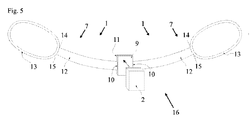
- Figure 5 shows an arrangement 1 for fastening at least one sensor 2 to a face of a subject to acquire a signal indicative of a patient respiratory functions.
- the arrangement 1 comprises at least one ribbon 7, which is stretching, for fastening the sensor 2 to an ear of the subject, when the sensor 2 is placed on a skin below a nose but above the subject's upper lip or mouth.
- the arrangement 1 also comprises a sensor holder 9 having at least one fixing point 10, such as a handle for the stretching ribbon 7 as shown in Figs 2 , 3 and 4 , or the coupling of stretching ribbon 7 and sensor holder 9 may be jointless.
- the stretching ribbon 7 extends around the subject's ear.
- the sensor 2 may be detachably fastened to the sensor holder 9.
- the sensor 2 comprises at least one a detector as shown in Figures 2 , 3 and 4 .
- the sensor 2 may comprise a sensor electronics for signal processing as shown in Figures 2 , 3 and 4 .
- the sensor 2 may be used for instance to acquire a signal indicative of for example a respiratory gas flow, respiratory gas concentration, etc.
- the arrangement further comprises a sticker 11 to glue the sensor holder on a skin of the subject.
- the arrangement 1 may be constructed of inexpensive materials that can be disposed, as they are in straight contact with the patient, which is a benefit in minimizing the risk of cross contaminating between patients.
- the sensor 2 may comprise more expensive electronics that may be reusable.
- the whole measuring assembly 16 comprising the sensor holder 9, the sensor 2 and at least one ribbon 7 is shown in Figure 5 .
Claims (11)
- Messbaugruppe, umfassend:einen Sensor (2) zum Befestigen am Gesicht einer Person zum Erfassen eines Signals, das einen oder mehr physiologische Patientenparameter anzeigt,einen Sensorhalter (9) zum Anordnen des Sensors, aufweisend zumindest einen Befestigungspunkt (10), undzumindest ein Band (7), das dehnbar ist, zum Befestigen des zumindest einen Befestigungspunkts des Sensorhalters an einem Ohr der Person,wobei die Messbaugruppe außerdem einen Aufkleber (11) zum Kleben des Sensorhalters auf die Haut der Person unterhalb der Nase, jedoch oberhalb der Oberlippe oder des Munds der Person umfasst, und wobei der Sensor zumindest einen Detektor (4; 102, 104) zum Erfassen eines Signals umfasst, das eine Atemfunktion anzeigt,
dadurch gekennzeichnet, dass der Sensorhalter (9) außerdem folgendes umfasst:einen ersten Hohlraum (18; 118) mit einer ersten Durchlassöffnung (17; 117), die einen ersten Atmungsgasstrom ermöglicht, und einen zweiten Hohlraum (22; 122) mit einer zweiten Durchlassöffnung (21; 121), die ebenfalls einen Atmungsgasstrom ermöglicht;zumindest eine zusätzliche Durchlassöffnung (31) zum Beseitigen des Atmungsgasstroms, der vom ersten Hohlraum und vom zweiten Hohlraum kommt, wobei die zusätzliche Durchlassöffnung von der ersten Durchlassöffnung und der zweiten Durchlassöffnung separat ist, wobei die zusätzliche Durchlassöffnung mit dem Detektor ausgestattet ist; undeine Stromführung (41), die zum Leiten des Gasstroms von jedem der Hohlräume (18, 22) zu einer Öffnung (32) der zusätzlichen Durchlassöffnung (31) hin und zum Verhindern, dass das Atmungsgas zwischen den Hohlräumen (18, 22) strömt, konfiguriert ist. - Messbaugruppe nach Anspruch 1, dadurch gekennzeichnet, dass der Sensor (2) vom Sensorhalter (9) abnehmbar ist.
- Messbaugruppe nach Anspruch 1, dadurch gekennzeichnet, dass der Sensorhalter (9) und der Sensor (2) eine einstückige Struktur ausbilden.
- Messbaugruppe nach Anspruch 1, dadurch gekennzeichnet, dass der Sensorhalter (9) zumindest zwei Befestigungspunkte (10) umfasst, wobei beide Befestigungspunkte mit separaten Bändern (7) verbindbar sind, welche an verschiedenen Ohren befestigt werden können.
- Messbaugruppe nach Anspruch 1, dadurch gekennzeichnet, dass das Band (7) dazu konfiguriert ist, um das Ohr (8) des Patienten herum zu verlaufen.
- Messbaugruppe nach Anspruch 1, dadurch gekennzeichnet, dass das Band (7) zwei Teile umfasst, wobei das erste Teil (12) im Wesentlichen unelastisch ist, wenn sich das zweite Teil (13) dehnt.
- Messbaugruppe nach Anspruch 6, dadurch gekennzeichnet, dass das zweite Teil (13) des Bands, das sich dehnt, zum Verlaufen um das Ohr (8) der Person konfiguriert ist.
- Messbaugruppe nach Anspruch 6, dadurch gekennzeichnet, dass das erste Teil (12) des Bands, das im Wesentlichen unelastisch ist, zum Verbinden des zweiten Teils (13) des Bands mit dem Befestigungspunkt des Sensorhalters konfiguriert ist.
- Messbaugruppe nach Anspruch 1, dadurch gekennzeichnet, dass das Band ein erstes Ende (14) und ein zweites Ende (15) umfasst, die direkt oder indirekt mit dem Befestigungspunkt (10) des Sensorhalters (9) verbunden sind, sodass das Band eine Schleife bildet, die zum Einkreisen eines Ohrs der Person geeignet ist.
- Messbaugruppe nach Anspruch 6, dadurch gekennzeichnet, dass das zweite Teil (13) des Bands (7) ein erstes Ende (14) und ein zweites Ende (15) umfasst, die direkt oder indirekt mit dem befestigungspunkt (10) des Sensorhalters (9) verbunden sind, sodass das Band eine Schleife bildet, die zum Einkreisen eines Ohrs der Person geeignet ist.
- Messbaugruppe nach Anspruch 6, dadurch gekennzeichnet, dass das erste Teil (13) des Bands (7) breiter als das zweite Teil ist, dessen Querschnitt rund ist.
Priority Applications (3)
| Application Number | Priority Date | Filing Date | Title |
|---|---|---|---|
| EP10153965.8A EP2361552B1 (de) | 2010-02-18 | 2010-02-18 | Anordnung zur Befestigung eines Sensors auf einer Objektvorderseite |
| US13/017,086 US8746090B2 (en) | 2010-02-18 | 2011-01-31 | Arrangement for fastening sensor to face of subject and measuring assembly |
| CN2011100440262A CN102160776A (zh) | 2010-02-18 | 2011-02-18 | 用于将传感器紧固到对象的面部的装置以及测量组件 |
Applications Claiming Priority (1)
| Application Number | Priority Date | Filing Date | Title |
|---|---|---|---|
| EP10153965.8A EP2361552B1 (de) | 2010-02-18 | 2010-02-18 | Anordnung zur Befestigung eines Sensors auf einer Objektvorderseite |
Publications (2)
| Publication Number | Publication Date |
|---|---|
| EP2361552A1 EP2361552A1 (de) | 2011-08-31 |
| EP2361552B1 true EP2361552B1 (de) | 2016-09-14 |
Family
ID=42547253
Family Applications (1)
| Application Number | Title | Priority Date | Filing Date |
|---|---|---|---|
| EP10153965.8A Active EP2361552B1 (de) | 2010-02-18 | 2010-02-18 | Anordnung zur Befestigung eines Sensors auf einer Objektvorderseite |
Country Status (3)
| Country | Link |
|---|---|
| US (1) | US8746090B2 (de) |
| EP (1) | EP2361552B1 (de) |
| CN (1) | CN102160776A (de) |
Families Citing this family (8)
| Publication number | Priority date | Publication date | Assignee | Title |
|---|---|---|---|---|
| US8453649B2 (en) * | 2009-02-18 | 2013-06-04 | 0200L, Llc | Apparatus for positioning a nasal cannula |
| JP2014505532A (ja) | 2010-12-31 | 2014-03-06 | オーツーオーオーエル,エルエルシー | 鼻カニューレの位置決め装置 |
| US10792193B2 (en) * | 2014-07-08 | 2020-10-06 | Kah Medical Supplies, Llc | Nasal drip pad |
| EP3457938B1 (de) * | 2016-05-17 | 2023-07-12 | Dormotech Medical Ltd. | Vorrichtung, system und verfahren zur bewertung von schlafstörungen |
| GB2551768A (en) * | 2016-06-30 | 2018-01-03 | Gen Electric | Method and apparatus for recording respiratory rate |
| US11600365B2 (en) | 2017-12-12 | 2023-03-07 | Vyaire Medical, Inc. | Nasal and oral respiration sensor |
| CN114222527A (zh) | 2019-06-11 | 2022-03-22 | 维亚埃尔医疗股份有限公司 | 呼吸传感器附接装置 |
| US11491295B2 (en) * | 2020-06-16 | 2022-11-08 | Cynthia Quechuleno | Nasal cannula clip system and method |
Citations (1)
| Publication number | Priority date | Publication date | Assignee | Title |
|---|---|---|---|---|
| WO2003000133A1 (en) * | 2001-06-26 | 2003-01-03 | C-Lect Medical Ltd | Respiration monitoring equipment |
Family Cites Families (10)
| Publication number | Priority date | Publication date | Assignee | Title |
|---|---|---|---|---|
| US3658054A (en) * | 1970-05-11 | 1972-04-25 | Gen Technical Services Inc | Adjustable helmet face mask |
| US5284469A (en) * | 1991-11-08 | 1994-02-08 | Dale Medical Products, Inc. | Nasal dressing holder |
| US5983129A (en) * | 1998-02-19 | 1999-11-09 | Cowan; Jonathan D. | Method for determining an individual's intensity of focused attention and integrating same into computer program |
| US7462154B2 (en) * | 2001-03-08 | 2008-12-09 | Nihon Kohden Corporation | Sensor for measuring carbon dioxide in respiratory gas |
| US8328420B2 (en) * | 2003-04-22 | 2012-12-11 | Marcio Marc Abreu | Apparatus and method for measuring biologic parameters |
| US7087027B2 (en) * | 2002-04-22 | 2006-08-08 | Page Thomas C | Device and method for monitoring respiration |
| JP4247758B2 (ja) * | 2003-02-18 | 2009-04-02 | 日本光電工業株式会社 | 炭酸ガス測定センサ |
| WO2008097307A2 (en) * | 2006-01-25 | 2008-08-14 | Kanzer Steve H | Droplet collection devices and methods to detect and control airborne communicable diseases utilizing rfid |
| US8161971B2 (en) * | 2006-08-04 | 2012-04-24 | Ric Investments, Llc | Nasal and oral patient interface |
| WO2009109005A1 (en) * | 2008-03-04 | 2009-09-11 | Resmed Ltd | Unobtrusive interface systems |
-
2010
- 2010-02-18 EP EP10153965.8A patent/EP2361552B1/de active Active
-
2011
- 2011-01-31 US US13/017,086 patent/US8746090B2/en active Active
- 2011-02-18 CN CN2011100440262A patent/CN102160776A/zh active Pending
Patent Citations (1)
| Publication number | Priority date | Publication date | Assignee | Title |
|---|---|---|---|---|
| WO2003000133A1 (en) * | 2001-06-26 | 2003-01-03 | C-Lect Medical Ltd | Respiration monitoring equipment |
Also Published As
| Publication number | Publication date |
|---|---|
| EP2361552A1 (de) | 2011-08-31 |
| US20110197689A1 (en) | 2011-08-18 |
| US8746090B2 (en) | 2014-06-10 |
| CN102160776A (zh) | 2011-08-24 |
Similar Documents
| Publication | Publication Date | Title |
|---|---|---|
| US8746090B2 (en) | Arrangement for fastening sensor to face of subject and measuring assembly | |
| EP2285269B1 (de) | Drahtlose kapnographie | |
| US8475369B2 (en) | Integrated pressure and temperature cannula | |
| EP0654971B1 (de) | Fixationsvorrichtung | |
| EP3723602B1 (de) | Nasaler und oraler atemsensor | |
| US8161971B2 (en) | Nasal and oral patient interface | |
| AU765937B2 (en) | Bio-mask with integral sensors | |
| US8413502B2 (en) | Device for measuring infant feeding performance | |
| US20100256460A1 (en) | Wearable Monitoring System | |
| US20110301484A1 (en) | Adaptive temperature sensor for breath monitoring device | |
| US20090069646A1 (en) | Adaptor for collecting expiratory information and biological information processing system using the same | |
| JP2004537328A (ja) | 医療用の間接カロリーメータ | |
| EP2236080B1 (de) | Sensor | |
| CN205493840U (zh) | 口罩式睡眠呼吸监测仪 | |
| US20090283097A1 (en) | Medical cannula assembly for use with a patient | |
| WO2014193847A1 (en) | Breathing mask for ventilating a patient | |
| CA3140428A1 (en) | Respiration sensor attachment device | |
| IL208995A (en) | Wireless capnography |
Legal Events
| Date | Code | Title | Description |
|---|---|---|---|
| PUAI | Public reference made under article 153(3) epc to a published international application that has entered the european phase |
Free format text: ORIGINAL CODE: 0009012 |
|
| AK | Designated contracting states |
Kind code of ref document: A1 Designated state(s): AT BE BG CH CY CZ DE DK EE ES FI FR GB GR HR HU IE IS IT LI LT LU LV MC MK MT NL NO PL PT RO SE SI SK SM TR |
|
| AX | Request for extension of the european patent |
Extension state: AL BA RS |
|
| 17P | Request for examination filed |
Effective date: 20120228 |
|
| 17Q | First examination report despatched |
Effective date: 20120830 |
|
| GRAP | Despatch of communication of intention to grant a patent |
Free format text: ORIGINAL CODE: EPIDOSNIGR1 |
|
| INTG | Intention to grant announced |
Effective date: 20160412 |
|
| GRAS | Grant fee paid |
Free format text: ORIGINAL CODE: EPIDOSNIGR3 |
|
| GRAA | (expected) grant |
Free format text: ORIGINAL CODE: 0009210 |
|
| AK | Designated contracting states |
Kind code of ref document: B1 Designated state(s): AT BE BG CH CY CZ DE DK EE ES FI FR GB GR HR HU IE IS IT LI LT LU LV MC MK MT NL NO PL PT RO SE SI SK SM TR |
|
| REG | Reference to a national code |
Ref country code: GB Ref legal event code: FG4D |
|
| REG | Reference to a national code |
Ref country code: CH Ref legal event code: EP |
|
| REG | Reference to a national code |
Ref country code: IE Ref legal event code: FG4D |
|
| REG | Reference to a national code |
Ref country code: AT Ref legal event code: REF Ref document number: 828008 Country of ref document: AT Kind code of ref document: T Effective date: 20161015 |
|
| REG | Reference to a national code |
Ref country code: DE Ref legal event code: R096 Ref document number: 602010036357 Country of ref document: DE |
|
| REG | Reference to a national code |
Ref country code: LT Ref legal event code: MG4D |
|
| REG | Reference to a national code |
Ref country code: NL Ref legal event code: MP Effective date: 20160914 |
|
| PG25 | Lapsed in a contracting state [announced via postgrant information from national office to epo] |
Ref country code: FI Free format text: LAPSE BECAUSE OF FAILURE TO SUBMIT A TRANSLATION OF THE DESCRIPTION OR TO PAY THE FEE WITHIN THE PRESCRIBED TIME-LIMIT Effective date: 20160914 Ref country code: HR Free format text: LAPSE BECAUSE OF FAILURE TO SUBMIT A TRANSLATION OF THE DESCRIPTION OR TO PAY THE FEE WITHIN THE PRESCRIBED TIME-LIMIT Effective date: 20160914 Ref country code: NO Free format text: LAPSE BECAUSE OF FAILURE TO SUBMIT A TRANSLATION OF THE DESCRIPTION OR TO PAY THE FEE WITHIN THE PRESCRIBED TIME-LIMIT Effective date: 20161214 Ref country code: LT Free format text: LAPSE BECAUSE OF FAILURE TO SUBMIT A TRANSLATION OF THE DESCRIPTION OR TO PAY THE FEE WITHIN THE PRESCRIBED TIME-LIMIT Effective date: 20160914 |
|
| REG | Reference to a national code |
Ref country code: AT Ref legal event code: MK05 Ref document number: 828008 Country of ref document: AT Kind code of ref document: T Effective date: 20160914 |
|
| REG | Reference to a national code |
Ref country code: FR Ref legal event code: PLFP Year of fee payment: 8 |
|
| PG25 | Lapsed in a contracting state [announced via postgrant information from national office to epo] |
Ref country code: SE Free format text: LAPSE BECAUSE OF FAILURE TO SUBMIT A TRANSLATION OF THE DESCRIPTION OR TO PAY THE FEE WITHIN THE PRESCRIBED TIME-LIMIT Effective date: 20160914 Ref country code: ES Free format text: LAPSE BECAUSE OF FAILURE TO SUBMIT A TRANSLATION OF THE DESCRIPTION OR TO PAY THE FEE WITHIN THE PRESCRIBED TIME-LIMIT Effective date: 20160914 Ref country code: LV Free format text: LAPSE BECAUSE OF FAILURE TO SUBMIT A TRANSLATION OF THE DESCRIPTION OR TO PAY THE FEE WITHIN THE PRESCRIBED TIME-LIMIT Effective date: 20160914 Ref country code: NL Free format text: LAPSE BECAUSE OF FAILURE TO SUBMIT A TRANSLATION OF THE DESCRIPTION OR TO PAY THE FEE WITHIN THE PRESCRIBED TIME-LIMIT Effective date: 20160914 Ref country code: GR Free format text: LAPSE BECAUSE OF FAILURE TO SUBMIT A TRANSLATION OF THE DESCRIPTION OR TO PAY THE FEE WITHIN THE PRESCRIBED TIME-LIMIT Effective date: 20161215 |
|
| PG25 | Lapsed in a contracting state [announced via postgrant information from national office to epo] |
Ref country code: EE Free format text: LAPSE BECAUSE OF FAILURE TO SUBMIT A TRANSLATION OF THE DESCRIPTION OR TO PAY THE FEE WITHIN THE PRESCRIBED TIME-LIMIT Effective date: 20160914 Ref country code: RO Free format text: LAPSE BECAUSE OF FAILURE TO SUBMIT A TRANSLATION OF THE DESCRIPTION OR TO PAY THE FEE WITHIN THE PRESCRIBED TIME-LIMIT Effective date: 20160914 |
|
| PG25 | Lapsed in a contracting state [announced via postgrant information from national office to epo] |
Ref country code: PL Free format text: LAPSE BECAUSE OF FAILURE TO SUBMIT A TRANSLATION OF THE DESCRIPTION OR TO PAY THE FEE WITHIN THE PRESCRIBED TIME-LIMIT Effective date: 20160914 Ref country code: IS Free format text: LAPSE BECAUSE OF FAILURE TO SUBMIT A TRANSLATION OF THE DESCRIPTION OR TO PAY THE FEE WITHIN THE PRESCRIBED TIME-LIMIT Effective date: 20170114 Ref country code: AT Free format text: LAPSE BECAUSE OF FAILURE TO SUBMIT A TRANSLATION OF THE DESCRIPTION OR TO PAY THE FEE WITHIN THE PRESCRIBED TIME-LIMIT Effective date: 20160914 Ref country code: SM Free format text: LAPSE BECAUSE OF FAILURE TO SUBMIT A TRANSLATION OF THE DESCRIPTION OR TO PAY THE FEE WITHIN THE PRESCRIBED TIME-LIMIT Effective date: 20160914 Ref country code: BG Free format text: LAPSE BECAUSE OF FAILURE TO SUBMIT A TRANSLATION OF THE DESCRIPTION OR TO PAY THE FEE WITHIN THE PRESCRIBED TIME-LIMIT Effective date: 20161214 Ref country code: CZ Free format text: LAPSE BECAUSE OF FAILURE TO SUBMIT A TRANSLATION OF THE DESCRIPTION OR TO PAY THE FEE WITHIN THE PRESCRIBED TIME-LIMIT Effective date: 20160914 Ref country code: BE Free format text: LAPSE BECAUSE OF FAILURE TO SUBMIT A TRANSLATION OF THE DESCRIPTION OR TO PAY THE FEE WITHIN THE PRESCRIBED TIME-LIMIT Effective date: 20160914 Ref country code: PT Free format text: LAPSE BECAUSE OF FAILURE TO SUBMIT A TRANSLATION OF THE DESCRIPTION OR TO PAY THE FEE WITHIN THE PRESCRIBED TIME-LIMIT Effective date: 20170116 Ref country code: SK Free format text: LAPSE BECAUSE OF FAILURE TO SUBMIT A TRANSLATION OF THE DESCRIPTION OR TO PAY THE FEE WITHIN THE PRESCRIBED TIME-LIMIT Effective date: 20160914 |
|
| REG | Reference to a national code |
Ref country code: DE Ref legal event code: R097 Ref document number: 602010036357 Country of ref document: DE |
|
| PG25 | Lapsed in a contracting state [announced via postgrant information from national office to epo] |
Ref country code: IT Free format text: LAPSE BECAUSE OF FAILURE TO SUBMIT A TRANSLATION OF THE DESCRIPTION OR TO PAY THE FEE WITHIN THE PRESCRIBED TIME-LIMIT Effective date: 20160914 |
|
| PLBE | No opposition filed within time limit |
Free format text: ORIGINAL CODE: 0009261 |
|
| STAA | Information on the status of an ep patent application or granted ep patent |
Free format text: STATUS: NO OPPOSITION FILED WITHIN TIME LIMIT |
|
| PG25 | Lapsed in a contracting state [announced via postgrant information from national office to epo] |
Ref country code: DK Free format text: LAPSE BECAUSE OF FAILURE TO SUBMIT A TRANSLATION OF THE DESCRIPTION OR TO PAY THE FEE WITHIN THE PRESCRIBED TIME-LIMIT Effective date: 20160914 |
|
| 26N | No opposition filed |
Effective date: 20170615 |
|
| PG25 | Lapsed in a contracting state [announced via postgrant information from national office to epo] |
Ref country code: MC Free format text: LAPSE BECAUSE OF FAILURE TO SUBMIT A TRANSLATION OF THE DESCRIPTION OR TO PAY THE FEE WITHIN THE PRESCRIBED TIME-LIMIT Effective date: 20160914 |
|
| REG | Reference to a national code |
Ref country code: CH Ref legal event code: PL |
|
| PG25 | Lapsed in a contracting state [announced via postgrant information from national office to epo] |
Ref country code: LI Free format text: LAPSE BECAUSE OF NON-PAYMENT OF DUE FEES Effective date: 20170228 Ref country code: CH Free format text: LAPSE BECAUSE OF NON-PAYMENT OF DUE FEES Effective date: 20170228 |
|
| REG | Reference to a national code |
Ref country code: IE Ref legal event code: MM4A |
|
| PG25 | Lapsed in a contracting state [announced via postgrant information from national office to epo] |
Ref country code: SI Free format text: LAPSE BECAUSE OF FAILURE TO SUBMIT A TRANSLATION OF THE DESCRIPTION OR TO PAY THE FEE WITHIN THE PRESCRIBED TIME-LIMIT Effective date: 20160914 |
|
| PG25 | Lapsed in a contracting state [announced via postgrant information from national office to epo] |
Ref country code: LU Free format text: LAPSE BECAUSE OF NON-PAYMENT OF DUE FEES Effective date: 20170218 |
|
| REG | Reference to a national code |
Ref country code: FR Ref legal event code: PLFP Year of fee payment: 9 |
|
| PG25 | Lapsed in a contracting state [announced via postgrant information from national office to epo] |
Ref country code: IE Free format text: LAPSE BECAUSE OF NON-PAYMENT OF DUE FEES Effective date: 20170218 |
|
| PG25 | Lapsed in a contracting state [announced via postgrant information from national office to epo] |
Ref country code: MT Free format text: LAPSE BECAUSE OF NON-PAYMENT OF DUE FEES Effective date: 20170218 |
|
| PG25 | Lapsed in a contracting state [announced via postgrant information from national office to epo] |
Ref country code: HU Free format text: LAPSE BECAUSE OF FAILURE TO SUBMIT A TRANSLATION OF THE DESCRIPTION OR TO PAY THE FEE WITHIN THE PRESCRIBED TIME-LIMIT; INVALID AB INITIO Effective date: 20100218 |
|
| PG25 | Lapsed in a contracting state [announced via postgrant information from national office to epo] |
Ref country code: CY Free format text: LAPSE BECAUSE OF NON-PAYMENT OF DUE FEES Effective date: 20160914 |
|
| PG25 | Lapsed in a contracting state [announced via postgrant information from national office to epo] |
Ref country code: MK Free format text: LAPSE BECAUSE OF FAILURE TO SUBMIT A TRANSLATION OF THE DESCRIPTION OR TO PAY THE FEE WITHIN THE PRESCRIBED TIME-LIMIT Effective date: 20160914 |
|
| PG25 | Lapsed in a contracting state [announced via postgrant information from national office to epo] |
Ref country code: TR Free format text: LAPSE BECAUSE OF FAILURE TO SUBMIT A TRANSLATION OF THE DESCRIPTION OR TO PAY THE FEE WITHIN THE PRESCRIBED TIME-LIMIT Effective date: 20160914 |
|
| PGFP | Annual fee paid to national office [announced via postgrant information from national office to epo] |
Ref country code: FR Payment date: 20230119 Year of fee payment: 14 |
|
| PGFP | Annual fee paid to national office [announced via postgrant information from national office to epo] |
Ref country code: GB Payment date: 20230120 Year of fee payment: 14 Ref country code: DE Payment date: 20230119 Year of fee payment: 14 |
|
| P01 | Opt-out of the competence of the unified patent court (upc) registered |
Effective date: 20230528 |