EP2360838A1 - Method for logarithmic analog-to-digital conversion of an analog input signal and corresponding apparatus - Google Patents
Method for logarithmic analog-to-digital conversion of an analog input signal and corresponding apparatus Download PDFInfo
- Publication number
- EP2360838A1 EP2360838A1 EP11155141A EP11155141A EP2360838A1 EP 2360838 A1 EP2360838 A1 EP 2360838A1 EP 11155141 A EP11155141 A EP 11155141A EP 11155141 A EP11155141 A EP 11155141A EP 2360838 A1 EP2360838 A1 EP 2360838A1
- Authority
- EP
- European Patent Office
- Prior art keywords
- signal
- analog
- digital
- code information
- value
- Prior art date
- Legal status (The legal status is an assumption and is not a legal conclusion. Google has not performed a legal analysis and makes no representation as to the accuracy of the status listed.)
- Granted
Links
Images


Classifications
-
- H—ELECTRICITY
- H03—ELECTRONIC CIRCUITRY
- H03M—CODING; DECODING; CODE CONVERSION IN GENERAL
- H03M1/00—Analogue/digital conversion; Digital/analogue conversion
- H03M1/12—Analogue/digital converters
- H03M1/1235—Non-linear conversion not otherwise provided for in subgroups of H03M1/12
-
- H—ELECTRICITY
- H03—ELECTRONIC CIRCUITRY
- H03M—CODING; DECODING; CODE CONVERSION IN GENERAL
- H03M1/00—Analogue/digital conversion; Digital/analogue conversion
- H03M1/12—Analogue/digital converters
- H03M1/14—Conversion in steps with each step involving the same or a different conversion means and delivering more than one bit
- H03M1/16—Conversion in steps with each step involving the same or a different conversion means and delivering more than one bit with scale factor modification, i.e. by changing the amplification between the steps
Definitions
- the invention relates to the analog / digital conversion of an analog signal, and more particularly to the analog / digital conversion of the logarithmic type, which is particularly useful when the analog signal is representative of a physical quantity (electrical, thermal, etc.). ) through a law of the exponential type.
- the variation in physical quantity corresponding to a variation of a least significant bit in the output digital word delivered by the converter depends on the value of this digital word.
- a new architecture of a logarithmic type analog / digital converter is proposed especially with a wide range of dynamic operation and also offering flexibility of realization.
- a logarithmic type analog / digital converter architecture capable of operating at a low supply voltage with low current consumption and having a reduced size.
- the progressive compression logarithmic amplifier device generates, between each compression amplifier, a voltage which is linear over a short area with respect to the input voltage of the amplifier device when it is expressed in a logarithmic scale.
- a thermometric code is obtained which indicates in which zone the input voltage is located.
- the thermometric code is then converted into a binary code to form the most significant bits of a digital output word. These bits can be considered as "coarse” bits, because resulting from a first so-called “coarse” conversion.
- the temperature code information can also be used to select, through an analog multiplexer, the linear area of one of the generated voltages.
- the voltage thus selected is then digitized through a linear analog / digital converter so as to generate the finer resolution bits of the digital output word delivered by the converter. These bits can then be considered as "fine” bits, because resulting from a second so-called “fine” conversion.
- the value of the reference signal is preferably chosen such that when a secondary signal of rank i in the sequence takes the value equal to the value of the reference signal, the value corresponding of the secondary signal of rank i-1 is in said secondary signal zone of rank i-1.
- the development of the first digital word comprises a conversion of the thermometric code information into an intermediate code information, a bit of rank i of the intermediate code information being obtained from the product the complement of the rank i bit and the rank i-1 bit or its complement, the thermometric code information, and a conversion of the intermediate code information into a bit code information forming said first digital word.
- the method further comprises a selection of one of the secondary signals of the sequence from the information of the thermometric code, a secondary analog / digital conversion of the selected secondary signal, a secondary thermometer code information and a conversion of this secondary thermometer code information into a second digital word, the first and second digital words respectively forming first and second parts of a digital output word, the second part having a lower weight than the first part.
- bits of the first digital word form the so-called “coarse bits” in the output digital word
- bits of the second digital word form the fine bits ("fine”). bits "in English) of the output digital word.
- Said selection of the secondary signal is advantageously performed from the intermediate code information.
- all said linear areas extend at least between a first common lower limit value and a first common upper limit value
- the secondary analog / digital conversion of the selected secondary signal comprises a comparison of the secondary signal with reference thresholds regularly distributed between said first common lower limit value and said first common upper limit value.
- the linearity of the analog-to-digital converter depends on the correlation between the coarse bits and the fine bits, which is notably directly impacted by the accuracy of the comparators making the comparisons with the common reference signal.
- an error in the rough conversion will induce an error on the selected segment, which may lead to the output of the analog multiplexer, which makes the selection, exceeds the conversion range of the secondary analog / digital converter.
- the secondary analog / digital conversion of the selected secondary signal comprises a comparison of the secondary signal with thresholds.
- reference frequency regularly distributed between a second lower limit value lower than said first common lower limit value, and a second upper limit value higher than said first common upper limit value; this amounts to adding comparison thresholds in the conversion range of the secondary analog / digital converter.
- the method then further comprises calibrating said digital analog conversion with a calibration analog signal as an input signal; this calibration signal follows a monotonous time evolution; the method then comprises developing a correspondence table between the first and second digital words successively obtained during the analog / digital conversion of the calibration signal and the desired digital output words forming together a continuous binary digital code.
- a logarithmic analog / digital conversion device comprising input means configured to receive an analog input signal, and processing means connected to the input means.
- the value of the reference signal is chosen such that when a secondary signal of rank i in said sequence takes the value equal to the value of the reference signal, the corresponding value of the secondary signal of rank i-1 is in said zone of this secondary signal of rank i-1.
- the first conversion means comprises a first conversion block configured to convert the thermometric code information into an intermediate code information, a rank i bit of the code information. intermediate being obtained from the complement product of the rank i bit and the rank i-1 bit or its complement of the thermometric code information, and a second conversion block configured to convert the intermediate code information into binary code information forming said first digital word.
- said control input is coupled to the output of the first conversion block.
- all said zones extend at least between a first common lower limit value and a first common upper limit value and the secondary analog / digital conversion means comprise an array of secondary comparators configured to perform a signal comparison.
- secondary school with reference thresholds distributed between said first common lower limit value and said first common upper limit value.
- the secondary means of analog / digital conversion comprise an array of secondary comparators configured to perform a comparison of the secondary signal with reference thresholds regularly distributed between a lower second lower limit value than said first lower common lower limit value. and a second upper limit value higher than said first common upper limit value
- the device further comprises calibration means configured to calibrate the processing means with an analog calibration signal as an input signal this calibration signal following a monotonic time evolution, the calibration means comprising means of elaboration configured to develop a correspondence table between the first and second digital words successively obtained during the analog / digital conversion of the signal of calibration and digital words desired output together forming a continuous binary digital code.
- the reference DIS globally designates an analog / digital conversion device according to the invention.
- This device DIS comprises input means BE for receiving an input analog signal SE, for example an analog voltage Vin.
- the device also comprises an output terminal BS delivering a digital output word MNS corresponding to the input analog signal.
- processing means MT are connected between the input means BE and the output means BS.
- the DIS device is here an analog / digital conversion device of the logarithmic type because the input analog voltage Vin represents, as illustrated on the left side of the figure 2 , a physical quantity, for example electric quantity, thermal, ..., through an exponential law.
- the digital output word MNS is, for example, one of the digital words of the corresponding digital binary code, after analog / digital conversion, at the input analog voltage, and illustrated on the right-hand side of the figure 2 .
- the variation of a least significant bit of an output digital word does not represent the same change in physical quantity depending on whether this least significant bit variation corresponds to a digital word located in the lower part or in the upper part of the binary digital code.
- the DIS device is a logarithmic type analog-to-digital conversion device for which the variation of a least significant bit in a digital word of the output binary digital code represents the same variation in physical quantity whatever the value of this digital output word ( figure 4 ).
- the processing means MT of the device DIS comprise means of logarithmic amplification with progressive compression MAL, of conventional structure and known per se.
- MAL means comprise a chain of several amplifier stages AMP, here 16 amplifier stages, for example class A or AB amplifiers, configured to each deliver a secondary analog signal Vi.
- the means MAL thus deliver 16 secondary analog signals V0-V15.
- transconductance elements TSC are connected between the output of each amplifier stage AMP and the analog output of the means MAL. These transconductance elements perform a voltage-current conversion, the analog output current Iout being equal to the sum of the currents I0-I15 respectively delivered by the transconductance elements TSC.
- the evolution of the values of each secondary analog signal Vi, as a function of the values of the input analog signal Vin comprises a zone Zi corresponding to a linear evolution of the secondary signal Vi as a function of that of the input signal Vin expressed in a logarithmic scale.
- the processing means comprise several comparison means CMP, here comparison means or comparators CMP.
- Each comparator has a first input, here the positive input, a second input, here the negative input, and an output.
- the second inputs of the comparators all receive a common reference signal, namely a common reference voltage Vref.
- the first inputs of the comparators CMP are connected to the outputs of some of the amplifying stages of the amplification means MAL, namely to the outputs of the first 15 stages so as to respectively receive the secondary analog signals V15-V1.
- the binary information T1 to Tn-1 (for example T1 to T15) together form ICDT temperature code information.
- thermometric code is a code in which the digital word formed by the bits T1-Tn-1 is capable of changing from the minimum value, for which all the bits are to zero, at the maximum value, for which all the bits are at 1, by successive passes at 1 of the different bits from the least significant bit to the most significant bit.
- a given weight bit can not be set to 1 if the next lower weight bit has not already been set to 1.
- thermometric By analogy to the gradual rise of mercury in a thermometer.
- the value of the reference signal Vref is chosen such that its value is in each of the linear zones of a secondary signal.
- this value Vref is chosen such that when a secondary signal of rank i takes the value equal to the value of the reference signal, the corresponding value of the secondary signal of rank i-1 is in said linear zone Zi-1 of this secondary signal of rank i-1.
- the reference value Vref is for example a value which lies in the vicinity of the lower value of each linear zone Zi.
- an exemplary embodiment of an AMP amplifier and the transconductance element TSC in differential structure is illustrated on the figure 10 .
- the voltages Vin + and Vin- designate the differential input voltage of the amplifier while the voltages Vout + and Vout-designate the differential output voltage.
- the ICDT temperature code information is converted into a first digital word MN1 ( figure 5 ) via the first conversion means connected to the outputs of the comparison means CMP.
- the first conversion means in fact comprise two conversion stages CV1 and CV2.
- the temperature code information is first converted to an intermediate code and then to a binary code.
- the first converting means therefore comprises a first conversion block CV1 for converting the thermometric code information to an intermediate code information I1-I15, using the equations mentioned on the figure 11 .
- a bit Ii of rank i of the intermediate code information is obtained from the product T i-1 .T i except for the bit I1 which is obtained by the product T 1 .T 2 .
- the conversion block CV1 can be made simply from inverters and AND logic gates.
- the second conversion block CV2 will convert the intermediate code information I1-I15 into the bits, here the four bits B 4 -B 7 , of the first digital word MN1 from the equations illustrated in FIG. figure 11 .
- the CV2 block can be realized simply from OR and NOR logic gates.
- the analog / digital logarithmic converter generates, between each amplifier stage, a secondary analog signal (voltage) which is generally linear over a short section (with respect to the input voltage Vin expressed in a logarithmic scale).
- a thermometric code is obtained which indicates in which section the input voltage is located.
- the thermometric code is then converted to a binary code to form the bits of the first digital word MN1. These bits form "coarse" bits.
- the processing means further comprise multiplexing means MUX having several inputs generally respectively connected to the outputs of the amplifier stages.
- the secondary signal Vn-1 (the signal V15 in the case of the figure 15 ) has a linear area that is too small to be properly exploitable.
- the selection of the V15 signal that should be made when all the bits of T1 to T15 are at 1, is not implemented. This is the case illustrated on the figure 5 .
- the multiplexing means have several inputs respectively connected to the outputs of only some of the amplifier stages, so as to receive only some of the secondary analog signals, namely, in the present case, the V0-V14 signals.
- the multiplexer MUX also comprises an output delivering the signal Vmux_out which will be one of the secondary signals present at the input of the multiplexer MUX.
- the multiplexer MUX also includes an MXEC command input connected to the output of the comparison means CMP.
- T1 is equal to 0, the signal V0 is selected and, if any i, T i is equal to 1, then the signal Vn-1 is selected.
- the selected signal Vmux_out will undergo an analog / digital conversion 140 to form the "fine" bits B0, B1, B2, B3 of a second digital word MN2.
- the digital output word MNS of the logarithmic analog / digital converter is formed of the first digital word MN1 and the second digital word MN2, the bits B0-B3 of the digital word MN2 having a lower weight than the bits B4-B7 of the word digital MN1.
- thermometric information T1-T15 When, as illustrated on the figure 5 it is provided a conversion of thermometric information T1-T15 to the bits of the digital word MN1 in two stages CV1-CV2, the control input the multiplexer MUX is connected directly to the bits 11-115 of the intermediate code, and therefore indirectly to the bits T1-T15 of the thermometric code.
- the multiplexer MUX here comprises PMOS transistors whose gates form the control input of this multiplexer MUX.
- the secondary means of ADC analog / digital conversion then comprise, as illustrated in FIG. figure 16 , a network of RCMPS secondary comparators configured to perform a comparison of the secondary signal selected by the multiplexer MUX with reference thresholds regularly distributed between said values VrefL and VrefH. These Vrefi reference thresholds are delivered at the intermediate nodes of a resistive network RR.
- thermometric code information when the comparison stage CMP and the analog multiplexer MUX do not introduce an error or introduce an error which is considered as acceptable in the application envisaged, it is then sufficient to use, in the example described here , seven secondary comparators CMPS3-CMPS9 delivering seven bits T3-T9 also forming a thermometric code information.
- the reference thresholds Vrefi are regularly distributed between a lower limit value Vref_low lower than the value VrefL of the figure 14 and an upper limit value Vref_high greater than the limit value VrefH of the figure 14 .
- the output of the ADC is converted to 11-bit T1-T11 thermometer code information.
- thermometric code information is, as illustrated in FIG. figure 5 but also on figures 17 and 18 , converted into the second digital word MN2 by two conversion stages CV10 and CV20 forming second conversion means.
- the CV10 stage provides an intermediate code from the thermometric code, using the equations mentioned on the figure 17 while the second conversion stage CV20 transforms the intermediate code I1-I12 into the four bits B0-B3 of the digital word MN2 by means of the equations also mentioned on the figure 17 .
- the four bits B0-B3 do not take all the 16 possible values, but only 12, which corresponds fictitiously to 3.5 bits ( ⁇ 2 3.5 ).
- stages CV10 and CV20 can for example be realized by means of logic circuits comprising inverters and logic gates.
- the linearity of the device DIS depends on the correlation between the coarse bits and the fine bits which results in particular directly from the accuracy of the comparators CMP.
- the Vmux_out output of the MUX multiplexer may exceed the conversion range of the ADC secondary analog-to-digital converter.
- certain segments actually selected may have levels exceeding the VrefH threshold or the VrefL threshold.
- thermometric information T1-T11 This is reflected in the particular embodiment illustrated on the figure 16 by the network of 11 CMPSi secondary comparators delivering the 11 bits of the thermometric information T1-T11.
- an input signal of the processing device MT of the device DIS an input signal SGET (calibration signal) in the form of a monotonic and continuous ramp is applied.
- This ramp can be a linear ramp or an exponential ramp or any monotonous function.
- the code (coarse bits and fine bits) obtained is then stored and a correspondence table is established between the stored code and the desired (continuous) linear code taking into account the code values that should not appear.
- This correspondence table TB thus allows for any digital word of N bit formed coarse bits and fine bits delivered by the processing means MT, to deliver a digital output word MNS on N-1 bit, the set of numerical words output then forming a linear numerical code that is to say continuous.
- the output code contained in the table TB therefore takes all the values between the initial value and the final value.
- code values outside this table are values that should not occur given the evolution of the different segments.
- the value 0001000 corresponding to the values 1010 for the fine bits and the values 0000 for the coarse bits should not occur.
- this code value 001000 now corresponds to the values 0010 of the fine bits and the values 0001 of the coarse bits and makes it possible to ensure the continuity of the numerical code defined by the contents of the table TB.
- a first solution may consist in storing the entire table TB which will output, in the example considered, 7 code bits (the bits C0-C6 of the output word MNS of the figure 5 ) for each combination of coarse bits and fine bits.
- Another solution, more optimized, is simply to store a TB table of smaller size, such as that illustrated on the figure 23 .
- This table TB provides a code of 7 bits for the different values of the coarse bits, the various elements of this table to be added to the fine bits to form the bits of the output word, as illustrated in FIG. figure 24 .
- the 7-bit output word MNS is obtained by summation in SUM summator, bits B0-B3 delivered by conversion stage CV20 and a 7-bit word extracted from table TB which is stored in a ROM.
- the different words stored in the table TB are selected by the value of the bits B4-B7 delivered by the conversion block CV2, which define the addresses in the storage memory.
- the calibration means then comprise a counter configured to count the number of changes in the values of the bits of the digital word MN2 (fine bits).
- the corresponding value of the word MN2 is subtracted, in a subtractor, from the corresponding value of the counter during each change of value of the word MN1 (coarse bits) and the result of this subtraction is stored in the table.
- this calibration procedure can be performed in situ within the DIS itself (it is called auto-calibration) or during the manufacture of the device.
- the device which has just been described has a large dynamic conversion range which depends on the number of amplifiers of the MAL means. As a result, there is a great flexibility of realization which is still important by the optional nature of the elements implementing the fine conversion.
- the frequency bandwidth of the device is only fixed by that of the amplifiers.
- the structure of the device offers a low power consumption under low power supply voltages, for example 1.2 Volts.
- the DIS device which has just been described can also easily be implemented in integrated form within an integrated circuit that can contain other functional blocks. It also has a reduced area, for example less than 0.02 mm 2 in a 65nm CMOS technology.
- FIG. 25 Another example of application of the DIS device is illustrated on the figure 25 .
- the application described here is more particularly aimed at 60 GHz W-HDMI radio frequency architectures and concerns a PA power amplifier regulated by means of a BCL digital control loop operating at 1 MHz.
- the transmission system comprises a DPS detector of the power of the RF out signal delivered by the power amplifier PA, the DIS device described above, a decision block BLD and a digital analog converter DAC. It is thus possible to compensate for a mismatch of the ANT antenna impedance known to those skilled in the art under the name VSWR (Voltage Standing Wave Ratio).
Landscapes
- Engineering & Computer Science (AREA)
- Theoretical Computer Science (AREA)
- Physics & Mathematics (AREA)
- Nonlinear Science (AREA)
- Analogue/Digital Conversion (AREA)
Abstract
Description
L'invention concerne la conversion analogique/numérique d'un signal analogique, et, plus particulièrement, la conversion analogique/numérique du type logarithmique, particulièrement utile lorsque le signal analogique est représentatif d'une quantité physique (électrique, thermique, ...) au travers d'une loi du type exponentiel.The invention relates to the analog / digital conversion of an analog signal, and more particularly to the analog / digital conversion of the logarithmic type, which is particularly useful when the analog signal is representative of a physical quantity (electrical, thermal, etc.). ) through a law of the exponential type.
Avec un convertisseur analogique/numérique linéaire, la variation de quantité physique correspondant à une variation d'un bit de poids faible dans le mot numérique de sortie délivré par le convertisseur dépend de la valeur de ce mot numérique.With a linear analog-to-digital converter, the variation in physical quantity corresponding to a variation of a least significant bit in the output digital word delivered by the converter depends on the value of this digital word.
C'est la raison pour laquelle on utilise de préférence un convertisseur analogique/numérique du type logarithmique dans lequel cette variation d'un bit de poids faible représente la même variation de quantité physique quelle que soit la valeur du mot numérique délivré en sortie du convertisseur.This is the reason why a logarithmic-type analog / digital converter is preferably used in which this variation of a low-order bit represents the same variation in physical quantity whatever the value of the digital word delivered at the output of the converter. .
Il existe de nombreuses structures de convertisseurs analogiques numériques du type logarithmique.There are many structures of digital analog converters of the logarithmic type.
On peut ainsi citer notamment les architectures utilisant un amplificateur opérationnel avec une diode connectée entre la sortie et l'entrée négative de cet amplificateur opérationnel. De tels dispositifs présentent cependant une forte dépendance à la température et une piètre stabilité de boucle qui conduit à une plage dynamique de conversion limitée.It is thus possible to mention in particular the architectures using an operational amplifier with a diode connected between the output and the negative input of this operational amplifier. Such devices, however, have a high temperature dependence and poor loop stability which leads to a limited dynamic range of conversion.
On peut également citer les convertisseurs analogiques/numériques utilisant des architectures pipelinées à capacités commutées. De telles architectures présentent notamment une forte complexité de réalisation et une consommation de courant importante.There are also analog / digital converters using switched capacitor pipelined architectures. Such architectures have in particular a high complexity of implementation and a significant current consumption.
Selon un mode de réalisation, il est proposé notamment une nouvelle architecture de convertisseur analogique/numérique du type logarithmique présentant en particulier une large plage de fonctionnement dynamique et offrant également une flexibilité de réalisation.According to one embodiment, a new architecture of a logarithmic type analog / digital converter is proposed especially with a wide range of dynamic operation and also offering flexibility of realization.
Selon un mode de mise en oeuvre et de réalisation, il est également proposé une architecture de convertisseur analogique/numérique du type logarithmique capable de fonctionner sous une faible tension d'alimentation avec une faible consommation de courant et présentant une taille réduite.According to an embodiment and embodiment, there is also proposed a logarithmic type analog / digital converter architecture capable of operating at a low supply voltage with low current consumption and having a reduced size.
Selon un mode de réalisation et de mise en oeuvre, il est proposé une solution basée sur une compression progressive logarithmique avec, optionnellement, l'utilisation d'un convertisseur analogique/numérique linéaire.According to one embodiment and implementation, there is proposed a solution based on a logarithmic progressive compression with, optionally, the use of a linear analog / digital converter.
Plus précisément, le dispositif amplificateur logarithmique à compression progressive génère, entre chaque amplificateur de compression, une tension qui est linéaire sur une courte zone par rapport à la tension d'entrée du dispositif amplificateur, lorsqu'elle est exprimée dans une échelle logarithmique. En comparant certaines au moins des tensions générées à une référence commune, on obtient un code thermométrique qui indique dans quelle zone est située la tension d'entrée. Le code thermométrique est ensuite converti dans un code binaire pour former les bits de poids fort d'un mot numérique de sortie. Ces bits peuvent être considérés comme des bits « grossiers », car résultant d'une première conversion dite « grossière ».More precisely, the progressive compression logarithmic amplifier device generates, between each compression amplifier, a voltage which is linear over a short area with respect to the input voltage of the amplifier device when it is expressed in a logarithmic scale. By comparing at least some of the generated voltages with a common reference, a thermometric code is obtained which indicates in which zone the input voltage is located. The thermometric code is then converted into a binary code to form the most significant bits of a digital output word. These bits can be considered as "coarse" bits, because resulting from a first so-called "coarse" conversion.
Lorsqu'une précision plus importante est requise, l'information de code thermométrique peut aussi être utilisée pour sélectionner, à travers un multiplexeur analogique, la zone linéaire de l'une des tensions générées. La tension ainsi sélectionnée est ensuite numérisée à travers un convertisseur analogique/numérique linéaire de façon à générer les bits de résolution plus fine du mot numérique de sortie délivré par le convertisseur. Ces bits peuvent être alors considérés comme des bits « fins », car résultant d'une deuxième conversion dite « fine ».When greater precision is required, the temperature code information can also be used to select, through an analog multiplexer, the linear area of one of the generated voltages. The voltage thus selected is then digitized through a linear analog / digital converter so as to generate the finer resolution bits of the digital output word delivered by the converter. These bits can then be considered as "fine" bits, because resulting from a second so-called "fine" conversion.
Ainsi, selon un aspect, il est proposé un procédé de conversion analogique numérique du type logarithmique d'un signal analogique d'entrée, ladite conversion comprenant :
- une amplification logarithmique à compression progressive du signal d'entrée délivrant une séquence de plusieurs signaux analogiques secondaires, l'évolution des valeurs de certains au moins des signaux secondaires en fonction des valeurs du signal analogique d'entrée comportant des zones correspondant à une évolution linéaire desdits signaux secondaires en fonction de celle du signal d'entrée exprimée dans une échelle logarithmique,
- une comparaison de certains au moins des signaux secondaires de ladite séquence avec un signal de référence commun dont la valeur se situe dans chacune desdites zones, fournissant une information de code thermométrique, et
- une élaboration d'un premier mot numérique à partir de l'information de code thermométrique.
- a logarithmic amplification with progressive compression of the input signal delivering a sequence of a plurality of secondary analog signals, the evolution of the values of at least some of the secondary signals as a function of the values of the input analog signal comprising zones corresponding to a linear evolution said secondary signals as a function of that of the input signal expressed in a logarithmic scale,
- comparing at least some of the secondary signals of said sequence with a common reference signal whose value is in each of said areas, providing a thermometric code information, and
- developing a first digital word from the thermometric code information.
De façon à utiliser au maximum ladite zone linéaire de chaque signal secondaire, la valeur du signal de référence est préférentiellement choisie telle que lorsqu'un signal secondaire de rang i dans la séquence prend la valeur égale à la valeur du signal de référence, la valeur correspondante du signal secondaire de rang i-1 se situe dans ladite zone de signal secondaire de rang i-1.In order to make maximum use of said linear zone of each secondary signal, the value of the reference signal is preferably chosen such that when a secondary signal of rank i in the sequence takes the value equal to the value of the reference signal, the value corresponding of the secondary signal of rank i-1 is in said secondary signal zone of rank i-1.
Ainsi, en pratique, on pourra par exemple choisir une valeur de référence se situant au voisinage de la valeur inférieure de chaque zone.Thus, in practice, it may for example choose a reference value located in the vicinity of the lower value of each zone.
Selon un mode de mise en oeuvre, l'élaboration du premier mot numérique comprend une conversion de l'information de code thermométrique en une information de code intermédiaire, un bit de rang i de l'information de code intermédiaire étant obtenu à partir du produit du complément du bit de rang i et du bit de rang i-1 ou de son complément, de l'information de code thermométrique, et une conversion de l'information de code intermédiaire en une information de code binaire formant ledit premier mot numérique.According to one embodiment, the development of the first digital word comprises a conversion of the thermometric code information into an intermediate code information, a bit of rank i of the intermediate code information being obtained from the product the complement of the rank i bit and the rank i-1 bit or its complement, the thermometric code information, and a conversion of the intermediate code information into a bit code information forming said first digital word.
Lorsqu'on souhaite améliorer la résolution de la conversion analogique numérique, il est prévu, selon un mode de mise en oeuvre, que le procédé comprenne en outre une sélection de l'un des signaux secondaires de la séquence à partir de l'information de code thermométrique, une conversion analogique/numérique secondaire du signal secondaire sélectionné, une information secondaire de code thermométrique et une conversion de cette information secondaire de code thermométrique en un deuxième mot numérique, les premier et deuxième mots numériques formant respectivement des première et deuxième parties d'un mot numérique de sortie, la deuxième partie ayant un poids plus faible que la première partie.When it is desired to improve the resolution of the digital analog conversion, it is provided, according to an embodiment, that the method further comprises a selection of one of the secondary signals of the sequence from the information of the thermometric code, a secondary analog / digital conversion of the selected secondary signal, a secondary thermometer code information and a conversion of this secondary thermometer code information into a second digital word, the first and second digital words respectively forming first and second parts of a digital output word, the second part having a lower weight than the first part.
En d'autres termes, les bits du premier mot numérique forment les bits dits « grossiers » (« coarse bits », en langue anglaise) du mot numérique de sortie, tandis que les bits du deuxième mot numérique forment les bits fins (« fine bits » en langue anglaise) du mot numérique de sortie.In other words, the bits of the first digital word form the so-called "coarse bits" in the output digital word, while the bits of the second digital word form the fine bits ("fine"). bits "in English) of the output digital word.
Ladite sélection du signal secondaire est avantageusement effectuée à partir de l'information de code intermédiaire.Said selection of the secondary signal is advantageously performed from the intermediate code information.
Selon un mode de mise en oeuvre, toutes lesdites zones linéaires s'étendent au moins entre une première valeur limite inférieure commune et une première valeur limite supérieure commune, et la conversion analogique/numérique secondaire du signal secondaire sélectionné comprend une comparaison du signal secondaire avec des seuils de référence régulièrement répartis entre ladite première valeur limite inférieure commune et ladite première valeur limite supérieure commune.According to one embodiment, all said linear areas extend at least between a first common lower limit value and a first common upper limit value, and the secondary analog / digital conversion of the selected secondary signal comprises a comparison of the secondary signal with reference thresholds regularly distributed between said first common lower limit value and said first common upper limit value.
Cela étant, la linéarité du convertisseur analogique/numérique dépend de la corrélation entre les bits grossiers et les bits fins, qui est notamment directement impactée par la précision des comparateurs effectuant les comparaisons avec le signal de référence commun.However, the linearity of the analog-to-digital converter depends on the correlation between the coarse bits and the fine bits, which is notably directly impacted by the accuracy of the comparators making the comparisons with the common reference signal.
En d'autres termes, une erreur dans la conversion grossière va induire une erreur sur le segment sélectionné, pouvant conduire à ce que la sortie du multiplexeur analogique, qui effectue la sélection, excède la plage de conversion du convertisseur analogique/numérique secondaire.In other words, an error in the rough conversion will induce an error on the selected segment, which may lead to the output of the analog multiplexer, which makes the selection, exceeds the conversion range of the secondary analog / digital converter.
Pour remédier à ce problème, il est proposé d'augmenter la plage de conversion du convertisseur analogique/numérique secondaire en ajoutant des seuils de référence supplémentaires.To remedy this problem, it is proposed to increase the conversion range of the secondary analog / digital converter by adding additional reference thresholds.
Il devient alors nécessaire de corréler les bits fins aux bits grossiers pour former un unique code numérique de sortie continu.It then becomes necessary to correlate the fine bits to the coarse bits to form a single continuous output digital code.
En d'autres termes, lorsque certaines applications nécessitent de compenser de telles erreurs éventuelles, il est avantageusement prévu, selon un mode de mise en oeuvre, que la conversion analogique/numérique secondaire du signal secondaire sélectionné comprenne une comparaison du signal secondaire avec des seuils de référence régulièrement répartis entre une deuxième valeur limite inférieure plus faible que ladite première valeur limite inférieure commune, et une deuxième valeur limite supérieure plus élevée que ladite première valeur limite supérieure commune ; ceci revient à rajouter des seuils de comparaison dans la plage de conversion du convertisseur analogique/numérique secondaire.In other words, when certain applications need to compensate for such possible errors, it is advantageously provided, according to one embodiment, for the secondary analog / digital conversion of the selected secondary signal to comprise a comparison of the secondary signal with thresholds. reference frequency regularly distributed between a second lower limit value lower than said first common lower limit value, and a second upper limit value higher than said first common upper limit value; this amounts to adding comparison thresholds in the conversion range of the secondary analog / digital converter.
Le procédé comprend alors en outre un étalonnage de ladite conversion analogique numérique avec un signal analogique d'étalonnage en tant que signal d'entrée ; ce signal d'étalonnage suit une évolution temporelle monotone ;
le procédé comprend alors une élaboration d'une table de correspondance entre les premier et deuxième mots numériques successivement obtenus lors de la conversion analogique/numérique du signal d'étalonnage et des mots numériques de sortie désirés formant ensemble un code numérique binaire continu.The method then further comprises calibrating said digital analog conversion with a calibration analog signal as an input signal; this calibration signal follows a monotonous time evolution;
the method then comprises developing a correspondence table between the first and second digital words successively obtained during the analog / digital conversion of the calibration signal and the desired digital output words forming together a continuous binary digital code.
Selon un autre aspect, il est proposé un dispositif de conversion analogique/numérique logarithmique, comportant des moyens d'entrée configurés pour recevoir un signal d'entrée analogique, et des moyens de traitement connectés aux moyens d'entrée.According to another aspect, there is provided a logarithmic analog / digital conversion device, comprising input means configured to receive an analog input signal, and processing means connected to the input means.
Selon une caractéristique générale de cet aspect, les moyens de traitement comprennent des moyens d'amplification logarithmique à compression progressive connectés aux moyens d'entrée et comportant
- une chaîne de plusieurs étages amplificateurs configurés pour délivrer chacun un signal analogique secondaire, l'évolution des valeurs de certains au moins des signaux analogiques secondaires en fonction des valeurs du signal analogique d'entrée comportant des zones correspondant à une évolution linéaire desdits signaux secondaires en fonction de celle du signal d'entrée exprimée dans une échelle logarithmique,
- plusieurs moyens de comparaison possédant respectivement plusieurs premières entrées respectivement connectées aux sorties de certains au moins des étages amplificateurs, plusieurs deuxièmes entrées configurées pour recevoir chacune un signal de référence commun dont la valeur se situe dans chacune desdites zones, et plusieurs sorties configurées pour délivrer une information de code thermométrique,
- des premiers moyens de conversion connectés aux sorties des moyens de comparaison et configurés pour délivrer un premier mot numérique à partir de l'information de code thermométrique.
- a chain of several amplifying stages configured to deliver each a secondary analog signal, the evolution of the values of at least some of the secondary analog signals as a function of the values of the input analog signal comprising areas corresponding to a linear evolution of said secondary signals into according to that of the input signal expressed in a logarithmic scale,
- a plurality of comparison means respectively having a plurality of first inputs respectively connected to the outputs of at least one of the amplifier stages, a plurality of second inputs configured to each receive a common reference signal whose value is in each of said zones, and a plurality of outputs configured to output a thermometric code information,
- first converting means connected to the outputs of the comparing means and configured to output a first digital word from the thermometric code information.
Selon un mode de réalisation, la valeur du signal de référence est choisie telle que lorsqu'un signal secondaire de rang i dans ladite séquence prend la valeur égale à la valeur du signal de référence, la valeur correspondante du signal secondaire de rang i-1 se situe dans ladite zone de ce signal secondaire de rang i-1.According to one embodiment, the value of the reference signal is chosen such that when a secondary signal of rank i in said sequence takes the value equal to the value of the reference signal, the corresponding value of the secondary signal of rank i-1 is in said zone of this secondary signal of rank i-1.
Selon un mode de réalisation, les premiers moyens de conversion comprennent un premier bloc de conversion configuré pour convertir l'information de code thermométrique en une information de code intermédiaire, un bit de rang i de l'information de code intermédiaire étant obtenu à partir du produit du complément du bit de rang i et du bit de rang i-1 ou de son complément de l'information de code thermométrique, et un deuxième bloc de conversion configuré pour convertir l'information de code intermédiaire en une information de code binaire formant ledit premier mot numérique.According to one embodiment, the first conversion means comprises a first conversion block configured to convert the thermometric code information into an intermediate code information, a rank i bit of the code information. intermediate being obtained from the complement product of the rank i bit and the rank i-1 bit or its complement of the thermometric code information, and a second conversion block configured to convert the intermediate code information into binary code information forming said first digital word.
Selon un mode de réalisation, les moyens de traitement comprennent en outre
- des moyens de multiplexage possédant plusieurs entrées respectivement connectées aux sorties de certains au moins des étages amplificateurs, une sortie et une entrée de commande connectée aux sorties des moyens de comparaison,
- des moyens secondaires de conversion analogique/numérique connectés à la sortie des moyens de multiplexage et configurés pour délivrer une information secondaire de code thermométrique, et
- des deuxièmes moyens de conversion configurés pour convertir l'information secondaire de code thermométrique en un deuxième mot numérique à partir du signal secondaire sélectionné délivré à la sortie des moyens de multiplexage, les premier et deuxième mots numériques formant respectivement des première et deuxième parties d'un mot numérique de sortie, la deuxième partie ayant un poids plus faible que la première partie.
- multiplexing means having a plurality of inputs respectively connected to the outputs of at least one of the amplifier stages, an output and a control input connected to the outputs of the comparing means,
- secondary means of analog / digital conversion connected to the output of the multiplexing means and configured to deliver secondary information of the thermometric code, and
- second converting means configured to convert the secondary thermometer code information into a second digital word from the selected secondary signal outputted from the output of the multiplexing means, the first and second digital words respectively forming first and second portions of a digital output word, the second part having a lower weight than the first part.
Selon un mode de réalisation, ladite entrée de commande est couplée à la sortie du premier bloc de conversion.According to one embodiment, said control input is coupled to the output of the first conversion block.
Selon un mode de réalisation, toutes lesdites zones s'étendent au moins entre une première valeur limite inférieure commune et une première valeur limite supérieure commune et les moyens secondaires de conversion analogique/numérique comprennent un réseau de comparateurs secondaires configurés pour effectuer une comparaison du signal secondaire avec des seuils de référence régulièrement répartis entre ladite première valeur limite inférieure commune et ladite première valeur limite supérieure commune.According to one embodiment, all said zones extend at least between a first common lower limit value and a first common upper limit value and the secondary analog / digital conversion means comprise an array of secondary comparators configured to perform a signal comparison. secondary school with reference thresholds distributed between said first common lower limit value and said first common upper limit value.
Selon un mode de réalisation, les moyens secondaires de conversion analogique/numérique comprennent un réseau de comparateurs secondaires configurés pour effectuer une comparaison du signal secondaire avec des seuils de référence régulièrement répartis entre une deuxième valeur limite inférieure plus faible que ladite première valeur limite inférieure commune et une deuxième valeur limite supérieure plus élevée que ladite première valeur limite supérieure commune, et le dispositif comprend en outre des moyens d'étalonnage configurés pour effectuer un étalonnage des moyens de traitement avec un signal analogique d'étalonnage en tant que signal d'entrée, ce signal d'étalonnage suivant une évolution temporelle monotone, les moyens d'étalonnage comportant des moyens d'élaboration configurés pour élaborer une table de correspondance entre les premiers et deuxièmes mots numériques successivement obtenus lors de la conversion analogique/numérique du signal d'étalonnage et des mots numériques de sortie désirés formant ensemble un code numérique binaire continu.According to one embodiment, the secondary means of analog / digital conversion comprise an array of secondary comparators configured to perform a comparison of the secondary signal with reference thresholds regularly distributed between a lower second lower limit value than said first lower common lower limit value. and a second upper limit value higher than said first common upper limit value, and the device further comprises calibration means configured to calibrate the processing means with an analog calibration signal as an input signal this calibration signal following a monotonic time evolution, the calibration means comprising means of elaboration configured to develop a correspondence table between the first and second digital words successively obtained during the analog / digital conversion of the signal of calibration and digital words desired output together forming a continuous binary digital code.
D'autres avantages et caractéristiques de l'invention apparaîtront à l'examen de la description détaillée de modes de mise en oeuvre et de réalisation, nullement limitatifs, et des dessins annexés, sur lesquels :
- la
figure 1 illustre très schématiquement un mode de réalisation d'un dispositif de conversion analogique/numérique selon l'invention, - la
figure 2 illustre une évolution du type exponentiel d'une tension analogique représentant une quantité physique ainsi qu'un code numérique binaire résultant de la conversion de cette tension analogique, - les
figures 3 et 4 illustrent schématiquement des variations d'un bit de poids faible par rapport à une variation de quantité physique dans un convertisseur analogique/numérique linéaire et dans un convertisseur analogique/numérique du type logarithmique, respectivement,
- la
figure 5 illustre de façon plus détaillée, mais toujours schématique, un mode de réalisation d'un dispositif selon l'invention, - les
figures 6 à 18 illustrent plus en détail différentes parties du dispositif de lafigure 5 ainsi que différents modes de mise en oeuvre d'un procédé de conversion analogique/numérique selon l'invention, - les
figures 19 à 24 illustrent schématiquement un autre mode de réalisation et un autre mode de mise en oeuvre de l'invention, et - la
figure 25 illustre schématiquement un exemple d'application d'un dispositif de conversion analogique/numérique selon l'invention.
- the
figure 1 illustrates very schematically an embodiment of an analog / digital conversion device according to the invention, - the
figure 2 illustrates an evolution of the exponential type of an analog voltage representing a physical quantity as well as a binary digital code resulting from the conversion of this analog voltage, - the
figures 3 and4 schematically illustrate variations of a least significant bit with respect to a change in physical quantity in a linear analog / digital converter and in a analog / digital converter of the logarithmic type, respectively,
- the
figure 5 illustrates in more detail, but always diagrammatically, an embodiment of a device according to the invention, - the
Figures 6 to 18 illustrate in more detail different parts of the device of thefigure 5 as well as different modes of implementation of an analog / digital conversion method according to the invention, - the
Figures 19 to 24 schematically illustrate another embodiment and another embodiment of the invention, and - the
figure 25 schematically illustrates an example of application of an analog / digital conversion device according to the invention.
Sur la
Le dispositif comporte également une borne de sortie BS délivrant un mot numérique de sortie MNS correspondant au signal analogique d'entrée. Enfin, des moyens de traitement MT sont connectés entre les moyens d'entrée BE et les moyens de sortie BS.The device also comprises an output terminal BS delivering a digital output word MNS corresponding to the input analog signal. Finally, processing means MT are connected between the input means BE and the output means BS.
Le dispositif DIS est ici un dispositif de conversion analogique/numérique du type logarithmique car la tension analogique d'entrée Vin représente, comme illustré sur la partie gauche de la
Comme illustré sur la
C'est la raison pour laquelle le dispositif DIS est un dispositif de conversion analogique numérique du type logarithmique pour lequel la variation d'un bit de poids faible dans un mot numérique du code numérique binaire de sortie représente la même variation de quantité physique quelle que soit la valeur de ce mot numérique de sortie (
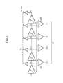
Comme illustré sur la
Ces moyens MAL comportent une chaîne de plusieurs étages amplificateurs AMP, ici 16 étages amplificateurs, par exemple des amplificateurs de classe A ou AB, configurés pour délivrer chacun un signal analogique secondaire Vi. Dans l'exemple décrit ici, les moyens MAL délivrent donc 16 signaux analogiques secondaires V0-V15.These MAL means comprise a chain of several amplifier stages AMP, here 16 amplifier stages, for example class A or AB amplifiers, configured to each deliver a secondary analog signal Vi. In the example described here, the means MAL thus deliver 16 secondary analog signals V0-V15.
De façon classique, des éléments transconducteurs TSC sont connectés entre la sortie de chaque étage amplificateur AMP et la sortie analogique des moyens MAL. Ces éléments transconducteurs effectuent une conversion tension-courant, le courant analogique de sortie Iout étant égal à la somme des courants I0-I15 respectivement délivrés par les éléments transconducteurs TSC.In conventional manner, transconductance elements TSC are connected between the output of each amplifier stage AMP and the analog output of the means MAL. These transconductance elements perform a voltage-current conversion, the analog output current Iout being equal to the sum of the currents I0-I15 respectively delivered by the transconductance elements TSC.
Généralement, comme illustré plus précisément sur la
Outre ces moyens d'amplification logarithmique à compression progressive MAL, les moyens de traitement comprennent plusieurs moyens de comparaison CMP, ici 15 moyens de comparaison ou comparateurs CMP.In addition to these means of logarithmic amplification with progressive compression MAL, the processing means comprise several comparison means CMP, here comparison means or comparators CMP.
Chaque comparateur comporte une première entrée, ici l'entrée positive, une deuxième entrée, ici l'entrée négative, ainsi qu'une sortie.Each comparator has a first input, here the positive input, a second input, here the negative input, and an output.
Les deuxièmes entrées des comparateurs reçoivent toutes un signal de référence commun, à savoir une tension de référence commune Vref.The second inputs of the comparators all receive a common reference signal, namely a common reference voltage Vref.
Les premières entrées des comparateurs CMP sont connectées quant à elles aux sorties de certains des étages amplificateurs des moyens d'amplification MAL, à savoir aux sorties des 15 premiers étages de façon à recevoir respectivement les signaux analogiques secondaires V15-V1.The first inputs of the comparators CMP are connected to the outputs of some of the amplifying stages of the amplification means MAL, namely to the outputs of the first 15 stages so as to respectively receive the secondary analog signals V15-V1.
Lorsque, comme c'est le cas ici, on utilise au sein des moyens de traitement, comme on le verra plus en détail ci après, un convertisseur analogique/numérique secondaire ADC pour fournir les bits fins du mot numérique de sortie, il n'est nullement besoin de prévoir un seizième comparateur CMP qui serait destiné à comparer le signal secondaire V0 avec la tension de référence commune Vref car dans une telle application, l'information ainsi obtenue correspond au seuil minimum de conversion et est alors redondante avec l'information fournie par ce convertisseur analogique/numérique secondaire.When, as is the case here, it is used within the processing means, as will be seen in more detail below, a secondary analog / digital converter ADC to provide the fine bits of the digital output word, it does not matter. there is no need to provide a sixteenth comparator CMP which would be intended to compare the secondary signal V0 with the common reference voltage Vref because in such an application, the information thus obtained corresponds to the minimum conversion threshold and is then redundant with the information provided by this secondary analog / digital converter.
Comme illustré sur la
Plus précisément, lorsque le signal analogique secondaire Vi est supérieur à la tension de référence commune Vref, le bit correspondant Ti prend la valeur logique 1.More precisely, when the secondary analog signal Vi is greater than the common reference voltage Vref, the corresponding bit Ti takes the
On rappelle ici qu'un code thermométrique est un code dans lequel le mot numérique formé des bits T1-Tn-1 est susceptible d'évoluer de la valeur minimale, pour laquelle tous les bits sont à zéro, à la valeur maximale, pour laquelle tous les bits sont à 1, par des passages successifs à 1 des différents bits depuis le bit de poids faible jusqu'au bit de poids fort.It will be recalled here that a thermometric code is a code in which the digital word formed by the bits T1-Tn-1 is capable of changing from the minimum value, for which all the bits are to zero, at the maximum value, for which all the bits are at 1, by successive passes at 1 of the different bits from the least significant bit to the most significant bit.
En d'autres termes, un bit de poids donné ne peut pas passer à 1 si le bit de poids immédiatement inférieur n'est pas déjà passé à 1.In other words, a given weight bit can not be set to 1 if the next lower weight bit has not already been set to 1.
Un tel code est appelé « thermométrique » par analogie à la montée progressive du mercure dans un thermomètre.Such a code is called "thermometric" by analogy to the gradual rise of mercury in a thermometer.
Comme illustré sur la
Par ailleurs, de façon à optimiser l'utilisation des zones linéaires Zi, cette valeur Vref est choisie telle que lorsqu'un signal secondaire de rang i prend la valeur égale à la valeur du signal de référence, la valeur correspondante du signal secondaire de rang i-1 se situe dans ladite zone linéaire Zi-1 de ce signal secondaire de rang i-1.Moreover, in order to optimize the use of the linear zones Zi, this value Vref is chosen such that when a secondary signal of rank i takes the value equal to the value of the reference signal, the corresponding value of the secondary signal of rank i-1 is in said linear zone Zi-1 of this secondary signal of rank i-1.
En pratique, la valeur de référence Vref est par exemple une valeur qui se situe au voisinage de la valeur inférieure de chaque zone linéaire Zi.In practice, the reference value Vref is for example a value which lies in the vicinity of the lower value of each linear zone Zi.
Comme il est classique et connu en soi, un exemple de réalisation d'un amplificateur AMP et de l'élément transconducteur TSC en structure différentielle, est illustré sur la
L'information de code thermométrique ICDT est convertie en un premier mot numérique MN1 (
Plus précisément, dans ce mode de réalisation, les premiers moyens de conversion comportent en fait deux étages de conversion CV1 et CV2.More specifically, in this embodiment, the first conversion means in fact comprise two conversion stages CV1 and CV2.
En effet, comme illustré sur la
Les premiers moyens de conversion comprennent par conséquent un premier bloc de conversion CV1 pour convertir l'information de code thermométrique en une information de code intermédiaire I1-I15, en utilisant les équations mentionnées sur la
Plus précisément, un bit Ii de rang i de l'information de code intermédiaire est obtenu à partir du produit Ti-1.Ti sauf en ce qui concerne le bit I1 qui est obtenu par le produit T1.T2. More specifically, a bit Ii of rank i of the intermediate code information is obtained from the product T i-1 .T i except for the bit I1 which is obtained by the product T 1 .T 2 .
Comme illustré sur la
Le deuxième bloc de conversion CV2 va convertir l'information de code intermédiaire I1-I15 en les bits, ici les quatre bits B4-B7, du premier mot numérique MN1 à partir des équations illustrées sur la
Là encore, comme illustré sur la
Ainsi, le convertisseur analogique/numérique logarithmique génère, entre chaque étage amplificateur, un signal analogique secondaire (tension) qui est généralement linéaire sur une courte section (par rapport à la tension d'entrée Vin exprimée dans une échelle logarithmique). En comparant toutes les tensions ainsi générées à une tension de référence, on obtient un code thermométrique qui indique dans quelle section est située la tension d'entrée. Le code thermométrique est ensuite converti en un code binaire pour former les bits du premier mot numérique MN1. Ces bits forment des bits « grossiers ».Thus, the analog / digital logarithmic converter generates, between each amplifier stage, a secondary analog signal (voltage) which is generally linear over a short section (with respect to the input voltage Vin expressed in a logarithmic scale). By comparing all the voltages thus generated to a reference voltage, a thermometric code is obtained which indicates in which section the input voltage is located. The thermometric code is then converted to a binary code to form the bits of the first digital word MN1. These bits form "coarse" bits.
Cela étant, lorsque dans certaines applications, il est nécessaire d'avoir une résolution plus fine, il est prévu, comme illustré sur la
C'est le cas illustré sur la
Cela étant, dans certaines implémentations pratiques, il est possible que le signal secondaire Vn-1 (le signal V15 dans le cas de la
Ainsi, dans ce cas, les moyens de multiplexage possèdent plusieurs entrées respectivement connectées aux sorties de certains seulement des étages amplificateurs, de façon à recevoir certains seulement des signaux analogiques secondaires, à savoir, dans le cas présent, les signaux V0-V14.Thus, in this case, the multiplexing means have several inputs respectively connected to the outputs of only some of the amplifier stages, so as to receive only some of the secondary analog signals, namely, in the present case, the V0-V14 signals.
Le multiplexeur MUX comporte également une sortie délivrant le signal Vmux_out qui va être l'un des signaux secondaires présents à l'entrée du multiplexeur MUX.The multiplexer MUX also comprises an output delivering the signal Vmux_out which will be one of the secondary signals present at the input of the multiplexer MUX.
Le multiplexeur MUX comporte également une entrée de commande MXEC reliée à la sortie des moyens de comparaison CMP.The multiplexer MUX also includes an MXEC command input connected to the output of the comparison means CMP.
Ainsi, comme illustré sur la
Si T1 est égal à 0, on sélectionne le signal V0 et, si quel que soit i, Ti est égal à 1, alors on sélectionne le signal Vn-1.If T1 is equal to 0, the signal V0 is selected and, if any i, T i is equal to 1, then the signal Vn-1 is selected.
Puis, le signal sélectionné Vmux_out va subir une conversion analogique/numérique 140 pour former les bits « fins » B0, B1, B2, B3 d'un deuxième mot numérique MN2.Then, the selected signal Vmux_out will undergo an analog /
Ainsi, le mot numérique de sortie MNS du convertisseur analogique/numérique logarithmique est formé du premier mot numérique MN1 et du deuxième mot numérique MN2, les bits B0-B3 du mot numérique MN2 ayant un poids plus faible que les bits B4-B7 du mot numérique MN1.Thus, the digital output word MNS of the logarithmic analog / digital converter is formed of the first digital word MN1 and the second digital word MN2, the bits B0-B3 of the digital word MN2 having a lower weight than the bits B4-B7 of the word digital MN1.
Lorsque, comme illustré sur la
Un exemple de réalisation du multiplexeur MUX est alors illustré sur la
Lorsque notamment l'étage de comparateurs CMP est suffisamment précis, toutes les zones « linéaires » des signaux secondaires analogiques Vi s'étendent, comme illustré sur la
Les moyens secondaires de conversion analogique/numérique ADC comprennent alors, comme illustré sur la
Et, lorsque l'étage de comparaison CMP et le multiplexeur analogique MUX n'introduisent pas d'erreur ou introduisent une erreur qui est considérée comme acceptable dans l'application envisagée, il est alors suffisant d'utiliser, dans l'exemple décrit ici, sept comparateurs secondaires CMPS3-CMPS9 délivrant sept bits T3-T9 formant également une information de code thermométrique.And, when the comparison stage CMP and the analog multiplexer MUX do not introduce an error or introduce an error which is considered as acceptable in the application envisaged, it is then sufficient to use, in the example described here , seven secondary comparators CMPS3-CMPS9 delivering seven bits T3-T9 also forming a thermometric code information.
Cela étant, lorsqu'on souhaite prendre en compte l'imprécision générée par les comparateurs CMP et le multiplexeur analogique MUX, il est préférable, comme illustré sur la
Ceci revient à rajouter aux extrémités de l'échelle de conversion, des niveaux de seuils supplémentaires matérialisés ici par quatre comparateurs secondaires supplémentaires, à savoir les comparateurs secondaires CMPS1, CMPS2 et CMPS10, CMPS11.This amounts to adding, at the ends of the conversion scale, additional threshold levels embodied here by four additional secondary comparators, namely the secondary comparators CMPS1, CMPS2 and CMPS10, CMPS11.
Il devient alors nécessaire, comme on le verra plus en détail ci après, d'effectuer une procédure d'étalonnage de façon à ce que l'ensemble des mots numériques de sortie désirés forment ensemble un code numérique binaire continu. On reviendra plus en détail ci après sur cet aspect.It then becomes necessary, as will be seen in more detail below, to perform a calibration procedure so that the set of desired output digital words together form a continuous binary digital code. We will come back in more detail later on this aspect.
Donc, comme illustré sur la
D'une façon analogue à ce qui a été décrit précédemment, cette information de code thermométrique T1-T11 est, comme illustré sur la
Plus précisément, l'étage CV10 fournit un code intermédiaire à partir du code thermométrique, en utilisant les équations mentionnées sur la
Matériellement, comme illustré sur la
On revient maintenant, en se référant plus particulièrement aux
La linéarité du dispositif DIS dépend de la corrélation entre les bits grossiers et les bits fins qui résulte notamment directement de la précision des comparateurs CMP.The linearity of the device DIS depends on the correlation between the coarse bits and the fine bits which results in particular directly from the accuracy of the comparators CMP.
Plus précisément, comme illustré sur la
En effet, comme illustré sur la
C'est la raison pour laquelle, afin de résoudre ce problème, on prévoit, comme illustré sur la
Ceci se traduit dans l'exemple particulier de réalisation illustré sur la
Cela étant, certaines valeurs de code n'apparaîtront jamais en raison de l'adjonction de ces niveaux de seuils supplémentaires de conversion.However, some code values will never appear because of the addition of these additional conversion threshold levels.
C'est la raison pour laquelle il est prévu d'effectuer un étalonnage du convertisseur de façon à corréler les bits fins et les bits grossiers pour former un unique code numérique continu de sortie.For this reason, it is intended to calibrate the converter to correlate the fine bits and the coarse bits to form a single continuous output digital code.
Un exemple de procédure d'étalonnage est illustré sur la
Plus précisément, on applique en entrée des moyens de traitement MT du dispositif DIS, un signal d'entrée SGET (signal d'étalonnage) en forme de rampe monotone et continue. Cette rampe peut être une rampe linéaire ou bien une rampe exponentielle ou encore toute fonction monotone.More precisely, an input signal of the processing device MT of the device DIS, an input signal SGET (calibration signal) in the form of a monotonic and continuous ramp is applied. This ramp can be a linear ramp or an exponential ramp or any monotonous function.
Une rampe exponentielle va conduire à une évolution régulière dans le temps de la sortie tandis qu'une rampe linéaire va induire une évolution logarithmique de la sortie.An exponential ramp will lead to a steady evolution in the time of the output while a linear ramp will induce a logarithmic evolution of the output.
On stocke ensuite le code (bits grossiers et bits fins) obtenu et on établit une table de correspondance entre le code stocké et le code linéaire (continu) désiré en tenant compte des valeurs de code qui ne doivent pas apparaître. Cette table de correspondance TB permet ainsi pour tout mot numérique de N bit formé des bits grossiers et des bits fins délivrés par les moyens de traitement MT, de délivrer un mot numérique de sortie MNS sur N-1 bit, l'ensemble des mots numériques de sortie formant alors un code numérique linéaire c'est-à-dire continu.The code (coarse bits and fine bits) obtained is then stored and a correspondence table is established between the stored code and the desired (continuous) linear code taking into account the code values that should not appear. This correspondence table TB thus allows for any digital word of N bit formed coarse bits and fine bits delivered by the processing means MT, to deliver a digital output word MNS on N-1 bit, the set of numerical words output then forming a linear numerical code that is to say continuous.
Un exemple de table de correspondance TB est donné sur la
Le code de sortie contenu dans la table TB prend donc toutes les valeurs comprises entre la valeur initiale et la valeur finale.The output code contained in the table TB therefore takes all the values between the initial value and the final value.
Par contre, les valeurs de code situées à l'extérieur de cette table sont des valeurs qui ne doivent pas se produire compte tenu de l'évolution des différents segments. Ainsi, à titre d'exemple, la valeur 0001000 correspondant aux valeurs 1010 pour les bits fins et aux valeurs 0000 pour les bits grossiers ne doit pas se produire. Par contre, cette valeur de code 001000 correspond maintenant aux valeurs 0010 des bits fins et aux valeurs 0001 des bits grossiers et permet d'assurer la continuité du code numérique défini par le contenu de la table TB.On the other hand, code values outside this table are values that should not occur given the evolution of the different segments. Thus, for example, the value 0001000 corresponding to the
La continuité linéaire du code est par conséquent préservée.The linear continuity of the code is therefore preserved.
Une première solution peut consister à stocker la totalité de la table TB qui va fournir en sortie, dans l'exemple considéré, 7 bits de code (les bits C0-C6 du mot de sortie MNS de la
Plus précisément, le mot de sortie MNS de 7 bits est obtenu par sommation dans un sommateur SUM, des bits B0-B3 délivrés par l'étage de conversion CV20 et d'un mot de 7 bits extrait de la table TB qui est stockée dans une mémoire morte. Les différents mots stockés dans la table TB sont sélectionnés par la valeur des bits B4-B7 délivrés par le bloc de conversion CV2, qui définissent les adresses dans la mémoire de stockage.More precisely, the 7-bit output word MNS is obtained by summation in SUM summator, bits B0-B3 delivered by conversion stage CV20 and a 7-bit word extracted from table TB which is stored in a ROM. The different words stored in the table TB are selected by the value of the bits B4-B7 delivered by the conversion block CV2, which define the addresses in the storage memory.
Une façon pour obtenir cette table optimisée consiste à appliquer une rampe de tension à l'entrée du convertisseur analogique/numérique logarithmique DIS. Les moyens d'étalonnage comportent alors un compteur configuré pour compter le nombre de modifications dans les valeurs des bits du mot numérique MN2 (bits fins). La valeur correspondante du mot MN2 est soustraite, dans un soustracteur, à la valeur correspondante du compteur lors de chaque modification de valeur du mot MN1 (bits grossiers) et le résultat de cette soustraction est stocké dans la table.One way to obtain this optimized table is to apply a voltage ramp to the input of the logarithmic analog / digital converter DIS. The calibration means then comprise a counter configured to count the number of changes in the values of the bits of the digital word MN2 (fine bits). The corresponding value of the word MN2 is subtracted, in a subtractor, from the corresponding value of the counter during each change of value of the word MN1 (coarse bits) and the result of this subtraction is stored in the table.
Il convient de noter ici que cette procédure d'étalonnage peut être effectuée in situ au sein même du dispositif DIS (on parle alors d'auto-étalonnage) ou bien lors de la fabrication du dispositif.It should be noted here that this calibration procedure can be performed in situ within the DIS itself (it is called auto-calibration) or during the manufacture of the device.
Le dispositif qui vient d'être décrit présente une grande plage de conversion dynamique qui dépend du nombre d'amplificateurs des moyens MAL. Il en résulte par conséquent une grande flexibilité de réalisation qui est encore importante par le caractère facultatif des éléments mettant en oeuvre la conversion fine.The device which has just been described has a large dynamic conversion range which depends on the number of amplifiers of the MAL means. As a result, there is a great flexibility of realization which is still important by the optional nature of the elements implementing the fine conversion.
La bande passante fréquentielle du dispositif est uniquement fixée par celle des amplificateurs.The frequency bandwidth of the device is only fixed by that of the amplifiers.
La structure du dispositif offre une faible consommation de courant sous des tensions d'alimentations faibles, par exemple 1,2 Volts.The structure of the device offers a low power consumption under low power supply voltages, for example 1.2 Volts.
Le dispositif DIS qui vient d'être décrit peut par ailleurs aisément être réalisée sous forme intégrée au sein d'un circuit intégré pouvant contenir d'autre blocs fonctionnels. Il présente par ailleurs une surface réduite, par exemple inférieure à 0,02 mm2 dans une technologie CMOS 65nm.The DIS device which has just been described can also easily be implemented in integrated form within an integrated circuit that can contain other functional blocks. It also has a reduced area, for example less than 0.02 mm 2 in a 65nm CMOS technology.
Il peut être par exemple aisément intégré dans une chaîne de réception radiofréquence logicielle.It can for example be easily integrated into a software radio frequency reception chain.
Un autre exemple d'application du dispositif DIS est illustré sur la
L'application décrite ici vise plus particulièrement les architectures radiofréquences 60 GHz W-HDMI et concerne un amplificateur de puissance PA régulé au moyen d'une boucle de régulation numérique BCL travaillant à 1 MHz. La chaîne d'émission comporte un détecteur DPS de la puissance du signal RFout délivré par l'amplificateur de puissance PA, le dispositif DIS décrit précédemment, un bloc de décision BLD et un convertisseur numérique analogique DAC. Il est ainsi possible de compenser un désappariement de l'impédance d'antenne ANT connu par l'homme du métier sous la dénomination de VSWR (Voltage Standing Wave Ratio).The application described here is more particularly aimed at 60 GHz W-HDMI radio frequency architectures and concerns a PA power amplifier regulated by means of a BCL digital control loop operating at 1 MHz. The transmission system comprises a DPS detector of the power of the RF out signal delivered by the power amplifier PA, the DIS device described above, a decision block BLD and a digital analog converter DAC. It is thus possible to compensate for a mismatch of the ANT antenna impedance known to those skilled in the art under the name VSWR (Voltage Standing Wave Ratio).
Claims (18)
Applications Claiming Priority (1)
| Application Number | Priority Date | Filing Date | Title |
|---|---|---|---|
| FR1051279A FR2956785B1 (en) | 2010-02-23 | 2010-02-23 | LOGARITHMIC TYPE ANALOG / DIGITAL CONVERSION METHOD OF AN ANALOGUE INPUT SIGNAL, AND CORRESPONDING DEVICE |
Publications (2)
| Publication Number | Publication Date |
|---|---|
| EP2360838A1 true EP2360838A1 (en) | 2011-08-24 |
| EP2360838B1 EP2360838B1 (en) | 2012-09-05 |
Family
ID=43413488
Family Applications (1)
| Application Number | Title | Priority Date | Filing Date |
|---|---|---|---|
| EP11155141A Not-in-force EP2360838B1 (en) | 2010-02-23 | 2011-02-21 | Method for logarithmic analog-to-digital conversion of an analog input signal and corresponding apparatus |
Country Status (3)
| Country | Link |
|---|---|
| US (1) | US8493252B2 (en) |
| EP (1) | EP2360838B1 (en) |
| FR (1) | FR2956785B1 (en) |
Families Citing this family (2)
| Publication number | Priority date | Publication date | Assignee | Title |
|---|---|---|---|---|
| US10298251B2 (en) * | 2016-04-08 | 2019-05-21 | Infineon Technologies Ag | Electronic switching and protection circuit |
| CN113805843B (en) * | 2021-09-24 | 2024-03-19 | 上海集成电路装备材料产业创新中心有限公司 | Maximum value solving circuit and maximum value solving method |
Citations (2)
| Publication number | Priority date | Publication date | Assignee | Title |
|---|---|---|---|---|
| US5748133A (en) * | 1991-06-12 | 1998-05-05 | Intellectual Property Development Associates Of Connecticut, Incorporated | Analog to digital converter |
| US20060250290A1 (en) * | 2004-11-23 | 2006-11-09 | Lauritzen Keir C | Analog-to-digital converter |
Family Cites Families (7)
| Publication number | Priority date | Publication date | Assignee | Title |
|---|---|---|---|---|
| NL137728C (en) * | 1964-12-18 | |||
| US4113997A (en) * | 1977-07-12 | 1978-09-12 | Communications Satellite, Corporation | Analog to digital signal of logarithmic format converter and analog to pseudo-rms value converter and echo canceller utilizing same |
| US4625197A (en) * | 1984-09-28 | 1986-11-25 | Milton Roy Company | Logarithmic analog to digital converter |
| US6218977B1 (en) * | 1998-09-25 | 2001-04-17 | Conexant Systems, Inc. | Methods and apparatus for distributing mismatched error associated with data converter elements |
| US7126509B2 (en) * | 2003-07-17 | 2006-10-24 | Massachusetts Institute Of Technology | Micropower logarithmic analog to digital conversion system and method with offset and temperature compensation |
| JP2008054077A (en) * | 2006-08-25 | 2008-03-06 | Toshiba Corp | Logarithmic compression type analog-digital conversion circuit and semiconductor photosensor |
| US7432839B2 (en) * | 2007-02-27 | 2008-10-07 | Infineon Technologies Ag | ADC with logarithmic response and methods for controlling RF power levels |
-
2010
- 2010-02-23 FR FR1051279A patent/FR2956785B1/en not_active Expired - Fee Related
-
2011
- 2011-02-21 EP EP11155141A patent/EP2360838B1/en not_active Not-in-force
- 2011-02-22 US US13/032,115 patent/US8493252B2/en active Active
Patent Citations (2)
| Publication number | Priority date | Publication date | Assignee | Title |
|---|---|---|---|---|
| US5748133A (en) * | 1991-06-12 | 1998-05-05 | Intellectual Property Development Associates Of Connecticut, Incorporated | Analog to digital converter |
| US20060250290A1 (en) * | 2004-11-23 | 2006-11-09 | Lauritzen Keir C | Analog-to-digital converter |
Non-Patent Citations (1)
| Title |
|---|
| TAO ZHOU ET AL: "ADC architecture with direct binary output for digital controllers of high-frequency SMPS", CONFERENCE PROCEEDINGS. IPEMC 2006. CES/IEEE 5TH INTERNATIONAL POWER ELECTRONICS AND MOTION CONTROL CONFERENCE 14-16 AUG. 2006 SHANGHAI, CHINA, IEEE, CONFERENCE PROCEEDINGS. IPEMC 2006. CES/IEEE 5TH INTERNATIONAL POWER ELECTRONICS AND MOTION CONTROL, 14 August 2006 (2006-08-14), pages 1 - 5, XP031421381, ISBN: 978-1-4244-0448-3, DOI: 10.1109/IPEMC.2006.4778098 * |
Also Published As
| Publication number | Publication date |
|---|---|
| EP2360838B1 (en) | 2012-09-05 |
| US8493252B2 (en) | 2013-07-23 |
| FR2956785B1 (en) | 2012-03-30 |
| US20110205093A1 (en) | 2011-08-25 |
| FR2956785A1 (en) | 2011-08-26 |
Similar Documents
| Publication | Publication Date | Title |
|---|---|---|
| JP3643253B2 (en) | Multistage analog-to-digital converter using dither | |
| EP1890122A1 (en) | Temperature sensor providing a temperature signal in digital form | |
| FR2653619A1 (en) | CONDENSER DIGITAL TO ANALOG CONVERTER CIRCUIT AND CONVERSION METHOD. | |
| FR2591753A1 (en) | SELF-CALIBRATION METHOD FOR CAPACITORS IN A MONOLITHIC INTEGRATED CIRCUIT | |
| FR2642920A1 (en) | DOUBLE ANALOGUE-DIGITAL CONVERTER WITH A SINGLE REGISTER OF SUCCESSIVE APPROXIMATIONS AND ANALOG-DIGITAL CONVERSION METHOD | |
| FR2935076A1 (en) | ANALOG-DIGITAL CONVERTER | |
| FR2577366A1 (en) | RESISTANCE NETWORK | |
| EP2201689B1 (en) | Quantizer, analogue-digital converter comprising such a quantizer, and ultra-wideband receiver integrating such a converter | |
| FR2699025A1 (en) | Digital analog converter. | |
| EP0798863A1 (en) | Analogue/digital converter having a high sampling rate | |
| FR3085240A1 (en) | CORRECTION OF MATCHING ERRORS IN A DELTA-SIGMA MULTI-BIT MODULATOR | |
| FR2700084A1 (en) | Digital Analog Converter with Distributed Sampler. | |
| EP2360838B1 (en) | Method for logarithmic analog-to-digital conversion of an analog input signal and corresponding apparatus | |
| EP1039643A1 (en) | Analogue/digital conversion device having a constant differential non-linearity | |
| EP0317421B1 (en) | Parallel analog-to-digital converter | |
| EP0817390B1 (en) | Analogue to digital converter | |
| EP1427099B1 (en) | Method for reduction of second order non-linearity in a frequency converter, and device | |
| EP2320572A1 (en) | Two bit successive approximation type analogue-to-digital converter | |
| FR3002392A1 (en) | DEVICE FOR GENERATING A SIGNAL | |
| EP0346988A2 (en) | Integrated semiconductor circuit comprising a synchronised comparator | |
| EP3667914B1 (en) | Calibration of a delay circuit | |
| EP3742616B1 (en) | Correction of a value of a passive component | |
| FR2966663A1 (en) | DEVICE AND METHOD FOR PROCESSING AN ANALOG SIGNAL | |
| EP1162748B1 (en) | Apparatus and method for checking integrated capacitors | |
| EP2391012B1 (en) | Method and device for analogue-to-digital encoding of hyperfrequency signals with very high dynamics having large bandwidth. |
Legal Events
| Date | Code | Title | Description |
|---|---|---|---|
| PUAI | Public reference made under article 153(3) epc to a published international application that has entered the european phase |
Free format text: ORIGINAL CODE: 0009012 |
|
| 17P | Request for examination filed |
Effective date: 20110221 |
|
| AK | Designated contracting states |
Kind code of ref document: A1 Designated state(s): AL AT BE BG CH CY CZ DE DK EE ES FI FR GB GR HR HU IE IS IT LI LT LU LV MC MK MT NL NO PL PT RO RS SE SI SK SM TR |
|
| AX | Request for extension of the european patent |
Extension state: BA ME |
|
| GRAP | Despatch of communication of intention to grant a patent |
Free format text: ORIGINAL CODE: EPIDOSNIGR1 |
|
| RIN1 | Information on inventor provided before grant (corrected) |
Inventor name: GORISSE, JEAN Inventor name: KERHERVE, ERIC Inventor name: CATHELIN, F. ANDREIA Inventor name: KAISER, ANDREAS |
|
| GRAS | Grant fee paid |
Free format text: ORIGINAL CODE: EPIDOSNIGR3 |
|
| GRAA | (expected) grant |
Free format text: ORIGINAL CODE: 0009210 |
|
| AK | Designated contracting states |
Kind code of ref document: B1 Designated state(s): AL AT BE BG CH CY CZ DE DK EE ES FI FR GB GR HR HU IE IS IT LI LT LU LV MC MK MT NL NO PL PT RO RS SE SI SK SM TR |
|
| REG | Reference to a national code |
Ref country code: GB Ref legal event code: FG4D Free format text: NOT ENGLISH |
|
| REG | Reference to a national code |
Ref country code: CH Ref legal event code: EP |
|
| REG | Reference to a national code |
Ref country code: AT Ref legal event code: REF Ref document number: 574508 Country of ref document: AT Kind code of ref document: T Effective date: 20120915 |
|
| REG | Reference to a national code |
Ref country code: IE Ref legal event code: FG4D Free format text: LANGUAGE OF EP DOCUMENT: FRENCH |
|
| REG | Reference to a national code |
Ref country code: DE Ref legal event code: R096 Ref document number: 602011000189 Country of ref document: DE Effective date: 20121025 |
|
| REG | Reference to a national code |
Ref country code: AT Ref legal event code: MK05 Ref document number: 574508 Country of ref document: AT Kind code of ref document: T Effective date: 20120905 |
|
| REG | Reference to a national code |
Ref country code: NL Ref legal event code: VDEP Effective date: 20120905 |
|
| PG25 | Lapsed in a contracting state [announced via postgrant information from national office to epo] |
Ref country code: HR Free format text: LAPSE BECAUSE OF FAILURE TO SUBMIT A TRANSLATION OF THE DESCRIPTION OR TO PAY THE FEE WITHIN THE PRESCRIBED TIME-LIMIT Effective date: 20120905 Ref country code: AT Free format text: LAPSE BECAUSE OF FAILURE TO SUBMIT A TRANSLATION OF THE DESCRIPTION OR TO PAY THE FEE WITHIN THE PRESCRIBED TIME-LIMIT Effective date: 20120905 Ref country code: NO Free format text: LAPSE BECAUSE OF FAILURE TO SUBMIT A TRANSLATION OF THE DESCRIPTION OR TO PAY THE FEE WITHIN THE PRESCRIBED TIME-LIMIT Effective date: 20121205 Ref country code: FI Free format text: LAPSE BECAUSE OF FAILURE TO SUBMIT A TRANSLATION OF THE DESCRIPTION OR TO PAY THE FEE WITHIN THE PRESCRIBED TIME-LIMIT Effective date: 20120905 Ref country code: LT Free format text: LAPSE BECAUSE OF FAILURE TO SUBMIT A TRANSLATION OF THE DESCRIPTION OR TO PAY THE FEE WITHIN THE PRESCRIBED TIME-LIMIT Effective date: 20120905 |
|
| REG | Reference to a national code |
Ref country code: LT Ref legal event code: MG4D Effective date: 20120905 |
|
| PG25 | Lapsed in a contracting state [announced via postgrant information from national office to epo] |
Ref country code: SI Free format text: LAPSE BECAUSE OF FAILURE TO SUBMIT A TRANSLATION OF THE DESCRIPTION OR TO PAY THE FEE WITHIN THE PRESCRIBED TIME-LIMIT Effective date: 20120905 Ref country code: GR Free format text: LAPSE BECAUSE OF FAILURE TO SUBMIT A TRANSLATION OF THE DESCRIPTION OR TO PAY THE FEE WITHIN THE PRESCRIBED TIME-LIMIT Effective date: 20121206 Ref country code: LV Free format text: LAPSE BECAUSE OF FAILURE TO SUBMIT A TRANSLATION OF THE DESCRIPTION OR TO PAY THE FEE WITHIN THE PRESCRIBED TIME-LIMIT Effective date: 20120905 Ref country code: SE Free format text: LAPSE BECAUSE OF FAILURE TO SUBMIT A TRANSLATION OF THE DESCRIPTION OR TO PAY THE FEE WITHIN THE PRESCRIBED TIME-LIMIT Effective date: 20120905 |
|
| PG25 | Lapsed in a contracting state [announced via postgrant information from national office to epo] |
Ref country code: RO Free format text: LAPSE BECAUSE OF FAILURE TO SUBMIT A TRANSLATION OF THE DESCRIPTION OR TO PAY THE FEE WITHIN THE PRESCRIBED TIME-LIMIT Effective date: 20120905 Ref country code: EE Free format text: LAPSE BECAUSE OF FAILURE TO SUBMIT A TRANSLATION OF THE DESCRIPTION OR TO PAY THE FEE WITHIN THE PRESCRIBED TIME-LIMIT Effective date: 20120905 Ref country code: NL Free format text: LAPSE BECAUSE OF FAILURE TO SUBMIT A TRANSLATION OF THE DESCRIPTION OR TO PAY THE FEE WITHIN THE PRESCRIBED TIME-LIMIT Effective date: 20120905 Ref country code: CZ Free format text: LAPSE BECAUSE OF FAILURE TO SUBMIT A TRANSLATION OF THE DESCRIPTION OR TO PAY THE FEE WITHIN THE PRESCRIBED TIME-LIMIT Effective date: 20120905 Ref country code: IS Free format text: LAPSE BECAUSE OF FAILURE TO SUBMIT A TRANSLATION OF THE DESCRIPTION OR TO PAY THE FEE WITHIN THE PRESCRIBED TIME-LIMIT Effective date: 20130105 |
|
| PGFP | Annual fee paid to national office [announced via postgrant information from national office to epo] |
Ref country code: FR Payment date: 20130408 Year of fee payment: 3 |
|
| PG25 | Lapsed in a contracting state [announced via postgrant information from national office to epo] |
Ref country code: SK Free format text: LAPSE BECAUSE OF FAILURE TO SUBMIT A TRANSLATION OF THE DESCRIPTION OR TO PAY THE FEE WITHIN THE PRESCRIBED TIME-LIMIT Effective date: 20120905 Ref country code: PL Free format text: LAPSE BECAUSE OF FAILURE TO SUBMIT A TRANSLATION OF THE DESCRIPTION OR TO PAY THE FEE WITHIN THE PRESCRIBED TIME-LIMIT Effective date: 20120905 Ref country code: PT Free format text: LAPSE BECAUSE OF FAILURE TO SUBMIT A TRANSLATION OF THE DESCRIPTION OR TO PAY THE FEE WITHIN THE PRESCRIBED TIME-LIMIT Effective date: 20130107 |
|
| PLBE | No opposition filed within time limit |
Free format text: ORIGINAL CODE: 0009261 |
|
| STAA | Information on the status of an ep patent application or granted ep patent |
Free format text: STATUS: NO OPPOSITION FILED WITHIN TIME LIMIT |
|
| PG25 | Lapsed in a contracting state [announced via postgrant information from national office to epo] |
Ref country code: BG Free format text: LAPSE BECAUSE OF FAILURE TO SUBMIT A TRANSLATION OF THE DESCRIPTION OR TO PAY THE FEE WITHIN THE PRESCRIBED TIME-LIMIT Effective date: 20121205 Ref country code: DK Free format text: LAPSE BECAUSE OF FAILURE TO SUBMIT A TRANSLATION OF THE DESCRIPTION OR TO PAY THE FEE WITHIN THE PRESCRIBED TIME-LIMIT Effective date: 20120905 Ref country code: RS Free format text: LAPSE BECAUSE OF FAILURE TO SUBMIT A TRANSLATION OF THE DESCRIPTION OR TO PAY THE FEE WITHIN THE PRESCRIBED TIME-LIMIT Effective date: 20120905 |
|
| 26N | No opposition filed |
Effective date: 20130606 |
|
| PG25 | Lapsed in a contracting state [announced via postgrant information from national office to epo] |
Ref country code: IT Free format text: LAPSE BECAUSE OF FAILURE TO SUBMIT A TRANSLATION OF THE DESCRIPTION OR TO PAY THE FEE WITHIN THE PRESCRIBED TIME-LIMIT Effective date: 20120905 |
|
| BERE | Be: lapsed |
Owner name: CENTRE NATIONAL DE LA RECHERCHE SCIENTIFIQUE (CNR Effective date: 20130228 Owner name: STMICROELECTRONICS SA Effective date: 20130228 |
|
| REG | Reference to a national code |
Ref country code: DE Ref legal event code: R097 Ref document number: 602011000189 Country of ref document: DE Effective date: 20130606 |
|
| PG25 | Lapsed in a contracting state [announced via postgrant information from national office to epo] |
Ref country code: MC Free format text: LAPSE BECAUSE OF NON-PAYMENT OF DUE FEES Effective date: 20130228 |
|
| PG25 | Lapsed in a contracting state [announced via postgrant information from national office to epo] |
Ref country code: ES Free format text: LAPSE BECAUSE OF FAILURE TO SUBMIT A TRANSLATION OF THE DESCRIPTION OR TO PAY THE FEE WITHIN THE PRESCRIBED TIME-LIMIT Effective date: 20121216 |
|
| PG25 | Lapsed in a contracting state [announced via postgrant information from national office to epo] |
Ref country code: CY Free format text: LAPSE BECAUSE OF FAILURE TO SUBMIT A TRANSLATION OF THE DESCRIPTION OR TO PAY THE FEE WITHIN THE PRESCRIBED TIME-LIMIT Effective date: 20120905 |
|
| REG | Reference to a national code |
Ref country code: IE Ref legal event code: MM4A |
|
| PG25 | Lapsed in a contracting state [announced via postgrant information from national office to epo] |
Ref country code: AL Free format text: LAPSE BECAUSE OF FAILURE TO SUBMIT A TRANSLATION OF THE DESCRIPTION OR TO PAY THE FEE WITHIN THE PRESCRIBED TIME-LIMIT Effective date: 20120905 Ref country code: BE Free format text: LAPSE BECAUSE OF NON-PAYMENT OF DUE FEES Effective date: 20130228 Ref country code: IE Free format text: LAPSE BECAUSE OF NON-PAYMENT OF DUE FEES Effective date: 20130221 |
|
| PG25 | Lapsed in a contracting state [announced via postgrant information from national office to epo] |
Ref country code: MT Free format text: LAPSE BECAUSE OF FAILURE TO SUBMIT A TRANSLATION OF THE DESCRIPTION OR TO PAY THE FEE WITHIN THE PRESCRIBED TIME-LIMIT Effective date: 20120905 |
|
| PGFP | Annual fee paid to national office [announced via postgrant information from national office to epo] |
Ref country code: DE Payment date: 20130124 Year of fee payment: 3 |
|
| REG | Reference to a national code |
Ref country code: DE Ref legal event code: R119 Ref document number: 602011000189 Country of ref document: DE |
|
| REG | Reference to a national code |
Ref country code: CH Ref legal event code: PL |
|
| PG25 | Lapsed in a contracting state [announced via postgrant information from national office to epo] |
Ref country code: CH Free format text: LAPSE BECAUSE OF NON-PAYMENT OF DUE FEES Effective date: 20140228 Ref country code: LI Free format text: LAPSE BECAUSE OF NON-PAYMENT OF DUE FEES Effective date: 20140228 |
|
| REG | Reference to a national code |
Ref country code: FR Ref legal event code: ST Effective date: 20141031 |
|
| REG | Reference to a national code |
Ref country code: DE Ref legal event code: R119 Ref document number: 602011000189 Country of ref document: DE Effective date: 20140902 |
|
| PG25 | Lapsed in a contracting state [announced via postgrant information from national office to epo] |
Ref country code: DE Free format text: LAPSE BECAUSE OF NON-PAYMENT OF DUE FEES Effective date: 20140902 Ref country code: FR Free format text: LAPSE BECAUSE OF NON-PAYMENT OF DUE FEES Effective date: 20140228 |
|
| PG25 | Lapsed in a contracting state [announced via postgrant information from national office to epo] |
Ref country code: SM Free format text: LAPSE BECAUSE OF FAILURE TO SUBMIT A TRANSLATION OF THE DESCRIPTION OR TO PAY THE FEE WITHIN THE PRESCRIBED TIME-LIMIT Effective date: 20120905 |
|
| PG25 | Lapsed in a contracting state [announced via postgrant information from national office to epo] |
Ref country code: TR Free format text: LAPSE BECAUSE OF FAILURE TO SUBMIT A TRANSLATION OF THE DESCRIPTION OR TO PAY THE FEE WITHIN THE PRESCRIBED TIME-LIMIT Effective date: 20120905 |
|
| PG25 | Lapsed in a contracting state [announced via postgrant information from national office to epo] |
Ref country code: LU Free format text: LAPSE BECAUSE OF NON-PAYMENT OF DUE FEES Effective date: 20130221 Ref country code: HU Free format text: LAPSE BECAUSE OF FAILURE TO SUBMIT A TRANSLATION OF THE DESCRIPTION OR TO PAY THE FEE WITHIN THE PRESCRIBED TIME-LIMIT; INVALID AB INITIO Effective date: 20110221 Ref country code: MK Free format text: LAPSE BECAUSE OF FAILURE TO SUBMIT A TRANSLATION OF THE DESCRIPTION OR TO PAY THE FEE WITHIN THE PRESCRIBED TIME-LIMIT Effective date: 20120905 |
|
| GBPC | Gb: european patent ceased through non-payment of renewal fee |
Effective date: 20150221 |
|
| PG25 | Lapsed in a contracting state [announced via postgrant information from national office to epo] |
Ref country code: GB Free format text: LAPSE BECAUSE OF NON-PAYMENT OF DUE FEES Effective date: 20150221 |