EP2360811A1 - Management unit and method for managing electric energy stored in a battery comprising a number of series-connected cells - Google Patents
Management unit and method for managing electric energy stored in a battery comprising a number of series-connected cells Download PDFInfo
- Publication number
- EP2360811A1 EP2360811A1 EP11155874A EP11155874A EP2360811A1 EP 2360811 A1 EP2360811 A1 EP 2360811A1 EP 11155874 A EP11155874 A EP 11155874A EP 11155874 A EP11155874 A EP 11155874A EP 2360811 A1 EP2360811 A1 EP 2360811A1
- Authority
- EP
- European Patent Office
- Prior art keywords
- equalizing circuit
- cell
- management unit
- battery
- main
- Prior art date
- Legal status (The legal status is an assumption and is not a legal conclusion. Google has not performed a legal analysis and makes no representation as to the accuracy of the status listed.)
- Granted
Links
Images


Classifications
-
- H—ELECTRICITY
- H02—GENERATION; CONVERSION OR DISTRIBUTION OF ELECTRIC POWER
- H02J—ELECTRIC POWER NETWORKS; CIRCUIT ARRANGEMENTS OR SYSTEMS FOR SUPPLYING OR DISTRIBUTING ELECTRIC POWER; SYSTEMS FOR STORING ELECTRIC ENERGY
- H02J7/00—Circuit arrangements for charging or discharging batteries or for supplying loads from batteries
- H02J7/50—Circuit arrangements for charging or discharging batteries or for supplying loads from batteries acting upon multiple batteries simultaneously or sequentially
- H02J7/52—Circuit arrangements for charging or discharging batteries or for supplying loads from batteries acting upon multiple batteries simultaneously or sequentially for charge balancing, e.g. equalisation of charge between batteries
- H02J7/56—Active balancing, e.g. using capacitor-based, inductor-based or DC-DC converters
-
- Y—GENERAL TAGGING OF NEW TECHNOLOGICAL DEVELOPMENTS; GENERAL TAGGING OF CROSS-SECTIONAL TECHNOLOGIES SPANNING OVER SEVERAL SECTIONS OF THE IPC; TECHNICAL SUBJECTS COVERED BY FORMER USPC CROSS-REFERENCE ART COLLECTIONS [XRACs] AND DIGESTS
- Y02—TECHNOLOGIES OR APPLICATIONS FOR MITIGATION OR ADAPTATION AGAINST CLIMATE CHANGE
- Y02T—CLIMATE CHANGE MITIGATION TECHNOLOGIES RELATED TO TRANSPORTATION
- Y02T10/00—Road transport of goods or passengers
- Y02T10/60—Other road transportation technologies with climate change mitigation effect
- Y02T10/70—Energy storage systems for electromobility, e.g. batteries
Definitions
- the present invention relates to a management unit and method for managing electric energy stored in a battery comprising a number of series-connected cells.
- the present invention is particularly advantageous for use in a hybrid-vehicle drive battery, to which the following description refers purely by way of example.
- An automotive drive battery (or, rather, 'battery pack') comprises a number of electrochemical cells, which are used to convert accumulated chemical energy into electric energy, and are series-connected to sum the voltage of the individual cells.
- series-connecting the cells to the battery terminals produces a high enough voltage for the battery to supply considerable electric power, while still maintaining acceptable electric current intensity.
- a typical hybrid-vehicle drive battery has a rated voltage of 400 volts at its terminals, and comprises a hundred series-connected cells, each with a rated voltage of 4 volts.
- the capacity of the cells i.e. the amount of electric charge that can be supplied, and normally expressed in ampere-hours
- the capacity of the battery i.e. of the series-connected cells as a whole
- the lowest capacity i.e. to the capacity of the cell with the lowest capacity.
- only the least-performing cell is used to the full.
- electric energy management (or so-called equalizing) units have been proposed to transfer electric energy between the cells during operation of the battery.
- the electric energy management unit transfers electric energy from the better-performing (i.e. higher-capacity) cells to the lesser-performing (i.e. lower-capacity) cells, so that all the cells are exploited to the full.
- WO2007145463A1 describes a management unit for managing electric energy stored in a battery comprising a number of series-connected cells, and which comprises: a main equalizing circuit, which forms the primary of an electric transformer and has an alternating-current electric generator; and, for each battery cell, a secondary equalizing circuit, which forms the secondary of the electric transformer, and is therefore coupled magnetically to the main equalizing circuit, is connected parallel to the cell, has a one-way electronic device which imposes electric current flow to the cell in one direction only, and is connected to a drive device that can be activated to zero the voltage applied to the cell by the secondary equalizing circuit.
- the electric generator supplying the main equalizing circuit uses the battery voltage, and comprises a CSW redistribution transistor, which is opened or closed to enable or disable energy transmission from the higher-to lower-charged cells.
- a management unit and method for managing electric energy stored in a battery comprising a number of series-connected cells, as claimed in the accompanying Claims.
- Number 1 in Figure 1 indicates as a whole a management (or equalizing) unit for managing electric energy stored in a battery 2 comprising a number of series-connected cells 3 (only a few of which are shown in Figure 1 ).
- Management unit 1 comprises a main equalizing circuit 4, which forms the primary of an electric transformer 5 and has a constant alternating-current generator 6 powered by battery 2 and which feeds alternating current of constant intensity through main equalizing circuit 4.
- management unit 1 For each cell 3 of battery 2, management unit 1 comprises a secondary equalizing circuit 7, which forms the secondary of electric transformer 5 and is therefore coupled magnetically to main equalizing circuit 4.
- Each secondary equalizing circuit 7 is connected parallel to cell 3, i.e. the two terminals of secondary equalizing circuit 7 are connected to the two terminals of corresponding cell 3, and has a one-way electronic device 8 which imposes electric current flow to cell 3 in one direction only. More specifically, each one-way electronic device 8 imposes one-way electric current flow into a positive terminal of cell 3 and out from a negative terminal of cell 3 (i.e. the electric current through cell 3 and generated in secondary equalizing circuit 7 simply charges cell 3).
- each secondary equalizing circuit 7 is connected to a drive device 9, which can be activated to zero the voltage applied to cell 3 by secondary equalizing circuit 7, i.e. to prevent current generated in secondary equalizing circuit 7 from circulating through cell 3.
- Each secondary equalizing circuit 7 comprises a magnetic ring 10 of ferromagnetic material, which forms the magnetic core of transformer 5 and is coupled magnetically to both secondary equalizing circuit 7 and main equalizing circuit 4.
- Each secondary equalizing circuit 7 comprises a single turn coupled magnetically to corresponding magnetic ring 10; and main equalizing circuit 4 comprises a single turn coupled magnetically to all the magnetic rings 10.
- main equalizing circuit 4 extends through the centre of all the magnetic rings 10, with no further turns about magnetic rings 10; and each secondary equalizing circuit 7 extends through the centre of corresponding magnetic ring 10, with no further turns about magnetic ring 10.
- main equalizing circuit 4 and/or secondary equalizing circuits 7 each comprise a number of turns about magnetic rings 10.
- Each transformer 5 obviously has a transformation ratio of 1.0, i.e. the alternating current through main equalizing circuit 4 has the same intensity as the alternating current through each secondary equalizing circuit 7.
- alternating-current generator 6 generates electric current of a few (e.g. 5) amperes, and a frequency of 100 to 300 kHz.
- each drive device 9 comprises a control switch 11, which is activated to short-circuit the corresponding secondary equalizing circuit 7 upstream from one-way electronic device 8.
- Each control switch 11 may be electromechanical (e.g. a relay) or fully electronic (e.g. a single MOSFET transistor or a more complex electronic circuit comprising at least one MOSFET transistor).
- control switch 11 When control switch 11 is deactivated (open), the corresponding secondary equalizing circuit 7 is not short-circuited, and so feeds electric current through cell 3 to recharge
- control switch 11 when activated (closed), control switch 11 has a voltage drop of a few tens of millivolts (e.g. 0.05 volts) at its terminals. So, assuming current generator 6 generates an electric current of 5 amperes, the power loss in an activated (closed) control switch 11 is only a few tens of milliwatts (e.g. 0.025 watts with a voltage drop of 0.05 volts and 5 ampere current). Not being a source of significant energy losses, control switches 11 therefore need not be designed to dispose of much heat, and have no significant negative effect on the efficiency of management unit 1.
- each drive device 9 comprises a control circuit 12 coupled magnetically to magnetic ring 10 of corresponding secondary equalizing circuit 7, and having control switch 11, which is activated to short-circuit control circuit 12.
- the Figure 2 and 3 embodiment of drive device 9 operates in the same way as the Figure 1 embodiment, the only difference being that, in the Figure 1 embodiment of drive device 9, control switch 11 short-circuits secondary equalizing circuit 7 directly (by being connected directly to secondary equalizing circuit 7), whereas, in the Figure 2 and 3 embodiment of drive device 9, control switch 11 short-circuits secondary equalizing circuit 7 indirectly (by being connected to control circuit 12 coupled magnetically to magnetic ring 10 of secondary equalizing circuit 7).
- control switch 11 when control switch 11 is deactivated (open), the corresponding secondary equalizing circuit 7 is not short-circuited, and so feeds electric current through cell 3 to recharge (i.e. supply energy to) it. That is, the alternating electric current induced by main equalizing circuit 4 coupled magnetically by transformer 5 can only flow through corresponding secondary equalizing circuit 7 and hence through cell 3 to recharge (i.e. supply energy to) cell 3. Conversely, when control switch 11 is activated (closed), the corresponding secondary equalizing circuit 7 is short-circuited and so feeds no electric current through cell 3. That is, the alternating electric current induced in secondary equalizing circuit 7 by main equalizing circuit 4 coupled magnetically by transformer 5 flows through control circuit 12 and has no effect on cell 3.
- each one-way electronic device 8 is defined by a rectifying bridge 13 (e.g. a Wheatstone bridge comprising four four-arm-connected diodes).
- each one-way electronic device 8 is defined by one diode 14.
- the Figure 3 embodiment of one-way electronic device 8 has the disadvantage of only being able to supply cell 3 with half the alternating current induced in secondary equalizing circuit 7 (i.e. only the 'positive' half-wave and not the 'negative' half-wave), but has the advantage of being simpler in design (only one diode as opposed to four) and of involving only half the power loss (current only has to flow through one diode as opposed to two series-connected diodes).
- management unit 1 For each cell 3 of battery 2, management unit 1 comprises at least one sensor 15 connected to cell 3 to determine its charge status.
- each sensor 15 is a voltmeter, is connected parallel to respective cell 3, and measures the voltage at the terminals of cell 3. Using an equation obtainable experimentally and the voltage at the terminals of cell 3, it is possible to accurately determine the charge of cell 3.
- a temperature sensor also determines the temperature of cell 3, which is used together with the voltage measurement at the terminals of cell 3 to determine the charge of cell 3.
- Management unit 1 also comprises a control device 16, which controls alternating-current generator 6 and drive devices 9 to equalize the capacities of cells 3 of battery 2 by transferring energy from the better-performing to lesser-performing cells 3 as the battery discharges, and transferring energy to the better-performing cells 3 as the battery charges.
- a control device 16 which controls alternating-current generator 6 and drive devices 9 to equalize the capacities of cells 3 of battery 2 by transferring energy from the better-performing to lesser-performing cells 3 as the battery discharges, and transferring energy to the better-performing cells 3 as the battery charges.
- alternating electric current must flow through main equalizing circuit 4, and the corresponding drive device 9 must be deactivated (as stated, when drive device 9 is activated, no energy can be transferred to corresponding cell 3).
- control device 16 determines the charge status of each cell 3 by means of respective sensor 15 connected to cell 3.
- the charge status of cell 3 is typically expressed as the amount of charge stored in cell 3, which may be either absolute (i.e. measured, for example, in ampere-hours) or relative (e.g. expressed as a percentage of maximum or rated charge).
- control device 16 determines which cells 3 have a non-deficit-charge status (i.e. not much below average), and which have a deficit-charge status (i.e. well below average).
- any cells 3 with a charge status not below 90 percent of average are considered non-deficit-charge status cells, and any cells 3 with a charge status below 90 percent of average are considered deficit-charge status cells.
- control device 16 activates respective drive device 9 to prevent energy transfer from main equalizing circuit 4 to each secondary equalizing circuit 7 connected to a non-deficit-charge status cell 3, and deactivates respective drive device 9 to transfer energy from main equalizing circuit 4 to each secondary equalizing circuit 7 connected to a deficit-charge status cell 3.
- energy is transferred from the better-performing cells 3 (with a non-deficit-charge status) to the lesser-performing cells 3 (with a deficit-charge status).
- alternating-current generator 6 being powered by battery 2 (i.e. by all the series-connected cells 3), the electric energy supplied by main equalizing circuit 4 comes from cells 3.
- the electric power transferable to cell 3 by respective secondary equalizing circuit 7 is directly proportional to the intensity of the alternating current in main equalizing circuit 4. So, by adjusting the intensity of the alternating current in main equalizing circuit 4 (i.e. adjusting alternating-current generator 6), it is possible to adjust the effectiveness of secondary equalizing circuits 7. Increasing the intensity of the alternating current in main equalizing circuit 4 increases the electric power transferable to cell 3 by respective secondary equalizing circuit 7, but also increases power losses in management unit 1.
- the intensity of the alternating current in main equalizing circuit 4 can be adjusted as a function of the overall condition of battery 2, so that, in any situation, the intensity of the alternating current in main equalizing circuit 4 represents an ideal compromise between the need to transfer energy rapidly to the lesser-performing cells 3, and the need to maintain low power losses.
- the intensity of the alternating current in main equalizing circuit 4 may be zero or at any rate very low; whereas, when cells 3 are poorly charged, so large amounts of energy need be transferred between them, the intensity of the alternating current in main equalizing circuit 4 must be high.
- the intensity of the alternating current in main equalizing circuit 4 may therefore be inversely proportional to the mean charge status of cells 3 (the higher the mean charge status of cells 3, the lower the intensity of the alternating current in main equalizing circuit 4).
- the electric energy management unit 1 described is also extremely simple, strong and compact. This is due to the extremely simple, compact design of the magnetic circuits of transformers 5 defined by magnetic rings 10, and the fact that equalizing circuits 4 and 7 simply extend through, as opposed to being wound in a number of turns about, magnetic rings 10.
Landscapes
- Engineering & Computer Science (AREA)
- Power Engineering (AREA)
- Charge And Discharge Circuits For Batteries Or The Like (AREA)
- Secondary Cells (AREA)
Abstract
Description
- The present invention relates to a management unit and method for managing electric energy stored in a battery comprising a number of series-connected cells.
- The present invention is particularly advantageous for use in a hybrid-vehicle drive battery, to which the following description refers purely by way of example.
- An automotive drive battery (or, rather, 'battery pack') comprises a number of electrochemical cells, which are used to convert accumulated chemical energy into electric energy, and are series-connected to sum the voltage of the individual cells. In other words, series-connecting the cells to the battery terminals produces a high enough voltage for the battery to supply considerable electric power, while still maintaining acceptable electric current intensity. For example, a typical hybrid-vehicle drive battery has a rated voltage of 400 volts at its terminals, and comprises a hundred series-connected cells, each with a rated voltage of 4 volts.
- Because of inevitable differences in the manufacturing tolerances and dispersion of the battery cell component parts, the capacity of the cells (i.e. the amount of electric charge that can be supplied, and normally expressed in ampere-hours) differs significantly - by roughly ±10 percent of the rated value in currently marketed batteries. And because the cells are series-connected, the capacity of the battery (i.e. of the series-connected cells as a whole) is limited to the lowest capacity (i.e. to the capacity of the cell with the lowest capacity). In other words, only the least-performing cell is used to the full. In currently marketed batteries comprising a hundred series-connected cells, this means only one is used to the full, and the other ninety-nine are more or less underexploited.
- To exploit all the cells to the full, electric energy management (or so-called equalizing) units have been proposed to transfer electric energy between the cells during operation of the battery. For example, as the battery discharges, the electric energy management unit transfers electric energy from the better-performing (i.e. higher-capacity) cells to the lesser-performing (i.e. lower-capacity) cells, so that all the cells are exploited to the full.
- Currently marketed electric energy management (or equalizing) units, however, are complicated, bulky, and expensive, and not particularly efficient energy-wise.
-
WO2007145463A1 describes a management unit for managing electric energy stored in a battery comprising a number of series-connected cells, and which comprises: a main equalizing circuit, which forms the primary of an electric transformer and has an alternating-current electric generator; and, for each battery cell, a secondary equalizing circuit, which forms the secondary of the electric transformer, and is therefore coupled magnetically to the main equalizing circuit, is connected parallel to the cell, has a one-way electronic device which imposes electric current flow to the cell in one direction only, and is connected to a drive device that can be activated to zero the voltage applied to the cell by the secondary equalizing circuit. The electric generator supplying the main equalizing circuit uses the battery voltage, and comprises a CSW redistribution transistor, which is opened or closed to enable or disable energy transmission from the higher-to lower-charged cells. - It is an object of the present invention to provide a management unit and method, for managing electric energy stored in a battery comprising a number of series-connected cells, designed to eliminate the above drawbacks and which, in particular, are cheap and easy to implement.
- According to the present invention, there are provided a management unit and method, for managing electric energy stored in a battery comprising a number of series-connected cells, as claimed in the accompanying Claims.
- A number of non-limiting embodiments of the present invention will be described by way of example with reference to the accompanying drawings, in which:
-
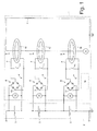
Figure 1 shows a schematic of a management unit, for managing electric energy stored in a battery comprising a number of series-connected cells, in accordance with the present invention; -
Figures 2 and3 show schematics of two alternative embodiments of theFigure 1 electric energy management unit. -
Number 1 inFigure 1 indicates as a whole a management (or equalizing) unit for managing electric energy stored in abattery 2 comprising a number of series-connected cells 3 (only a few of which are shown inFigure 1 ). -
Management unit 1 comprises a main equalizingcircuit 4, which forms the primary of anelectric transformer 5 and has a constant alternating-current generator 6 powered bybattery 2 and which feeds alternating current of constant intensity through main equalizingcircuit 4. - For each
cell 3 ofbattery 2,management unit 1 comprises a secondary equalizingcircuit 7, which forms the secondary ofelectric transformer 5 and is therefore coupled magnetically to main equalizingcircuit 4. Each secondary equalizingcircuit 7 is connected parallel tocell 3, i.e. the two terminals of secondary equalizingcircuit 7 are connected to the two terminals ofcorresponding cell 3, and has a one-wayelectronic device 8 which imposes electric current flow tocell 3 in one direction only. More specifically, each one-wayelectronic device 8 imposes one-way electric current flow into a positive terminal ofcell 3 and out from a negative terminal of cell 3 (i.e. the electric current throughcell 3 and generated in secondary equalizingcircuit 7 simply charges cell 3). Finally, each secondary equalizingcircuit 7 is connected to adrive device 9, which can be activated to zero the voltage applied tocell 3 by secondary equalizingcircuit 7, i.e. to prevent current generated in secondary equalizingcircuit 7 from circulating throughcell 3. - Each secondary equalizing
circuit 7 comprises amagnetic ring 10 of ferromagnetic material, which forms the magnetic core oftransformer 5 and is coupled magnetically to both secondary equalizingcircuit 7 and main equalizingcircuit 4. Each secondary equalizingcircuit 7 comprises a single turn coupled magnetically to correspondingmagnetic ring 10; and main equalizingcircuit 4 comprises a single turn coupled magnetically to all themagnetic rings 10. In other words, as shown clearly inFigure 1 , main equalizingcircuit 4 extends through the centre of all themagnetic rings 10, with no further turns aboutmagnetic rings 10; and each secondary equalizingcircuit 7 extends through the centre of correspondingmagnetic ring 10, with no further turns aboutmagnetic ring 10. In an alternative embodiment not shown, main equalizingcircuit 4 and/or secondary equalizingcircuits 7 each comprise a number of turns aboutmagnetic rings 10. - Each
transformer 5 obviously has a transformation ratio of 1.0, i.e. the alternating current through main equalizingcircuit 4 has the same intensity as the alternating current through each secondary equalizingcircuit 7. In typical automotive applications, alternating-current generator 6 generates electric current of a few (e.g. 5) amperes, and a frequency of 100 to 300 kHz. - In the
Figure 1 embodiment, eachdrive device 9 comprises acontrol switch 11, which is activated to short-circuit the corresponding secondary equalizingcircuit 7 upstream from one-wayelectronic device 8. Eachcontrol switch 11 may be electromechanical (e.g. a relay) or fully electronic (e.g. a single MOSFET transistor or a more complex electronic circuit comprising at least one MOSFET transistor). Whencontrol switch 11 is deactivated (open), the corresponding secondary equalizingcircuit 7 is not short-circuited, and so feeds electric current throughcell 3 to recharge - (i.e. supply energy to) it. That is, the alternating electric current induced in secondary equalizing
circuit 7 by main equalizingcircuit 4 coupled magnetically bytransformer 5 must flow through cell 3 (obviously, only when flowing in the direction permitted by one-way electronic device 8) which is thus recharged. Conversely, whencontrol switch 11 is activated (closed), the corresponding secondary equalizingcircuit 7 is short-circuited and so feeds no electric current throughcell 3. That is, the alternating electric current induced in secondary equalizingcircuit 7 by main equalizingcircuit 4 coupled magnetically bytransformer 5 flows throughcontrol switch 11 and has no effect oncell 3. - It is important to note that, when activated (closed),
control switch 11 has a voltage drop of a few tens of millivolts (e.g. 0.05 volts) at its terminals. So, assumingcurrent generator 6 generates an electric current of 5 amperes, the power loss in an activated (closed)control switch 11 is only a few tens of milliwatts (e.g. 0.025 watts with a voltage drop of 0.05 volts and 5 ampere current). Not being a source of significant energy losses,control switches 11 therefore need not be designed to dispose of much heat, and have no significant negative effect on the efficiency ofmanagement unit 1. - In the alternative embodiment shown in
Figures 2 and3 , eachdrive device 9 comprises acontrol circuit 12 coupled magnetically tomagnetic ring 10 of corresponding secondary equalizingcircuit 7, and havingcontrol switch 11, which is activated to short-circuit control circuit 12. TheFigure 2 and3 embodiment ofdrive device 9 operates in the same way as theFigure 1 embodiment, the only difference being that, in theFigure 1 embodiment ofdrive device 9,control switch 11 short-circuits secondary equalizingcircuit 7 directly (by being connected directly to secondary equalizing circuit 7), whereas, in theFigure 2 and3 embodiment ofdrive device 9,control switch 11 short-circuits secondary equalizingcircuit 7 indirectly (by being connected tocontrol circuit 12 coupled magnetically tomagnetic ring 10 of secondary equalizing circuit 7). - In other words, when
control switch 11 is deactivated (open), the corresponding secondary equalizingcircuit 7 is not short-circuited, and so feeds electric current throughcell 3 to recharge (i.e. supply energy to) it. That is, the alternating electric current induced by main equalizingcircuit 4 coupled magnetically bytransformer 5 can only flow through corresponding secondary equalizingcircuit 7 and hence throughcell 3 to recharge (i.e. supply energy to)cell 3. Conversely, whencontrol switch 11 is activated (closed), the corresponding secondary equalizingcircuit 7 is short-circuited and so feeds no electric current throughcell 3. That is, the alternating electric current induced in secondary equalizingcircuit 7 by main equalizingcircuit 4 coupled magnetically bytransformer 5 flows throughcontrol circuit 12 and has no effect oncell 3. - In the
Figure 1 and2 embodiments, each one-wayelectronic device 8 is defined by a rectifying bridge 13 (e.g. a Wheatstone bridge comprising four four-arm-connected diodes). In theFigure 3 embodiment, each one-wayelectronic device 8 is defined by onediode 14. Compared with theFigure 1 and2 embodiment, theFigure 3 embodiment of one-wayelectronic device 8 has the disadvantage of only being able to supplycell 3 with half the alternating current induced in secondary equalizing circuit 7 (i.e. only the 'positive' half-wave and not the 'negative' half-wave), but has the advantage of being simpler in design (only one diode as opposed to four) and of involving only half the power loss (current only has to flow through one diode as opposed to two series-connected diodes). - For each
cell 3 ofbattery 2,management unit 1 comprises at least onesensor 15 connected tocell 3 to determine its charge status. In the preferred embodiment shown in the drawings, eachsensor 15 is a voltmeter, is connected parallel torespective cell 3, and measures the voltage at the terminals ofcell 3. Using an equation obtainable experimentally and the voltage at the terminals ofcell 3, it is possible to accurately determine the charge ofcell 3. In a variation, a temperature sensor also determines the temperature ofcell 3, which is used together with the voltage measurement at the terminals ofcell 3 to determine the charge ofcell 3. -
Management unit 1 also comprises acontrol device 16, which controls alternating-current generator 6 anddrive devices 9 to equalize the capacities ofcells 3 ofbattery 2 by transferring energy from the better-performing to lesser-performingcells 3 as the battery discharges, and transferring energy to the better-performingcells 3 as the battery charges. - To transfer energy to a given
cell 3, alternating electric current must flow through main equalizingcircuit 4, and thecorresponding drive device 9 must be deactivated (as stated, whendrive device 9 is activated, no energy can be transferred to corresponding cell 3). - In actual use,
control device 16 determines the charge status of eachcell 3 by means ofrespective sensor 15 connected tocell 3. The charge status ofcell 3 is typically expressed as the amount of charge stored incell 3, which may be either absolute (i.e. measured, for example, in ampere-hours) or relative (e.g. expressed as a percentage of maximum or rated charge). By comparing the charge status ofcells 3,control device 16 determines whichcells 3 have a non-deficit-charge status (i.e. not much below average), and which have a deficit-charge status (i.e. well below average). For example, given an average charge status (calculated as the arithmetic, possibly weighted, mean of the charge status of all of cells 3), anycells 3 with a charge status not below 90 percent of average are considered non-deficit-charge status cells, and anycells 3 with a charge status below 90 percent of average are considered deficit-charge status cells. - In actual use,
control device 16 activatesrespective drive device 9 to prevent energy transfer from main equalizingcircuit 4 to eachsecondary equalizing circuit 7 connected to a non-deficit-charge status cell 3, and deactivatesrespective drive device 9 to transfer energy from main equalizingcircuit 4 to eachsecondary equalizing circuit 7 connected to a deficit-charge status cell 3. By so doing, energy is transferred from the better-performing cells 3 (with a non-deficit-charge status) to the lesser-performing cells 3 (with a deficit-charge status). In this connection, it is important to note that, alternating-current generator 6 being powered by battery 2 (i.e. by all the series-connected cells 3), the electric energy supplied by main equalizingcircuit 4 comes fromcells 3. - It is important to note that the electric power transferable to
cell 3 by respectivesecondary equalizing circuit 7 is directly proportional to the intensity of the alternating current inmain equalizing circuit 4. So, by adjusting the intensity of the alternating current in main equalizing circuit 4 (i.e. adjusting alternating-current generator 6), it is possible to adjust the effectiveness ofsecondary equalizing circuits 7. Increasing the intensity of the alternating current inmain equalizing circuit 4 increases the electric power transferable tocell 3 by respectivesecondary equalizing circuit 7, but also increases power losses inmanagement unit 1. In one embodiment, the intensity of the alternating current inmain equalizing circuit 4 can be adjusted as a function of the overall condition ofbattery 2, so that, in any situation, the intensity of the alternating current inmain equalizing circuit 4 represents an ideal compromise between the need to transfer energy rapidly to the lesser-performingcells 3, and the need to maintain low power losses. For example, whencells 3 are all highly charged, so no energy need be transferred between them, the intensity of the alternating current inmain equalizing circuit 4 may be zero or at any rate very low; whereas, whencells 3 are poorly charged, so large amounts of energy need be transferred between them, the intensity of the alternating current inmain equalizing circuit 4 must be high. The intensity of the alternating current inmain equalizing circuit 4 may therefore be inversely proportional to the mean charge status of cells 3 (the higher the mean charge status ofcells 3, the lower the intensity of the alternating current in main equalizing circuit 4). - Besides being highly effective and efficient, the electric
energy management unit 1 described is also extremely simple, strong and compact. This is due to the extremely simple, compact design of the magnetic circuits oftransformers 5 defined bymagnetic rings 10, and the fact that equalizingcircuits
Claims (11)
- A management unit (1) for managing electric energy stored in a battery (2) comprising a number of series-connected cells (3), the management unit (1) comprising:a main equalizing circuit (4), which forms the primary of an electric transformer (5) and has an electric alternating-current generator (6); andfor each cell (3) of the battery (2), a secondary equalizing circuit (7), which forms the secondary of the electric transformer (5) and is therefore coupled magnetically to the main equalizing circuit (4), is connected parallel to the cell (3), has a one-way electronic device (8) which imposes electric current flow to the cell (3) in one direction only, and is connected to a drive device (9) that can be activated to zero the voltage applied to the cell (3) by the secondary equalizing circuit (7);the management unit (1) being characterized in that the electric alternating-current generator (6) is a constant alternating-current generator, which is powered by the battery (2) and feeds alternating current of constant intensity through the main equalizing circuit (4).
- A management unit (1) as claimed in Claim 1, and comprising:for each cell (3) of the battery (2), at least one sensor (15) connected to the cell (3) to determine the charge status of the cell (3); anda control device (16), which activates the corresponding drive device (9) to prevent energy transfer from the main equalizing circuit (4) to each secondary equalizing circuit (7) connected to a non-deficit-charge status cell (3), and deactivates the corresponding drive device (9) to transfer energy from the main equalizing circuit (4) to each secondary equalizing circuit (7) connected to a deficit-charge status cell 3.
- A management unit (1) as claimed in Claim 1 or 2, wherein each secondary equalizing circuit (7) comprises a magnetic ring (10), which forms the magnetic core of the electric transformer (5) and is coupled magnetically to both the secondary equalizing circuit (7) and main equalizing circuit (4).
- A management unit (1) as claimed in Claim 3, wherein:each secondary equalizing circuit (7) comprises a single turn coupled magnetically to the corresponding magnetic ring (10); andthe main equalizing circuit (4) comprises a single turn coupled magnetically to all the magnetic rings (10).
- A management unit (1) as claimed in one of Claims 1 to 4, wherein each drive device (9) comprises a control switch (11), which is activated to short-circuit the corresponding secondary equalizing circuit (7) upstream from the one-way electronic device (8).
- A management unit (1) as claimed in one of Claims 1 to 4, wherein:each secondary equalizing circuit (7) comprises a magnetic ring (10), which forms the magnetic core of the electric transformer (5) and is coupled magnetically to both the secondary equalizing circuit (7) and main equalizing circuit (4);each drive device (9) comprises a control circuit (12) coupled magnetically to the magnetic ring (10) of the corresponding secondary equalizing circuit (7), and having a control switch (11), which is activated to short-circuit the control circuit (12).
- A management unit (1) as claimed in one of Claims 1 to 6, wherein each one-way electronic device (8) is defined by a diode (14).
- A management unit (1) as claimed in one of Claims 1 to 6, wherein each one-way electronic device (8) is defined by a rectifying bridge (13).
- A management unit (1) as claimed in one of Claims 1 to 8, wherein each one-way electronic device (8) imposes electric current flow to the cell (3) in one direction only, which is into a positive terminal of the cell (3) and out of a negative terminal of the cell (3).
- A management unit (1) as claimed in one of Claims 1 to 9, wherein the control device (16) adjusts the intensity of the alternating current in the main equalizing circuit (4) by adjusting the electric alternating-current generator (6) as a function of the overall condition of the battery (2).
- A method of managing electric energy stored in a battery (2) comprising a number of series-connected cells (3); the method comprising the steps of:constructing a main equalizing circuit (4), which forms the primary of an electric transformer (5), has a constant alternating-current generator (6) powered by the battery (2), and which feeds alternating current of constant intensity through the main equalizing circuit (4);constructing, for each cell (3) of the battery (2), a secondary equalizing circuit (7), which forms the secondary of the electric transformer (5) and is therefore coupled magnetically to the main equalizing circuit (4), is connected parallel to the cell (3), has a one-way electronic device (8) which imposes electric current flow to the cell (3) in one direction only, and is connected to a drive device (9) that can be activated to zero the voltage applied to the cell (3) by the secondary equalizing circuit (7);determining the charge status of each cell (3) by means of at least one respective sensor (15) connected to the cell (3);activating the corresponding drive device (9) to prevent energy transfer from the main equalizing circuit (4) to each secondary equalizing circuit (7) connected to a cell (3) with a non-deficit-charge status; anddeactivating the corresponding drive device (9) to transfer energy from the main equalizing circuit (4) to each secondary equalizing circuit (7) connected to a cell (3) with a deficit-charge status.
Applications Claiming Priority (1)
| Application Number | Priority Date | Filing Date | Title |
|---|---|---|---|
| ITBO2010A000102A IT1398483B1 (en) | 2010-02-24 | 2010-02-24 | UNIT AND METHOD OF MANAGEMENT OF ELECTRICITY STORED IN A BATTERY CONSISTING OF A PLURALITY OF CELLS CONNECTED IN SERIES. |
Publications (2)
| Publication Number | Publication Date |
|---|---|
| EP2360811A1 true EP2360811A1 (en) | 2011-08-24 |
| EP2360811B1 EP2360811B1 (en) | 2016-04-20 |
Family
ID=42985510
Family Applications (1)
| Application Number | Title | Priority Date | Filing Date |
|---|---|---|---|
| EP11155874.8A Not-in-force EP2360811B1 (en) | 2010-02-24 | 2011-02-24 | Management unit and method for managing electric energy stored in a battery comprising a number of series-connected cells |
Country Status (5)
| Country | Link |
|---|---|
| US (1) | US8410754B2 (en) |
| EP (1) | EP2360811B1 (en) |
| CN (1) | CN102222805B (en) |
| BR (1) | BRPI1100333B1 (en) |
| IT (1) | IT1398483B1 (en) |
Cited By (1)
| Publication number | Priority date | Publication date | Assignee | Title |
|---|---|---|---|---|
| CN121055542A (en) * | 2025-10-31 | 2025-12-02 | 中车株洲电力机车研究所有限公司 | A multi-feature active balancing method and system based on battery energy storage system |
Families Citing this family (5)
| Publication number | Priority date | Publication date | Assignee | Title |
|---|---|---|---|---|
| US9136713B1 (en) * | 2012-01-13 | 2015-09-15 | Win Cheng | Proactive and highly efficient active balance apparatus for a battery power system |
| CN103855747B (en) * | 2012-12-05 | 2017-02-08 | 凹凸电子(武汉)有限公司 | battery system and battery charging method |
| US8901888B1 (en) | 2013-07-16 | 2014-12-02 | Christopher V. Beckman | Batteries for optimizing output and charge balance with adjustable, exportable and addressable characteristics |
| US9368979B2 (en) | 2013-03-15 | 2016-06-14 | O2Micro Inc | System and methods for battery balancing |
| DE102013112923A1 (en) * | 2013-11-22 | 2015-05-28 | H-Tech Ag | Battery management system for controlling an energy storage device and method for charging and discharging an energy storage device |
Citations (3)
| Publication number | Priority date | Publication date | Assignee | Title |
|---|---|---|---|---|
| FR2408241A1 (en) * | 1977-11-08 | 1979-06-01 | Guerbet Francois | AC=DC converter for battery charging circuit - has circuit injecting dC current in same direction as secondary current from rectifier |
| WO2003092148A1 (en) * | 2002-04-25 | 2003-11-06 | Abb Patent Gmbh | Switched-mode power supply arrangement |
| WO2007145463A1 (en) | 2006-06-15 | 2007-12-21 | Sk Energy Co., Ltd. | Charge equalization apparatus |
Family Cites Families (1)
| Publication number | Priority date | Publication date | Assignee | Title |
|---|---|---|---|---|
| KR101188944B1 (en) * | 2006-06-15 | 2012-10-08 | 한국과학기술원 | Charge equalization apparatus with parallel connection of secondary windings of multiple transformers |
-
2010
- 2010-02-24 IT ITBO2010A000102A patent/IT1398483B1/en active
-
2011
- 2011-02-23 US US13/033,172 patent/US8410754B2/en not_active Expired - Fee Related
- 2011-02-24 EP EP11155874.8A patent/EP2360811B1/en not_active Not-in-force
- 2011-02-24 BR BRPI1100333-2A patent/BRPI1100333B1/en not_active IP Right Cessation
- 2011-02-24 CN CN201110044526.6A patent/CN102222805B/en not_active Expired - Fee Related
Patent Citations (3)
| Publication number | Priority date | Publication date | Assignee | Title |
|---|---|---|---|---|
| FR2408241A1 (en) * | 1977-11-08 | 1979-06-01 | Guerbet Francois | AC=DC converter for battery charging circuit - has circuit injecting dC current in same direction as secondary current from rectifier |
| WO2003092148A1 (en) * | 2002-04-25 | 2003-11-06 | Abb Patent Gmbh | Switched-mode power supply arrangement |
| WO2007145463A1 (en) | 2006-06-15 | 2007-12-21 | Sk Energy Co., Ltd. | Charge equalization apparatus |
Cited By (1)
| Publication number | Priority date | Publication date | Assignee | Title |
|---|---|---|---|---|
| CN121055542A (en) * | 2025-10-31 | 2025-12-02 | 中车株洲电力机车研究所有限公司 | A multi-feature active balancing method and system based on battery energy storage system |
Also Published As
| Publication number | Publication date |
|---|---|
| CN102222805A (en) | 2011-10-19 |
| BRPI1100333A2 (en) | 2014-03-04 |
| EP2360811B1 (en) | 2016-04-20 |
| US8410754B2 (en) | 2013-04-02 |
| IT1398483B1 (en) | 2013-03-01 |
| CN102222805B (en) | 2015-04-08 |
| ITBO20100102A1 (en) | 2011-08-25 |
| BRPI1100333B1 (en) | 2020-03-24 |
| US20110309797A1 (en) | 2011-12-22 |
Similar Documents
| Publication | Publication Date | Title |
|---|---|---|
| CN101467328B (en) | Charge equalization equipment | |
| KR101893045B1 (en) | Charge balancing system for batteries | |
| CN101606300B (en) | Balance charging equipment | |
| KR101124800B1 (en) | Charge Equalization Apparatus | |
| US9160185B2 (en) | Apparatus and method for active balancing of series cells and series packs in a battery system | |
| CN101409455B (en) | Voltage balance apparatus and method for battery system | |
| US20130076310A1 (en) | Balancing system for power battery and corresponding load balancing method | |
| EP2360811B1 (en) | Management unit and method for managing electric energy stored in a battery comprising a number of series-connected cells | |
| US8269455B2 (en) | Charge balancing system | |
| CN102368628B (en) | Intelligent balance device of power batteries of electric vehicle | |
| CN102823104B (en) | Charge equalization system for batteries | |
| EP2036185A1 (en) | Charge equalization apparatus with parallel connection of primary windings of multiple transformers | |
| CN107251354A (en) | Electric Vehicle Power Distribution System | |
| JP6480935B2 (en) | Charge balance device | |
| TW201336200A (en) | Series battery balance charging/discharging circuit and control method thereof | |
| TWI484723B (en) | Battery bidirectional balancing circuit | |
| Jwo et al. | Design and implementation of a charge equalization using positive/negative pulse charger | |
| KR20140124485A (en) | CONTROL POWER CIRCUIT of ENERGY STORAGE SYSTEM | |
| Suryoatmojo et al. | Implementation of Charging Equalizer with Master-Slave Method on Lithium-Ion Batteries | |
| TWM437568U (en) | Rechargeable battery management device | |
| RU2510658C1 (en) | Hierarchical three-level control system for high-voltage battery of electric energy accumulators | |
| CN106252757A (en) | Battery pack balancing device | |
| CN120454266A (en) | Charging circuit and vehicle | |
| CN118971244A (en) | A battery management system for independently controlling the voltage boost of battery cells | |
| Tsapras et al. | A new equalization scheme for series connected battery cells |
Legal Events
| Date | Code | Title | Description |
|---|---|---|---|
| PUAI | Public reference made under article 153(3) epc to a published international application that has entered the european phase |
Free format text: ORIGINAL CODE: 0009012 |
|
| AK | Designated contracting states |
Kind code of ref document: A1 Designated state(s): AL AT BE BG CH CY CZ DE DK EE ES FI FR GB GR HR HU IE IS IT LI LT LU LV MC MK MT NL NO PL PT RO RS SE SI SK SM TR |
|
| AX | Request for extension of the european patent |
Extension state: BA ME |
|
| 17P | Request for examination filed |
Effective date: 20120224 |
|
| GRAP | Despatch of communication of intention to grant a patent |
Free format text: ORIGINAL CODE: EPIDOSNIGR1 |
|
| INTG | Intention to grant announced |
Effective date: 20151020 |
|
| GRAS | Grant fee paid |
Free format text: ORIGINAL CODE: EPIDOSNIGR3 |
|
| GRAA | (expected) grant |
Free format text: ORIGINAL CODE: 0009210 |
|
| AK | Designated contracting states |
Kind code of ref document: B1 Designated state(s): AL AT BE BG CH CY CZ DE DK EE ES FI FR GB GR HR HU IE IS IT LI LT LU LV MC MK MT NL NO PL PT RO RS SE SI SK SM TR |
|
| REG | Reference to a national code |
Ref country code: GB Ref legal event code: FG4D |
|
| REG | Reference to a national code |
Ref country code: CH Ref legal event code: EP |
|
| REG | Reference to a national code |
Ref country code: AT Ref legal event code: REF Ref document number: 793386 Country of ref document: AT Kind code of ref document: T Effective date: 20160515 |
|
| REG | Reference to a national code |
Ref country code: IE Ref legal event code: FG4D |
|
| REG | Reference to a national code |
Ref country code: DE Ref legal event code: R096 Ref document number: 602011025442 Country of ref document: DE |
|
| REG | Reference to a national code |
Ref country code: LT Ref legal event code: MG4D |
|
| REG | Reference to a national code |
Ref country code: AT Ref legal event code: MK05 Ref document number: 793386 Country of ref document: AT Kind code of ref document: T Effective date: 20160420 |
|
| REG | Reference to a national code |
Ref country code: NL Ref legal event code: MP Effective date: 20160420 |
|
| PG25 | Lapsed in a contracting state [announced via postgrant information from national office to epo] |
Ref country code: NL Free format text: LAPSE BECAUSE OF FAILURE TO SUBMIT A TRANSLATION OF THE DESCRIPTION OR TO PAY THE FEE WITHIN THE PRESCRIBED TIME-LIMIT Effective date: 20160420 Ref country code: LT Free format text: LAPSE BECAUSE OF FAILURE TO SUBMIT A TRANSLATION OF THE DESCRIPTION OR TO PAY THE FEE WITHIN THE PRESCRIBED TIME-LIMIT Effective date: 20160420 Ref country code: FI Free format text: LAPSE BECAUSE OF FAILURE TO SUBMIT A TRANSLATION OF THE DESCRIPTION OR TO PAY THE FEE WITHIN THE PRESCRIBED TIME-LIMIT Effective date: 20160420 Ref country code: NO Free format text: LAPSE BECAUSE OF FAILURE TO SUBMIT A TRANSLATION OF THE DESCRIPTION OR TO PAY THE FEE WITHIN THE PRESCRIBED TIME-LIMIT Effective date: 20160720 Ref country code: PL Free format text: LAPSE BECAUSE OF FAILURE TO SUBMIT A TRANSLATION OF THE DESCRIPTION OR TO PAY THE FEE WITHIN THE PRESCRIBED TIME-LIMIT Effective date: 20160420 |
|
| PG25 | Lapsed in a contracting state [announced via postgrant information from national office to epo] |
Ref country code: AT Free format text: LAPSE BECAUSE OF FAILURE TO SUBMIT A TRANSLATION OF THE DESCRIPTION OR TO PAY THE FEE WITHIN THE PRESCRIBED TIME-LIMIT Effective date: 20160420 Ref country code: HR Free format text: LAPSE BECAUSE OF FAILURE TO SUBMIT A TRANSLATION OF THE DESCRIPTION OR TO PAY THE FEE WITHIN THE PRESCRIBED TIME-LIMIT Effective date: 20160420 Ref country code: RS Free format text: LAPSE BECAUSE OF FAILURE TO SUBMIT A TRANSLATION OF THE DESCRIPTION OR TO PAY THE FEE WITHIN THE PRESCRIBED TIME-LIMIT Effective date: 20160420 Ref country code: SE Free format text: LAPSE BECAUSE OF FAILURE TO SUBMIT A TRANSLATION OF THE DESCRIPTION OR TO PAY THE FEE WITHIN THE PRESCRIBED TIME-LIMIT Effective date: 20160420 Ref country code: GR Free format text: LAPSE BECAUSE OF FAILURE TO SUBMIT A TRANSLATION OF THE DESCRIPTION OR TO PAY THE FEE WITHIN THE PRESCRIBED TIME-LIMIT Effective date: 20160721 Ref country code: PT Free format text: LAPSE BECAUSE OF FAILURE TO SUBMIT A TRANSLATION OF THE DESCRIPTION OR TO PAY THE FEE WITHIN THE PRESCRIBED TIME-LIMIT Effective date: 20160822 Ref country code: ES Free format text: LAPSE BECAUSE OF FAILURE TO SUBMIT A TRANSLATION OF THE DESCRIPTION OR TO PAY THE FEE WITHIN THE PRESCRIBED TIME-LIMIT Effective date: 20160420 Ref country code: LV Free format text: LAPSE BECAUSE OF FAILURE TO SUBMIT A TRANSLATION OF THE DESCRIPTION OR TO PAY THE FEE WITHIN THE PRESCRIBED TIME-LIMIT Effective date: 20160420 |
|
| PG25 | Lapsed in a contracting state [announced via postgrant information from national office to epo] |
Ref country code: BE Free format text: LAPSE BECAUSE OF FAILURE TO SUBMIT A TRANSLATION OF THE DESCRIPTION OR TO PAY THE FEE WITHIN THE PRESCRIBED TIME-LIMIT Effective date: 20160420 |
|
| REG | Reference to a national code |
Ref country code: DE Ref legal event code: R097 Ref document number: 602011025442 Country of ref document: DE |
|
| REG | Reference to a national code |
Ref country code: FR Ref legal event code: PLFP Year of fee payment: 7 |
|
| PG25 | Lapsed in a contracting state [announced via postgrant information from national office to epo] |
Ref country code: SK Free format text: LAPSE BECAUSE OF FAILURE TO SUBMIT A TRANSLATION OF THE DESCRIPTION OR TO PAY THE FEE WITHIN THE PRESCRIBED TIME-LIMIT Effective date: 20160420 Ref country code: CZ Free format text: LAPSE BECAUSE OF FAILURE TO SUBMIT A TRANSLATION OF THE DESCRIPTION OR TO PAY THE FEE WITHIN THE PRESCRIBED TIME-LIMIT Effective date: 20160420 Ref country code: RO Free format text: LAPSE BECAUSE OF FAILURE TO SUBMIT A TRANSLATION OF THE DESCRIPTION OR TO PAY THE FEE WITHIN THE PRESCRIBED TIME-LIMIT Effective date: 20160420 Ref country code: DK Free format text: LAPSE BECAUSE OF FAILURE TO SUBMIT A TRANSLATION OF THE DESCRIPTION OR TO PAY THE FEE WITHIN THE PRESCRIBED TIME-LIMIT Effective date: 20160420 Ref country code: EE Free format text: LAPSE BECAUSE OF FAILURE TO SUBMIT A TRANSLATION OF THE DESCRIPTION OR TO PAY THE FEE WITHIN THE PRESCRIBED TIME-LIMIT Effective date: 20160420 |
|
| PLBE | No opposition filed within time limit |
Free format text: ORIGINAL CODE: 0009261 |
|
| STAA | Information on the status of an ep patent application or granted ep patent |
Free format text: STATUS: NO OPPOSITION FILED WITHIN TIME LIMIT |
|
| PG25 | Lapsed in a contracting state [announced via postgrant information from national office to epo] |
Ref country code: SM Free format text: LAPSE BECAUSE OF FAILURE TO SUBMIT A TRANSLATION OF THE DESCRIPTION OR TO PAY THE FEE WITHIN THE PRESCRIBED TIME-LIMIT Effective date: 20160420 |
|
| 26N | No opposition filed |
Effective date: 20170123 |
|
| PG25 | Lapsed in a contracting state [announced via postgrant information from national office to epo] |
Ref country code: SI Free format text: LAPSE BECAUSE OF FAILURE TO SUBMIT A TRANSLATION OF THE DESCRIPTION OR TO PAY THE FEE WITHIN THE PRESCRIBED TIME-LIMIT Effective date: 20160420 |
|
| PG25 | Lapsed in a contracting state [announced via postgrant information from national office to epo] |
Ref country code: MC Free format text: LAPSE BECAUSE OF FAILURE TO SUBMIT A TRANSLATION OF THE DESCRIPTION OR TO PAY THE FEE WITHIN THE PRESCRIBED TIME-LIMIT Effective date: 20160420 |
|
| REG | Reference to a national code |
Ref country code: CH Ref legal event code: PL |
|
| GBPC | Gb: european patent ceased through non-payment of renewal fee |
Effective date: 20170224 |
|
| PG25 | Lapsed in a contracting state [announced via postgrant information from national office to epo] |
Ref country code: LI Free format text: LAPSE BECAUSE OF NON-PAYMENT OF DUE FEES Effective date: 20170228 Ref country code: CH Free format text: LAPSE BECAUSE OF NON-PAYMENT OF DUE FEES Effective date: 20170228 |
|
| REG | Reference to a national code |
Ref country code: IE Ref legal event code: MM4A |
|
| PG25 | Lapsed in a contracting state [announced via postgrant information from national office to epo] |
Ref country code: LU Free format text: LAPSE BECAUSE OF NON-PAYMENT OF DUE FEES Effective date: 20170224 |
|
| REG | Reference to a national code |
Ref country code: FR Ref legal event code: PLFP Year of fee payment: 8 |
|
| PG25 | Lapsed in a contracting state [announced via postgrant information from national office to epo] |
Ref country code: GB Free format text: LAPSE BECAUSE OF NON-PAYMENT OF DUE FEES Effective date: 20170224 Ref country code: IE Free format text: LAPSE BECAUSE OF NON-PAYMENT OF DUE FEES Effective date: 20170224 |
|
| PGFP | Annual fee paid to national office [announced via postgrant information from national office to epo] |
Ref country code: TR Payment date: 20180201 Year of fee payment: 8 |
|
| PG25 | Lapsed in a contracting state [announced via postgrant information from national office to epo] |
Ref country code: MT Free format text: LAPSE BECAUSE OF NON-PAYMENT OF DUE FEES Effective date: 20170224 |
|
| PG25 | Lapsed in a contracting state [announced via postgrant information from national office to epo] |
Ref country code: AL Free format text: LAPSE BECAUSE OF FAILURE TO SUBMIT A TRANSLATION OF THE DESCRIPTION OR TO PAY THE FEE WITHIN THE PRESCRIBED TIME-LIMIT Effective date: 20160420 |
|
| PG25 | Lapsed in a contracting state [announced via postgrant information from national office to epo] |
Ref country code: HU Free format text: LAPSE BECAUSE OF FAILURE TO SUBMIT A TRANSLATION OF THE DESCRIPTION OR TO PAY THE FEE WITHIN THE PRESCRIBED TIME-LIMIT; INVALID AB INITIO Effective date: 20110224 |
|
| PG25 | Lapsed in a contracting state [announced via postgrant information from national office to epo] |
Ref country code: BG Free format text: LAPSE BECAUSE OF FAILURE TO SUBMIT A TRANSLATION OF THE DESCRIPTION OR TO PAY THE FEE WITHIN THE PRESCRIBED TIME-LIMIT Effective date: 20160420 |
|
| PG25 | Lapsed in a contracting state [announced via postgrant information from national office to epo] |
Ref country code: CY Free format text: LAPSE BECAUSE OF NON-PAYMENT OF DUE FEES Effective date: 20160420 |
|
| PG25 | Lapsed in a contracting state [announced via postgrant information from national office to epo] |
Ref country code: MK Free format text: LAPSE BECAUSE OF FAILURE TO SUBMIT A TRANSLATION OF THE DESCRIPTION OR TO PAY THE FEE WITHIN THE PRESCRIBED TIME-LIMIT Effective date: 20160420 |
|
| PG25 | Lapsed in a contracting state [announced via postgrant information from national office to epo] |
Ref country code: IS Free format text: LAPSE BECAUSE OF FAILURE TO SUBMIT A TRANSLATION OF THE DESCRIPTION OR TO PAY THE FEE WITHIN THE PRESCRIBED TIME-LIMIT Effective date: 20160820 |
|
| PGFP | Annual fee paid to national office [announced via postgrant information from national office to epo] |
Ref country code: DE Payment date: 20220119 Year of fee payment: 12 |
|
| PGFP | Annual fee paid to national office [announced via postgrant information from national office to epo] |
Ref country code: IT Payment date: 20220119 Year of fee payment: 12 Ref country code: FR Payment date: 20220119 Year of fee payment: 12 |
|
| PG25 | Lapsed in a contracting state [announced via postgrant information from national office to epo] |
Ref country code: TR Free format text: LAPSE BECAUSE OF NON-PAYMENT OF DUE FEES Effective date: 20190224 |
|
| REG | Reference to a national code |
Ref country code: DE Ref legal event code: R119 Ref document number: 602011025442 Country of ref document: DE |
|
| PG25 | Lapsed in a contracting state [announced via postgrant information from national office to epo] |
Ref country code: IT Free format text: LAPSE BECAUSE OF NON-PAYMENT OF DUE FEES Effective date: 20230224 Ref country code: FR Free format text: LAPSE BECAUSE OF NON-PAYMENT OF DUE FEES Effective date: 20230228 Ref country code: DE Free format text: LAPSE BECAUSE OF NON-PAYMENT OF DUE FEES Effective date: 20230901 |